EP4375103A1 - New energy bus - Google Patents
New energy bus Download PDFInfo
- Publication number
- EP4375103A1 EP4375103A1 EP22943401.4A EP22943401A EP4375103A1 EP 4375103 A1 EP4375103 A1 EP 4375103A1 EP 22943401 A EP22943401 A EP 22943401A EP 4375103 A1 EP4375103 A1 EP 4375103A1
- Authority
- EP
- European Patent Office
- Prior art keywords
- sealing
- bus
- heat exchange
- exchange plate
- liquid heat
- Prior art date
- Legal status (The legal status is an assumption and is not a legal conclusion. Google has not performed a legal analysis and makes no representation as to the accuracy of the status listed.)
- Granted
Links
Images

Classifications
-
- H—ELECTRICITY
- H01—ELECTRIC ELEMENTS
- H01M—PROCESSES OR MEANS, e.g. BATTERIES, FOR THE DIRECT CONVERSION OF CHEMICAL ENERGY INTO ELECTRICAL ENERGY
- H01M10/00—Secondary cells; Manufacture thereof
- H01M10/60—Heating or cooling; Temperature control
- H01M10/62—Heating or cooling; Temperature control specially adapted for specific applications
- H01M10/625—Vehicles
-
- B—PERFORMING OPERATIONS; TRANSPORTING
- B60—VEHICLES IN GENERAL
- B60H—ARRANGEMENTS OF HEATING, COOLING, VENTILATING OR OTHER AIR-TREATING DEVICES SPECIALLY ADAPTED FOR PASSENGER OR GOODS SPACES OF VEHICLES
- B60H1/00—Heating, cooling or ventilating devices
- B60H1/00271—HVAC devices specially adapted for particular vehicle parts or components and being connected to the vehicle HVAC unit
- B60H1/00278—HVAC devices specially adapted for particular vehicle parts or components and being connected to the vehicle HVAC unit for the battery
-
- B—PERFORMING OPERATIONS; TRANSPORTING
- B60—VEHICLES IN GENERAL
- B60H—ARRANGEMENTS OF HEATING, COOLING, VENTILATING OR OTHER AIR-TREATING DEVICES SPECIALLY ADAPTED FOR PASSENGER OR GOODS SPACES OF VEHICLES
- B60H1/00—Heating, cooling or ventilating devices
- B60H1/00357—Air-conditioning arrangements specially adapted for particular vehicles
- B60H1/00371—Air-conditioning arrangements specially adapted for particular vehicles for vehicles carrying large numbers of passengers, e.g. buses
-
- B—PERFORMING OPERATIONS; TRANSPORTING
- B60—VEHICLES IN GENERAL
- B60K—ARRANGEMENT OR MOUNTING OF PROPULSION UNITS OR OF TRANSMISSIONS IN VEHICLES; ARRANGEMENT OR MOUNTING OF PLURAL DIVERSE PRIME-MOVERS IN VEHICLES; AUXILIARY DRIVES FOR VEHICLES; INSTRUMENTATION OR DASHBOARDS FOR VEHICLES; ARRANGEMENTS IN CONNECTION WITH COOLING, AIR INTAKE, GAS EXHAUST OR FUEL SUPPLY OF PROPULSION UNITS IN VEHICLES
- B60K1/00—Arrangement or mounting of electrical propulsion units
-
- B—PERFORMING OPERATIONS; TRANSPORTING
- B60—VEHICLES IN GENERAL
- B60K—ARRANGEMENT OR MOUNTING OF PROPULSION UNITS OR OF TRANSMISSIONS IN VEHICLES; ARRANGEMENT OR MOUNTING OF PLURAL DIVERSE PRIME-MOVERS IN VEHICLES; AUXILIARY DRIVES FOR VEHICLES; INSTRUMENTATION OR DASHBOARDS FOR VEHICLES; ARRANGEMENTS IN CONNECTION WITH COOLING, AIR INTAKE, GAS EXHAUST OR FUEL SUPPLY OF PROPULSION UNITS IN VEHICLES
- B60K1/00—Arrangement or mounting of electrical propulsion units
- B60K1/04—Arrangement or mounting of electrical propulsion units of the electric storage means for propulsion
-
- B—PERFORMING OPERATIONS; TRANSPORTING
- B60—VEHICLES IN GENERAL
- B60L—PROPULSION OF ELECTRICALLY-PROPELLED VEHICLES; SUPPLYING ELECTRIC POWER FOR AUXILIARY EQUIPMENT OF ELECTRICALLY-PROPELLED VEHICLES; ELECTRODYNAMIC BRAKE SYSTEMS FOR VEHICLES IN GENERAL; MAGNETIC SUSPENSION OR LEVITATION FOR VEHICLES; MONITORING OPERATING VARIABLES OF ELECTRICALLY-PROPELLED VEHICLES; ELECTRIC SAFETY DEVICES FOR ELECTRICALLY-PROPELLED VEHICLES
- B60L50/00—Electric propulsion with power supplied within the vehicle
- B60L50/50—Electric propulsion with power supplied within the vehicle using propulsion power supplied by batteries or fuel cells
- B60L50/60—Electric propulsion with power supplied within the vehicle using propulsion power supplied by batteries or fuel cells using power supplied by batteries
- B60L50/64—Constructional details of batteries specially adapted for electric vehicles
-
- B—PERFORMING OPERATIONS; TRANSPORTING
- B60—VEHICLES IN GENERAL
- B60L—PROPULSION OF ELECTRICALLY-PROPELLED VEHICLES; SUPPLYING ELECTRIC POWER FOR AUXILIARY EQUIPMENT OF ELECTRICALLY-PROPELLED VEHICLES; ELECTRODYNAMIC BRAKE SYSTEMS FOR VEHICLES IN GENERAL; MAGNETIC SUSPENSION OR LEVITATION FOR VEHICLES; MONITORING OPERATING VARIABLES OF ELECTRICALLY-PROPELLED VEHICLES; ELECTRIC SAFETY DEVICES FOR ELECTRICALLY-PROPELLED VEHICLES
- B60L50/00—Electric propulsion with power supplied within the vehicle
- B60L50/50—Electric propulsion with power supplied within the vehicle using propulsion power supplied by batteries or fuel cells
- B60L50/60—Electric propulsion with power supplied within the vehicle using propulsion power supplied by batteries or fuel cells using power supplied by batteries
- B60L50/66—Arrangements of batteries
-
- B—PERFORMING OPERATIONS; TRANSPORTING
- B60—VEHICLES IN GENERAL
- B60L—PROPULSION OF ELECTRICALLY-PROPELLED VEHICLES; SUPPLYING ELECTRIC POWER FOR AUXILIARY EQUIPMENT OF ELECTRICALLY-PROPELLED VEHICLES; ELECTRODYNAMIC BRAKE SYSTEMS FOR VEHICLES IN GENERAL; MAGNETIC SUSPENSION OR LEVITATION FOR VEHICLES; MONITORING OPERATING VARIABLES OF ELECTRICALLY-PROPELLED VEHICLES; ELECTRIC SAFETY DEVICES FOR ELECTRICALLY-PROPELLED VEHICLES
- B60L58/00—Methods or circuit arrangements for monitoring or controlling batteries or fuel cells, specially adapted for electric vehicles
- B60L58/10—Methods or circuit arrangements for monitoring or controlling batteries or fuel cells, specially adapted for electric vehicles for monitoring or controlling batteries
- B60L58/24—Methods or circuit arrangements for monitoring or controlling batteries or fuel cells, specially adapted for electric vehicles for monitoring or controlling batteries for controlling the temperature of batteries
- B60L58/26—Methods or circuit arrangements for monitoring or controlling batteries or fuel cells, specially adapted for electric vehicles for monitoring or controlling batteries for controlling the temperature of batteries by cooling
-
- B—PERFORMING OPERATIONS; TRANSPORTING
- B60—VEHICLES IN GENERAL
- B60L—PROPULSION OF ELECTRICALLY-PROPELLED VEHICLES; SUPPLYING ELECTRIC POWER FOR AUXILIARY EQUIPMENT OF ELECTRICALLY-PROPELLED VEHICLES; ELECTRODYNAMIC BRAKE SYSTEMS FOR VEHICLES IN GENERAL; MAGNETIC SUSPENSION OR LEVITATION FOR VEHICLES; MONITORING OPERATING VARIABLES OF ELECTRICALLY-PROPELLED VEHICLES; ELECTRIC SAFETY DEVICES FOR ELECTRICALLY-PROPELLED VEHICLES
- B60L58/00—Methods or circuit arrangements for monitoring or controlling batteries or fuel cells, specially adapted for electric vehicles
- B60L58/10—Methods or circuit arrangements for monitoring or controlling batteries or fuel cells, specially adapted for electric vehicles for monitoring or controlling batteries
- B60L58/24—Methods or circuit arrangements for monitoring or controlling batteries or fuel cells, specially adapted for electric vehicles for monitoring or controlling batteries for controlling the temperature of batteries
- B60L58/27—Methods or circuit arrangements for monitoring or controlling batteries or fuel cells, specially adapted for electric vehicles for monitoring or controlling batteries for controlling the temperature of batteries by heating
-
- H—ELECTRICITY
- H01—ELECTRIC ELEMENTS
- H01M—PROCESSES OR MEANS, e.g. BATTERIES, FOR THE DIRECT CONVERSION OF CHEMICAL ENERGY INTO ELECTRICAL ENERGY
- H01M10/00—Secondary cells; Manufacture thereof
- H01M10/60—Heating or cooling; Temperature control
- H01M10/61—Types of temperature control
- H01M10/613—Cooling or keeping cold
-
- H—ELECTRICITY
- H01—ELECTRIC ELEMENTS
- H01M—PROCESSES OR MEANS, e.g. BATTERIES, FOR THE DIRECT CONVERSION OF CHEMICAL ENERGY INTO ELECTRICAL ENERGY
- H01M10/00—Secondary cells; Manufacture thereof
- H01M10/60—Heating or cooling; Temperature control
- H01M10/61—Types of temperature control
- H01M10/615—Heating or keeping warm
-
- H—ELECTRICITY
- H01—ELECTRIC ELEMENTS
- H01M—PROCESSES OR MEANS, e.g. BATTERIES, FOR THE DIRECT CONVERSION OF CHEMICAL ENERGY INTO ELECTRICAL ENERGY
- H01M10/00—Secondary cells; Manufacture thereof
- H01M10/60—Heating or cooling; Temperature control
- H01M10/65—Means for temperature control structurally associated with the cells
- H01M10/655—Solid structures for heat exchange or heat conduction
- H01M10/6554—Rods or plates
-
- H—ELECTRICITY
- H01—ELECTRIC ELEMENTS
- H01M—PROCESSES OR MEANS, e.g. BATTERIES, FOR THE DIRECT CONVERSION OF CHEMICAL ENERGY INTO ELECTRICAL ENERGY
- H01M10/00—Secondary cells; Manufacture thereof
- H01M10/60—Heating or cooling; Temperature control
- H01M10/65—Means for temperature control structurally associated with the cells
- H01M10/655—Solid structures for heat exchange or heat conduction
- H01M10/6556—Solid parts with flow channel passages or pipes for heat exchange
-
- H—ELECTRICITY
- H01—ELECTRIC ELEMENTS
- H01M—PROCESSES OR MEANS, e.g. BATTERIES, FOR THE DIRECT CONVERSION OF CHEMICAL ENERGY INTO ELECTRICAL ENERGY
- H01M10/00—Secondary cells; Manufacture thereof
- H01M10/60—Heating or cooling; Temperature control
- H01M10/65—Means for temperature control structurally associated with the cells
- H01M10/656—Means for temperature control structurally associated with the cells characterised by the type of heat-exchange fluid
- H01M10/6567—Liquids
-
- H—ELECTRICITY
- H01—ELECTRIC ELEMENTS
- H01M—PROCESSES OR MEANS, e.g. BATTERIES, FOR THE DIRECT CONVERSION OF CHEMICAL ENERGY INTO ELECTRICAL ENERGY
- H01M10/00—Secondary cells; Manufacture thereof
- H01M10/60—Heating or cooling; Temperature control
- H01M10/66—Heat-exchange relationships between the cells and other systems, e.g. central heating systems or fuel cells
- H01M10/663—Heat-exchange relationships between the cells and other systems, e.g. central heating systems or fuel cells the system being an air-conditioner or an engine
-
- H—ELECTRICITY
- H01—ELECTRIC ELEMENTS
- H01M—PROCESSES OR MEANS, e.g. BATTERIES, FOR THE DIRECT CONVERSION OF CHEMICAL ENERGY INTO ELECTRICAL ENERGY
- H01M50/00—Constructional details or processes of manufacture of the non-active parts of electrochemical cells other than fuel cells, e.g. hybrid cells
- H01M50/20—Mountings; Secondary casings or frames; Racks, modules or packs; Suspension devices; Shock absorbers; Transport or carrying devices; Holders
- H01M50/204—Racks, modules or packs for multiple batteries or multiple cells
-
- H—ELECTRICITY
- H01—ELECTRIC ELEMENTS
- H01M—PROCESSES OR MEANS, e.g. BATTERIES, FOR THE DIRECT CONVERSION OF CHEMICAL ENERGY INTO ELECTRICAL ENERGY
- H01M50/00—Constructional details or processes of manufacture of the non-active parts of electrochemical cells other than fuel cells, e.g. hybrid cells
- H01M50/20—Mountings; Secondary casings or frames; Racks, modules or packs; Suspension devices; Shock absorbers; Transport or carrying devices; Holders
- H01M50/249—Mountings; Secondary casings or frames; Racks, modules or packs; Suspension devices; Shock absorbers; Transport or carrying devices; Holders specially adapted for aircraft or vehicles, e.g. cars or trains
-
- H—ELECTRICITY
- H01—ELECTRIC ELEMENTS
- H01M—PROCESSES OR MEANS, e.g. BATTERIES, FOR THE DIRECT CONVERSION OF CHEMICAL ENERGY INTO ELECTRICAL ENERGY
- H01M50/00—Constructional details or processes of manufacture of the non-active parts of electrochemical cells other than fuel cells, e.g. hybrid cells
- H01M50/20—Mountings; Secondary casings or frames; Racks, modules or packs; Suspension devices; Shock absorbers; Transport or carrying devices; Holders
- H01M50/271—Lids or covers for the racks or secondary casings
-
- B—PERFORMING OPERATIONS; TRANSPORTING
- B60—VEHICLES IN GENERAL
- B60H—ARRANGEMENTS OF HEATING, COOLING, VENTILATING OR OTHER AIR-TREATING DEVICES SPECIALLY ADAPTED FOR PASSENGER OR GOODS SPACES OF VEHICLES
- B60H1/00—Heating, cooling or ventilating devices
- B60H1/00271—HVAC devices specially adapted for particular vehicle parts or components and being connected to the vehicle HVAC unit
- B60H2001/00307—Component temperature regulation using a liquid flow
-
- B—PERFORMING OPERATIONS; TRANSPORTING
- B60—VEHICLES IN GENERAL
- B60K—ARRANGEMENT OR MOUNTING OF PROPULSION UNITS OR OF TRANSMISSIONS IN VEHICLES; ARRANGEMENT OR MOUNTING OF PLURAL DIVERSE PRIME-MOVERS IN VEHICLES; AUXILIARY DRIVES FOR VEHICLES; INSTRUMENTATION OR DASHBOARDS FOR VEHICLES; ARRANGEMENTS IN CONNECTION WITH COOLING, AIR INTAKE, GAS EXHAUST OR FUEL SUPPLY OF PROPULSION UNITS IN VEHICLES
- B60K1/00—Arrangement or mounting of electrical propulsion units
- B60K1/04—Arrangement or mounting of electrical propulsion units of the electric storage means for propulsion
- B60K2001/0405—Arrangement or mounting of electrical propulsion units of the electric storage means for propulsion characterised by their position
- B60K2001/0438—Arrangement under the floor
-
- B—PERFORMING OPERATIONS; TRANSPORTING
- B60—VEHICLES IN GENERAL
- B60L—PROPULSION OF ELECTRICALLY-PROPELLED VEHICLES; SUPPLYING ELECTRIC POWER FOR AUXILIARY EQUIPMENT OF ELECTRICALLY-PROPELLED VEHICLES; ELECTRODYNAMIC BRAKE SYSTEMS FOR VEHICLES IN GENERAL; MAGNETIC SUSPENSION OR LEVITATION FOR VEHICLES; MONITORING OPERATING VARIABLES OF ELECTRICALLY-PROPELLED VEHICLES; ELECTRIC SAFETY DEVICES FOR ELECTRICALLY-PROPELLED VEHICLES
- B60L2200/00—Type of vehicles
- B60L2200/18—Buses
-
- B—PERFORMING OPERATIONS; TRANSPORTING
- B60—VEHICLES IN GENERAL
- B60L—PROPULSION OF ELECTRICALLY-PROPELLED VEHICLES; SUPPLYING ELECTRIC POWER FOR AUXILIARY EQUIPMENT OF ELECTRICALLY-PROPELLED VEHICLES; ELECTRODYNAMIC BRAKE SYSTEMS FOR VEHICLES IN GENERAL; MAGNETIC SUSPENSION OR LEVITATION FOR VEHICLES; MONITORING OPERATING VARIABLES OF ELECTRICALLY-PROPELLED VEHICLES; ELECTRIC SAFETY DEVICES FOR ELECTRICALLY-PROPELLED VEHICLES
- B60L2240/00—Control parameters of input or output; Target parameters
- B60L2240/10—Vehicle control parameters
- B60L2240/34—Cabin temperature
-
- H—ELECTRICITY
- H01—ELECTRIC ELEMENTS
- H01M—PROCESSES OR MEANS, e.g. BATTERIES, FOR THE DIRECT CONVERSION OF CHEMICAL ENERGY INTO ELECTRICAL ENERGY
- H01M2220/00—Batteries for particular applications
- H01M2220/20—Batteries in motive systems, e.g. vehicle, ship, plane
-
- Y—GENERAL TAGGING OF NEW TECHNOLOGICAL DEVELOPMENTS; GENERAL TAGGING OF CROSS-SECTIONAL TECHNOLOGIES SPANNING OVER SEVERAL SECTIONS OF THE IPC; TECHNICAL SUBJECTS COVERED BY FORMER USPC CROSS-REFERENCE ART COLLECTIONS [XRACs] AND DIGESTS
- Y02—TECHNOLOGIES OR APPLICATIONS FOR MITIGATION OR ADAPTATION AGAINST CLIMATE CHANGE
- Y02T—CLIMATE CHANGE MITIGATION TECHNOLOGIES RELATED TO TRANSPORTATION
- Y02T10/00—Road transport of goods or passengers
- Y02T10/60—Other road transportation technologies with climate change mitigation effect
- Y02T10/70—Energy storage systems for electromobility, e.g. batteries
Definitions
- the present invention relates to the field of new energy bus technologies, and specifically, to a battery arrangement in a new energy bus and heat exchange within a new energy bus.
- a plurality of battery cells form a battery pack through gluing, bolting, and the like.
- a plurality of battery packs are connected in a specific serial and parallel connection manner through high and low voltage wiring harnesses, a thermal management pipeline, and the like to form a battery system.
- the battery system is arranged and mounted on a chassis of the entire vehicle through a bracket, a bolt, and the like.
- the battery packs are mostly bottom-mounted or rear-mounted, which may easily cause damage to the battery packs due to collisions, wading, water immersion, and other factors, increase maintenance costs and affect bus operations.
- the prior art adopts a top-mounted battery pack solution. Specifically, a battery mounting frame is fixed on a bus top frame, a battery pack is fixed on the battery mounting frame, and then the battery pack is covered with a bus top cover.
- a battery mounting frame is fixed on a bus top frame
- a battery pack is fixed on the battery mounting frame
- the battery pack is covered with a bus top cover.
- the Chinese utility model patent with Publication No. CN206201949U adopts this manner.
- the battery pack usually includes a built-in liquid heat exchange plate. There is a flow channel in the liquid heat exchange plate. An air conditioning system is connected to the liquid heat exchange plate. Batteries in the battery pack are heated or cooled through the flow of a liquid, and the air conditioning system also heats or cools a passenger region. In current new energy buses, a passenger region top floor completely separates the battery pack from the passenger region.
- the liquid in the liquid heat exchange plate further exchanges heat with the air below and other objects on a top portion of the bus. This part of heat is directly dissipated to the air and cannot be effectively used, which results in low heat utilization of the entire vehicle, increases energy consumption, and shortens an endurance mileage.
- An objective of the present invention is to provide a new energy bus to solve the technical problems in the prior art of low space utilization and low heat utilization of the entire vehicle, resulting in a short endurance mileage.
- a new energy bus includes a bus body, and the bus body includes a bus top frame located on a top portion, a bus top skin covering a top portion of the bus top frame, and a passenger region top floor located below the bus top frame, where the bus top frame is fixedly provided with a liquid heat exchange plate, the liquid heat exchange plate is provided with a coolant inlet and a coolant outlet that are connected to an air conditioning system, a top surface of the liquid heat exchange plate is fixedly provided with a battery module, the bus top skin is directly or indirectly mounted with a sealing cover in a sealing manner covering an outer portion of the battery module, a filling body is disposed between the liquid heat exchange plate and the passenger region top floor and forms a sealed chamber with the liquid heat exchange plate and the passenger region top floor in a surrounding manner, a position on the passenger region top floor corresponding to the chamber is provided with a window in communication with a passenger region, the window is provided with a window
- the battery module is directly mounted on the bus top frame through the liquid heat exchange plate, and is provided with a sealing cover to form a sealed chamber to protect the battery module.
- a sealing cover to form a sealed chamber to protect the battery module.
- the blower blows the heat in the chamber to the passenger region in a form of cold or hot air to cool or heat the passenger region, which reduces power consumption required by the air conditioning system to cool or heat the passenger region, effectively utilizes the heat below the liquid heat exchange plate, improves the heat utilization of the entire vehicle, and increases the endurance mileage.
- the bus top skin is provided with an opening at the chamber, so that the liquid heat exchange plate is directly communicated with the chamber.
- the liquid heat exchange plate is directly communicated with the chamber, and the bottom portion of the liquid heat exchange plate directly exchanges heat with the chamber to heat or cool the chamber.
- the heat transfer efficiency is higher and the heat utilization is higher.
- a top portion of the filling body is in a sealing abutment on the liquid heat exchange plate, and a bottom portion of the filling body is in a sealing abutment on the passenger region top floor to form the chamber; or the liquid heat exchange plate is supported on the bus top skin and is in a sealing fit with the bus top skin, a top portion of the filling body is in a sealing abutment on the bus top skin, and a bottom portion of the filling body is in a sealing abutment on the passenger region top floor to form the chamber.
- the method is reasonably selected according to a size of the opening on the bus top skin to ensure the sealing of the chamber.
- blower is fixedly disposed on a bottom surface of the liquid heat exchange plate.
- the blower is fixedly disposed on the liquid heat exchange plate to avoid increasing a load on the passenger region top floor.
- the window body is rotatably mounted on the passenger region top floor
- the new energy bus includes a motor that drives the window body to rotate to open and close the window
- the new energy bus further includes a controller for controlling start and stop of the motor and a rotation direction
- the controller is configured to control the motor to open the window when both the battery module and the passenger region are cooled or heated, and control the motor to close the window when only one of the battery module and the passenger region is cooled or heated.
- the motor and the controller realize the automatic design of opening and closing the window body, without manual operation by personnel, and it is easy to use.
- an outer side of an edge of the liquid heat exchange plate is provided with a mounting ear, and the mounting ear is provided with a bolt through hole inside; and the bus top frame is provided with a threaded hole or pre-welded with a nut, the new energy bus includes a bolt running through the bolt through hole of the mounting ear and screwed into the threaded hole or the nut, and the bolt fixes the liquid heat exchange plate on the bus top frame.
- the liquid heat exchange plate is mounted on the bus top frame through threaded connection for easy disassembly and assembly.
- an edge position of the sealing cover is provided with a sealing flange, one of a bottom surface of the sealing flange and a top surface of the bus top skin is provided with a sealing gasket, the sealing flange is provided with a bolt through hole, the bus top skin is provided with a threaded hole or pre-welded with a nut, the new energy bus includes a bolt running through the bolt through hole of the sealing flange and screwed into the threaded hole or the nut on the bus top skin, the bolt fixes the sealing flange on the bus top skin, and the elastic deformation of sealing gasket is to ensure sealing performance between the sealing flange and the bus top skin.
- an edge position of the sealing cover is provided with a sealing flange, a position on the bus top skin corresponding to the sealing flange is welded with a sealing body, one of a bottom surface of the sealing flange and a top surface of the sealing body is provided with a sealing gasket, the sealing flange is provided with a bolt through hole, the sealing body is provided with a threaded hole or pre-welded with a nut, the new energy bus includes a bolt running through the bolt through hole of the sealing flange and screwed into the threaded hole or the nut on the sealing body, the bolt fixes the sealing flange on the sealing body, and the elastic deformation of sealing gasket is to ensure sealing performance between the sealing flange and the sealing body.
- an edge position of the sealing cover is provided with a sealing flange, a top surface of the sealing flange and/or a bottom surface of the bus top skin is provided with an adhesive storage groove, and the adhesive storage groove is configured to store a sealing adhesive to bond the sealing flange and the bus top skin together and ensure sealing performance between the sealing flange and the bus top skin.
- the sealing cover and the bus top skin are connected by gluing, which not only ensures the sealing performance, but also allows for quickly fixed mounting.
- an edge position of the sealing cover is provided with a sealing flange
- a position on the bus top skin corresponding to the sealing flange is welded with a sealing body
- a bottom surface of the sealing flange and/or a top surface of the sealing body is provided with an adhesive storage groove
- the adhesive storage groove is configured to store a sealing adhesive to bond the sealing flange and the sealing body together and ensure sealing performance between the sealing flange and the sealing body.
- the terms “mounted”, “connected”, and “connecting” that may appear should be understood in a broad sense, for instance, it can be a fixed connection, a detachable connection, or an integral connection, it can be a mechanical connection or an electrical connection, it can be a direct connection or indirect connection through an intermediate medium, or it can be the internal communication between two elements.
- the specific meaning of the above-mentioned terms in the invention can be understood through specific circumstances.
- the term “provided with” that may appear should be construed in a broad sense.
- the object that is “provided” may be a part of the body, or it may be arranged separately from the body and connected to the body, and the connection may be a detachable connection or a non-detachable connection.
- the specific meaning of the above-mentioned terms in the invention can be understood through specific circumstances.
- the new energy bus includes a bus body.
- the bus body includes a bus top frame 9 and a bus top skin 3 located at a top portion.
- the bus body is provided with a passenger region 1 inside, a top portion of the passenger region 1 is provided with a passenger region top floor 2, and the passenger region top floor 2 separates the bus top frame 9 from the passenger region 1.
- a battery module 5 is fixedly placed on the top portion of the bus body.
- the battery module 5 is formed by stacking battery cells. When the battery cells are stacked, the battery cells are placed right-side up and poles are arranged upward.
- a specific molding method of the battery module 5 may be bonded with a structural adhesive, or a plastic bracket, an end plate, a side plate, a binding strap, and the like. The molding method of the battery module 5 is the prior art and is not described in detail herein.
- a quantity of battery modules 5 is designed and changed according to an actual situation.
- the battery module 5 may be in a placement direction parallel to a traveling direction of the vehicle or perpendicular to a traveling direction of the vehicle, or be in a mixed placement. In other embodiments, the battery cells in the battery module 5 may be placed sideways or flat, and the poles are arranged toward a horizontal side.
- the top portion of the bus body is fixedly provided with a liquid heat exchange plate 6.
- the liquid heat exchange plate 6 is provided with a liquid flow channel inside.
- a plate surface of the liquid heat exchange plate 6 is provided with liquid heat exchange plate openings 4 in communication with the liquid flow channel.
- Some of the liquid heat exchange plate openings 4 serve as coolant inlets, and the other liquid heat exchange plate openings 4 serve as coolant outlets.
- the air conditioning system is connected to the coolant inlet and the coolant outlet, and a coolant flows in the liquid heat exchange plate 6 to heat and cool the battery module 5.
- the battery module 5 is fixed on a top surface of the liquid heat exchange plate 6 through bonding by using the structural adhesive.
- the battery module 5 may be fixed on the liquid heat exchange plate 6 with a bolt, or a pressure plate is disposed to press the battery module 5 on the liquid heat exchange plate 6.
- the liquid heat exchange plate 6 is fixedly provided with a mounting ear 8.
- the mounting ear 8 may be welded to the liquid heat exchange plate 6, or may be integrally machined and molded with the liquid heat exchange plate 6.
- a quantity of mounting ears 8 is selected according to a size of the liquid heat exchange plate 6 and a position of the bus top frame 9, and the mounting ears 8 may be disposed on a left side and a right side or a front side and a rear side of the battery module 5. Generally, the quantity of mounting ears 8 is greater than 6.
- the bus top frame 9 is processed with threaded holes, and the mounting ears 8 are provided with bolt through holes.
- the bolts 7 run through the mounting ears 8 and then run into the threaded holes of the bus top frame 9, and the mounting ears 8 and the liquid heat exchange plate 6 are fixed on the bus top frame 9.
- the bolts 7 run through the bus top skin 3.
- nuts are pre-welded in the bus top frame 9, and the bolts 7 run into the pre-welded nuts of the bus top frame 9 for fixation.
- the liquid heat exchange plate 6 may be mounted on the bus top frame 9 by welding or bayonet locking.
- a cylinder is used to press and fix the liquid heat exchange plate 6 on the bus top frame 9. When disassembly for repair or replacement is required, quick disassembly may be achieved by disconnecting an air source of the cylinder.
- An assembly sequence of the battery module 5, the bus top frame 9, and the liquid heat exchange plate 6 may be flexibly selected.
- the battery module 5 and the liquid heat exchange plate 6 may be fixed offline first and then assembled onto the bus top frame 9 as a whole.
- the liquid heat exchange plate 6 may be fixed on the bus top frame 9 first, and then the battery module 5 is fixed on the liquid heat exchange plate 6.
- a filling body is disposed between the bus top skin 3 and the passenger region top floor 2.
- the filling body herein is a spacer plate or other fillers (not shown in the figure).
- the filling body is in a sealing fit with the liquid heat exchange plate 6 and the passenger region top floor 2 to form a chamber 12, and the heat of the liquid heat exchange plate 6 can be transferred to the chamber 12.
- a position on the bus top skin 3 corresponding to the liquid heat exchange plate 6 is provided with an opening, so that the chamber 12 is directly communicated with the bottom surface of the liquid heat exchange plate 6.
- An area of the opening on the bus top skin 3 is greater than an area of the liquid heat exchange plate 6.
- the top portion of the spacer plate or filler is in a sealing abutment on the liquid heat exchange plate 6 to seal the chamber 12.
- the area of the opening on the bus top skin 3 may be less than the area of the liquid heat exchange plate 6.
- the liquid heat exchange plate 6 is supported on the bus top skin 3, the sealing between the liquid heat exchange plate 6 and the bus top skin 3 is good, and the top portion of the filling body is in a sealing abutment on the bus top skin 3 to seal the chamber 12.
- a metal plate with a great heat transfer coefficient is selected as the liquid heat exchange plate 6.
- the passenger region top floor 2 is provided with a window. Through the window, the chamber 12 is communicated with the passenger region 1.
- the passenger region top floor 2 is rotatably mounted with a window body 11.
- the window body 11 can block the window or can make way for the window.
- a blower 10 is mounted in the chamber 12. Specifically, the blower 10 is mounted on the bottom surface of the liquid heat exchange plate 6. The blower 10 directly faces the window up and down, and the blower 10 can blow air toward the window.
- the new energy bus is equipped with a motor and a controller for the window body 11.
- the motor is connected to the window body 11 and can drive the window body to block the window or make way for the window.
- the controller can control start and stop of the motor and a rotation direction.
- a sealing cover 13 is further mounted on the top portion of the bus body.
- the sealing cover 13 covers the battery module 5 and forms a sealed chamber together with the top portion of the bus body.
- the sealing cover 13 may be made of a composite material, a plastic material, or a metal material.
- the edge of the sealing cover 13 is provided with a sealing flange 14.
- the bottom portion of the sealing flange 14 is provided with a flat sealing surface.
- the sealing flange 14 is preset with through holes.
- the top portion of the bus top skin 3 corresponding to the sealing flange 14 is provided with a sealing body 15.
- the sealing body 15 herein is a metal profile welded to the bus top skin 3.
- the sealing between the metal profile and the bus top skin 3 is good, and the metal profile is processed with a threaded hole.
- the metal profile is fixedly provided with a sealing gasket 16.
- the sealing gasket 16 is made of an elastic material, which may be a silicone pad, a foam pad, or the like.
- a nut may be pre-welded on the metal profile to be in a sealing fit with a bolt.
- the sealing gasket 16 may be omitted, the bottom surface of the sealing flange 14 and/or the top surface of the sealing body 15 is provided with an adhesive storage groove, the sealing cover 13 and the sealing body 15 are bonded and fixed together by filling the adhesive storage groove with a sealing adhesive, and the sealing performance is ensured.
- the sealing body 15 may be a plate welded to the bus top skin 3.
- the sealing body 15 may be directly a part of the bus top skin.
- the sealing gasket 16 is disposed on the bottom surface of the sealing flange 14.
- the sealing flange 14 is omitted, and the sealing cover 13 is directly mounted on the bus top by the structural adhesive.
- the sealing cover 13 and the top portion of the bus body form a sealed battery accommodating chamber, and the battery module 5 is located in the battery accommodating chamber.
- the passenger region 1 and the chamber 12 are connected through the window and the window body 11.
- the air conditioning system simultaneously cools the liquid heat exchange plate 6 and the passenger region 1.
- the top surface of the liquid heat exchange plate 6 exchanges heat with the battery module 5 to cool the battery module 5, and the bottom surface of the liquid heat exchange plate 6 exchanges heat with the chamber 12 to cool the chamber 12.
- the controller controls the motor to open the window body 11, and the blower 10 transfers the cold air in the chamber 12 to the passenger region 1.
- a same working process applies to a usage condition of heating.
- the window body 11 closes the window, and heat exchange between the passenger region 1 and the chamber 12 is no longer performed.
- the disposition of the chamber 12, the window, and the window body 11 can prevent the cooling energy or heating energy at the bottom portion of the liquid heat exchange plate 6 from being dissipated in the air and cannot be effectively utilized, thereby improving the energy utilization of the entire vehicle.
- the window body 11 is manually rotated, or the window body 11 may be detachably mounted on the passenger region top floor 2.
- the bus top skin 3 remains intact, and the chamber 12 exchanges heat with the liquid heat exchange plate 6 through the bus top skin 3. Although the heat exchange efficiency is reduced, the heat utilization is still improved compared with the prior art.
Landscapes
- Engineering & Computer Science (AREA)
- Chemical & Material Sciences (AREA)
- Chemical Kinetics & Catalysis (AREA)
- Electrochemistry (AREA)
- General Chemical & Material Sciences (AREA)
- Mechanical Engineering (AREA)
- Manufacturing & Machinery (AREA)
- Transportation (AREA)
- Life Sciences & Earth Sciences (AREA)
- Sustainable Development (AREA)
- Sustainable Energy (AREA)
- Power Engineering (AREA)
- Physics & Mathematics (AREA)
- Thermal Sciences (AREA)
- Combustion & Propulsion (AREA)
- Aviation & Aerospace Engineering (AREA)
- Arrangement Or Mounting Of Propulsion Units For Vehicles (AREA)
- Battery Mounting, Suspending (AREA)
Abstract
Description
- The present invention relates to the field of new energy bus technologies, and specifically, to a battery arrangement in a new energy bus and heat exchange within a new energy bus.
- High standard safety, low costs, and lightweight are main requirements for the rapid development of the new energy industry. Currently, new energy buses generally adopt a standard battery pack solution. A plurality of battery cells form a battery pack through gluing, bolting, and the like. A plurality of battery packs are connected in a specific serial and parallel connection manner through high and low voltage wiring harnesses, a thermal management pipeline, and the like to form a battery system. The battery system is arranged and mounted on a chassis of the entire vehicle through a bracket, a bolt, and the like. There are some drawbacks to this current manner. For example, the battery packs are mostly bottom-mounted or rear-mounted, which may easily cause damage to the battery packs due to collisions, wading, water immersion, and other factors, increase maintenance costs and affect bus operations. In an extreme case, even an accident such as battery smoking or burning occurs, causing property and personal losses, and the high standard safety requirement cannot be met. In addition, through the integration of battery cells-battery modules-battery packs-the entire vehicle, the space utilization is low, the battery power is damaged, and the user's requirement for high endurance cannot be met.
- To solve the current drawbacks, the prior art adopts a top-mounted battery pack solution. Specifically, a battery mounting frame is fixed on a bus top frame, a battery pack is fixed on the battery mounting frame, and then the battery pack is covered with a bus top cover. For example, the Chinese utility model patent with Publication No.
CN206201949U adopts this manner. - Using a top-mounted battery pack can solve some problems that exist when the battery pack is placed at the bottom or at the rear. However, the integration manner is still the integration of battery cells-battery modules-battery packs-the entire vehicle, the space utilization is low, and the user's requirement for high endurance cannot be met. The battery pack usually includes a built-in liquid heat exchange plate. There is a flow channel in the liquid heat exchange plate. An air conditioning system is connected to the liquid heat exchange plate. Batteries in the battery pack are heated or cooled through the flow of a liquid, and the air conditioning system also heats or cools a passenger region. In current new energy buses, a passenger region top floor completely separates the battery pack from the passenger region. In addition to exchanging heat with the battery above, the liquid in the liquid heat exchange plate further exchanges heat with the air below and other objects on a top portion of the bus. This part of heat is directly dissipated to the air and cannot be effectively used, which results in low heat utilization of the entire vehicle, increases energy consumption, and shortens an endurance mileage.
- An objective of the present invention is to provide a new energy bus to solve the technical problems in the prior art of low space utilization and low heat utilization of the entire vehicle, resulting in a short endurance mileage.
- To achieve the foregoing objective, technical solutions of the new energy bus provided in the present invention are as follows: A new energy bus includes a bus body, and the bus body includes a bus top frame located on a top portion, a bus top skin covering a top portion of the bus top frame, and a passenger region top floor located below the bus top frame, where the bus top frame is fixedly provided with a liquid heat exchange plate, the liquid heat exchange plate is provided with a coolant inlet and a coolant outlet that are connected to an air conditioning system, a top surface of the liquid heat exchange plate is fixedly provided with a battery module, the bus top skin is directly or indirectly mounted with a sealing cover in a sealing manner covering an outer portion of the battery module, a filling body is disposed between the liquid heat exchange plate and the passenger region top floor and forms a sealed chamber with the liquid heat exchange plate and the passenger region top floor in a surrounding manner, a position on the passenger region top floor corresponding to the chamber is provided with a window in communication with a passenger region, the window is provided with a window body that opens and closes the window, and the chamber is provided with a blower inside for blowing air to the passenger region through the window.
- Beneficial effects: The battery module is directly mounted on the bus top frame through the liquid heat exchange plate, and is provided with a sealing cover to form a sealed chamber to protect the battery module. Compared with the prior art that requires a complete battery pack, a side plate, a top plate, and other structures of the battery pack are omitted, and an advantage of lightweight is more obvious. More battery modules can be arranged in a same space, which improves the endurance mileage of the new energy bus. By disposing the sealed chamber below the liquid heat exchange plate, disposing the window on the passenger region top floor, and equipping the window with the window body and the blower, when a liquid flows through the liquid heat exchange plate, the top surface exchanges heat with the battery module, the bottom portion exchanges heat with the chamber, and after the window body is opened, the blower blows the heat in the chamber to the passenger region in a form of cold or hot air to cool or heat the passenger region, which reduces power consumption required by the air conditioning system to cool or heat the passenger region, effectively utilizes the heat below the liquid heat exchange plate, improves the heat utilization of the entire vehicle, and increases the endurance mileage.
- Further, the bus top skin is provided with an opening at the chamber, so that the liquid heat exchange plate is directly communicated with the chamber. The liquid heat exchange plate is directly communicated with the chamber, and the bottom portion of the liquid heat exchange plate directly exchanges heat with the chamber to heat or cool the chamber. Compared with indirect heat transfer through the bus top skin, the heat transfer efficiency is higher and the heat utilization is higher.
- Further, a top portion of the filling body is in a sealing abutment on the liquid heat exchange plate, and a bottom portion of the filling body is in a sealing abutment on the passenger region top floor to form the chamber; or the liquid heat exchange plate is supported on the bus top skin and is in a sealing fit with the bus top skin, a top portion of the filling body is in a sealing abutment on the bus top skin, and a bottom portion of the filling body is in a sealing abutment on the passenger region top floor to form the chamber. The method is reasonably selected according to a size of the opening on the bus top skin to ensure the sealing of the chamber.
- Further, the blower is fixedly disposed on a bottom surface of the liquid heat exchange plate. The blower is fixedly disposed on the liquid heat exchange plate to avoid increasing a load on the passenger region top floor.
- Further, the window body is rotatably mounted on the passenger region top floor, the new energy bus includes a motor that drives the window body to rotate to open and close the window, the new energy bus further includes a controller for controlling start and stop of the motor and a rotation direction, and the controller is configured to control the motor to open the window when both the battery module and the passenger region are cooled or heated, and control the motor to close the window when only one of the battery module and the passenger region is cooled or heated. The motor and the controller realize the automatic design of opening and closing the window body, without manual operation by personnel, and it is easy to use.
- Further, an outer side of an edge of the liquid heat exchange plate is provided with a mounting ear, and the mounting ear is provided with a bolt through hole inside; and the bus top frame is provided with a threaded hole or pre-welded with a nut, the new energy bus includes a bolt running through the bolt through hole of the mounting ear and screwed into the threaded hole or the nut, and the bolt fixes the liquid heat exchange plate on the bus top frame. The liquid heat exchange plate is mounted on the bus top frame through threaded connection for easy disassembly and assembly.
- Further, an edge position of the sealing cover is provided with a sealing flange, one of a bottom surface of the sealing flange and a top surface of the bus top skin is provided with a sealing gasket, the sealing flange is provided with a bolt through hole, the bus top skin is provided with a threaded hole or pre-welded with a nut, the new energy bus includes a bolt running through the bolt through hole of the sealing flange and screwed into the threaded hole or the nut on the bus top skin, the bolt fixes the sealing flange on the bus top skin, and the elastic deformation of sealing gasket is to ensure sealing performance between the sealing flange and the bus top skin. By providing a sealing flange and a sealing gasket, the sealing performance between the sealing cover and the bus top skin can be ensured and external rainwater can be prevented from entering the space formed by the sealing cover and the bus top.
- Further, an edge position of the sealing cover is provided with a sealing flange, a position on the bus top skin corresponding to the sealing flange is welded with a sealing body, one of a bottom surface of the sealing flange and a top surface of the sealing body is provided with a sealing gasket, the sealing flange is provided with a bolt through hole, the sealing body is provided with a threaded hole or pre-welded with a nut, the new energy bus includes a bolt running through the bolt through hole of the sealing flange and screwed into the threaded hole or the nut on the sealing body, the bolt fixes the sealing flange on the sealing body, and the elastic deformation of sealing gasket is to ensure sealing performance between the sealing flange and the sealing body. By welding the sealing body on the bus top skin and providing the threaded hole or welding the nut on the sealing body, damage to the bus top skin can be avoided. While ensuring the sealing performance between the sealing cover and the bus top, it is ensured that liquid barrier performance and flame retardant performance of the bus top skin are not damaged.
- Further, an edge position of the sealing cover is provided with a sealing flange, a top surface of the sealing flange and/or a bottom surface of the bus top skin is provided with an adhesive storage groove, and the adhesive storage groove is configured to store a sealing adhesive to bond the sealing flange and the bus top skin together and ensure sealing performance between the sealing flange and the bus top skin. The sealing cover and the bus top skin are connected by gluing, which not only ensures the sealing performance, but also allows for quickly fixed mounting.
- Further, an edge position of the sealing cover is provided with a sealing flange, a position on the bus top skin corresponding to the sealing flange is welded with a sealing body, a bottom surface of the sealing flange and/or a top surface of the sealing body is provided with an adhesive storage groove, and the adhesive storage groove is configured to store a sealing adhesive to bond the sealing flange and the sealing body together and ensure sealing performance between the sealing flange and the sealing body. After the sealing body is provided, damage to the bus top skin can be avoided, and the liquid barrier performance and the flame retardant performance of the bus top skin are not damaged while ensuring sealing.
-
-
FIG. 1 is a schematic diagram of a top portion of a new energy bus according to the present invention (a sealing cover is not shown); -
FIG. 2 is a schematic diagram of collaboration among a battery module, a sealing cover, a bus top skin, and a bus top frame in a new energy bus according to the present invention; and -
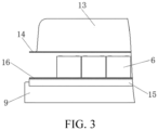
FIG. 3 is a schematic diagram of collaboration among a sealing cover, a battery module, a bus top frame, and a sealing surface in a new energy bus according to the present invention. - 1. Passenger region; 2. Passenger region top floor; 3. Bus top skin; 4. Liquid heat exchange plate opening; 5. Battery module; 6. Liquid heat exchange plate; 7. Bolt; 8. Mounting ear; 9. Bus top frame; 10. Blower; 11. Window body; 12. Chamber; 13. Sealing cover; 14. Sealing flange; 15. Sealing body; and 16. Sealing gasket.
- In order to make the objectives, technical solutions, and advantages of the invention clearer and more comprehensible, the invention is further described in detail in combination with the drawings and embodiments. It should be understood that the specific embodiments described herein serve to explain the invention merely and are not used to limit the invention. That is, the described embodiments are merely part of the embodiments, rather than all of the embodiments, of the invention. The components of the embodiments of the invention generally described and illustrated in the drawings herein may be arranged and designed in a variety of different configurations.
- Therefore, the following detailed description of the embodiments of the invention provided in the accompanying drawings is not intended to limit the scope of the invention as claimed, but is merely representative of selected embodiments of the invention. Based on the embodiments of the invention, all other embodiments obtained by a person having ordinary skill in the art without making any inventive effort fall within the scope that the invention seeks to protect.
- It should be noted that relational terms such as the terms "first" and "second" that may appear are only used to distinguish one entity or operation from another entity or operation, and do not necessarily require or imply any such actual relationship or order between these entities or operations. Moreover, the terms "including", "comprising", or any other variations thereof that may be provided, are intended to cover non-exclusive inclusion, so that a process, method, object, or device including a series of elements includes not only those elements, but also other elements that are not explicitly listed, or includes elements inherent to the process, method, object, or device. If there are no more restrictions, the element defined by the sentence "including a..." that may be provided, does not exclude in the process, method that includes the element.
- In the description of the invention, unless clearly specified and defined otherwise, the terms "mounted", "connected", and "connecting" that may appear should be understood in a broad sense, for instance, it can be a fixed connection, a detachable connection, or an integral connection, it can be a mechanical connection or an electrical connection, it can be a direct connection or indirect connection through an intermediate medium, or it can be the internal communication between two elements. For a person having ordinary skill in the art, the specific meaning of the above-mentioned terms in the invention can be understood through specific circumstances.
- In the description of the invention, it should be noted that unless clearly specified and defined otherwise, the term "provided with" that may appear should be construed in a broad sense. For instance, the object that is "provided" may be a part of the body, or it may be arranged separately from the body and connected to the body, and the connection may be a detachable connection or a non-detachable connection. For a person having ordinary skill in the art, the specific meaning of the above-mentioned terms in the invention can be understood through specific circumstances.
- The invention will be further described in detail below together with the embodiments.
- Specific embodiments of a new energy bus provided in the present invention are as follows:
As shown inFIG. 1 to FIG. 3 , the new energy bus includes a bus body. The bus body includes abus top frame 9 and abus top skin 3 located at a top portion. The bus body is provided with apassenger region 1 inside, a top portion of thepassenger region 1 is provided with a passenger regiontop floor 2, and the passenger regiontop floor 2 separates thebus top frame 9 from thepassenger region 1. - A battery module 5 is fixedly placed on the top portion of the bus body. The battery module 5 is formed by stacking battery cells. When the battery cells are stacked, the battery cells are placed right-side up and poles are arranged upward. A specific molding method of the battery module 5 may be bonded with a structural adhesive, or a plastic bracket, an end plate, a side plate, a binding strap, and the like. The molding method of the battery module 5 is the prior art and is not described in detail herein. A quantity of battery modules 5 is designed and changed according to an actual situation. The battery module 5 may be in a placement direction parallel to a traveling direction of the vehicle or perpendicular to a traveling direction of the vehicle, or be in a mixed placement. In other embodiments, the battery cells in the battery module 5 may be placed sideways or flat, and the poles are arranged toward a horizontal side.
- As shown in
FIG. 1 , first, the top portion of the bus body is fixedly provided with a liquidheat exchange plate 6. The liquidheat exchange plate 6 is provided with a liquid flow channel inside. A plate surface of the liquidheat exchange plate 6 is provided with liquid heatexchange plate openings 4 in communication with the liquid flow channel. Some of the liquid heatexchange plate openings 4 serve as coolant inlets, and the other liquid heatexchange plate openings 4 serve as coolant outlets. The air conditioning system is connected to the coolant inlet and the coolant outlet, and a coolant flows in the liquidheat exchange plate 6 to heat and cool the battery module 5. - The battery module 5 is fixed on a top surface of the liquid
heat exchange plate 6 through bonding by using the structural adhesive. Certainly, in other embodiments, the battery module 5 may be fixed on the liquidheat exchange plate 6 with a bolt, or a pressure plate is disposed to press the battery module 5 on the liquidheat exchange plate 6. - As shown in
FIG. 1 , to fixedly mount the liquidheat exchange plate 6 on the top portion of the bus body, the liquidheat exchange plate 6 is fixedly provided with a mountingear 8. The mountingear 8 may be welded to the liquidheat exchange plate 6, or may be integrally machined and molded with the liquidheat exchange plate 6. A quantity of mountingears 8 is selected according to a size of the liquidheat exchange plate 6 and a position of thebus top frame 9, and the mountingears 8 may be disposed on a left side and a right side or a front side and a rear side of the battery module 5. Generally, the quantity of mountingears 8 is greater than 6. Thebus top frame 9 is processed with threaded holes, and the mountingears 8 are provided with bolt through holes. During assembly, thebolts 7 run through the mountingears 8 and then run into the threaded holes of thebus top frame 9, and the mountingears 8 and the liquidheat exchange plate 6 are fixed on thebus top frame 9. When thebolts 7 are mounted, thebolts 7 run through thebus top skin 3. In other embodiments, nuts are pre-welded in thebus top frame 9, and thebolts 7 run into the pre-welded nuts of thebus top frame 9 for fixation. In other embodiments, the liquidheat exchange plate 6 may be mounted on thebus top frame 9 by welding or bayonet locking. In other embodiments, a cylinder is used to press and fix the liquidheat exchange plate 6 on thebus top frame 9. When disassembly for repair or replacement is required, quick disassembly may be achieved by disconnecting an air source of the cylinder. - An assembly sequence of the battery module 5, the
bus top frame 9, and the liquidheat exchange plate 6 may be flexibly selected. The battery module 5 and the liquidheat exchange plate 6 may be fixed offline first and then assembled onto thebus top frame 9 as a whole. Alternatively, the liquidheat exchange plate 6 may be fixed on thebus top frame 9 first, and then the battery module 5 is fixed on the liquidheat exchange plate 6. - A filling body is disposed between the
bus top skin 3 and the passenger regiontop floor 2. The filling body herein is a spacer plate or other fillers (not shown in the figure). The filling body is in a sealing fit with the liquidheat exchange plate 6 and the passenger regiontop floor 2 to form achamber 12, and the heat of the liquidheat exchange plate 6 can be transferred to thechamber 12. To increase the heat transferred between the liquidheat exchange plate 6 and thechamber 12, a position on thebus top skin 3 corresponding to the liquidheat exchange plate 6 is provided with an opening, so that thechamber 12 is directly communicated with the bottom surface of the liquidheat exchange plate 6. An area of the opening on thebus top skin 3 is greater than an area of the liquidheat exchange plate 6. In this case, the top portion of the spacer plate or filler is in a sealing abutment on the liquidheat exchange plate 6 to seal thechamber 12. In other embodiments, the area of the opening on thebus top skin 3 may be less than the area of the liquidheat exchange plate 6. In this case, the liquidheat exchange plate 6 is supported on thebus top skin 3, the sealing between the liquidheat exchange plate 6 and thebus top skin 3 is good, and the top portion of the filling body is in a sealing abutment on thebus top skin 3 to seal thechamber 12. A metal plate with a great heat transfer coefficient is selected as the liquidheat exchange plate 6. - As shown in
FIG. 1 , the passenger regiontop floor 2 is provided with a window. Through the window, thechamber 12 is communicated with thepassenger region 1. The passenger regiontop floor 2 is rotatably mounted with awindow body 11. Thewindow body 11 can block the window or can make way for the window. Ablower 10 is mounted in thechamber 12. Specifically, theblower 10 is mounted on the bottom surface of the liquidheat exchange plate 6. Theblower 10 directly faces the window up and down, and theblower 10 can blow air toward the window. The new energy bus is equipped with a motor and a controller for thewindow body 11. The motor is connected to thewindow body 11 and can drive the window body to block the window or make way for the window. The controller can control start and stop of the motor and a rotation direction. - As shown in
FIG. 2 andFIG. 3 , a sealingcover 13 is further mounted on the top portion of the bus body. The sealingcover 13 covers the battery module 5 and forms a sealed chamber together with the top portion of the bus body. The sealingcover 13 may be made of a composite material, a plastic material, or a metal material. The edge of the sealingcover 13 is provided with a sealingflange 14. The bottom portion of the sealingflange 14 is provided with a flat sealing surface. The sealingflange 14 is preset with through holes. - The top portion of the
bus top skin 3 corresponding to the sealingflange 14 is provided with a sealingbody 15. The sealingbody 15 herein is a metal profile welded to thebus top skin 3. The sealing between the metal profile and thebus top skin 3 is good, and the metal profile is processed with a threaded hole. The metal profile is fixedly provided with a sealinggasket 16. The sealinggasket 16 is made of an elastic material, which may be a silicone pad, a foam pad, or the like. During assembly, the bolt runs through the sealingflange 14 and then is screwed into the threaded hole of the metal profile. The sealinggasket 16 deforms under pressure to achieve sealing. Certainly, in other embodiments, a nut may be pre-welded on the metal profile to be in a sealing fit with a bolt. In other embodiments, the sealinggasket 16 may be omitted, the bottom surface of the sealingflange 14 and/or the top surface of the sealingbody 15 is provided with an adhesive storage groove, the sealingcover 13 and the sealingbody 15 are bonded and fixed together by filling the adhesive storage groove with a sealing adhesive, and the sealing performance is ensured. In other embodiments, the sealingbody 15 may be a plate welded to thebus top skin 3. In other embodiments, the sealingbody 15 may be directly a part of the bus top skin. In other embodiments, the sealinggasket 16 is disposed on the bottom surface of the sealingflange 14. In other embodiments, the sealingflange 14 is omitted, and the sealingcover 13 is directly mounted on the bus top by the structural adhesive. - The sealing
cover 13 and the top portion of the bus body form a sealed battery accommodating chamber, and the battery module 5 is located in the battery accommodating chamber. Compared with the method in the prior art of fixing the battery pack on the top portion of the bus body, there is no need to dispose a side plate, a top plate, and other structures of the battery pack, which saves materials, achieves lightweight, and saves space so that more battery modules 5 may be arranged in a limited space, which is beneficial to improving the endurance mileage of the new energy bus. - In this embodiment, the
passenger region 1 and thechamber 12 are connected through the window and thewindow body 11. When thepassenger region 1 and the battery module 5 both need to be cooled, the air conditioning system simultaneously cools the liquidheat exchange plate 6 and thepassenger region 1. The top surface of the liquidheat exchange plate 6 exchanges heat with the battery module 5 to cool the battery module 5, and the bottom surface of the liquidheat exchange plate 6 exchanges heat with thechamber 12 to cool thechamber 12. In this case, the controller controls the motor to open thewindow body 11, and theblower 10 transfers the cold air in thechamber 12 to thepassenger region 1. A same working process applies to a usage condition of heating. When only thepassenger region 1 or only the battery module 5 is cooled or heated, thewindow body 11 closes the window, and heat exchange between thepassenger region 1 and thechamber 12 is no longer performed. The disposition of thechamber 12, the window, and thewindow body 11 can prevent the cooling energy or heating energy at the bottom portion of the liquidheat exchange plate 6 from being dissipated in the air and cannot be effectively utilized, thereby improving the energy utilization of the entire vehicle. - In other embodiments, the
window body 11 is manually rotated, or thewindow body 11 may be detachably mounted on the passenger regiontop floor 2. - In other embodiments, the
bus top skin 3 remains intact, and thechamber 12 exchanges heat with the liquidheat exchange plate 6 through thebus top skin 3. Although the heat exchange efficiency is reduced, the heat utilization is still improved compared with the prior art. - Finally, it should be pointed out that the above description is only preferred embodiments of the invention and is not intended to limit the invention. Although the invention has been described in detail with reference to the above-mentioned examples, it is still possible for those skilled in the art to modify the technical means described in the above-mentioned examples without creative work, or to make equal substitutions of some or all of the technical configurations therein. Any modifications, equivalent substitutions, and improvements etc. made within the spirit and principle of the present invention shall fall within the protection scope of the present invention.
Claims (10)
- A new energy bus, comprising a bus body, the bus body comprising a bus top frame (9) located on a top portion, a bus top skin (3) covering a top portion of the bus top frame (9), and a passenger region top floor (2) located below the bus top frame (9), wherein the bus top frame (9) is fixedly provided with a liquid heat exchange plate (6), the liquid heat exchange plate (6) is provided with a coolant inlet and a coolant outlet that are connected to an air conditioning system, a top surface of the liquid heat exchange plate (6) is fixedly provided with a battery module (5), the bus top skin (3) is directly or indirectly mounted with a sealing cover (13) in a sealing manner covering an outer portion of the battery module (5), a filling body is disposed between the liquid heat exchange plate (6) and the passenger region top floor (2) and forms a sealed chamber (12) with the liquid heat exchange plate (6) and the passenger region top floor (2) in a surrounding manner, a position on the passenger region top floor (2) corresponding to the chamber (12) is provided with a window in communication with a passenger region (1), the window is provided with a window body (11) that opens and closes the window, and the chamber (12) is provided with a blower (10) inside for blowing air to the passenger region (1) through the window.
- The new energy bus according to claim 1, wherein the bus top skin (3) is provided with an opening at the chamber (12), so that the liquid heat exchange plate (6) is directly communicated with the chamber (12).
- The new energy bus according to claim 2, wherein a top portion of the filling body is in a sealing abutment on the liquid heat exchange plate (6), and a bottom portion of the filling body is in a sealing abutment on the passenger region top floor (2) to form the chamber (12); or the liquid heat exchange plate (6) is supported on the bus top skin (3) and is in a sealing fit with the bus top skin (3), a top portion of the filling body is in a sealing abutment on the bus top skin (3), and a bottom portion of the filling body is in a sealing abutment on the passenger region top floor (2) to form the chamber (12).
- The new energy bus according to claim 2, wherein the blower (10) is fixedly disposed on a bottom surface of the liquid heat exchange plate (6).
- The new energy bus according to claim 1, wherein the window body (11) is rotatably mounted on the passenger region top floor (2), the new energy bus comprises a motor that drives the window body (11) to rotate to open and close the window, the new energy bus further comprises a controller for controlling start and stop of the motor and a rotation direction, and the controller is configured to control the motor to open the window when both the battery module (5) and the passenger region (1) are cooled or heated and control the motor to close the window when only one of the battery module (5) and the passenger region (1) is cooled or heated.
- The new energy bus according to any one of claims 1 to 5, wherein an outer side of an edge of the liquid heat exchange plate (6) is provided with a mounting ear (8), and the mounting ear (8) is provided with a bolt through hole; the bus top frame (9) is provided with a threaded hole or pre-welded with a nut, the new energy bus comprises a bolt (7) running through the bolt through hole of the mounting ear (8) and screwed into the threaded hole or the nut, and the bolt (7) fixes the liquid heat exchange plate (6) on the bus top frame (9).
- The new energy bus according to any one of claims 1 to 5, wherein an edge position of the sealing cover (13) is provided with a sealing flange (14), one of a bottom surface of the sealing flange (14) and a top surface of the bus top skin (3) is provided with a sealing gasket (16), the sealing flange (14) is provided with a bolt through hole, the bus top skin (3) is provided with a threaded hole or pre-welded with a nut, the new energy bus comprises a bolt (7) running through the bolt through hole of the sealing flange (14) and screwed into the threaded hole or the nut on the bus top skin (3), the bolt (7) fixes the sealing flange (14) on the bus top skin (3), and the elastic deformation of sealing gasket (16) is to ensure sealing performance between the sealing flange (14) and the bus top skin (3).
- The new energy bus according to any one of claims 1 to 5, wherein an edge position of the sealing cover (13) is provided with a sealing flange (14), a position on the bus top skin (3) corresponding to the sealing flange (14) is welded with a sealing body (15), one of a bottom surface of the sealing flange (14) and a top surface of the sealing body (15) is provided with a sealing gasket (16), the sealing flange (14) is provided with a bolt through hole, the sealing body (15) is provided with a threaded hole or pre-welded with a nut, the new energy bus comprises a bolt (7) running through the bolt through hole of the sealing flange (14) and screwed into the threaded hole or the nut on the sealing body (15), the bolt (7) fixes the sealing flange (14) on the sealing body (15), and the elastic deformation of sealing gasket (16) is to ensure sealing performance between the sealing flange (14) and the sealing body (15).
- The new energy bus according to any one of claims 1 to 5, wherein an edge position of the sealing cover (13) is provided with a sealing flange (14), a top surface of the sealing flange (14) and/or a bottom surface of the bus top skin (3) is provided with an adhesive storage groove, and the adhesive storage groove is configured to store a sealing adhesive to bond the sealing flange (14) and the bus top skin (3) together and ensure sealing performance between the sealing flange (14) and the bus top skin (3).
- The new energy bus according to any one of claims 1 to 5, wherein an edge position of the sealing cover (13) is provided with a sealing flange (14), a position on the bus top skin (3) corresponding to the sealing flange (14) is welded with a sealing body (15), a bottom surface of the sealing flange (14) and/or a top surface of the sealing body (15) is provided with an adhesive storage groove, and the adhesive storage groove is configured to store a sealing adhesive to bond the sealing flange (14) and the sealing body (15) together and ensure sealing performance between the sealing flange (14) and the sealing body (15).
Applications Claiming Priority (2)
| Application Number | Priority Date | Filing Date | Title |
|---|---|---|---|
| CN202210593416.3A CN116691305A (en) | 2022-05-27 | 2022-05-27 | New energy bus |
| PCT/CN2022/113475 WO2023226211A1 (en) | 2022-05-27 | 2022-08-19 | New energy bus |
Publications (4)
| Publication Number | Publication Date |
|---|---|
| EP4375103A1 true EP4375103A1 (en) | 2024-05-29 |
| EP4375103A4 EP4375103A4 (en) | 2024-12-25 |
| EP4375103B1 EP4375103B1 (en) | 2025-05-28 |
| EP4375103C0 EP4375103C0 (en) | 2025-05-28 |
Family
ID=87826350
Family Applications (1)
| Application Number | Title | Priority Date | Filing Date |
|---|---|---|---|
| EP22943401.4A Active EP4375103B1 (en) | 2022-05-27 | 2022-08-19 | New energy bus |
Country Status (3)
| Country | Link |
|---|---|
| EP (1) | EP4375103B1 (en) |
| CN (1) | CN116691305A (en) |
| WO (1) | WO2023226211A1 (en) |
Families Citing this family (1)
| Publication number | Priority date | Publication date | Assignee | Title |
|---|---|---|---|---|
| CN120791216B (en) * | 2025-09-11 | 2025-12-09 | 湖南联诚轨道装备有限公司 | Aluminum alloy top cover and welding deformation control method thereof |
Family Cites Families (9)
| Publication number | Priority date | Publication date | Assignee | Title |
|---|---|---|---|---|
| DE102008056064A1 (en) * | 2008-11-05 | 2010-05-06 | Daimler Ag | Energy device for generating electric power fits on a vehicle's roof like the roof of a omnibus with a fuel-cell system having an air-supply/pneumatic-system device and a fuel cell |
| CN206201949U (en) | 2016-10-31 | 2017-05-31 | 比亚迪股份有限公司 | A kind of battery mounting framework and battery case and electric motor coach |
| JP2018075945A (en) * | 2016-11-09 | 2018-05-17 | 株式会社Ihi | Battery cooling mechanism and moving vehicle |
| CN110682763B (en) * | 2018-07-06 | 2024-02-20 | 宇通客车股份有限公司 | A passenger car based on fuel cell waste heat utilization |
| CN208602349U (en) * | 2018-08-08 | 2019-03-15 | 厦门金龙汽车空调有限公司 | A kind of electric motor coach integrated battery cooled air-conditioning system |
| CN210591284U (en) * | 2019-06-27 | 2020-05-22 | 上海申龙客车有限公司 | New forms of energy passenger train overhead thermal control system |
| CN110224201A (en) * | 2019-07-10 | 2019-09-10 | 厦门金龙联合汽车工业有限公司 | A kind of power battery cooling system and its application method of new energy bus |
| CN210234715U (en) * | 2019-07-25 | 2020-04-03 | 上海加冷松芝汽车空调股份有限公司 | Overhead battery thermal management device |
| CN112918566A (en) * | 2021-04-30 | 2021-06-08 | 厦门金龙联合汽车工业有限公司 | New forms of energy passenger train's top cap assembly |
-
2022
- 2022-05-27 CN CN202210593416.3A patent/CN116691305A/en active Pending
- 2022-08-19 EP EP22943401.4A patent/EP4375103B1/en active Active
- 2022-08-19 WO PCT/CN2022/113475 patent/WO2023226211A1/en not_active Ceased
Also Published As
| Publication number | Publication date |
|---|---|
| EP4375103A4 (en) | 2024-12-25 |
| WO2023226211A1 (en) | 2023-11-30 |
| CN116691305A (en) | 2023-09-05 |
| EP4375103B1 (en) | 2025-05-28 |
| EP4375103C0 (en) | 2025-05-28 |
Similar Documents
| Publication | Publication Date | Title |
|---|---|---|
| CN204537864U (en) | A kind of super capacitor module box body and use the super capacitor module of this casing | |
| CN102544625A (en) | Cooling device of semiconductor water-cooling battery | |
| CN206602729U (en) | The motor controller box body of pure electronic logistic car | |
| EP4375103B1 (en) | New energy bus | |
| CN211017195U (en) | An electric vehicle power battery pack | |
| CN210628372U (en) | Power battery pack and vehicle with same | |
| CN106450567A (en) | Thermal management system for electric vehicle battery | |
| CN115528367A (en) | New energy automobile battery system with efficient heat dissipation function and heat dissipation method | |
| CN208797084U (en) | A kind of power battery pack | |
| CN220492051U (en) | Box assembly, battery and electric equipment | |
| CN219226506U (en) | Battery pack and vehicle | |
| CN216389519U (en) | Power battery heat radiation structure of dump truck in electric yard | |
| CN115149169A (en) | Battery package and car | |
| CN213816329U (en) | Unmanned battery system of new energy automobile | |
| CN210948879U (en) | Generating set with good heat dissipation effect | |
| CN112582728A (en) | Wind-liquid integrated thermal management battery system of electric motorcycle | |
| CN219476785U (en) | Battery modules and battery systems and electric vehicles | |
| CN216161873U (en) | New energy automobile battery is with storing box | |
| CN217062323U (en) | Novel automobile power battery system and novel electric automobile using same | |
| CN214450417U (en) | Battery thermal management system of pure electric vehicle | |
| CN223583044U (en) | A battery pack and liquid-cooled energy storage system | |
| CN221530051U (en) | Electric motorcycle battery pack with efficient thermal management system | |
| CN220796858U (en) | Air cooling circulation system of battery energy storage cabin | |
| CN223842982U (en) | Battery devices, energy storage devices and electrical appliances | |
| CN222690809U (en) | Electric vehicle battery box and electric vehicle |
Legal Events
| Date | Code | Title | Description |
|---|---|---|---|
| STAA | Information on the status of an ep patent application or granted ep patent |
Free format text: STATUS: THE INTERNATIONAL PUBLICATION HAS BEEN MADE |
|
| PUAI | Public reference made under article 153(3) epc to a published international application that has entered the european phase |
Free format text: ORIGINAL CODE: 0009012 |
|
| STAA | Information on the status of an ep patent application or granted ep patent |
Free format text: STATUS: REQUEST FOR EXAMINATION WAS MADE |
|
| 17P | Request for examination filed |
Effective date: 20240219 |
|
| AK | Designated contracting states |
Kind code of ref document: A1 Designated state(s): AL AT BE BG CH CY CZ DE DK EE ES FI FR GB GR HR HU IE IS IT LI LT LU LV MC MK MT NL NO PL PT RO RS SE SI SK SM TR |
|
| A4 | Supplementary search report drawn up and despatched |
Effective date: 20241122 |
|
| RIC1 | Information provided on ipc code assigned before grant |
Ipc: H01M 10/6567 20140101ALI20241118BHEP Ipc: H01M 10/655 20140101ALI20241118BHEP Ipc: H01M 50/24 20210101ALI20241118BHEP Ipc: H01M 10/6568 20140101ALI20241118BHEP Ipc: H01M 10/6556 20140101ALI20241118BHEP Ipc: H01M 10/625 20140101ALI20241118BHEP Ipc: H01M 10/615 20140101ALI20241118BHEP Ipc: H01M 10/613 20140101ALI20241118BHEP Ipc: B60L 58/27 20190101ALI20241118BHEP Ipc: B60L 58/26 20190101ALI20241118BHEP Ipc: B60L 50/60 20190101ALI20241118BHEP Ipc: B60L 50/64 20190101ALI20241118BHEP Ipc: B60K 1/00 20060101ALI20241118BHEP Ipc: B60H 1/00 20060101ALI20241118BHEP Ipc: B60K 1/04 20190101AFI20241118BHEP |
|
| GRAP | Despatch of communication of intention to grant a patent |
Free format text: ORIGINAL CODE: EPIDOSNIGR1 |
|
| STAA | Information on the status of an ep patent application or granted ep patent |
Free format text: STATUS: GRANT OF PATENT IS INTENDED |
|
| DAV | Request for validation of the european patent (deleted) | ||
| DAX | Request for extension of the european patent (deleted) | ||
| INTG | Intention to grant announced |
Effective date: 20250128 |
|
| GRAS | Grant fee paid |
Free format text: ORIGINAL CODE: EPIDOSNIGR3 |
|
| GRAA | (expected) grant |
Free format text: ORIGINAL CODE: 0009210 |
|
| STAA | Information on the status of an ep patent application or granted ep patent |
Free format text: STATUS: THE PATENT HAS BEEN GRANTED |
|
| AK | Designated contracting states |
Kind code of ref document: B1 Designated state(s): AL AT BE BG CH CY CZ DE DK EE ES FI FR GB GR HR HU IE IS IT LI LT LU LV MC MK MT NL NO PL PT RO RS SE SI SK SM TR |
|
| REG | Reference to a national code |
Ref country code: GB Ref legal event code: FG4D |
|
| REG | Reference to a national code |
Ref country code: CH Ref legal event code: EP |
|
| REG | Reference to a national code |
Ref country code: IE Ref legal event code: FG4D Ref country code: DE Ref legal event code: R096 Ref document number: 602022015309 Country of ref document: DE |
|
| U01 | Request for unitary effect filed |
Effective date: 20250624 |
|
| U07 | Unitary effect registered |
Designated state(s): AT BE BG DE DK EE FI FR IT LT LU LV MT NL PT RO SE SI Effective date: 20250701 |
|
| U20 | Renewal fee for the european patent with unitary effect paid |
Year of fee payment: 4 Effective date: 20250828 |
|
| PG25 | Lapsed in a contracting state [announced via postgrant information from national office to epo] |
Ref country code: ES Free format text: LAPSE BECAUSE OF FAILURE TO SUBMIT A TRANSLATION OF THE DESCRIPTION OR TO PAY THE FEE WITHIN THE PRESCRIBED TIME-LIMIT Effective date: 20250528 |
|
| PG25 | Lapsed in a contracting state [announced via postgrant information from national office to epo] |
Ref country code: NO Free format text: LAPSE BECAUSE OF FAILURE TO SUBMIT A TRANSLATION OF THE DESCRIPTION OR TO PAY THE FEE WITHIN THE PRESCRIBED TIME-LIMIT Effective date: 20250828 Ref country code: GR Free format text: LAPSE BECAUSE OF FAILURE TO SUBMIT A TRANSLATION OF THE DESCRIPTION OR TO PAY THE FEE WITHIN THE PRESCRIBED TIME-LIMIT Effective date: 20250829 |
|
| PG25 | Lapsed in a contracting state [announced via postgrant information from national office to epo] |
Ref country code: PL Free format text: LAPSE BECAUSE OF FAILURE TO SUBMIT A TRANSLATION OF THE DESCRIPTION OR TO PAY THE FEE WITHIN THE PRESCRIBED TIME-LIMIT Effective date: 20250528 |
|
| PG25 | Lapsed in a contracting state [announced via postgrant information from national office to epo] |
Ref country code: HR Free format text: LAPSE BECAUSE OF FAILURE TO SUBMIT A TRANSLATION OF THE DESCRIPTION OR TO PAY THE FEE WITHIN THE PRESCRIBED TIME-LIMIT Effective date: 20250528 |
|
| PG25 | Lapsed in a contracting state [announced via postgrant information from national office to epo] |
Ref country code: RS Free format text: LAPSE BECAUSE OF FAILURE TO SUBMIT A TRANSLATION OF THE DESCRIPTION OR TO PAY THE FEE WITHIN THE PRESCRIBED TIME-LIMIT Effective date: 20250828 |
|
| PG25 | Lapsed in a contracting state [announced via postgrant information from national office to epo] |
Ref country code: IS Free format text: LAPSE BECAUSE OF FAILURE TO SUBMIT A TRANSLATION OF THE DESCRIPTION OR TO PAY THE FEE WITHIN THE PRESCRIBED TIME-LIMIT Effective date: 20250928 |
|
| PG25 | Lapsed in a contracting state [announced via postgrant information from national office to epo] |
Ref country code: SM Free format text: LAPSE BECAUSE OF FAILURE TO SUBMIT A TRANSLATION OF THE DESCRIPTION OR TO PAY THE FEE WITHIN THE PRESCRIBED TIME-LIMIT Effective date: 20250528 |
|
| PG25 | Lapsed in a contracting state [announced via postgrant information from national office to epo] |
Ref country code: CZ Free format text: LAPSE BECAUSE OF FAILURE TO SUBMIT A TRANSLATION OF THE DESCRIPTION OR TO PAY THE FEE WITHIN THE PRESCRIBED TIME-LIMIT Effective date: 20250528 |
|
| PG25 | Lapsed in a contracting state [announced via postgrant information from national office to epo] |
Ref country code: SK Free format text: LAPSE BECAUSE OF FAILURE TO SUBMIT A TRANSLATION OF THE DESCRIPTION OR TO PAY THE FEE WITHIN THE PRESCRIBED TIME-LIMIT Effective date: 20250528 |
|
| REG | Reference to a national code |
Ref country code: CH Ref legal event code: H13 Free format text: ST27 STATUS EVENT CODE: U-0-0-H10-H13 (AS PROVIDED BY THE NATIONAL OFFICE) Effective date: 20260324 |
|
| PG25 | Lapsed in a contracting state [announced via postgrant information from national office to epo] |
Ref country code: MC Free format text: LAPSE BECAUSE OF FAILURE TO SUBMIT A TRANSLATION OF THE DESCRIPTION OR TO PAY THE FEE WITHIN THE PRESCRIBED TIME-LIMIT Effective date: 20250528 |
|
| PLBE | No opposition filed within time limit |
Free format text: ORIGINAL CODE: 0009261 |
|
| STAA | Information on the status of an ep patent application or granted ep patent |
Free format text: STATUS: NO OPPOSITION FILED WITHIN TIME LIMIT |
|
| REG | Reference to a national code |
Ref country code: CH Ref legal event code: L10 Free format text: ST27 STATUS EVENT CODE: U-0-0-L10-L00 (AS PROVIDED BY THE NATIONAL OFFICE) Effective date: 20260409 |
|
| PG25 | Lapsed in a contracting state [announced via postgrant information from national office to epo] |
Ref country code: CH Free format text: LAPSE BECAUSE OF NON-PAYMENT OF DUE FEES Effective date: 20250831 |