EP4375089A1 - Tire - Google Patents
Tire Download PDFInfo
- Publication number
- EP4375089A1 EP4375089A1 EP23208871.6A EP23208871A EP4375089A1 EP 4375089 A1 EP4375089 A1 EP 4375089A1 EP 23208871 A EP23208871 A EP 23208871A EP 4375089 A1 EP4375089 A1 EP 4375089A1
- Authority
- EP
- European Patent Office
- Prior art keywords
- sipe
- wide portion
- tire
- cross
- width
- Prior art date
- Legal status (The legal status is an assumption and is not a legal conclusion. Google has not performed a legal analysis and makes no representation as to the accuracy of the status listed.)
- Granted
Links
Images






Classifications
-
- B—PERFORMING OPERATIONS; TRANSPORTING
- B60—VEHICLES IN GENERAL
- B60C—VEHICLE TYRES; TYRE INFLATION; TYRE CHANGING; CONNECTING VALVES TO INFLATABLE ELASTIC BODIES IN GENERAL; DEVICES OR ARRANGEMENTS RELATED TO TYRES
- B60C11/00—Tyre tread bands; Tread patterns; Anti-skid inserts
- B60C11/03—Tread patterns
-
- B—PERFORMING OPERATIONS; TRANSPORTING
- B60—VEHICLES IN GENERAL
- B60C—VEHICLE TYRES; TYRE INFLATION; TYRE CHANGING; CONNECTING VALVES TO INFLATABLE ELASTIC BODIES IN GENERAL; DEVICES OR ARRANGEMENTS RELATED TO TYRES
- B60C11/00—Tyre tread bands; Tread patterns; Anti-skid inserts
- B60C11/03—Tread patterns
- B60C11/0306—Patterns comprising block rows or discontinuous ribs
-
- B—PERFORMING OPERATIONS; TRANSPORTING
- B60—VEHICLES IN GENERAL
- B60C—VEHICLE TYRES; TYRE INFLATION; TYRE CHANGING; CONNECTING VALVES TO INFLATABLE ELASTIC BODIES IN GENERAL; DEVICES OR ARRANGEMENTS RELATED TO TYRES
- B60C11/00—Tyre tread bands; Tread patterns; Anti-skid inserts
- B60C11/03—Tread patterns
- B60C11/0327—Tread patterns characterised by special properties of the tread pattern
-
- B—PERFORMING OPERATIONS; TRANSPORTING
- B60—VEHICLES IN GENERAL
- B60C—VEHICLE TYRES; TYRE INFLATION; TYRE CHANGING; CONNECTING VALVES TO INFLATABLE ELASTIC BODIES IN GENERAL; DEVICES OR ARRANGEMENTS RELATED TO TYRES
- B60C11/00—Tyre tread bands; Tread patterns; Anti-skid inserts
- B60C11/03—Tread patterns
- B60C11/12—Tread patterns characterised by the use of narrow slits or incisions, e.g. sipes
- B60C11/1204—Tread patterns characterised by the use of narrow slits or incisions, e.g. sipes with special shape of the sipe
-
- B—PERFORMING OPERATIONS; TRANSPORTING
- B60—VEHICLES IN GENERAL
- B60C—VEHICLE TYRES; TYRE INFLATION; TYRE CHANGING; CONNECTING VALVES TO INFLATABLE ELASTIC BODIES IN GENERAL; DEVICES OR ARRANGEMENTS RELATED TO TYRES
- B60C11/00—Tyre tread bands; Tread patterns; Anti-skid inserts
- B60C11/03—Tread patterns
- B60C11/12—Tread patterns characterised by the use of narrow slits or incisions, e.g. sipes
- B60C11/1204—Tread patterns characterised by the use of narrow slits or incisions, e.g. sipes with special shape of the sipe
- B60C11/1218—Three-dimensional shape with regard to depth and extending direction
-
- B—PERFORMING OPERATIONS; TRANSPORTING
- B60—VEHICLES IN GENERAL
- B60C—VEHICLE TYRES; TYRE INFLATION; TYRE CHANGING; CONNECTING VALVES TO INFLATABLE ELASTIC BODIES IN GENERAL; DEVICES OR ARRANGEMENTS RELATED TO TYRES
- B60C11/00—Tyre tread bands; Tread patterns; Anti-skid inserts
- B60C11/03—Tread patterns
- B60C11/12—Tread patterns characterised by the use of narrow slits or incisions, e.g. sipes
- B60C11/1259—Depth of the sipe
- B60C11/1263—Depth of the sipe different within the same sipe
-
- B—PERFORMING OPERATIONS; TRANSPORTING
- B60—VEHICLES IN GENERAL
- B60C—VEHICLE TYRES; TYRE INFLATION; TYRE CHANGING; CONNECTING VALVES TO INFLATABLE ELASTIC BODIES IN GENERAL; DEVICES OR ARRANGEMENTS RELATED TO TYRES
- B60C11/00—Tyre tread bands; Tread patterns; Anti-skid inserts
- B60C11/03—Tread patterns
- B60C11/12—Tread patterns characterised by the use of narrow slits or incisions, e.g. sipes
- B60C11/1272—Width of the sipe
- B60C11/1281—Width of the sipe different within the same sipe, i.e. enlarged width portion at sipe bottom or along its length
-
- B—PERFORMING OPERATIONS; TRANSPORTING
- B60—VEHICLES IN GENERAL
- B60C—VEHICLE TYRES; TYRE INFLATION; TYRE CHANGING; CONNECTING VALVES TO INFLATABLE ELASTIC BODIES IN GENERAL; DEVICES OR ARRANGEMENTS RELATED TO TYRES
- B60C11/00—Tyre tread bands; Tread patterns; Anti-skid inserts
- B60C11/03—Tread patterns
- B60C11/13—Tread patterns characterised by the groove cross-section, e.g. for buttressing or preventing stone-trapping
-
- B—PERFORMING OPERATIONS; TRANSPORTING
- B60—VEHICLES IN GENERAL
- B60C—VEHICLE TYRES; TYRE INFLATION; TYRE CHANGING; CONNECTING VALVES TO INFLATABLE ELASTIC BODIES IN GENERAL; DEVICES OR ARRANGEMENTS RELATED TO TYRES
- B60C11/00—Tyre tread bands; Tread patterns; Anti-skid inserts
- B60C11/0041—Tyre tread bands; Tread patterns; Anti-skid inserts comprising different tread rubber layers
- B60C11/005—Tyre tread bands; Tread patterns; Anti-skid inserts comprising different tread rubber layers with cap and base layers
-
- B—PERFORMING OPERATIONS; TRANSPORTING
- B60—VEHICLES IN GENERAL
- B60C—VEHICLE TYRES; TYRE INFLATION; TYRE CHANGING; CONNECTING VALVES TO INFLATABLE ELASTIC BODIES IN GENERAL; DEVICES OR ARRANGEMENTS RELATED TO TYRES
- B60C11/00—Tyre tread bands; Tread patterns; Anti-skid inserts
- B60C11/0008—Tyre tread bands; Tread patterns; Anti-skid inserts characterised by the tread rubber
- B60C2011/0016—Physical properties or dimensions
-
- B—PERFORMING OPERATIONS; TRANSPORTING
- B60—VEHICLES IN GENERAL
- B60C—VEHICLE TYRES; TYRE INFLATION; TYRE CHANGING; CONNECTING VALVES TO INFLATABLE ELASTIC BODIES IN GENERAL; DEVICES OR ARRANGEMENTS RELATED TO TYRES
- B60C11/00—Tyre tread bands; Tread patterns; Anti-skid inserts
- B60C11/03—Tread patterns
- B60C2011/0337—Tread patterns characterised by particular design features of the pattern
- B60C2011/0339—Grooves
- B60C2011/0341—Circumferential grooves
-
- B—PERFORMING OPERATIONS; TRANSPORTING
- B60—VEHICLES IN GENERAL
- B60C—VEHICLE TYRES; TYRE INFLATION; TYRE CHANGING; CONNECTING VALVES TO INFLATABLE ELASTIC BODIES IN GENERAL; DEVICES OR ARRANGEMENTS RELATED TO TYRES
- B60C11/00—Tyre tread bands; Tread patterns; Anti-skid inserts
- B60C11/03—Tread patterns
- B60C2011/0337—Tread patterns characterised by particular design features of the pattern
- B60C2011/0339—Grooves
- B60C2011/0358—Lateral grooves, i.e. having an angle of 45 to 90 degees to the equatorial plane
-
- B—PERFORMING OPERATIONS; TRANSPORTING
- B60—VEHICLES IN GENERAL
- B60C—VEHICLE TYRES; TYRE INFLATION; TYRE CHANGING; CONNECTING VALVES TO INFLATABLE ELASTIC BODIES IN GENERAL; DEVICES OR ARRANGEMENTS RELATED TO TYRES
- B60C11/00—Tyre tread bands; Tread patterns; Anti-skid inserts
- B60C11/03—Tread patterns
- B60C11/12—Tread patterns characterised by the use of narrow slits or incisions, e.g. sipes
- B60C11/1204—Tread patterns characterised by the use of narrow slits or incisions, e.g. sipes with special shape of the sipe
- B60C2011/1213—Tread patterns characterised by the use of narrow slits or incisions, e.g. sipes with special shape of the sipe sinusoidal or zigzag at the tread surface
Definitions
- the present invention relates to a tire.
- Patent Document 1 discloses a pneumatic tire intended for use in the winter season.
- an outside shoulder land portion is divided into a plurality of outside shoulder blocks by a plurality of outside shoulder lateral grooves extending in the tire axial direction.
- the outside shoulder block is divided by a narrow groove extending in the tire circumferential direction into a first block piece on the outside tread edge side and a second block piece on the inside tread edge side.
- the first block piece is provided with first sipes
- the second block piece is provided with second sipes.
- the total number of the second sipes of the second block piece is greater than the total number of the first sipes of the first block piece.
- Patent Document 1 Japanese Patent Application Publication No.2021-195051
- the present invention was made, and a primary objective thereof is to provide a tire with improved on-ice performance and loading durability while ensuring mold releasability.
- a tire comprises a tread portion provided with a plurality of circumferential grooves extending continuously in a tire circumferential direction, a plurality of lateral grooves extending in a tire axial direction, and a plurality of first blocks, wherein
- the tire can be improved in on-ice performance and the loading durability, while ensuring the mold releasability.
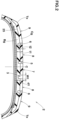
- Fig.1 is a developed partial view of a tread portion 2 of a tire 1 as an embodiment of the present invention.
- the tire 1 of the present invention shown in Fig.1 is intended for use in winter.
- the tire 1 is designed as a pneumatic tire for passenger cars.
- the present invention is however, not limited to such pneumatic tire, and may be applied, for example, to heavy duty tires.
- the tread portion 2 comprises a plurality of circumferential grooves 3 continuously extending in the tire circumferential direction between two tread edges Te, and a plurality of land portions 4 axially divided by these circumferential grooves 3.
- the tread edge Te corresponds to the outermost contact position in the tire axial direction when the tire 1 in its normal state is contact with a flat horizontal surface at a camber angle of 0 degrees and loaded with 70% of a normal load therefor.
- the "normal state” is a state of a tire in which the tire is mounted on a regular rim, inflated to a normal internal pressure, and loaded with no tire load.
- the "normal state” means a standard usage state according to the purpose of use of the tire, and a state in which the tire is not mounted on the vehicle and no load is applied.
- the “regular rim” means a wheel rim specified for the tire by a standard system including standards on which the tire is based, for example, "standard Rim” in JATMA, "Design Rim” in TRA and “Measuring Rim” in ETRTO.
- the "normal internal pressure” is the air pressure specified for the tire by a standard system including standards on which the tire is based, for example, the maximum air pressure in JATMA, the maximum value listed in the table "TIRE LOAD LIMITS AT VARIOUS COLD INFLATION PRESSURES" in TRA, and the "Inflation Pressure” in ETRTO.
- the "normal load” is a tire load specified for the tire by a standard system including standards on which the tire is based, for extreme, the maximum load capacity in JATMA, the maximum value listed in the table "TIRE LOAD LIMITS AT VARIOUS COLD INFLATION PRESSURES" in TRA, and the load capacity in ETRTO.
- the "normal load” is the maximum load which can be applied to the tire when used.
- the tread portion 2 in the present embodiment is provided with four circumferential grooves 3: two crown circumferential grooves 5 and two shoulder circumferential grooves 6.
- the two crown circumferential grooves 5 are arranged so as to sandwich the tire equator C.
- the two shoulder circumferential grooves 6 are arranged so as to sandwich the two crown circumferential grooves 5.
- the present invention is however, not limited to such groove arrangement.
- circumferential grooves 3 various mode, for example, straight grooves, zigzag grooves and the like may be adopted.
- Fig.2 conceptually shows a cross section of the tread portion 2, and cross sections of sipes and lateral grooves observed in a plan view of the tread portion 2 are omitted in Fig.2 .
- the groove widths of the circumferential grooves 3 are preferably at least 3 mm.
- the maximum groove width W1 among the circumferential grooves 3 is, for example, 2.0% to 5.0% of the tread width TW (shown in Fig.1 ).
- the maximum depth d1 among the circumferential grooves 3 is, for example, 5 to 15 mm.
- the tread width Tw corresponds to the distance in the tire axial direction from one tread edge Te to the other tread edge Te under the normal state.
- the tread portion 2 in the present embodiment is axially divided into five land portions 4: one crown land portion 7, two middle land portions 8, and two shoulder land portions 9.
- the crown land portion 7 is defined between the two crown circumferential grooves 5.
- Each of the middle land portion 8 is defined between one of the two crown circumferential groove 5 and one of the two shoulder circumferential groove 6.
- Each of the shoulder land portion 9 is defined between one of the shoulder circumferential grooves 6 and the adjacent tread edge Te.
- the tread portion 2 in the present embodiment is provided with a plurality of lateral grooves 10.
- each of the land portions 4 is circumferentially divided into a row of plurality of blocks 11.
- the blocks 11 include first blocks 13 in the shoulder land portions 9 forming the tread edges Te.
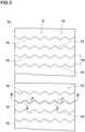
- Each of the first blocks 13 is provided with at least one first sipe 15.
- each of the first blocks 13 is provided with a plurality of first sipes 15 as shown in Fig.3 which shows, for example, two of the circumferentially adjacent first blocks 13 in the shoulder land portion 9 on the left side of Fig.1 .
- peel refers to means a narrow groove having a width not more than 1.5 mm between two opposite inner walls inclusive of a cut having no substantial width.
- Such a sipe may be provided with a chamfer at one of or each of the opening edges.
- the first sipe 15 communicates with a wide portion as described later.
- Fig.4 conceptually shows the interior space of the first sipe 15, wherein the interior space is lightly dotted.
- Fig.5 shows a cross section of the first sipe 15 and a cross section of a first wide portion 21 taken orthogonal to the sipe length direction, corresponding to a cross-sectional view taken along line AA in Fig.3 .
- Fig.6 shows a cross section of the first sipe shown in Fig.3 taken along a plane parallel to the ground contacting top surface of the first block 13.
- the first sipe 15 in the present embodiment extends in a zigzag shape in a cross section orthogonal to the sipe length direction, and extends in a zigzag shape in a cross section parallel to the ground contacting top surface of the first block 13.
- Fig.7 shows a cross section of the first sipe 15 taken along its length direction, corresponding to a cross-sectional view taken along line BB of Fig.3 .
- ridge and valley lines 20 partitioning convexes and concaves formed in the two opposite inner walls are shown by two-dot chain lines.
- the first sipe 15 is provided with at least one tie bar 18, and thereby partially divided (near the bottom) in the length direction of the sipe into at least a first portion 16 and a second portion 17.
- the tie bar 18 locally protrudes outward in a tire radial direction from the sipe bottom (in this example, from the bottoms of the wide portions 21 and 22) and terminates without reaching the ground contacting top surface 13s of the first block 13.
- the portion of the first sipe 15 between the radially outer end of the tie bar 18 and the ground contacting top surface 13s of the first block 13, is virtually divided into two portions which is explained hereunder as being included in the first portion 16 and the second portion, respectively.
- the first wide portion 21 communicates with the sipe bottom 16d of the first portion 16. As shown in Fig.5 , the first wide portion 21 has a groove width larger than the sipe width in the first portion 16.
- a second wide portion 22 communicates with the sipe bottom 17d of the second portion 17.
- the second wide portion 22 has a groove width larger than the sipe width in the second portion 17.
- the configuration of the first wide portion 21 can be applied to the second wide portion 22.
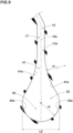
- Fig.8 is an enlarged cross-sectional view of the first wide portion 21 shown in Fig.5 .
- the first wide portion 21 comprises an outer portion 31 in the tire radial direction and an inner portion 32 in the tire radial direction at least.
- the outer portion 31 is formed by a pair of opposite first arcuate groove wall portions 31a which are convex toward a center line 15c of the first sipe 15 so that the groove width of the outer portion 31 continuously increases inward in the tire radial direction from the sipe bottom 16d of the first portion 16.
- the center line 15c is a center line in the width direction of the first sipe 15 which is extended to the bottom of the first wide portion 21.
- the inner portion 32 is formed by a pair of opposite second arcuate groove wall portions 32a convex toward the opposite side to the center line 15c of the first sipe 15 so that the groove width continuously decreases inward in the tire radial direction to the bottom of the first wide portion 21.
- the first wide portion 21 and the second wide portion 22 do not communicate with each other.
- the tire 1 of the present embodiment can be improve in on-ice performance and loading durability while ensuring the mold releasability.
- the reason is as follows.
- the first sipe 15 extends zigzag as described above. Further, the first sipe 15 is divided into the first portion 16 and the second portion 17 by the tie bar 18.
- tie bars 18 helps to maintain the rigidity of the first block 13.
- the collapse of the first block 13 is effectively suppressed; the strain at the sipe bottom of the first sipe 15 can be suppressed; and the loading durability is improved.
- the first sipe 15 communicates with the first wide portion 21 and the second wide portion 22 which are not in communication with each other.
- the first block 13 is prevented from collapsing by the mechanism described above, it is possible to ensure a large ground contact area when traveling on ice, and to obtain a large frictional force on ice due to the edge effect of the first sipe 15.
- the first sipe 15 communicates the first wide portion 21 and the second wide portion 22, the first sipe 15 exhibits excellent water absorption performance, which further enhances on-ice performance.
- the outer portion 31 is formed by the first arcuate groove wall portions 31a and the inner portion 32 is formed by the second arcuate groove wall portions 32a, the thick tip portion of a knife blade which forms the first wide portion 21 can be smoothly taken out from through the sipe during vulcanization molding, therefore, the mold releasability can be ensured.
- the tire 1 of the present embodiment can be improved in on-ice performance and loading durability while ensuring mold releasability.
- the tread portion 2 when the tread portion 2 is axially divided into four equal parts, namely, two axially outer parts 2A and two axially inner parts 2B, it is preferable that the above-described first blocks 13 disposed in the land portion 4 included in the axially outer parts 2A as shown in Fig.1 .
- the first blocks 13 are disposed in the shoulder land portion 9 as the blocks 11 thereof, and the first blocks 13 forms the tread edges Te.
- first sipes 15 are provided per first block 13 as shown in Fig.3 .
- first sipes 15 are provided per first block 13.
- Each of the four first sipes 15 extends across the first block 13 in the tire axial direction.
- the first block 13 may be provided with a narrow grooves extending in the tire circumferential direction.
- the interval "ta" between the circumferentially adjacent first sipes 15 is, for example, set in a range from 3.0 to 7.0 mm, preferably from 4.0 to 6.0 mm.
- the first sipe 15 extends in the tire radial direction with a constant width w2 in its cross section. Further, as shown in Fig.6 , the first sipe 15 extends in its length direction with the constant width w2.
- the first sipe 15 in the present embodiment extends with the constant width w2 over its entirety.
- the width w2 is 1.0 mm or less, preferably 0.2 to 0.7 mm. Thereby, the loading durability and on-ice performance are improved in a well-balanced manner.
- the present invention is however, not limited to such a dimension.
- the dimension may include inevitable errors in rubber products such as tires, therefore, in this context, the width of the first sipe 15 may vary depending on its measurement position.
- the ratio w2M/w2m between the maximum value w2M and the minimum value w2m of the width of the first sipe 15 is 2.0 or less.
- the maximum value w2M is preferably 0.4 to 0.7 mm.
- the minimum value w2m is desirably 0.2 to 0.4 mm.
- the maximum depth d3 from the ground contacting top surface 13s of the first block 13 to the bottom of the first wide portion 21 is from 4.0 to 9.0 mm.
- the maximum depth d4 from the ground contacting top surface 13s of the first block 13 to the bottom of the second wide portion 22 is from 4.0 to 9.0 mm.
- the depth d3 and the depth d4 are the same.
- the above-mentioned tie bar 18 is arranged, for example, in a central part when the first sipe 15 is divided into three equal parts in the sipe length direction.
- the tie bar 18 is arranged so as to include the center position of the first sipe 15 in the longitudinal direction. Thereby, local deformation of the first sipe 15 is suppressed, and excellent loading durability is exhibited.
- the tie bar 18 extends in the tire radial direction with a constant width, and a radially outer end 18a of the tie bar 18 has an arcuate outer surface which is convex toward the ground contacting top surface 13s of the first block 13.
- the maximum width w5 of the tie bar 18 is, for example, in a range from 0.5 to 5.0 mm.
- the height h1 from the bottom of the first wide portion 21 to the radially outer extreme end of the tie bar 18 is preferably not less than 30%, more preferably not less than 40%, but preferably not more than 80%, more preferably not more than 70% of the maximum depth d3 from the ground contacting top surface 13s of the first block 13 to the bottom of the first wide portion 21.
- tie bars 18 serve to improve the loading durability and on-ice performance in a well-balanced manner.
- the first wide portion 21 extends linearly in the length direction of the first sipe 15 while maintaining the shape and area in the cross section of the first wide portion 21.
- the first wide portion 21 has a columnar shape extending in the length direction of the sipe with a constant cross-sectional shape.
- the central axis of the first wide portion 21, which can be defined by a set of centroids of the cross sectional shapes of the first wide portion 21 at positions along the length thereof, extends linearly.
- the maximum width L1 in the cross section of the first wide portion 21 is preferably not less than 2.0 times, more preferably not less than 3.0 times, but preferably not more than 6.0 times, more preferably not more than 5.0 times the width of the first sipe 15 in the cross section.
- the width of the first sipe 15 in the cross section means the constant width w2 in the present embodiment, and when the width varies depending on the measurement position, it means the maximum width.
- the curvature radius r1 of the first arcuate groove wall portions 31a is larger than the curvature radius r2 of the second arcuate groove wall portions 32a.
- the curvature radius r1 is preferably not more than 5.0 times the curvature radius r2.
- the curvature radius r2 is preferably 1.2 to 2.0 times the width between the two inner walls of the sipe. This will reliably improve the mold releasability.
- Fig.9 is an enlarged cross-sectional view of the second wide portion 22 corresponding to the cross-sectional view taken along line CC in Fig.3 .
- the second wide portion 22 comprises a radially outer portion 41 and a radially inner portion 42.
- the outer portion 41 is formed by a pair of opposite first arcuate groove wall portions 41a each convex toward the sipe center line 15c of the first sipe 15, so that the groove width increases continuously and inwardly in the tire radial direction from the sipe bottom 17d in the second portion 17.
- the inner portion 42 is formed by a pair of opposite second arcuate groove wall portions 42a each convex toward the opposite side to the sipe center line 15c of the first sipe 15 so that the groove width decreases continuously toward the radially inside.
- the thick tip end portion of the knife blade forming the second wide portion 22 can be smoothly taken out from through the sipe, and the mold releasability can be ensured more reliably.
- the second wide portion 22 has the same configuration as the first wide portion 21. That is, the above-described configuration of the first wide portion 21 can also be applied to the second wide portion 22.
- the second wide portion 22 extends linearly along the length direction of the second portion 17 over its entire length.
- the curvature radius r3 of the first arcuate groove wall portions 41a is larger than the curvature radius r4 of the second arcuate groove wall portions 42a.
- the curvature radius r1 of the first wide portion 21 described above can be applied to the curvature radius r3.
- the curvature radius r2 of the first wide portion 21 described above can be applied to the curvature radius r4.
- the maximum width L2 of the second wide portion 22 in its cross section is preferably not less than 2.0 times, more preferably not less than 3.0 times, but preferably not more than 6.0 times, more preferably not more than 5.0 times the width of the first sipe 15 in its cross section.
- the ratio V1/V2 between the volume V1 of the first wide portion 21 and the volume V2 of the second wide portion 22 is about 0.8 to 1.2. Namely, these volumes are substantially the same.
- the first wide portion 21 is arranged on the tread edge Te side of the second wide portion 22, and the volume V1 of such axially outer first wide portion 21 is larger than the volume V2 of the axially inner second wide portion 22.
- the volume V1 is preferably set in a range from 120% to 150% of the volume V2.
- the first wide portion 21 arranged near the tread edge Te can exhibit excellent water absorbency, it is possible to focus on improving the on-ice performance. Further, an improvement in wandering performance can be expected.
- first wide portion 21 is arranged on the tread edge Te side of the second wide portion 22, and the volume V1 of such axially outer first wide portion 21 is smaller than the volume V2 of the axially inner second wide portion 22.
- the volume V1 is preferably set in a range from 50% to 80% of the volume V2.
- the tread portion 2 comprises a cap tread rubber layer Cg and a base tread rubber layer Bg.
- the cap tread rubber layer Cg forms the ground contacting surface of the tread portion 2.
- the base tread rubber layer Bg is arranged radially inside the cap tread rubber layer Cg.
- the cap tread rubber layer Cg has a rubber hardness in a range from 40 to 65 degrees, for example.
- the base tread rubber layer Bg has a rubber hardness larger than that of the cap tread rubber layer Cg.
- the rubber hardness of the base tread rubber layer Bg is, for example, in a range from 50 to 75 degrees.
- the rubber hardness means a type-A durometer hardness measured at 23 degrees C according to JIS-K6253.
- the distance t2 from the ground contacting surface of the tread portion 2 to the boundary 25 between the cap tread rubber layer Cg and the base tread rubber layer Bg is in a range from 30% to 70% of the total thickness t1 of the cap tread rubber layer Cg and the base tread rubber layer Bg.
- a minimum distance t3 in the tire radial direction from the boundary 25 to the bottoms of the first wide portion 21 and the second wide portion 22 is not less than 0.5 mm, preferably not less than 1.0 mm and not more than 4.0 mm.
- the present invention is as follows:
- a tire comprising a tread portion provided with a plurality of circumferential grooves extending continuously in a tire circumferential direction, a plurality of lateral grooves extending in a tire axial direction, and a plurality of first blocks, wherein
- a width of the tie bar in a cross section along the length direction of the first sipe is 0.5 to 5.0 mm.
Landscapes
- Engineering & Computer Science (AREA)
- Mechanical Engineering (AREA)
- Tires In General (AREA)
Abstract
Description
- The present invention relates to a tire.
-
Patent Document 1 below discloses a pneumatic tire intended for use in the winter season. - In this tire, an outside shoulder land portion is divided into a plurality of outside shoulder blocks by a plurality of outside shoulder lateral grooves extending in the tire axial direction. The outside shoulder block is divided by a narrow groove extending in the tire circumferential direction into a first block piece on the outside tread edge side and a second block piece on the inside tread edge side.
- The first block piece is provided with first sipes, and the second block piece is provided with second sipes.
- The total number of the second sipes of the second block piece is greater than the total number of the first sipes of the first block piece.
- Patent Document 1:
Japanese Patent Application Publication No.2021-195051 - In recent years, winter tires provide with a large number of sipes in land portions are required to have further improved on-ice performance.
- In such a siped tire, the bottom of the sipe is likely to be distorted by the collapse of the land portion due to the load applied when the land portion contacts with the ground. As a result, cracks starting from the sipe bottom are likely to occur. Thus, such tire is required to be improved in durability of the bottom portion of the sipe against a load when contacting with the ground (hereinafter referred to as the "loading durability").
- On the other hand, in the case of siped tires, it is also necessary to ensure mold releasability during vulcanization molding (namely, easiness of demolding a tire from the vulcanization mold).
- In view of the above circumstances, the present invention was made, and a primary objective thereof is to provide a tire with improved on-ice performance and loading durability while ensuring mold releasability.
- According to the present invention, a tire comprises a tread portion provided with a plurality of circumferential grooves extending continuously in a tire circumferential direction, a plurality of lateral grooves extending in a tire axial direction, and a plurality of first blocks,
wherein - each of the first blocks is provide with at least one first sipe which extends zigzag in its cross section perpendicular to the length direction thereof, and extends zigzag in a cross-section parallel with the ground contacting top surface of the first block,
- each of the first sipes is provided with
at least one tie bar which is locally raised outward in a tire radial direction from the sipe bottom, and terminated without reaching the ground contacting top surface of the first block so that the first sipe is partially divided in the length direction of the sipe by the above-said at least one tie bar into at least a first portion and a second portion, - in each of the first sipes, the sipe bottom of the first portion communicates with a first wide portion having a groove width larger than the sipe width of the first portion, and the sipe bottom of the second portion communicates with a second wide portion having a groove width larger than the sipe width of the second portion,
- the above-said first wide portion comprises, in its cross section,
- an outer portion in the tire radial direction formed by a pair of first arcuate groove wall portions each convex toward a center line of the first sipe so that the groove width continuously increases from the sipe bottom toward the inner side in the tire radial direction, and
- an inner portion in the tire radial direction formed by a pair of second arcuate groove wall portions each convex toward the opposite side to the center line of the first sipe so that the groove width continuously decreases inward in the tire radial direction to the bottom of the first wide portion, and
- the first wide portion and the second wide portion do not communicate with each other.
- In the present invention, therefore, the tire can be improved in on-ice performance and the loading durability, while ensuring the mold releasability.
-
-
Fig.1 is a developed partial view of a tread portion of a tire as an embodiment of the present invention. -
Fig.2 is a cross-sectional view of the tread portion ofFig.1 . -
Fig.3 is an enlarged view showing tow of first blocks inFig.1 . -
Fig.4 is an enlarged perspective view conceptually showing the interior space of the first sipe. -
Fig.5 is a cross-sectional view taken along line AA ofFig.3 . -
Fig.6 is a cross-sectional view of the first sipe shown inFig.3 taken along a plane parallel to the ground contacting top surface of the first block. -
Fig.7 is a cross-sectional view taken along line BB ofFig.3 . -
Fig.8 is an enlarged view of the first wide portion inFig. 5 . -
Fig.9 is an enlarged cross-sectional view of the second wide portion taken along line CC ofFig.3 . - An embodiment of the present invention will now be described in detail in conjunction with accompanying drawings.
Fig.1 is a developed partial view of atread portion 2 of atire 1 as an embodiment of the present invention. - The
tire 1 of the present invention shown inFig.1 is intended for use in winter. - In the present embodiment, the
tire 1 is designed as a pneumatic tire for passenger cars. - The present invention is however, not limited to such pneumatic tire, and may be applied, for example, to heavy duty tires.
- The
tread portion 2 comprises a plurality ofcircumferential grooves 3 continuously extending in the tire circumferential direction between two tread edges Te, and a plurality ofland portions 4 axially divided by thesecircumferential grooves 3. - The tread edge Te corresponds to the outermost contact position in the tire axial direction when the
tire 1 in its normal state is contact with a flat horizontal surface at a camber angle of 0 degrees and loaded with 70% of a normal load therefor. - In the case of pneumatic tires for which various standards have been established, the "normal state" is a state of a tire in which the tire is mounted on a regular rim, inflated to a normal internal pressure, and loaded with no tire load.
- In the case of tires or non-pneumatic tires for which various standards are not defined, the "normal state" means a standard usage state according to the purpose of use of the tire, and a state in which the tire is not mounted on the vehicle and no load is applied.
- In this specification, unless otherwise noted, dimensions, positions and the like of each part or portion of the tire refer to those under the normal state.
- In addition, in the present specification, known methods can be appropriately applied to the method for measuring the dimensions, positions and the like unless otherwise noted.
- The "regular rim" means a wheel rim specified for the tire by a standard system including standards on which the tire is based, for example, "standard Rim" in JATMA, "Design Rim" in TRA and "Measuring Rim" in ETRTO.
- The "normal internal pressure" is the air pressure specified for the tire by a standard system including standards on which the tire is based, for example, the maximum air pressure in JATMA, the maximum value listed in the table "TIRE LOAD LIMITS AT VARIOUS COLD INFLATION PRESSURES" in TRA, and the "Inflation Pressure" in ETRTO.
- In the case of a pneumatic tire for which various standards have been established, the "normal load" is a tire load specified for the tire by a standard system including standards on which the tire is based, for extreme, the maximum load capacity in JATMA, the maximum value listed in the table "TIRE LOAD LIMITS AT VARIOUS COLD INFLATION PRESSURES" in TRA, and the load capacity in ETRTO.
- In the case of a tire for which various standards have not yet been established, the "normal load" is the maximum load which can be applied to the tire when used.
- The
tread portion 2 in the present embodiment is provided with four circumferential grooves 3: two crowncircumferential grooves 5 and two shouldercircumferential grooves 6. - The two crown
circumferential grooves 5 are arranged so as to sandwich the tire equator C. - The two shoulder
circumferential grooves 6 are arranged so as to sandwich the two crowncircumferential grooves 5. - The present invention is however, not limited to such groove arrangement.
- For the
circumferential grooves 3, various mode, for example, straight grooves, zigzag grooves and the like may be adopted. -
Fig.2 conceptually shows a cross section of thetread portion 2, and cross sections of sipes and lateral grooves observed in a plan view of thetread portion 2 are omitted inFig.2 . - As shown in
Fig.2 , the groove widths of thecircumferential grooves 3 are preferably at least 3 mm. - The maximum groove width W1 among the
circumferential grooves 3 is, for example, 2.0% to 5.0% of the tread width TW (shown inFig.1 ). - The maximum depth d1 among the
circumferential grooves 3 is, for example, 5 to 15 mm. - The tread width Tw corresponds to the distance in the tire axial direction from one tread edge Te to the other tread edge Te under the normal state.
- As shown in
Fig.1 , by the fourcircumferential grooves 3, thetread portion 2 in the present embodiment is axially divided into five land portions 4: onecrown land portion 7, twomiddle land portions 8, and twoshoulder land portions 9. - The
crown land portion 7 is defined between the twocrown circumferential grooves 5. - Each of the
middle land portion 8 is defined between one of the twocrown circumferential groove 5 and one of the two shouldercircumferential groove 6. - Each of the
shoulder land portion 9 is defined between one of the shouldercircumferential grooves 6 and the adjacent tread edge Te. - The
tread portion 2 in the present embodiment is provided with a plurality oflateral grooves 10. - By the
lateral grooves 10, each of theland portions 4 is circumferentially divided into a row of plurality ofblocks 11. Theblocks 11 includefirst blocks 13 in theshoulder land portions 9 forming the tread edges Te. - Each of the
first blocks 13 is provided with at least onefirst sipe 15. - In the present embodiment, each of the
first blocks 13 is provided with a plurality offirst sipes 15 as shown inFig.3 which shows, for example, two of the circumferentially adjacentfirst blocks 13 in theshoulder land portion 9 on the left side ofFig.1 . - The term "sipe" refers to means a narrow groove having a width not more than 1.5 mm between two opposite inner walls inclusive of a cut having no substantial width.
- Such a sipe however, may be provided with a chamfer at one of or each of the opening edges.
- In the present embodiment, at the bottom of the
first sipe 15, thefirst sipe 15 communicates with a wide portion as described later. -
Fig.4 conceptually shows the interior space of thefirst sipe 15, wherein the interior space is lightly dotted. -
Fig.5 shows a cross section of thefirst sipe 15 and a cross section of a firstwide portion 21 taken orthogonal to the sipe length direction, corresponding to a cross-sectional view taken along line AA inFig.3 . -
Fig.6 shows a cross section of the first sipe shown inFig.3 taken along a plane parallel to the ground contacting top surface of thefirst block 13. - As shown in
Figs.4 to 6 , thefirst sipe 15 in the present embodiment extends in a zigzag shape in a cross section orthogonal to the sipe length direction, and extends in a zigzag shape in a cross section parallel to the ground contacting top surface of thefirst block 13. -
Fig.7 shows a cross section of thefirst sipe 15 taken along its length direction, corresponding to a cross-sectional view taken along line BB ofFig.3 . - In
Fig.7 , ridge andvalley lines 20 partitioning convexes and concaves formed in the two opposite inner walls are shown by two-dot chain lines. - As shown in
Fig.7 , thefirst sipe 15 is provided with at least onetie bar 18, and thereby partially divided (near the bottom) in the length direction of the sipe into at least afirst portion 16 and asecond portion 17. - The
tie bar 18 locally protrudes outward in a tire radial direction from the sipe bottom (in this example, from the bottoms of thewide portions 21 and 22) and terminates without reaching the ground contactingtop surface 13s of thefirst block 13. - By an imaginary line (not shown) obtained by radially outwardly extending the center line in the sipe length direction of the
tie bar 18, the portion of thefirst sipe 15 between the radially outer end of thetie bar 18 and the ground contactingtop surface 13s of thefirst block 13, is virtually divided into two portions which is explained hereunder as being included in thefirst portion 16 and the second portion, respectively. - As shown in
Fig.4 , the firstwide portion 21 communicates with thesipe bottom 16d of thefirst portion 16. As shown inFig.5 , the firstwide portion 21 has a groove width larger than the sipe width in thefirst portion 16. - Further, as shown in
Fig.4 , a secondwide portion 22 communicates with thesipe bottom 17d of thesecond portion 17. The secondwide portion 22 has a groove width larger than the sipe width in thesecond portion 17. - In the present embodiment, unless otherwise noted, the configuration of the first
wide portion 21 can be applied to the secondwide portion 22. -
Fig.8 is an enlarged cross-sectional view of the firstwide portion 21 shown inFig.5 . - As shown in
Fig.8 , the firstwide portion 21 comprises anouter portion 31 in the tire radial direction and aninner portion 32 in the tire radial direction at least. - Further, in the cross-sectional view of the first
wide portion 21, theouter portion 31 is formed by a pair of opposite first arcuategroove wall portions 31a which are convex toward acenter line 15c of thefirst sipe 15
so that the groove width of theouter portion 31 continuously increases inward in the tire radial direction from thesipe bottom 16d of thefirst portion 16. - The
center line 15c is a center line in the width direction of thefirst sipe 15 which is extended to the bottom of the firstwide portion 21. - The
inner portion 32 is formed by a pair of opposite second arcuategroove wall portions 32a convex toward the opposite side to thecenter line 15c of thefirst sipe 15
so that the groove width continuously decreases inward in the tire radial direction to the bottom of the firstwide portion 21. - Further, as shown in
Fig.4 , in the present embodiment, the firstwide portion 21 and the secondwide portion 22 do not communicate with each other. - By adopting the above-described configuration, the
tire 1 of the present embodiment can be improve in on-ice performance and loading durability while ensuring the mold releasability. The reason is as follows. - The
first sipe 15 extends zigzag as described above. Further, thefirst sipe 15 is divided into thefirst portion 16 and thesecond portion 17 by thetie bar 18. - In such
first sipe 15, when a load at the time of contacting with the ground acts on thefirst block 13, the sipe walls facing each other are strongly engaged with each other, and the rigidity of thefirst block 13 is maintained. - Further, the tie bars 18 helps to maintain the rigidity of the
first block 13. - As a result, the collapse of the
first block 13 is effectively suppressed; the strain at the sipe bottom of thefirst sipe 15 can be suppressed; and the loading durability is improved. - Further, as shown in
Fig.4 , thefirst sipe 15 communicates with the firstwide portion 21 and the secondwide portion 22 which are not in communication with each other. - As a result, even if the
first block 13 falls down, the strain is dispersed at the sipe bottom of thefirst sipe 15, and the damage can be suppressed. - Furthermore, since the
first block 13 is prevented from collapsing by the mechanism described above, it is possible to ensure a large ground contact area when traveling on ice, and to obtain a large frictional force on ice due to the edge effect of thefirst sipe 15. - In addition, since the
first sipe 15 communicates the firstwide portion 21 and the secondwide portion 22, thefirst sipe 15 exhibits excellent water absorption performance, which further enhances on-ice performance. - Furthermore, since the
outer portion 31 is formed by the first arcuategroove wall portions 31a and theinner portion 32 is formed by the second arcuategroove wall portions 32a,
the thick tip portion of a knife blade which forms the firstwide portion 21 can be smoothly taken out from through the sipe during vulcanization molding, therefore, the mold releasability can be ensured. - For the above reasons, the
tire 1 of the present embodiment can be improved in on-ice performance and loading durability while ensuring mold releasability. - A more detailed configuration of the present embodiment will be described below. Each configuration described below represents a specific aspect of the present embodiment. Therefore, the present invention can exhibit the above effects even if it does not have the configuration described below. Further, even if any one of the configurations described below is applied singly to the tire of the present invention having the features described above, an improvement in performance corresponding to each configuration can be expected. Furthermore, when some of the respective configurations described below are applied in combination, it is possible to expect a combined improvement in performance according to each configuration.
- when the
tread portion 2 is axially divided into four equal parts, namely, two axiallyouter parts 2A and two axiallyinner parts 2B, it is preferable that the above-describedfirst blocks 13 disposed in theland portion 4 included in the axiallyouter parts 2A as shown inFig.1 . - In the present embodiment, the
first blocks 13 are disposed in theshoulder land portion 9 as theblocks 11 thereof, and thefirst blocks 13 forms the tread edges Te. - Thus, as the
first sipes 15 are formed in theshoulder land portions 9 where the ground contact pressure tends to increase, the loading durability is reliably improved. - It is preferable that a plurality of the
first sipes 15 are provided perfirst block 13 as shown inFig.3 . - In the present embodiment, four
first sipes 15 are provided perfirst block 13. - Each of the four
first sipes 15 extends across thefirst block 13 in the tire axial direction. - Further, in the present embodiment, except for the
first sipes 15, no sipe or groove is provided in thefirst block 13. However, the present invention is not limited to such example. For example, thefirst block 13 may be provided with a narrow grooves extending in the tire circumferential direction. - The interval "ta" between the circumferentially adjacent first sipes 15 (corresponds to the distance in the tire circumferential direction between the sipes' center lines) is, for example, set in a range from 3.0 to 7.0 mm, preferably from 4.0 to 6.0 mm.
- Thereby, it is possible to exhibit excellent on-ice performance while suppressing uneven wear of the first blocks 13.
- As shown in
Fig.5 , thefirst sipe 15 extends in the tire radial direction with a constant width w2 in its cross section. Further, as shown inFig.6 , thefirst sipe 15 extends in its length direction with the constant width w2. - That is, the
first sipe 15 in the present embodiment extends with the constant width w2 over its entirety. - For example, the width w2 is 1.0 mm or less, preferably 0.2 to 0.7 mm. Thereby, the loading durability and on-ice performance are improved in a well-balanced manner.
- The present invention is however, not limited to such a dimension. The dimension may include inevitable errors in rubber products such as tires, therefore, in this context, the width of the
first sipe 15 may vary depending on its measurement position. - Even in such case, however, it is preferable that the ratio w2M/w2m between the maximum value w2M and the minimum value w2m of the width of the
first sipe 15 is 2.0 or less. The maximum value w2M is preferably 0.4 to 0.7 mm. The minimum value w2m is desirably 0.2 to 0.4 mm. - As shown in
Fig.7 , the maximum depth d3 from the ground contactingtop surface 13s of thefirst block 13 to the bottom of the firstwide portion 21 is from 4.0 to 9.0 mm. - The maximum depth d4 from the ground contacting
top surface 13s of thefirst block 13 to the bottom of the secondwide portion 22 is from 4.0 to 9.0 mm. - Thereby, the loading durability and on-ice performance can be improved in a well-balanced manner.
- In the present embodiment, as a preferable arrangement, the depth d3 and the depth d4 are the same.
- The above-mentioned
tie bar 18 is arranged, for example, in a central part when thefirst sipe 15 is divided into three equal parts in the sipe length direction. - In the present embodiment, as a preferable arrangement, the
tie bar 18 is arranged so as to include the center position of thefirst sipe 15 in the longitudinal direction. Thereby, local deformation of thefirst sipe 15 is suppressed, and excellent loading durability is exhibited. - In the present embodiment, the
tie bar 18 extends in the tire radial direction with a constant width, and a radiallyouter end 18a of thetie bar 18 has an arcuate outer surface which is convex toward the ground contactingtop surface 13s of thefirst block 13. - In the cross section of the
first sipe 15 along its length direction, the maximum width w5 of thetie bar 18 is, for example, in a range from 0.5 to 5.0 mm. - The height h1 from the bottom of the first
wide portion 21 to the radially outer extreme end of thetie bar 18 is preferably not less than 30%, more preferably not less than 40%, but preferably not more than 80%, more preferably not more than 70% of the maximum depth d3 from the ground contactingtop surface 13s of thefirst block 13 to the bottom of the firstwide portion 21. - Such tie bars 18 serve to improve the loading durability and on-ice performance in a well-balanced manner.
- As shown in
Fig.4 , the firstwide portion 21 extends linearly in the length direction of thefirst sipe 15 while maintaining the shape and area in the cross section of the firstwide portion 21. - Thereby, except for the portion communicating with the
first sipe 15, the firstwide portion 21 has a columnar shape extending in the length direction of the sipe with a constant cross-sectional shape. - The central axis of the first
wide portion 21, which can be defined by a set of centroids of the cross sectional shapes of the firstwide portion 21 at positions along the length thereof, extends linearly. - As shown in
Fig.5 , the maximum width L1 in the cross section of the firstwide portion 21 is preferably not less than 2.0 times, more preferably not less than 3.0 times, but preferably not more than 6.0 times, more preferably not more than 5.0 times the width of thefirst sipe 15 in the cross section. - Thereby, the above-described effects can be obtained while demonstrating excellent mold releasability during tire production.
- Here, the width of the
first sipe 15 in the cross section means the constant width w2 in the present embodiment, and when the width varies depending on the measurement position, it means the maximum width. - It is preferable that, in the first
wide portion 21, as shown inFig.8 , the curvature radius r1 of the first arcuategroove wall portions 31a is larger than the curvature radius r2 of the second arcuategroove wall portions 32a. - The curvature radius r1 is preferably not more than 5.0 times the curvature radius r2.
the curvature radius r2 is preferably 1.2 to 2.0 times the width between the two inner walls of the sipe. This will reliably improve the mold releasability. -
Fig.9 is an enlarged cross-sectional view of the secondwide portion 22 corresponding to the cross-sectional view taken along line CC inFig.3 . - As shown, the second
wide portion 22 comprises a radiallyouter portion 41 and a radiallyinner portion 42. - In the cross-sectional view of the second
wide portion 22, theouter portion 41 is formed by a pair of opposite first arcuategroove wall portions 41a each convex toward thesipe center line 15c of thefirst sipe 15,
so that the groove width increases continuously and inwardly in the tire radial direction from thesipe bottom 17d in thesecond portion 17. - The
inner portion 42 is formed by a pair of opposite second arcuategroove wall portions 42a each convex toward the opposite side to thesipe center line 15c of thefirst sipe 15 so that the groove width decreases continuously toward the radially inside. - Thereby, the thick tip end portion of the knife blade forming the second
wide portion 22 can be smoothly taken out from through the sipe, and the mold releasability can be ensured more reliably. - The second
wide portion 22 has the same configuration as the firstwide portion 21. That is, the above-described configuration of the firstwide portion 21 can also be applied to the secondwide portion 22. - Therefore, as shown in
Fig.4 , the secondwide portion 22 extends linearly along the length direction of thesecond portion 17 over its entire length. - Further, as shown in
Fig.9 , in the secondwide portion 22, the curvature radius r3 of the first arcuategroove wall portions 41a is larger than the curvature radius r4 of the second arcuategroove wall portions 42a. - The curvature radius r1 of the first
wide portion 21 described above can be applied to the curvature radius r3. - The curvature radius r2 of the first
wide portion 21 described above can be applied to the curvature radius r4. - Therefore, description of the numerical ranges for the curvature radii r3 and r4 is omitted.
- The maximum width L2 of the second
wide portion 22 in its cross section is preferably not less than 2.0 times, more preferably not less than 3.0 times, but preferably not more than 6.0 times, more preferably not more than 5.0 times the width of thefirst sipe 15 in its cross section. - As shown in
Fig.4 , the ratio V1/V2 between the volume V1 of the firstwide portion 21 and the volume V2 of the secondwide portion 22 is about 0.8 to 1.2. Namely, these volumes are substantially the same. - As a modified example, it may be possible that the first
wide portion 21 is arranged on the tread edge Te side of the secondwide portion 22, and the volume V1 of such axially outer firstwide portion 21 is larger than the volume V2 of the axially inner secondwide portion 22. - In this case, the volume V1 is preferably set in a range from 120% to 150% of the volume V2.
- In this example, since the first
wide portion 21 arranged near the tread edge Te can exhibit excellent water absorbency, it is possible to focus on improving the on-ice performance. Further, an improvement in wandering performance can be expected. - As still another example, it may be possible that the first
wide portion 21 is arranged on the tread edge Te side of the secondwide portion 22, and the volume V1 of such axially outer firstwide portion 21 is smaller than the volume V2 of the axially inner secondwide portion 22. - In this case, the volume V1 is preferably set in a range from 50% to 80% of the volume V2.
- In this example, since the volume of the first
wide portion 21 arranged near the tread edge Te is small, uneven wear near the tread edge Te can be suppressed. - In the present embodiment, as shown in
Fig.2 , thetread portion 2 comprises a cap tread rubber layer Cg and a base tread rubber layer Bg. - The cap tread rubber layer Cg forms the ground contacting surface of the
tread portion 2. - The base tread rubber layer Bg is arranged radially inside the cap tread rubber layer Cg.
- The cap tread rubber layer Cg has a rubber hardness in a range from 40 to 65 degrees, for example.
- The base tread rubber layer Bg has a rubber hardness larger than that of the cap tread rubber layer Cg.
- The rubber hardness of the base tread rubber layer Bg is, for example, in a range from 50 to 75 degrees.
- In this application, the rubber hardness means a type-A durometer hardness measured at 23 degrees C according to JIS-K6253.
- In the present embodiment, the distance t2 from the ground contacting surface of the
tread portion 2 to theboundary 25 between the cap tread rubber layer Cg and the base tread rubber layer Bg is in a range from 30% to 70% of the total thickness t1 of the cap tread rubber layer Cg and the base tread rubber layer Bg. - As shown in
Fig.5 , a minimum distance t3 in the tire radial direction from theboundary 25 to the bottoms of the firstwide portion 21 and the secondwide portion 22 is not less than 0.5 mm, preferably not less than 1.0 mm and not more than 4.0 mm. Thereby, the rubber separation at theboundary 25 due to deformation of the firstwide portion 21 and the secondwide portion 22, can be effectively suppressed. - while detailed description has been made of a preferable embodiment of the present invention, the present invention can be embodied in various forms without being limited to the illustrated embodiment.
- The present invention is as follows:
- A tire comprising a tread portion provided with a plurality of circumferential grooves extending continuously in a tire circumferential direction, a plurality of lateral grooves extending in a tire axial direction, and a plurality of first blocks, wherein
- each of the first blocks is provide with at least one first sipe which extends zigzag in a cross section perpendicular to the length direction thereof, and extends zigzag in a cross section parallel with the ground contacting top surface of the first block,
- each of the first sipes is provided with at least one tie bar which is locally raised outward in a tire radial direction from the sipe bottom, and terminated without reaching the ground contacting top surface of the first block so that the first sipe is partially divided in the length direction of the sipe by the above-said at least one tie bar into at least a first portion and a second portion,
- in each of the first sipes, the sipe bottom of the first portion communicates with a first wide portion having a groove width larger than the sipe width of the first portion, and the sipe bottom of the second portion communicates with a second wide portion having a groove width larger than the sipe width of the second portion,
- the above-said first wide portion comprises, in its cross section,
- an outer portion in the tire radial direction formed by a pair of first arcuate groove wall portions each convex toward a center line of the first sipe so that the groove width continuously increases from the sipe bottom toward the inner side in the tire radial direction, and
- an inner portion in the tire radial direction formed by a pair of second arcuate groove wall portions each convex toward the opposite side to the center line of the first sipe so that the groove width continuously decreases inward in the tire radial direction to the bottom of the first wide portion, and
the first wide portion and the second wide portion do not communicate with each other. - The tire according to
Present Invention 1, wherein
the first wide portion extends linearly along the length direction of the first portion over its entire length. - The tire according to
Present Invention
the curvature radius of the first arcuate groove wall portion is larger than the curvature radius of the second arcuate groove wall portion. - The tire according to
Present Invention - the second wide portion comprises a radially outer portion and a radially inner portion,
- in a cross section of the second wide portion, the radially outer portion is formed by a pair of opposite first arcuate groove wall portions each convex toward a center line of the first sipe, so that the second wide portion has a groove width continuously increasing from the bottom of the first sipe toward the inside in the tire radial direction,
the radially inner portion is formed by a pair of opposite second arcuate groove wall portions each convex toward the opposite side to the center line of the first sipe, so that the second wide portion has a groove width continuously decreasing toward a bottom of the second wide portion. - The tire according to
Present Invention 4, wherein
the second wide portion extends linearly along the length direction of the first sipe in the second portion over its entire length. - The tire according to
Present Invention 4, wherein
in the second wide portion, the curvature radius of the first arcuate groove wall portions is larger than the curvature radius of the second arcuate groove wall portions. - The tire according to any one of
Present Inventions 1 to 6, wherein the maximum width of the first wide portion in its cross section is 2.0 to 6.0 times the width of the first sipe in its cross section. - The tire according to any one of
Present Inventions 1 to 7, wherein the maximum width of the second wide portion in its cross section is 2.0 to 6.0 times the width of the first sipe in its cross section. - The tire according to any one of
Present Inventions 1 to 8, wherein the plurality of first blocks constitutes tread edges of the tread portion. - The tire according to any one of
Present Inventions 1 to 9, wherein a height in the tire radial direction - from the bottom of the first wide portion
- to a radially outer end of the tie bar
- is 30% to 80% of
- a maximum depth from the ground contacting top surface of the first block to the bottom of the first wide portion.
- The tire according to any one of
Present Inventions 1 to 10, wherein a width of the tie bar in a cross section along the length direction of the first sipe is 0.5 to 5.0 mm. -
- 2 tread portion
- 3 circumferential groove
- 10 lateral groove
- 13 first block
- 15 first sipe
- 16 first portion
- 16d sipe bottom in first portion
- 17 second portion
- 17d sipe bottom in second portion
- 18 tie bar
- 21 first wide portion
- 22 second wide portion
- 31 radially outer portion
- 31a first arcuate groove wall portion
- 32 radially inner portion
- 32a second arcuate groove wall portion
Claims (11)
- A tire comprising a tread portion provided with a plurality of circumferential grooves extending continuously in a tire circumferential direction,a plurality of lateral grooves extending in a tire axial direction, anda plurality of first blocks,whereineach of the first blocks is provide with at least one first sipe which extends zigzag in a cross section perpendicular to the length direction thereof, and extends zigzag in a cross section parallel with the ground contacting top surface of the first block,each of the first sipes is provided with at least one tie bar which is locally raised outward in a tire radial direction from the sipe bottom, and terminated without reaching the ground contacting top surface of the first block so that the first sipe is partially divided in the length direction of the sipe by the above-said at least one tie bar into at least a first portion and a second portion,in each of the first sipes, the sipe bottom of the first portion communicates with a first wide portion having a groove width larger than the sipe width of the first portion, and the sipe bottom of the second portion communicates with a second wide portion having a groove width larger than the sipe width of the second portion,the above-said first wide portion comprises, in its cross section,an outer portion in the tire radial direction formed by a pair of first arcuate groove wall portions each convex toward a center line of the first sipe so that the groove width continuously increases from the sipe bottom toward the inner side in the tire radial direction, andan inner portion in the tire radial direction formed by a pair of second arcuate groove wall portions each convex toward the opposite side to the center line of the first sipe so that the groove width continuously decreases inward in the tire radial direction to the bottom of the first wide portion, and
the first wide portion and the second wide portion do not communicate with each other. - The tire according to claim 1, wherein
the first wide portion extends linearly along the length direction of the first portion over its entire length. - The tire according to claim 1 or 2, wherein
the curvature radius of the first arcuate groove wall portion is larger than the curvature radius of the second arcuate groove wall portion. - The tire according to claim 1, 2 or 3, whereinthe second wide portion comprises a radially outer portion and a radially inner portion,in a cross section of the second wide portion, the radially outer portion is formed by a pair of opposite first arcuate groove wall portions each convex toward a center line of the first sipe, so that the second wide portion has a groove width continuously increasing from the bottom of the first sipe toward the inside in the tire radial direction, andthe radially inner portion is formed by a pair of opposite second arcuate groove wall portions each convex toward the opposite side to the center line of the first sipe, so that the second wide portion has a groove width continuously decreasing toward a bottom of the second wide portion.
- The tire according to claim 4, wherein
the second wide portion extends linearly along the length direction of the first sipe in the second portion over its entire length. - The tire according to claim 4, wherein
in the second wide portion, the curvature radius of the first arcuate groove wall portions is larger than the curvature radius of the second arcuate groove wall portions. - The tire according to any one of claims 1 to 6, wherein
the maximum width of the first wide portion in its cross section is 2.0 to 6.0 times the width of the first sipe in its cross section. - The tire according to any one of claims 1 to 7, wherein
the maximum width of the second wide portion in its cross section is 2.0 to 6.0 times the width of the first sipe in its cross section. - The tire according to any one of claims 1 to 8, wherein
the plurality of first blocks constitutes tread edges of the tread portion. - The tire according to any one of claims 1 to 9, wherein
a height in the tire radial direction from the bottom of the first wide portion to a radially outer end of the tie bar is 30% to 80% of a maximum depth from the ground contacting top surface of the first block to the bottom of the first wide portion. - The tire according to any one of claims 1 to 10, wherein
a width of the tie bar in a cross section along the length direction of the first sipe is 0.5 to 5.0 mm.
Applications Claiming Priority (1)
| Application Number | Priority Date | Filing Date | Title |
|---|---|---|---|
| JP2022187523A JP2024076120A (en) | 2022-11-24 | 2022-11-24 | tire |
Publications (2)
| Publication Number | Publication Date |
|---|---|
| EP4375089A1 true EP4375089A1 (en) | 2024-05-29 |
| EP4375089B1 EP4375089B1 (en) | 2025-07-02 |
Family
ID=88779669
Family Applications (1)
| Application Number | Title | Priority Date | Filing Date |
|---|---|---|---|
| EP23208871.6A Active EP4375089B1 (en) | 2022-11-24 | 2023-11-09 | Tire |
Country Status (4)
| Country | Link |
|---|---|
| US (1) | US20240174029A1 (en) |
| EP (1) | EP4375089B1 (en) |
| JP (1) | JP2024076120A (en) |
| CN (1) | CN118061709A (en) |
Citations (7)
| Publication number | Priority date | Publication date | Assignee | Title |
|---|---|---|---|---|
| US20140166173A1 (en) * | 2011-05-11 | 2014-06-19 | Compagnie Generale Des Etablissements Michelin | Tread combining inserts and sipes |
| US20190381837A1 (en) * | 2018-06-13 | 2019-12-19 | The Goodyear Tire & Rubber Company | Multiplane interlocking structure for a tread of a tire |
| DE102020201730A1 (en) * | 2020-02-12 | 2021-08-12 | Continental Reifen Deutschland Gmbh | Pneumatic vehicle tires |
| WO2021216041A1 (en) * | 2020-04-21 | 2021-10-28 | Compagnie Generale Des Etablissements Michelin | Heavy truck tire with shoulder rib sipe featuring bridging |
| DE102021114830A1 (en) * | 2020-06-16 | 2021-12-16 | Sumitomo Rubber Industries, Ltd. | TIRES |
| JP2022048823A (en) * | 2020-09-15 | 2022-03-28 | 住友ゴム工業株式会社 | tire |
| DE102020212456A1 (en) * | 2020-10-01 | 2022-04-07 | Continental Reifen Deutschland Gmbh | Vehicle Pneumatic Tires |
Family Cites Families (3)
| Publication number | Priority date | Publication date | Assignee | Title |
|---|---|---|---|---|
| JP4397956B1 (en) * | 2008-07-02 | 2010-01-13 | 横浜ゴム株式会社 | Pneumatic tire |
| JP5374565B2 (en) * | 2011-10-28 | 2013-12-25 | 住友ゴム工業株式会社 | Pneumatic tire |
| EP3351408B1 (en) * | 2018-01-05 | 2020-09-09 | Nokian Renkaat Oyj | A tread block arrangement having a sipe |
-
2022
- 2022-11-24 JP JP2022187523A patent/JP2024076120A/en active Pending
-
2023
- 2023-10-30 US US18/385,045 patent/US20240174029A1/en not_active Abandoned
- 2023-11-02 CN CN202311447314.1A patent/CN118061709A/en active Pending
- 2023-11-09 EP EP23208871.6A patent/EP4375089B1/en active Active
Patent Citations (8)
| Publication number | Priority date | Publication date | Assignee | Title |
|---|---|---|---|---|
| US20140166173A1 (en) * | 2011-05-11 | 2014-06-19 | Compagnie Generale Des Etablissements Michelin | Tread combining inserts and sipes |
| US20190381837A1 (en) * | 2018-06-13 | 2019-12-19 | The Goodyear Tire & Rubber Company | Multiplane interlocking structure for a tread of a tire |
| DE102020201730A1 (en) * | 2020-02-12 | 2021-08-12 | Continental Reifen Deutschland Gmbh | Pneumatic vehicle tires |
| WO2021216041A1 (en) * | 2020-04-21 | 2021-10-28 | Compagnie Generale Des Etablissements Michelin | Heavy truck tire with shoulder rib sipe featuring bridging |
| DE102021114830A1 (en) * | 2020-06-16 | 2021-12-16 | Sumitomo Rubber Industries, Ltd. | TIRES |
| JP2021195051A (en) | 2020-06-16 | 2021-12-27 | 住友ゴム工業株式会社 | tire |
| JP2022048823A (en) * | 2020-09-15 | 2022-03-28 | 住友ゴム工業株式会社 | tire |
| DE102020212456A1 (en) * | 2020-10-01 | 2022-04-07 | Continental Reifen Deutschland Gmbh | Vehicle Pneumatic Tires |
Also Published As
| Publication number | Publication date |
|---|---|
| JP2024076120A (en) | 2024-06-05 |
| EP4375089B1 (en) | 2025-07-02 |
| US20240174029A1 (en) | 2024-05-30 |
| CN118061709A (en) | 2024-05-24 |
Similar Documents
| Publication | Publication Date | Title |
|---|---|---|
| EP2671710B1 (en) | Tire vulcanization mold and use of the mold | |
| EP1630007B1 (en) | Pneumatic tire | |
| US9085201B2 (en) | Pneumatic tire | |
| US9421826B2 (en) | Pneumatic tire | |
| US10046607B2 (en) | Winter tire | |
| US12275276B2 (en) | Tyre | |
| EP3925796B1 (en) | Tire | |
| US11845302B2 (en) | Tire | |
| US20230122026A1 (en) | Tire | |
| JP7420517B2 (en) | pneumatic tires | |
| US11458775B2 (en) | Pneumatic tyre, tyre mold and method for manufacturing pneumatic tyre using the same | |
| US11654721B2 (en) | Tire | |
| JP7577570B2 (en) | Pneumatic tires | |
| US12522024B2 (en) | Tire | |
| EP4375089B1 (en) | Tire | |
| EP4541604B1 (en) | Tire | |
| EP4375087B1 (en) | Tire | |
| JP7599931B2 (en) | tire | |
| US11498366B2 (en) | Tire |
Legal Events
| Date | Code | Title | Description |
|---|---|---|---|
| PUAI | Public reference made under article 153(3) epc to a published international application that has entered the european phase |
Free format text: ORIGINAL CODE: 0009012 |
|
| STAA | Information on the status of an ep patent application or granted ep patent |
Free format text: STATUS: THE APPLICATION HAS BEEN PUBLISHED |
|
| AK | Designated contracting states |
Kind code of ref document: A1 Designated state(s): AL AT BE BG CH CY CZ DE DK EE ES FI FR GB GR HR HU IE IS IT LI LT LU LV MC ME MK MT NL NO PL PT RO RS SE SI SK SM TR |
|
| STAA | Information on the status of an ep patent application or granted ep patent |
Free format text: STATUS: REQUEST FOR EXAMINATION WAS MADE |
|
| 17P | Request for examination filed |
Effective date: 20241016 |
|
| RBV | Designated contracting states (corrected) |
Designated state(s): AL AT BE BG CH CY CZ DE DK EE ES FI FR GB GR HR HU IE IS IT LI LT LU LV MC ME MK MT NL NO PL PT RO RS SE SI SK SM TR |
|
| GRAP | Despatch of communication of intention to grant a patent |
Free format text: ORIGINAL CODE: EPIDOSNIGR1 |
|
| STAA | Information on the status of an ep patent application or granted ep patent |
Free format text: STATUS: GRANT OF PATENT IS INTENDED |
|
| RIC1 | Information provided on ipc code assigned before grant |
Ipc: B60C 11/00 20060101ALI20250310BHEP Ipc: B60C 11/12 20060101AFI20250310BHEP |
|
| P01 | Opt-out of the competence of the unified patent court (upc) registered |
Free format text: CASE NUMBER: APP_12360/2025 Effective date: 20250313 |
|
| INTG | Intention to grant announced |
Effective date: 20250409 |
|
| GRAS | Grant fee paid |
Free format text: ORIGINAL CODE: EPIDOSNIGR3 |
|
| GRAA | (expected) grant |
Free format text: ORIGINAL CODE: 0009210 |
|
| STAA | Information on the status of an ep patent application or granted ep patent |
Free format text: STATUS: THE PATENT HAS BEEN GRANTED |
|
| AK | Designated contracting states |
Kind code of ref document: B1 Designated state(s): AL AT BE BG CH CY CZ DE DK EE ES FI FR GB GR HR HU IE IS IT LI LT LU LV MC ME MK MT NL NO PL PT RO RS SE SI SK SM TR |
|
| REG | Reference to a national code |
Ref country code: GB Ref legal event code: FG4D |
|
| REG | Reference to a national code |
Ref country code: CH Ref legal event code: EP |
|
| REG | Reference to a national code |
Ref country code: DE Ref legal event code: R096 Ref document number: 602023004512 Country of ref document: DE |
|
| REG | Reference to a national code |
Ref country code: IE Ref legal event code: FG4D |
|
| REG | Reference to a national code |
Ref country code: NL Ref legal event code: MP Effective date: 20250702 |
|
| PG25 | Lapsed in a contracting state [announced via postgrant information from national office to epo] |
Ref country code: PT Free format text: LAPSE BECAUSE OF FAILURE TO SUBMIT A TRANSLATION OF THE DESCRIPTION OR TO PAY THE FEE WITHIN THE PRESCRIBED TIME-LIMIT Effective date: 20251103 |
|
| PG25 | Lapsed in a contracting state [announced via postgrant information from national office to epo] |
Ref country code: NL Free format text: LAPSE BECAUSE OF FAILURE TO SUBMIT A TRANSLATION OF THE DESCRIPTION OR TO PAY THE FEE WITHIN THE PRESCRIBED TIME-LIMIT Effective date: 20250702 |
|
| REG | Reference to a national code |
Ref country code: AT Ref legal event code: MK05 Ref document number: 1808846 Country of ref document: AT Kind code of ref document: T Effective date: 20250702 |
|
| PG25 | Lapsed in a contracting state [announced via postgrant information from national office to epo] |
Ref country code: IS Free format text: LAPSE BECAUSE OF FAILURE TO SUBMIT A TRANSLATION OF THE DESCRIPTION OR TO PAY THE FEE WITHIN THE PRESCRIBED TIME-LIMIT Effective date: 20251102 |
|
| PG25 | Lapsed in a contracting state [announced via postgrant information from national office to epo] |
Ref country code: NO Free format text: LAPSE BECAUSE OF FAILURE TO SUBMIT A TRANSLATION OF THE DESCRIPTION OR TO PAY THE FEE WITHIN THE PRESCRIBED TIME-LIMIT Effective date: 20251002 |
|
| REG | Reference to a national code |
Ref country code: LT Ref legal event code: MG9D |
|
| PG25 | Lapsed in a contracting state [announced via postgrant information from national office to epo] |
Ref country code: AT Free format text: LAPSE BECAUSE OF FAILURE TO SUBMIT A TRANSLATION OF THE DESCRIPTION OR TO PAY THE FEE WITHIN THE PRESCRIBED TIME-LIMIT Effective date: 20250702 |
|
| PG25 | Lapsed in a contracting state [announced via postgrant information from national office to epo] |
Ref country code: FI Free format text: LAPSE BECAUSE OF FAILURE TO SUBMIT A TRANSLATION OF THE DESCRIPTION OR TO PAY THE FEE WITHIN THE PRESCRIBED TIME-LIMIT Effective date: 20250702 |
|
| PG25 | Lapsed in a contracting state [announced via postgrant information from national office to epo] |
Ref country code: HR Free format text: LAPSE BECAUSE OF FAILURE TO SUBMIT A TRANSLATION OF THE DESCRIPTION OR TO PAY THE FEE WITHIN THE PRESCRIBED TIME-LIMIT Effective date: 20250702 |
|
| PGFP | Annual fee paid to national office [announced via postgrant information from national office to epo] |
Ref country code: FR Payment date: 20251126 Year of fee payment: 3 |
|
| PG25 | Lapsed in a contracting state [announced via postgrant information from national office to epo] |
Ref country code: GR Free format text: LAPSE BECAUSE OF FAILURE TO SUBMIT A TRANSLATION OF THE DESCRIPTION OR TO PAY THE FEE WITHIN THE PRESCRIBED TIME-LIMIT Effective date: 20251003 |
|
| PG25 | Lapsed in a contracting state [announced via postgrant information from national office to epo] |
Ref country code: SE Free format text: LAPSE BECAUSE OF FAILURE TO SUBMIT A TRANSLATION OF THE DESCRIPTION OR TO PAY THE FEE WITHIN THE PRESCRIBED TIME-LIMIT Effective date: 20250702 Ref country code: CZ Free format text: LAPSE BECAUSE OF FAILURE TO SUBMIT A TRANSLATION OF THE DESCRIPTION OR TO PAY THE FEE WITHIN THE PRESCRIBED TIME-LIMIT Effective date: 20250702 |
|
| PG25 | Lapsed in a contracting state [announced via postgrant information from national office to epo] |
Ref country code: LV Free format text: LAPSE BECAUSE OF FAILURE TO SUBMIT A TRANSLATION OF THE DESCRIPTION OR TO PAY THE FEE WITHIN THE PRESCRIBED TIME-LIMIT Effective date: 20250702 |
|
| PG25 | Lapsed in a contracting state [announced via postgrant information from national office to epo] |
Ref country code: BG Free format text: LAPSE BECAUSE OF FAILURE TO SUBMIT A TRANSLATION OF THE DESCRIPTION OR TO PAY THE FEE WITHIN THE PRESCRIBED TIME-LIMIT Effective date: 20250702 Ref country code: PL Free format text: LAPSE BECAUSE OF FAILURE TO SUBMIT A TRANSLATION OF THE DESCRIPTION OR TO PAY THE FEE WITHIN THE PRESCRIBED TIME-LIMIT Effective date: 20250702 |
|
| PG25 | Lapsed in a contracting state [announced via postgrant information from national office to epo] |
Ref country code: RS Free format text: LAPSE BECAUSE OF FAILURE TO SUBMIT A TRANSLATION OF THE DESCRIPTION OR TO PAY THE FEE WITHIN THE PRESCRIBED TIME-LIMIT Effective date: 20251002 |
|
| PG25 | Lapsed in a contracting state [announced via postgrant information from national office to epo] |
Ref country code: ES Free format text: LAPSE BECAUSE OF FAILURE TO SUBMIT A TRANSLATION OF THE DESCRIPTION OR TO PAY THE FEE WITHIN THE PRESCRIBED TIME-LIMIT Effective date: 20250702 |
|
| PG25 | Lapsed in a contracting state [announced via postgrant information from national office to epo] |
Ref country code: RO Free format text: LAPSE BECAUSE OF FAILURE TO SUBMIT A TRANSLATION OF THE DESCRIPTION OR TO PAY THE FEE WITHIN THE PRESCRIBED TIME-LIMIT Effective date: 20250702 |
|
| PG25 | Lapsed in a contracting state [announced via postgrant information from national office to epo] |
Ref country code: SM Free format text: LAPSE BECAUSE OF FAILURE TO SUBMIT A TRANSLATION OF THE DESCRIPTION OR TO PAY THE FEE WITHIN THE PRESCRIBED TIME-LIMIT Effective date: 20250702 |
|
| PG25 | Lapsed in a contracting state [announced via postgrant information from national office to epo] |
Ref country code: DK Free format text: LAPSE BECAUSE OF FAILURE TO SUBMIT A TRANSLATION OF THE DESCRIPTION OR TO PAY THE FEE WITHIN THE PRESCRIBED TIME-LIMIT Effective date: 20250702 |
|
| PGFP | Annual fee paid to national office [announced via postgrant information from national office to epo] |
Ref country code: DE Payment date: 20260128 Year of fee payment: 3 |
|
| PG25 | Lapsed in a contracting state [announced via postgrant information from national office to epo] |
Ref country code: IT Free format text: LAPSE BECAUSE OF FAILURE TO SUBMIT A TRANSLATION OF THE DESCRIPTION OR TO PAY THE FEE WITHIN THE PRESCRIBED TIME-LIMIT Effective date: 20250702 |
|
| PG25 | Lapsed in a contracting state [announced via postgrant information from national office to epo] |
Ref country code: EE Free format text: LAPSE BECAUSE OF FAILURE TO SUBMIT A TRANSLATION OF THE DESCRIPTION OR TO PAY THE FEE WITHIN THE PRESCRIBED TIME-LIMIT Effective date: 20250702 Ref country code: SK Free format text: LAPSE BECAUSE OF FAILURE TO SUBMIT A TRANSLATION OF THE DESCRIPTION OR TO PAY THE FEE WITHIN THE PRESCRIBED TIME-LIMIT Effective date: 20250702 |