EP4375060A1 - Aerospace thermal acoustic fiberglass insulation useful in supporting applications - Google Patents
Aerospace thermal acoustic fiberglass insulation useful in supporting applications Download PDFInfo
- Publication number
- EP4375060A1 EP4375060A1 EP23211429.8A EP23211429A EP4375060A1 EP 4375060 A1 EP4375060 A1 EP 4375060A1 EP 23211429 A EP23211429 A EP 23211429A EP 4375060 A1 EP4375060 A1 EP 4375060A1
- Authority
- EP
- European Patent Office
- Prior art keywords
- density
- insulation component
- insulation
- fibrous layer
- fibrous
- Prior art date
- Legal status (The legal status is an assumption and is not a legal conclusion. Google has not performed a legal analysis and makes no representation as to the accuracy of the status listed.)
- Pending
Links
- 238000009413 insulation Methods 0.000 title claims abstract description 302
- 239000011152 fibreglass Substances 0.000 title claims description 28
- 239000000463 material Substances 0.000 claims abstract description 61
- 239000000835 fiber Substances 0.000 claims abstract description 44
- 239000000758 substrate Substances 0.000 claims description 154
- 229910000497 Amalgam Inorganic materials 0.000 claims description 83
- XLYOFNOQVPJJNP-UHFFFAOYSA-N water Substances O XLYOFNOQVPJJNP-UHFFFAOYSA-N 0.000 claims description 39
- 239000011230 binding agent Substances 0.000 claims description 29
- 238000004519 manufacturing process Methods 0.000 claims description 17
- 238000010521 absorption reaction Methods 0.000 claims description 15
- 238000000034 method Methods 0.000 claims description 9
- 230000008878 coupling Effects 0.000 claims description 3
- 238000010168 coupling process Methods 0.000 claims description 3
- 238000005859 coupling reaction Methods 0.000 claims description 3
- 239000010410 layer Substances 0.000 description 173
- 239000012792 core layer Substances 0.000 description 32
- WSFSSNUMVMOOMR-UHFFFAOYSA-N Formaldehyde Chemical compound O=C WSFSSNUMVMOOMR-UHFFFAOYSA-N 0.000 description 16
- 230000015572 biosynthetic process Effects 0.000 description 16
- 239000000203 mixture Substances 0.000 description 14
- 239000004642 Polyimide Substances 0.000 description 13
- 239000006260 foam Substances 0.000 description 13
- 229920001721 polyimide Polymers 0.000 description 13
- 230000009286 beneficial effect Effects 0.000 description 5
- 239000002131 composite material Substances 0.000 description 5
- 238000010438 heat treatment Methods 0.000 description 5
- 239000005871 repellent Substances 0.000 description 5
- 238000012360 testing method Methods 0.000 description 5
- SLGWESQGEUXWJQ-UHFFFAOYSA-N formaldehyde;phenol Chemical compound O=C.OC1=CC=CC=C1 SLGWESQGEUXWJQ-UHFFFAOYSA-N 0.000 description 4
- 239000003365 glass fiber Substances 0.000 description 4
- 229920001568 phenolic resin Polymers 0.000 description 4
- 230000002940 repellent Effects 0.000 description 4
- 238000012935 Averaging Methods 0.000 description 3
- 229920001807 Urea-formaldehyde Polymers 0.000 description 3
- 230000007423 decrease Effects 0.000 description 3
- 150000007974 melamines Chemical class 0.000 description 3
- 229920001296 polysiloxane Polymers 0.000 description 3
- 239000000126 substance Substances 0.000 description 3
- 229920000877 Melamine resin Polymers 0.000 description 2
- 230000008901 benefit Effects 0.000 description 2
- 230000003247 decreasing effect Effects 0.000 description 2
- 238000013461 design Methods 0.000 description 2
- 238000005516 engineering process Methods 0.000 description 2
- IVJISJACKSSFGE-UHFFFAOYSA-N formaldehyde;1,3,5-triazine-2,4,6-triamine Chemical compound O=C.NC1=NC(N)=NC(N)=N1 IVJISJACKSSFGE-UHFFFAOYSA-N 0.000 description 2
- 230000006872 improvement Effects 0.000 description 2
- 239000004816 latex Substances 0.000 description 2
- 229920000126 latex Polymers 0.000 description 2
- 239000007788 liquid Substances 0.000 description 2
- ODGAOXROABLFNM-UHFFFAOYSA-N polynoxylin Chemical compound O=C.NC(N)=O ODGAOXROABLFNM-UHFFFAOYSA-N 0.000 description 2
- 230000008569 process Effects 0.000 description 2
- 229920003987 resole Polymers 0.000 description 2
- 239000007787 solid Substances 0.000 description 2
- 238000012546 transfer Methods 0.000 description 2
- 229920000049 Carbon (fiber) Polymers 0.000 description 1
- ISWSIDIOOBJBQZ-UHFFFAOYSA-N Phenol Chemical compound OC1=CC=CC=C1 ISWSIDIOOBJBQZ-UHFFFAOYSA-N 0.000 description 1
- 239000000853 adhesive Substances 0.000 description 1
- 230000001070 adhesive effect Effects 0.000 description 1
- 125000000129 anionic group Chemical group 0.000 description 1
- 230000033228 biological regulation Effects 0.000 description 1
- 230000000740 bleeding effect Effects 0.000 description 1
- 239000004917 carbon fiber Substances 0.000 description 1
- 230000008859 change Effects 0.000 description 1
- 238000009833 condensation Methods 0.000 description 1
- 230000005494 condensation Effects 0.000 description 1
- 229920001577 copolymer Polymers 0.000 description 1
- 238000004132 cross linking Methods 0.000 description 1
- 238000007766 curtain coating Methods 0.000 description 1
- 238000000151 deposition Methods 0.000 description 1
- 230000008021 deposition Effects 0.000 description 1
- 238000003618 dip coating Methods 0.000 description 1
- BLCTWBJQROOONQ-UHFFFAOYSA-N ethenyl prop-2-enoate Chemical compound C=COC(=O)C=C BLCTWBJQROOONQ-UHFFFAOYSA-N 0.000 description 1
- 230000010006 flight Effects 0.000 description 1
- 229910010272 inorganic material Inorganic materials 0.000 description 1
- 239000011147 inorganic material Substances 0.000 description 1
- 238000009434 installation Methods 0.000 description 1
- 230000033001 locomotion Effects 0.000 description 1
- 239000011159 matrix material Substances 0.000 description 1
- 238000012986 modification Methods 0.000 description 1
- 230000004048 modification Effects 0.000 description 1
- 229920000642 polymer Polymers 0.000 description 1
- 238000003825 pressing Methods 0.000 description 1
- 230000000135 prohibitive effect Effects 0.000 description 1
- 229920005989 resin Polymers 0.000 description 1
- 239000011347 resin Substances 0.000 description 1
- 238000004528 spin coating Methods 0.000 description 1
- 238000005507 spraying Methods 0.000 description 1
- 238000012956 testing procedure Methods 0.000 description 1
- 229920001187 thermosetting polymer Polymers 0.000 description 1
- 238000009423 ventilation Methods 0.000 description 1
Images



Classifications
-
- B—PERFORMING OPERATIONS; TRANSPORTING
- B32—LAYERED PRODUCTS
- B32B—LAYERED PRODUCTS, i.e. PRODUCTS BUILT-UP OF STRATA OF FLAT OR NON-FLAT, e.g. CELLULAR OR HONEYCOMB, FORM
- B32B7/00—Layered products characterised by the relation between layers; Layered products characterised by the relative orientation of features between layers, or by the relative values of a measurable parameter between layers, i.e. products comprising layers having different physical, chemical or physicochemical properties; Layered products characterised by the interconnection of layers
- B32B7/02—Physical, chemical or physicochemical properties
-
- B—PERFORMING OPERATIONS; TRANSPORTING
- B32—LAYERED PRODUCTS
- B32B—LAYERED PRODUCTS, i.e. PRODUCTS BUILT-UP OF STRATA OF FLAT OR NON-FLAT, e.g. CELLULAR OR HONEYCOMB, FORM
- B32B17/00—Layered products essentially comprising sheet glass, or glass, slag, or like fibres
- B32B17/02—Layered products essentially comprising sheet glass, or glass, slag, or like fibres in the form of fibres or filaments
-
- B—PERFORMING OPERATIONS; TRANSPORTING
- B32—LAYERED PRODUCTS
- B32B—LAYERED PRODUCTS, i.e. PRODUCTS BUILT-UP OF STRATA OF FLAT OR NON-FLAT, e.g. CELLULAR OR HONEYCOMB, FORM
- B32B5/00—Layered products characterised by the non- homogeneity or physical structure, i.e. comprising a fibrous, filamentary, particulate or foam layer; Layered products characterised by having a layer differing constitutionally or physically in different parts
- B32B5/02—Layered products characterised by the non- homogeneity or physical structure, i.e. comprising a fibrous, filamentary, particulate or foam layer; Layered products characterised by having a layer differing constitutionally or physically in different parts characterised by structural features of a fibrous or filamentary layer
-
- B—PERFORMING OPERATIONS; TRANSPORTING
- B32—LAYERED PRODUCTS
- B32B—LAYERED PRODUCTS, i.e. PRODUCTS BUILT-UP OF STRATA OF FLAT OR NON-FLAT, e.g. CELLULAR OR HONEYCOMB, FORM
- B32B5/00—Layered products characterised by the non- homogeneity or physical structure, i.e. comprising a fibrous, filamentary, particulate or foam layer; Layered products characterised by having a layer differing constitutionally or physically in different parts
- B32B5/22—Layered products characterised by the non- homogeneity or physical structure, i.e. comprising a fibrous, filamentary, particulate or foam layer; Layered products characterised by having a layer differing constitutionally or physically in different parts characterised by the presence of two or more layers which are next to each other and are fibrous, filamentary, formed of particles or foamed
- B32B5/24—Layered products characterised by the non- homogeneity or physical structure, i.e. comprising a fibrous, filamentary, particulate or foam layer; Layered products characterised by having a layer differing constitutionally or physically in different parts characterised by the presence of two or more layers which are next to each other and are fibrous, filamentary, formed of particles or foamed one layer being a fibrous or filamentary layer
- B32B5/26—Layered products characterised by the non- homogeneity or physical structure, i.e. comprising a fibrous, filamentary, particulate or foam layer; Layered products characterised by having a layer differing constitutionally or physically in different parts characterised by the presence of two or more layers which are next to each other and are fibrous, filamentary, formed of particles or foamed one layer being a fibrous or filamentary layer another layer next to it also being fibrous or filamentary
-
- B—PERFORMING OPERATIONS; TRANSPORTING
- B32—LAYERED PRODUCTS
- B32B—LAYERED PRODUCTS, i.e. PRODUCTS BUILT-UP OF STRATA OF FLAT OR NON-FLAT, e.g. CELLULAR OR HONEYCOMB, FORM
- B32B7/00—Layered products characterised by the relation between layers; Layered products characterised by the relative orientation of features between layers, or by the relative values of a measurable parameter between layers, i.e. products comprising layers having different physical, chemical or physicochemical properties; Layered products characterised by the interconnection of layers
- B32B7/02—Physical, chemical or physicochemical properties
- B32B7/022—Mechanical properties
-
- B—PERFORMING OPERATIONS; TRANSPORTING
- B32—LAYERED PRODUCTS
- B32B—LAYERED PRODUCTS, i.e. PRODUCTS BUILT-UP OF STRATA OF FLAT OR NON-FLAT, e.g. CELLULAR OR HONEYCOMB, FORM
- B32B7/00—Layered products characterised by the relation between layers; Layered products characterised by the relative orientation of features between layers, or by the relative values of a measurable parameter between layers, i.e. products comprising layers having different physical, chemical or physicochemical properties; Layered products characterised by the interconnection of layers
- B32B7/04—Interconnection of layers
- B32B7/12—Interconnection of layers using interposed adhesives or interposed materials with bonding properties
-
- B—PERFORMING OPERATIONS; TRANSPORTING
- B64—AIRCRAFT; AVIATION; COSMONAUTICS
- B64C—AEROPLANES; HELICOPTERS
- B64C1/00—Fuselages; Constructional features common to fuselages, wings, stabilising surfaces or the like
- B64C1/40—Sound or heat insulation, e.g. using insulation blankets
-
- B—PERFORMING OPERATIONS; TRANSPORTING
- B32—LAYERED PRODUCTS
- B32B—LAYERED PRODUCTS, i.e. PRODUCTS BUILT-UP OF STRATA OF FLAT OR NON-FLAT, e.g. CELLULAR OR HONEYCOMB, FORM
- B32B37/00—Methods or apparatus for laminating, e.g. by curing or by ultrasonic bonding
- B32B37/12—Methods or apparatus for laminating, e.g. by curing or by ultrasonic bonding characterised by using adhesives
- B32B2037/1253—Methods or apparatus for laminating, e.g. by curing or by ultrasonic bonding characterised by using adhesives curable adhesive
-
- B—PERFORMING OPERATIONS; TRANSPORTING
- B32—LAYERED PRODUCTS
- B32B—LAYERED PRODUCTS, i.e. PRODUCTS BUILT-UP OF STRATA OF FLAT OR NON-FLAT, e.g. CELLULAR OR HONEYCOMB, FORM
- B32B38/00—Ancillary operations in connection with laminating processes
- B32B2038/0052—Other operations not otherwise provided for
- B32B2038/0076—Curing, vulcanising, cross-linking
-
- B—PERFORMING OPERATIONS; TRANSPORTING
- B32—LAYERED PRODUCTS
- B32B—LAYERED PRODUCTS, i.e. PRODUCTS BUILT-UP OF STRATA OF FLAT OR NON-FLAT, e.g. CELLULAR OR HONEYCOMB, FORM
- B32B2250/00—Layers arrangement
- B32B2250/03—3 layers
-
- B—PERFORMING OPERATIONS; TRANSPORTING
- B32—LAYERED PRODUCTS
- B32B—LAYERED PRODUCTS, i.e. PRODUCTS BUILT-UP OF STRATA OF FLAT OR NON-FLAT, e.g. CELLULAR OR HONEYCOMB, FORM
- B32B2250/00—Layers arrangement
- B32B2250/20—All layers being fibrous or filamentary
-
- B—PERFORMING OPERATIONS; TRANSPORTING
- B32—LAYERED PRODUCTS
- B32B—LAYERED PRODUCTS, i.e. PRODUCTS BUILT-UP OF STRATA OF FLAT OR NON-FLAT, e.g. CELLULAR OR HONEYCOMB, FORM
- B32B2262/00—Composition or structural features of fibres which form a fibrous or filamentary layer or are present as additives
- B32B2262/10—Inorganic fibres
- B32B2262/101—Glass fibres
-
- B—PERFORMING OPERATIONS; TRANSPORTING
- B32—LAYERED PRODUCTS
- B32B—LAYERED PRODUCTS, i.e. PRODUCTS BUILT-UP OF STRATA OF FLAT OR NON-FLAT, e.g. CELLULAR OR HONEYCOMB, FORM
- B32B2305/00—Condition, form or state of the layers or laminate
- B32B2305/72—Cured, e.g. vulcanised, cross-linked
-
- B—PERFORMING OPERATIONS; TRANSPORTING
- B32—LAYERED PRODUCTS
- B32B—LAYERED PRODUCTS, i.e. PRODUCTS BUILT-UP OF STRATA OF FLAT OR NON-FLAT, e.g. CELLULAR OR HONEYCOMB, FORM
- B32B2307/00—Properties of the layers or laminate
- B32B2307/10—Properties of the layers or laminate having particular acoustical properties
- B32B2307/102—Insulating
-
- B—PERFORMING OPERATIONS; TRANSPORTING
- B32—LAYERED PRODUCTS
- B32B—LAYERED PRODUCTS, i.e. PRODUCTS BUILT-UP OF STRATA OF FLAT OR NON-FLAT, e.g. CELLULAR OR HONEYCOMB, FORM
- B32B2307/00—Properties of the layers or laminate
- B32B2307/30—Properties of the layers or laminate having particular thermal properties
- B32B2307/304—Insulating
-
- B—PERFORMING OPERATIONS; TRANSPORTING
- B32—LAYERED PRODUCTS
- B32B—LAYERED PRODUCTS, i.e. PRODUCTS BUILT-UP OF STRATA OF FLAT OR NON-FLAT, e.g. CELLULAR OR HONEYCOMB, FORM
- B32B2307/00—Properties of the layers or laminate
- B32B2307/30—Properties of the layers or laminate having particular thermal properties
- B32B2307/306—Resistant to heat
- B32B2307/3065—Flame resistant or retardant, fire resistant or retardant
-
- B—PERFORMING OPERATIONS; TRANSPORTING
- B32—LAYERED PRODUCTS
- B32B—LAYERED PRODUCTS, i.e. PRODUCTS BUILT-UP OF STRATA OF FLAT OR NON-FLAT, e.g. CELLULAR OR HONEYCOMB, FORM
- B32B2307/00—Properties of the layers or laminate
- B32B2307/70—Other properties
- B32B2307/72—Density
-
- B—PERFORMING OPERATIONS; TRANSPORTING
- B32—LAYERED PRODUCTS
- B32B—LAYERED PRODUCTS, i.e. PRODUCTS BUILT-UP OF STRATA OF FLAT OR NON-FLAT, e.g. CELLULAR OR HONEYCOMB, FORM
- B32B2307/00—Properties of the layers or laminate
- B32B2307/70—Other properties
- B32B2307/72—Density
- B32B2307/722—Non-uniform density
-
- B—PERFORMING OPERATIONS; TRANSPORTING
- B32—LAYERED PRODUCTS
- B32B—LAYERED PRODUCTS, i.e. PRODUCTS BUILT-UP OF STRATA OF FLAT OR NON-FLAT, e.g. CELLULAR OR HONEYCOMB, FORM
- B32B2307/00—Properties of the layers or laminate
- B32B2307/70—Other properties
- B32B2307/726—Permeability to liquids, absorption
- B32B2307/7265—Non-permeable
-
- B—PERFORMING OPERATIONS; TRANSPORTING
- B32—LAYERED PRODUCTS
- B32B—LAYERED PRODUCTS, i.e. PRODUCTS BUILT-UP OF STRATA OF FLAT OR NON-FLAT, e.g. CELLULAR OR HONEYCOMB, FORM
- B32B2307/00—Properties of the layers or laminate
- B32B2307/70—Other properties
- B32B2307/732—Dimensional properties
-
- B—PERFORMING OPERATIONS; TRANSPORTING
- B32—LAYERED PRODUCTS
- B32B—LAYERED PRODUCTS, i.e. PRODUCTS BUILT-UP OF STRATA OF FLAT OR NON-FLAT, e.g. CELLULAR OR HONEYCOMB, FORM
- B32B2605/00—Vehicles
- B32B2605/18—Aircraft
-
- B—PERFORMING OPERATIONS; TRANSPORTING
- B32—LAYERED PRODUCTS
- B32B—LAYERED PRODUCTS, i.e. PRODUCTS BUILT-UP OF STRATA OF FLAT OR NON-FLAT, e.g. CELLULAR OR HONEYCOMB, FORM
- B32B37/00—Methods or apparatus for laminating, e.g. by curing or by ultrasonic bonding
- B32B37/12—Methods or apparatus for laminating, e.g. by curing or by ultrasonic bonding characterised by using adhesives
- B32B37/1284—Application of adhesive
Definitions
- Airplanes are an increasingly common method of transportation. As airplane technologies improve, airplanes can travel faster and farther than ever before. Moreover, improvements in airplane technology have made flights cheaper and more accessible. Further, airplanes are becoming safer, thus giving people a greater confidence in using airplanes. As such, airplanes have become an important aspect of nearly all modern-day society.
- Airplanes generate tremendous amount of noise while flying given the amount of energy and propulsion required for flight as well as the surrounding air turbulence. Moreover, airplanes experience subzero temperatures at high altitudes. As such, the interiors of the airplanes may naturally be loud and cold.
- insulation may be applied throughout the airplane fuselage to reduce how much noise leaks into the airplane. Moreover, insulation reduces heat transfer between the interior of the airplane and the sub-zero exterior temperatures. Insulation, therefore, serves as an important part of the airplane by reducing the interior noise levels of an airplane and making the temperature more comfortable for passengers.
- One aspect of the disclosure provides an insulation component for use in an airplane, comprising a first fibrous layer having a first density and a second fibrous layer chemically bound to the first fibrous layer.
- the second fibrous layer has a second density less than the first density.
- the first and second fibrous layers comprise a similar material.
- the first density provides the insulation component with enough rigidity to be self-supporting.
- the fiber diameter of the fibers in the first and second fibrous layers is 20 ⁇ m or less.
- the first and second fibrous layers may include a fiberglass material.
- the first and second fibrous layers may be cohesively bound together.
- the second density may provide the insulation component to have a rigidity of less than 1 inch of droop at a surface area of 22 inches by 8.5 inches.
- the insulation component may further comprise a third fibrous layer chemically bound to at least one of the first or second fibrous layers, the third fibrous layer having a third density different than the first and second densities.
- the third density may be greater than the first and second densities and the third fibrous layer may be positioned on top of the first fibrous layer and the first fibrous layer is positioned on top of the second fibrous layer.
- the third density may be substantially similar to the second density and the third fibrous layer may be positioned on top of the first fibrous layer and the first fibrous layer is positioned on top of the second fibrous layer.
- the first and second fibrous layers may provide the insulation component to have at least one of a flame propagation resistance value of less than 2 inches of material scorched and less than 3 seconds of after flame time from being tested via radiant panel and a water absorption of less than 20 g of water absorption on a sample of 10 inches by 10 inches by 4 inches or less that was submerged in water for 15 minutes and then allowed to drain for 1 minute on a sample of 10 inches by 10 inches by up to 4 inches in thickness.
- a further aspect of the disclosure provides an insulation component for use in an airplane, comprising a first fibrous layer having a first density and a second fibrous layer chemically bound to the first fibrous layer.
- the second fibrous layer has a second density different than the first density.
- the first and second fibrous layers comprise a similar material the first density provides the insulation component with enough rigidity to be self-supporting.
- the average density of the first and second fibrous layers is less than 1.5 pcf.
- the first and second fibrous layers may include a fiberglass material.
- the first and second fibrous layers may be cohesively bound together.
- the second density may provide the insulation component to have a rigidity of less than 1 inch of droop at a surface area of 22 inches by 8.5 inches.
- the first density may be greater than the second density and the insulation component may further comprise a third fibrous layer chemically bound to at least one of the first or second fibrous layers, the third fibrous layer having a third density different than the first and second densities.
- the third density may be greater than the first and second densities and the third fibrous layer may be positioned on top of the first fibrous layer and the first fibrous layer is positioned on top of the second fibrous layer.
- the third density may be substantially similar to the second density and the third fibrous layer may be positioned on top of the first fibrous layer and the first fibrous layer is positioned on top of the second fibrous layer.
- the first and second fibrous layers may provide the insulation component to have at least one of a flame propagation resistance value of less than 2 inches of material scorched and less than 3 seconds of after flame time from being tested via radiant panel and a water absorption of less than 20 g of water absorption on a sample of 10 inches by 10 inches by 4 inches or less that was submerged in water for 15 minutes.
- a further aspect of the disclosure provides for a method of manufacturing an insulation component for use in an airplane, comprising providing a cured substrate comprising fibers and an uncured substrate comprising fibers, coupling the cured and uncured substrates together with a binding element to form an amalgam, and curing the amalgam to form the insulation component having a first and second fibrous layer.
- the first and second fibrous layers comprise a similar material.
- the first density provides the insulation component with enough rigidity to be self-supporting.
- the insulation component includes at least one of a fiber diameter less than 20 ⁇ m or a density of less than 1.5 pcf.
- the first and second substrates may include a fiberglass material.
- the binding element may include a cohesive binder.
- Curing the amalgam to form the insulation component may include compressing the cured and uncured substrates together to increase a density of the uncured substrate.
- the cured substrate may be a first cured substrate, and providing the cured and uncured substrates may include providing a second cured substrate and curing the amalgam to form the insulation component may include compressing the first cure substrate, the second cured substrate, and the uncured substrate together to increase a density of the uncured substrate.
- the present disclosure relates to an insulation component for use in vehicles.
- the present disclosure relates to a materially homogenous insulation component having layers with different densities.
- the insulation component may be a fiberglass material.
- Aerospace insulation is used throughout an airplane to provide acoustic and thermal insulation.
- insulation may be secured to the fuselage to minimize the amount of noise and heat transfer between the interior of the aircraft and the sub-zero conditions during flight.
- the fuselage may be formed by curved walls with supporting structures extending into the interior of the fuselage. The insulation may be secured to the fuselage between these supporting structures.
- the insulation along the top and side portions of the fuselage may be installed on the fuselage between the support structures and against the walls of the fuselage.
- the insulation in these regions is supported by the walls of the fuselage itself and may not have the rigidity to support its shape and position without being laid against the fuselage wall (i.e., the insulation in these regions are not self-supporting).
- insulation capable of being used in the top and side regions of the fuselage may include a fiberglass composite insulation.
- a fiberglass composite insulation may be constructed of multiple fiberglass insulation layers that are coupled together through mechanical fasteners (e.g., quilting, tags, or the like).
- the insulation layers may be chosen such that the combination of layers achieve certain acoustic and thermal insulation properties.
- This composite insulation may then be installed along the fuselage walls.
- a mechanical coupling may allow one layer to move relative to the other, which increases the risk of damage to each layer. Further, such relative movement decreases the overall rigidity of the composite insulation, which may limit the usage of such composite insulation in certain locations that require greater rigidity.
- mechanical fasteners may fail or break over time, which results in the insulation layers coming apart. Accordingly, it would be beneficial for insulation having multiple layers to be joined together in a manner that increases the damage-tolerance and efficacy of the insulation.
- the bilge area or an area of the airplane (usually in the lower part of the fuselage) where water collects due to the condensation formed in the fuselage (e.g., from water vapor in in the air condensing due to the cold temperatures outside of the fuselage), may require self-supporting insulation.
- the insulation in the bilge area must be positioned between the supporting structures that extend from the wall of the fuselage but at a distance from the wall of the fuselage such that a space is defined between the insulation and the wall to allow for moisture to collect.
- the insulation in the bilge areas are not directly supported by the walls of the fuselage, the insulation in this region must have enough rigidity to be self-supporting.
- insulation capable of being used in the bilge area may include polyimide foam insulation.
- Polyimide foam insulation may have sufficient thermal/acoustic insulative qualities for use in an airplane while also being rigid enough that it may be self-supporting when installed in the bilge area.
- polyimide foam is expensive due to, in part, the extensive fabrication required to ensure that polyimide foam meets certain legal flame-resistance requirements (such as the Federal Aviation Administration mandated flame-resistance regulations). Accordingly, it would be beneficial for insulation to be made of a more cost-effective material while still having similar (or better) thermal/acoustic insulative, water-resistance, and flame-resistance qualities.
- the present disclosure relates generally to a semi-rigid insulation having multiple layers chemically bound together.
- the insulation of the present disclosure may be a materially homogeneous structure having layers of different density.
- the material may be a cost-effective material, such as fiberglass.
- One of the layers may be a high-density layer to provide sufficient rigidity and structure to the insulation.
- the rigidity and structure provided by this high-density layer may be sufficient to allow for the insulation to be self-supporting insulation while also being made of cost-effective material.
- the insulation may be rigid where the insulation can substantially maintain its shape when held aloft but cannot easily deform in shape without damaging the insulation.
- the insulation may be semi-rigid where the insulation can substantially maintain its shape when held aloft and can deform to a degree (e.g., the insulation may conform to a curved wall of an airplane) without damaging the insulation.
- the insulation may be flexible where the insulation cannot maintain its shape when held aloft and may be substantially deformable without structurally damaging the insulation.
- FIG. 1 depicts a cross-sectional view of an exemplary insulation component 100.
- the insulation component 100 includes a skin layer 110 and a second core layer 120.
- FIG. 1 depicts two insulation layers 110, 120, in other embodiments, there may be more than two insulation layers, as described further below.
- Each of the insulation layers 110, 120 may be chemically bound together as a cured matrix (e.g., the crosslinking of polymer chains) by a binding element, as discussed below, such that the installation component 100 is monolithic.
- the insulation component 100 may include no gaps between the layers 110, 120 and no weak points to separate the layers 110, 120 from each other.
- the insulation component 100 may be materially homogenous in that the layers 110, 120 are formed of substantially the same material, although of different densities and stiffnesses.
- the insulation component 100 may be formed of substantially the same material when the materials of each of the layers 110, 120 are the same by about 50 wt.% to about 99.5 wt.%.
- the materials of the layers 110, 120 may be substantially the same when the materials of the layers 110, 120 are the same by about 75 wt.% to about 99 wt.%, about 80 wt.% to 90 wt.%, or about 90 wt.% to about 99 wt.%.
- the layers 110, 120 are bonded together such that they have a parting strength of at least about 120 g/g (e.g., at least about 150 g/g).
- An exemplary range for the ordinary parting strength may be about 120 g/g to about 400 g/g.
- the ordinary parting strength may be between about 150 g/g to 350 g/g, between about 200 g/g to 300 g/g, or between about 225 g/g to 275 g/g.
- Each of the insulation layers 110, 120 may have a different density that each provide a corresponding different rigidity.
- a higher density layer 110, 120 may provide the insulation component 100 with a greater rigidity while a lower density layer 110, 120 may provide a lower rigidity (i.e., be more flexible).
- the skin layer 110 may have a higher density relative to the core layer 120 such that the skin layer 110 may be rigid or semi-rigid and the core layer 120 may be flexible.
- both of the layers 110, 120 may be any of semi-rigid, rigid, or flexible.
- the density of the skin layer 110 ranging from 1.5-6 pounds per cubic foot (pcf), preferably from 2-5 pcf, 2.5-4.5 pcf, 3-4 pcf, or 3.5-4.5 pcf, be sufficiently high to provide the insulation component 100 with enough rigidity that the insulation component 100 is rigid or semi-rigid.
- the insulation component 100 may be installed on, for example, a bilge area of an airplane fuselage and be self-supporting (i.e., able to maintain its shape and position without any backing surface).
- the insulation component 100 may have also enough rigidity, as measured by droop level of about 1 inch or less with a sample size having a surface area of 22 inches by 8.5 inches and a thickness of between about 0.5-2 inches.
- the insulation component 100 may have a droop level at the areas described above between about 0.1-0.9 inches, 0.25-0.75 inches, or 0.4-0.6 inches.
- a droop level may be achieved with the skin layer 110 having a thickness of about 0.25 inches.
- the skin layer 120 may have a thickness between about 0.15 inches to 0.23 inches, between about 0.17 inches to 0.2 inches, or between about 0.18 inches to 0.19 inches.
- the insulation component 100 may have a rigidity of less than 1 inch of droop at a surface area corresponding to a bilge area of an airplane as it may be desirable to prevent the insulation component 100 from interacting with the fuselage walls where the water collects to prevent damage to the insulation component 100.
- the space between the insulation component 100 and the fuselage wall where the moisture collects may be just greater than 1 inch such the insulation component 100 may be installed in those bilge areas to have enough rigidity (and be sufficiently self-supporting) that the insulation component 100 would not droop to touch those fuselage walls.
- the insulation component 100 may preferably have a density of 0.34 pfc.
- the insulation component 100 may have a variety of density ranges, formed from averaging the densities of the layers 110, 120, such as between about 0.2-1.5 pounds per cubic foot (pcf).
- the insulation component may have a density between about 0.25-1.2 pcf, between about 0.275-1 pcf, between about 0.3-0.8 pcf, between about 0.325-0.6 pcf, or between about 0.33-0.5 pcf.
- the low-density values of the insulation component 100 may reduce the total weight of the insulation component 100 required to achieve the desired level of thermal/acoustic insulation for use in aircraft compared to other settings.
- the low-density values of the insulation component 100 are an important consideration for insulation used in airplanes as optimizing airplane performance may include reducing the weight of the plane while maintaining a certain amount of structural integrity.
- insulation used in heating, ventilation, and air condition (HVAC) settings in buildings consider density in terms of their ability to provide airflow resistance.
- HVAC insulation may be provided at a certain minimum density so that the HVAC insulation are not torn off by the air flowing through it when installed in a building.
- building or HVAC insulation would not include density values as low as those described above as doing so would render such insulation too weak to withstand the airflow passing through it.
- insulation used in airplane are not exposed to the airflow rates experienced by insulation used in building or HVAC.
- airplane insulation may be provided away from any air flow and in a bag with flow-resistive qualities (e.g., polymeric bags) to further prevent air from flowing through the airplane insulation.
- flow-resistive qualities e.g., polymeric bags
- insulation used in airplanes are directed more to decreasing the density of the insulation to decrease the total weight of the airplane while providing for certain acoustic and thermal insulative qualities.
- the insulation component 100 may be installed in an airplane to provide the acoustic and thermal insulation qualities described herein while having the rigidity to be self-supporting and the low-density values as described above.
- the skin layer 110 may have a density in ranges sufficiently high to provide the insulation component 100 with enough rigidity that the insulation component 100 is self-supporting, as discussed above.
- the skin layer 110 may have a density in the range from about 1.5-6 pounds per cubic foot (pcf).
- the density of the skin layer may be between about 2-5 pcf, 2.5-4.5 pcf, 3-4 pcf, or 3.5-4.5 pcf.
- the first fibrous layer having a first density ranging from 1.5-6 pounds per cubic foot (pcf), preferably from 2-5 pcf, 2.5-4.5 pcf, 3-4 pcf, or 3.5-4.5 pcf..
- the core layer 120 may have a density in ranges to provide the acoustic/thermal insulative qualities as described below.
- core layer 120 may have a density in the range from about 0.3-1.5 pcf.
- the density of the core layer 120 may be between about 0.32-1.3 pcf, 0.34-1.1 pcf, 0.5-1 pcf, 0.6-0.9 pcf, or 0.7-0.8 pcf.
- the core layer 120 may be more flexible than the skin layer 110 due to the lesser density of the core layer 120.
- the second fibrous layer having a second density ranging from 0.3-1.5 pounds per cubic foot (pcf), preferably from 0.32-1.3 pcf, 0.34-1.1 pcf, 0.5-1 pcf, 0.6-0.9 pcf, or 0.7-0.8 pcf, with the proviso that the second density is less than the first density.
- pcf pounds per cubic foot
- the insulation layers 110, 120 may be a substantially similar material.
- This material may be a flame-resistant and water-repellant material such that the insulation component 100 has a certain level of flame resistance (e.g., a flame propagation resistance) and water repellence, as described below.
- such material may have a flame resistance to satisfy the legal requirement as set forth under 14 C.F.R. ⁇ 25.856.
- the insulation component 100 may have an after-flame time of less than 3 seconds and a flame propagation length of less than 2 inches from being tested via radiant panel with a sample size of 12 inches by 24 inches at a thickness between about 0.5-2 inches.
- This flame resistant quality may be beneficial when the insulation component 100 is installed in airplanes to minimize flame propagation within aircraft or to increase fuselage burn-through time. The fire risk on an airplane can be disastrous as the means of putting out or controlling a fire are limited and, while the airplane is flying, there is no means to simply let the fire burn out.
- certain government organizations may enforce strict flammability requirements, as noted above, that, if not met, will prevent the use of insulation on certain airplanes (e.g., commercial airplanes).
- the flame resistance of the insulation component 100 may both reduce the risk of fire danger to the airplane, and allow it to be commercially sold and used.
- Insulation used in other settings may not include similar flame resistance values as achieving such values may be unnecessary and prohibitively expensive.
- building or HVAC insulation may follow the flame resistance requirements set forth under American Society for Testing and Materials (ASTM) E84. Such requirements may be less stringent than the test set forth for airplanes.
- ASTM American Society for Testing and Materials
- the flame resistance values noted above for insulation used in airplanes may be achieved, in part, by, for example, a particular type of binding element, as discussed below. Such binding elements may be prohibitively expensive where such insulation does not require the particular level of flame resistance as insulation required in an airplane.
- building or HVAC insulation would not include the flame resistance values as those described above.
- the insulation layers 110, 120 may be water repellant.
- the insulation component 100 may have water absorption levels of about 0.5 wt.% or less, based on the weight of the insulation component 100.
- the insulation component 100 may be sufficiently water repellant to satisfy the requirements under the American Society for Testing and Materials (ASTM) C800 and C1511.
- ASTM American Society for Testing and Materials
- the insulation component 100 may have a water absorption of less than 20 g of water absorption when submerged in water for 15 minutes and then allowed to drain for 1 minute on a sample of 10 inches by 10 inches by up to 4 inches in thickness being measured in accordance with the aforementioned testing.
- This water repellence may be beneficial for installing the insulation component 100 in locations that may be in close proximity to liquids. For example, if the insulation component 100 is installed at the bilge areas in an airplane do not have a certain level of water-resistance, the insulation component may absorb at least some water during the flight. This may lead to the insulation losing its thermal or acoustic insulative qualities. As such, the water-resistance of the insulation component 100 may allow for the insulation component 100 to be installed in locations proximate to water (e.g., the bilge areas in an airplane) while reducing the risk of damage and efficacy.
- Examples of materials for the insulation component 100 may include fiberglass based materials made of an inorganic material (e.g., woven or non-woven fibers) adhered together with a binding element, such as a thermosetting binder or resin.
- the fibers may include one or more fibers such as glass fibers, carbon fibers, among other kinds for fibers.
- the fibers may make up about 50 wt.% to about 99.5 wt.% of the fiberglass-containing products. Additional exemplary fiber weight ranges include about 90 wt.% to about 99 wt.%; and about 75 wt.% to about 95 wt%.
- the insulation component 100 may preferably be made of a fiberglass material.
- Fiberglass material may offer certain benefits over other materials.
- fiberglass may include the flame resistance and water repellent values as noted above while also being more cost effective than other materials.
- fiberglass material may provide better flame resistant and water repellant qualities as polyimide foam and may also be cheaper than the polyimide foam (e.g., by around 400%). While the fiberglass layers, separately, may normally be flexible, the fiberglass insulation component 100 may not be flexible due to rigidity provided by the high density of the skin layer 100.
- the chemical bonding between the layers 110, 120 from the manufacturing process may allow the rigidity of the skin layer 110 be transferred to the more flexible core layer 120 in a more efficient manner than other means of connection, such as mechanical fasteners between layers (e.g., clips, tags, or the like).
- mechanical fasteners between layers (e.g., clips, tags, or the like).
- the chemical bonding of the layers 110, 120 prevents the layers 110, 120 from moving relative to each other.
- the chemical bond between the layers 110, 120 do not break down over time to loosen the connection between the layers 110, 120 as might be the case for mechanical fasteners.
- a fiberglass insulation component 100 may be more cost-effective than other materials (e.g., polyimide foam) while also possessing similar flame-resistant and water-repellent qualities as those other materials and being more damage-resistant than using mechanical fasteners to form fiberglass insulation.
- other materials e.g., polyimide foam
- the acoustic insulation of the insulation component 100 may be based on the fiber diameter of the insulation component 100.
- the insulation component 100 may have a fiber diameter, formed from averaging the fiber diameters of the layers 110, 120, of less than about 2 ⁇ m.
- the insulation component 100 may have a fiber diameter between 0.1-20 ⁇ m, 0.2-18 ⁇ m, 0.5-15 ⁇ m, 0.75-10 ⁇ m, 1-8 ⁇ m, 1.5-5 ⁇ m, or 1.6-3 ⁇ m.
- the insulation component 100 may include such fine fiber diameters to improve the acoustic insulation provided by the insulation components 100.
- each of the layers 110, 120 may have different fiber diameters.
- the skin layer 110 may include a fiber diameter of between about 2-8 ⁇ m.
- the skin layer 110 may include a fiber diameter between about 2.5-7.5 ⁇ m, 3-5 ⁇ m, 4-6 ⁇ m, or 3.5-5.5 ⁇ m.
- the core layer 120 may include a fiber diameter between about 0.5-20 ⁇ m.
- the core layer 120 may include a fiber diameter between about 0.9-16 ⁇ m, 1.1-12 ⁇ m, 1-10 ⁇ m, or 1.1-5 ⁇ m. These differences in fiber diameter may allow the insulation component 100 to achieve the total fiber diameter, as discussed above, while minimizing the costs of manufacturing the insulation component 100.
- the skin layer 110 may be cheaper to manufacture than the core layer 110 in regard to fiber diameter. This may decrease the cost of manufacturing the insulation component 100 while still manufacturing the insulation component 100 to have the desired acoustic/thermal insulative qualities.
- the use of fiberglass for layers 110, 120 may additionally provide greater acoustic insulation (e.g., acoustic absorption) over other materials.
- acoustic insulation e.g., acoustic absorption
- the higher density and the smaller fiber diameter of the fiberglass skin layer 110 in combination with the fiberglass core layer 120 may provide a greater level of acoustic insulation than materials such as polyimide foam.
- the fiberglass skin layer 110 in combination with the core layer 120 may provide a one and a half to three-times better acoustic impedance at frequency ranges greater than 500 Hz when tested via the testing procedure American Society for Testing and Materials (ASTM) E1050.
- ASTM American Society for Testing and Materials
- the insulation component 100 may provide: at 800 Hz, an acoustic impedance greater than 0.8 compared to under 0.5 for polyimide foam; at 1200 Hz, acoustic impedance of around 0.9 compared to around 0.5 for polyimide foam; and at 3000 Hz, an acoustic impedance approaching 1 compared to 0.6 for polyimide foam.
- the layers 110, 120 may be chemically bound together with a binding element.
- this binding element may be a set binding element from as a result of a curing process, as discussed below.
- the binder may include an effective amount of a water repellant to limit the intrusion of aqueous matter after the binder is set.
- vinyl acrylate latex copolymers may further incorporate stearylated melamine for improvement in water repellency.
- Exemplary concentrations of the stearylated melamine may include about 3 wt. % to 10 wt. %, (e.g., about 6 wt. %).
- the stearylated melamine may be in liquid form having a solids content of about 40 wt.
- the binding element may include a silicone material (e.g., reactive silicone) to improve its water repellency.
- This material mixture may have a pH of about 9, a viscosity of about 45 centipoises and be anionic.
- the binder may be a cohesive binder.
- a cohesive binder may include, for example, formaldehyde-containing binder compositions.
- Such compositions may include phenol-formaldehyde (PF) binder compositions, phenol-urea-formaldehyde (PUF) binder compositions, urea-formaldehyde (UF) binder compositions, and melamine-formaldehyde (MF) binder compositions, among other formaldehyde-containing binder compositions.
- PF binder compositions may include resole binder compositions where the amount of formaldehyde (by mole) exceeds the amount of phenol.
- Phenol-to-formaldehyde mole ratios in these resole binder compositions range from 1:1 to 1:5 (e.g., 1:1.2 to 1:4.5; 1:1.5 to 1:2.5; etc.).
- the PF binder compositions are aqueous compositions characterized by a total solids concentration greater than or about 30 wt.%, greater than or about 40 wt.%, greater than or about 50 wt.%, greater than or about 60 wt.%, or more.
- Other example binders may be described in U.S. Patent Application No. 17/318,430 entitled "Formaldehyde-Containing Products With Reduced Formaldehyde Emissions," which is incorporated by reference herein in their entirety.
- the layers 110, 120 may preferably be chemically bound together using a cohesive formaldehyde binder.
- the binder when set, may include water repellant materials such that the insulation component 100 may have the water repellent values as noted above.
- the binder may contribute to the insulation component 100 having flame propagation resistance values as described above.
- cohesive binders may be preferred where the insulation component 100 is used in an airplane as adhesives are more flammable than the cohesive binder. Such binder properties may allow the insulation component 100 to be installed in the bilge area of the airplane so as not to interfere with the collection of water and minimize the risk of fire. In other settings, such as in building or HVAC settings, insulation may not require as much water repellence and flame resistance as in airplanes.
- manufacturing insulation to include such water repellent values may be prohibitively expensive where such values are not needed.
- the building or HVAC insulation would not include binders that, when set, provide the water repellent and flame resistance levels as described above.
- the insulation component may have more layers than the insulation component 100.
- FIG. 2 depicts a cross-sectional view of an example insulation component 200 including a skin layer 210, core layer 220, and a facer layer 230.
- the facer layer 230 may be any of the materials listed above and may be chemically bound to the skin layer 210 with a binding element as described above.
- the layers 210, 220, 230 may be substantially the same material.
- the facer layer 230 may be thinner than the skin layer 220.
- the facer layer 230 may have a thickness of between about 0.013 inches to 0.042 inches.
- the facer layer 230 may have a thickness between about 0.02 inches to 0.04 inches, between about 0.025 inches to 00.35 inches, or about 0.03 inches.
- the density of the insulation component 200 may preferably be between about 0.34-0.6 pcf, formed from averaging the densities of the layers 210, 220, 230.
- the insulation component 200 may have other density ranges, such as those described above for the insulation component 100.
- the insulation component 200 may have a similar density as the insulation component 100.
- Such similar densities may be achieved by decreasing at least one of the densities of the thickness or density of the skin layer 210 and core layer 220 relative to, respectively, the skin layer 110 and core layer 120.
- the layers 210, 220, 230 may have any density such that the insulation component 200 may have a total density different than the insulation component 100.
- the facer layer 230 may be denser the skin layer 210 and core layer 220.
- the facer layer 230 may have a density between about 6.5-8.5 pcf.
- the facer layer 230 may have other ranges, such as between about 6.75-8.25 pcf, 7-8 pcf, between about 7.25-7.75 pcf.
- the relatively higher density of the facer layer 230 compared to the skin layer 210 and core layer 220 provides greater rigidity to the insulation component 200 than just the skin layer 210 and core layers 220 alone (e.g., compared to the insulation component 100).
- the insulation component 200 may have a greater rigidity than the insulation component 100 due to having both the skin layer 210 and facer layer 230 whereas the insulation component 100 only includes the skin layer 110.
- the facer layer 230 may be made of a non-woven glass fiber material. This non-woven glass fiber facer layer 230 may alter the insulative qualities of the insulation component 200 relative to the insulation component 100 when compared to other materials, such as polyimide foam. For example, the facer layer 230 may affect the acoustic insulation of the insulation component 200 at different ranges compared to the insulation component 100. Specifically, the facer layer 230 may have a fiber diameter that contributes to the insulation component 200 having an increased acoustic performance compared to polyimide foam at frequency ranges greater than 1000 Hz when tested via ASTM E1050. For example, the facer layer 230 may include a fiber diameter between about 8-18 ⁇ m.
- the facer layer 230 may include a fiber diameter between about 10-16 ⁇ m, 12-14 ⁇ m, or 12.5-13.5 ⁇ m.
- the facer layer 230 may include a preferred fiber diameter of 13 ⁇ m.
- the insulation component 200 may have greater acoustic absorption than the insulation component 100 as the addition of the facer layer 230 may increase the total thickness of the insulation component 200 to be greater than the insulation component 100.
- FIG. 2 depicts the facer layer 230 positioned on top of the skin layer 210 and the skin layer 210 positioned on top of the core layer 220, in other embodiments, the layers 210, 220, 230 may be in any position relative to each other in forming the insulation component 200.
- the insulation component may have a different combination of layers than the insulation components 100, 200.
- FIG. 3 depicts a cross-sectional view of an example insulation component 300 including core layer 320 and a facer layer 330. It is understood that features ending in like reference numerals as features discussed above are similar, except as noted below.
- the layers 320, 330 may be any of the materials listed above and may be chemically Bound together with a binding element as described above. In some embodiments, the layers 320, 330 may be substantially the same material.
- the insulation component 300 may have different structural and insulative qualities than the insulation components 100, 200 due to the differing layers 320, 330 compared to the layers of the insulation components 100, 200.
- the insulation component 300 may have less rigidity than the insulation components 100, 200 because the facer layer 330 may not provide as much structural rigidity compared to the skin layers 120, 220 due to how thin the facer layer 330 is.
- the insulation component 300 may have less acoustic absorption than the insulation component 100, 200 as the insulation component 300 may have a lesser thickness than insulation component 100, 200.
- the insulation component may have a different combination of layers than the insulation components 100, 200, 300.
- FIG. 4 depicts a cross-sectional view of an example insulation component 400 including core layers 420a,b and a facer layer 430. It is understood that features ending in like reference numerals as features discussed above are similar, except as noted below.
- the layers 420a,b, 430 may be any of the materials listed above and may be chemically bound together with a binding element as described above. In some embodiments, the layers 420a,b, 430 may be substantially the same material.
- the insulation component 400 may have different structural and insulative qualities than the insulation components 100, 200, 300 due to the differing layers 420a,b, 430 compared to the layers of the insulation components 100, 200, 300. Specifically, the insulation component 400 includes an increased overall thickness and density of the insulation component 400 compared with the other insulation components 100, 200, 300.
- the layers 420a,b may have substantially similar densities. For example, the density of the layers 420 a,b may be substantially the same when the densities are about 50 % to about 99.5 % the same.
- the density of the layers 420 a,b may be substantially the same when the densities of the layers 420 a,b are about 75 % to 99 % the same, about 80 % to 90 %, the same or about 90 % to about 99 % the same.
- the layers 420a,b may have different densities. For instance, where the core layer 420a has a higher density than 420b, the core layer 420a may provide some rigidity to the insulation component 300. However, in other embodiments, the layers 420a,b may have the same densities.
- the insulation component 400 may have a lesser rigidity than the insulation components 100, 200 as a result of not having a skin layer but greater rigidity than the insulation component 300 due to having the second core layer 420a.
- the insulation component 400 may have a greater acoustic absorption than the insulation components 100, 200, 300 due to having the largest thickness relative to those other insulation components 100, 200, 300.
- Exemplary manufacturing methods for the insulation components 100, 200, 300, 400 are described below. The manufacturing methods are depicted in exemplary schematic images and flowcharts.
- FIGS. 5-12 depict an exemplary process for forming the insulation components 100, 200, 300, 400.
- FIGS. 5-6 depict the formation of the insulation component 100.
- FIGS. 5A-B depict the formation of an amalgam 500 made of the skin substrate 510 and the core substrate 520.
- FIG. 5A depicts the skin substrate 510 and the core substrate 520 being provided.
- the skin substrate 510 may be provided on a surface (e.g., a conveyor belt) in an uncured form.
- the skin substrate 510 may be a mixture of glass fibers mixed with an uncured binding element.
- the skin substrate 510 may be formed by a deposition of fibers on the surface and then having an uncured binding element applied on the fibers (e.g., through one of spraying, curtain coating, spin coating, dip coating, among other contacting techniques).
- the skin substrate 510 may be any of the materials listed above.
- the core substrate 520 may be provided in a cured form (e.g., similar to core layers 120, 220, 320, 420a,b).
- the core substrate 520 may be made of a fiberglass material held together by a cured binding element.
- the core substrate 520 may be any of the materials listed above.
- the core substrate 520 may be coupled to the skin substrate 510 while the skin substrate 510 is uncured to form an amalgam 500, as shown in FIG. 5B .
- the core substrate 520 may be pressed on top of the skin substrate 510 to couple the substrates 510, 520 together.
- the skin substrate may be positioned on top of the core substrate when being pressed.
- the amalgam 500 may be introduced into a curing system 600 to form the insulation component 100.
- the curing system 600 may include a conveyor belt 610, a plate 620, and a curing oven 630.
- the amalgam 500 may be transported along the conveyor belt 610 into the curing oven 630 where the amalgam 500 is heated to a curing temperature and the binding element starts to cure.
- the temperature of the curing oven 630 and the speed of the conveyor belt 610 may be adjusted to control the curing time and temperature of the amalgam 500.
- temperature and speed may be set to completely cure the binding element such that the amalgam 500 cures into the insulation component 100.
- the temperature and speed may be set to partially cure the amalgam 500.
- the amalgam 500 may be compressed prior to or during the curing stage.
- the amalgam 500 may be compressed between the conveyor belt 610 and plate 620 while the amalgam 500 is in the curing oven 630. This compresses the amalgam 500 to have less thickness than when it first made contact with the plate 620.
- the skin substrate 510 is uncured while the core substrate 520 is cured, the skin substrate 510 is more malleable than the core substrate 520.
- compressing the amalgam 500 compresses the less malleable core substrate 520 against the more malleable skin substrate 510 to increase the density of the skin substrate 510.
- Heating and compressing the amalgam 500 may cure the binding element such that the amalgam 500 cures into the insulation component 100 to have an increased density relative to the amalgam 500. Specifically, this increases the density of the skin substrate 510 such that the skin substrate 510 is cured to be the skin layer 110, including having the increased density and rigidity of the skin layer 110. As the core substrate 520 is already cured prior to the curing stage, the density of the core substrate 520 is substantially the same as after this curing stage, when the core substrate 520 becomes the core layer 120. However, in other embodiments, the core substrate 520 may also increase in density.
- the skin substrate 510 may be cured and the core substrate 520 may be uncured. In this embodiment, the position of the skin substrate 510 may be switched with the core substrate 520 during the manufacturing process.
- FIGS. 7-8 depict the formation of the insulation component 200.
- FIGS. 7A-B depict the formation of an amalgam 700 made of the core substrate 720, the skin substrate 710, and facer substrate 730. It is understood that features ending in like reference numerals as features discussed above are similar, except as noted below.
- the core substrate 720 and the facer substrate 730 may be provided on a surface (e.g., a conveyor belt) in a cured form.
- the skin substate 720 may be provided in an uncured form.
- the facer substrate may be provided in an uncured form.
- the skin substrate may be provided in a cured form.
- the skin substrate 710 may be coupled to the facer substrate 730 while the skin substrate 710 is uncured by pressing or the like to form the amalgam 700, shown in FIG. 7B .
- the core substrate 720 may be similarly coupled to the skin substrate 710 after the skin substrate 710 is coupled to the facer substrate 730 or at the same time the skin substrate 710 is couped to the facer substrate 730.
- the amalgam 700 may be introduced into the curing system 600, as described above, to form the insulation component 200.
- the amalgam 700 may be transported along the conveyor belt 610 into the curing oven 630 where the amalgam 700 is heated to a curing temperature and the binding element starts to cure.
- the amalgam 700 may be compressed prior to or during the curing stage.
- the amalgam 700 may be compressed between the conveyor belt 610 and plate 620 while the amalgam 700 is in the curing oven 630. This compresses the amalgam 700 to have less thickness than when it first made contact with the plate 620.
- the skin substrate 710 is uncured while the core substrate 720 and facer substrate 730 is cured, the skin substrate 710 is more malleable than the core substrate 720 and facer substrate 730.
- compressing the amalgam 700 compresses the more malleable skin substrate 710 between the less malleable core substrate 720 and facer substrate 730.
- Heating and compressing the amalgam 700 may cure the binding element such that the amalgam 700 cures into the insulation component 200 to have an increased density relative to the amalgam 700. Specifically, this increases the density of the skin substrate 710 such that the skin substrate 710 is cured to be the skin layer 210.
- the density of the core substrate 720 and facer substrate 730 are substantially the same as after this curing stage, when the core substrate 720 becomes the core layer 220 and the facer substrate 730 becomes the facer layer 230.
- at least one of the core and facer substrates may also increase in density when respectively becoming the core and facer layers.
- the insulating component 100 is coupled and compressed on the facer substrate 730, only the facer substrate 730 cures into the facer layer 230.
- the density of the insulating component 100 is substantially the same as after this curing stage.
- the insulating component 100 may also increase in density.
- FIGS. 9-10 depict the formation of the insulation component 300.
- FIGS. 9A-B depict the formation of an amalgam 900 made of the facer substrate 930 and the core substrate 910. It is understood that features ending in like reference numerals as features discussed above are similar, except as noted below.
- the core substrate 910 may be provided in a cured form and coupled to the facer substrate 930 while the facer substrate 930 is uncured to form an amalgam 900, as shown in FIG. 9B .
- the core substrate 910 may be pressed on top of the facer substrate 930.
- the facer substrate may be positioned on top of the core substrate when being pressed.
- the amalgam 900 may be introduced into a curing system 600, as described above, to form the insulation component 300.
- the amalgam 900 may be transported along the conveyor belt 610 into the curing oven 630 where the amalgam 900 is heated to a curing temperature and the binding element starts to cure.
- the amalgam 900 may be compressed prior to or during the curing stage.
- the amalgam 900 may be compressed between the conveyor belt 610 and plate 620 while the amalgam 900 is in the curing oven 630. This compresses the amalgam 900 to have less thickness than when it first made contact with the plate 620.
- the facer substrate 730 is uncured while the core substrate 920 is cured, the facer substrate 930 is more malleable than the core substrate 920.
- compressing the amalgam 900 compresses the less malleable core substrate 920 against the more malleable facer substrate 930.
- the facer substrate may be provided in a cured form.
- Heating and compressing the amalgam 900 may cure the binding element such that the amalgam 900 cures into the insulation component 300 to have an increased density relative to the amalgam 900. Specifically, this increases the density of the facer substrate 930 as the facer substrate 930 is cured to be the facer layer 330. Where the facer substrate is provided in a cured form, the facer substrate may include no change in density from before and after entering the curing oven.
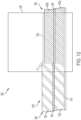
- FIGS. 11-12 depict the formation of the insulation component 400.
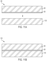
- FIGS. 11A-B depict the formation of an amalgam 1100 made of the core substrate 1120 and the insulation component 300. It is understood that features ending in like reference numerals as features discussed above are similar, except as noted below.
- the insulation component 300 may be provided in a cured form and coupled to the core substrate 1120 while the core substrate 1120 is uncured. Specifically, the facer layer 330 may be coupled to the core substrate 1120 to form an amalgam 1100, as shown in FIG. 11B . For example, the insulation component 300 may be pressed on top of the core substrate 1120. However, in other embodiments, the substrates may have any relative position when being pressed.
- the amalgam 1100 may be introduced into a curing system 600, as described above, to form the insulation component 300.
- the amalgam 1100 may be transported along the conveyor belt 610 into the curing oven 630 where the amalgam 1100 is heated to a curing temperature and the binding element starts to cure.
- the amalgam 1100 may be compressed prior to or during the curing stage.
- the amalgam 1100 may be compressed between the conveyor belt 610 and plate 620 while the amalgam 1100 is in the curing oven 630. This compresses the amalgam 1100 to have less thickness than when it first made contact with the plate 620.
- the core substrate 1120 is uncured while the insulation component 300 is cured, the core substrate 1120 is more malleable than the insulation component 300.
- compressing the amalgam 1100 compresses the less malleable insulation component 300 against the more malleable the core substrate 1120.
- Heating and compressing the amalgam 1100 may cure the binding element such that the amalgam 1100 cures into the insulation component 300 to have an increased density relative to the amalgam 1100. Specifically, this increases the density of the core substrate 1120 such that the core substrate 1120 is cured to be the core layer 420a.
- FIG. 13 depicts an exemplary flowchart 1300 for forming an insulation component. For example, this may include forming one of the insulation components 100, 200, 300, 400.
- a cured and uncured substrate are provided.
- the cured substrate may be one of the core substrates 520, 720, 920, 1120 and facer substrates 330, 730, 930.
- the uncured substrate may be one of the skin substrates 510, 710, facer substrates 330, 730, 930, or core substrate 1120.
- the first and second substrates are a fiberglass material.
- the cured and uncured substrates are coupled together with a binding element to form an amalgam.
- the cured and uncured substrates may be coupled together by being pressed together.
- the amalgam may be one of the amalgams 500, 700, 900, 1100.
- the binding element is a cohesive binder.
- the amalgam is cured to form the insulation component having a first layer with a first density and a second layer with a second density less than the first density.
- the first and second layers may comprise a similar material.
- the first density may provide the insulation component with enough rigidity to be self-supporting.
- the insulation component may include a fiber diameter less than 2 ⁇ m or a density of less than 1.5 pcf.
- the amalgams 500, 700, 900, 1100 may be cured in a curing system 600 to respectively form an insulation component 100, 200, 300, 400.
- the amalgams 500, 700, 900, 1100 may be heated and compressed in the curing oven such that the binding element is cured and the amalgams 500, 700, 900, 1100 is respectively cured into the insulation component 100, 200, 300, 400.
- the cured substrate is a first cured substrate and providing the cured and uncured substrates includes providing a second cured substrate
- curing the amalgam to form the insulation component includes compressing the first cured substrate, the second cured substrate, and the uncured substrate together to increase a density of the uncured substrate.
- the first cured substrate may be the core layer 320
- the second cured substrate may be the facer layer 330
- the uncured substrate may be the core substrate 1120.
- the insulation components may be used with other vehicles, including naval vessels (e.g., submarines, boats, or the like) or train cars (e.g., high-speed rail train cars or the like).
- naval vessels e.g., submarines, boats, or the like
- train cars e.g., high-speed rail train cars or the like.
Landscapes
- Engineering & Computer Science (AREA)
- Mechanical Engineering (AREA)
- Aviation & Aerospace Engineering (AREA)
- Laminated Bodies (AREA)
Abstract
Description
- Airplanes are an increasingly common method of transportation. As airplane technologies improve, airplanes can travel faster and farther than ever before. Moreover, improvements in airplane technology have made flights cheaper and more accessible. Further, airplanes are becoming safer, thus giving people a greater confidence in using airplanes. As such, airplanes have become an important aspect of nearly all modern-day society.
- One important design aspect of airplanes are the noise and temperature within the airplane. Airplanes generate tremendous amount of noise while flying given the amount of energy and propulsion required for flight as well as the surrounding air turbulence. Moreover, airplanes experience subzero temperatures at high altitudes. As such, the interiors of the airplanes may naturally be loud and cold.
- One way to mitigate the amount of noise and temperature bleeding into the interior of the airplane is through insulation. For example, insulation may be applied throughout the airplane fuselage to reduce how much noise leaks into the airplane. Moreover, insulation reduces heat transfer between the interior of the airplane and the sub-zero exterior temperatures. Insulation, therefore, serves as an important part of the airplane by reducing the interior noise levels of an airplane and making the temperature more comfortable for passengers.
- Accordingly, it would be beneficial for improved insulation designs, and methods of manufacturing thereof, that minimizes noise and temperature leakage within an airplane.
- One aspect of the disclosure provides an insulation component for use in an airplane, comprising a first fibrous layer having a first density and a second fibrous layer chemically bound to the first fibrous layer. The second fibrous layer has a second density less than the first density. The first and second fibrous layers comprise a similar material. The first density provides the insulation component with enough rigidity to be self-supporting. The fiber diameter of the fibers in the first and second fibrous layers is 20µm or less. The first and second fibrous layers may include a fiberglass material. The first and second fibrous layers may be cohesively bound together. The second density may provide the insulation component to have a rigidity of less than 1 inch of droop at a surface area of 22 inches by 8.5 inches. The insulation component may further comprise a third fibrous layer chemically bound to at least one of the first or second fibrous layers, the third fibrous layer having a third density different than the first and second densities. The third density may be greater than the first and second densities and the third fibrous layer may be positioned on top of the first fibrous layer and the first fibrous layer is positioned on top of the second fibrous layer. The third density may be substantially similar to the second density and the third fibrous layer may be positioned on top of the first fibrous layer and the first fibrous layer is positioned on top of the second fibrous layer. The first and second fibrous layers may provide the insulation component to have at least one of a flame propagation resistance value of less than 2 inches of material scorched and less than 3 seconds of after flame time from being tested via radiant panel and a water absorption of less than 20 g of water absorption on a sample of 10 inches by 10 inches by 4 inches or less that was submerged in water for 15 minutes and then allowed to drain for 1 minute on a sample of 10 inches by 10 inches by up to 4 inches in thickness.
- A further aspect of the disclosure provides an insulation component for use in an airplane, comprising a first fibrous layer having a first density and a second fibrous layer chemically bound to the first fibrous layer. The second fibrous layer has a second density different than the first density. The first and second fibrous layers comprise a similar material the first density provides the insulation component with enough rigidity to be self-supporting. The average density of the first and second fibrous layers is less than 1.5 pcf. The first and second fibrous layers may include a fiberglass material. The first and second fibrous layers may be cohesively bound together. The second density may provide the insulation component to have a rigidity of less than 1 inch of droop at a surface area of 22 inches by 8.5 inches. The first density may be greater than the second density and the insulation component may further comprise a third fibrous layer chemically bound to at least one of the first or second fibrous layers, the third fibrous layer having a third density different than the first and second densities. The third density may be greater than the first and second densities and the third fibrous layer may be positioned on top of the first fibrous layer and the first fibrous layer is positioned on top of the second fibrous layer. The third density may be substantially similar to the second density and the third fibrous layer may be positioned on top of the first fibrous layer and the first fibrous layer is positioned on top of the second fibrous layer. The first and second fibrous layers may provide the insulation component to have at least one of a flame propagation resistance value of less than 2 inches of material scorched and less than 3 seconds of after flame time from being tested via radiant panel and a water absorption of less than 20 g of water absorption on a sample of 10 inches by 10 inches by 4 inches or less that was submerged in water for 15 minutes.
- A further aspect of the disclosure provides for a method of manufacturing an insulation component for use in an airplane, comprising providing a cured substrate comprising fibers and an uncured substrate comprising fibers, coupling the cured and uncured substrates together with a binding element to form an amalgam, and curing the amalgam to form the insulation component having a first and second fibrous layer. The first and second fibrous layers comprise a similar material. The first density provides the insulation component with enough rigidity to be self-supporting. The insulation component includes at least one of a fiber diameter less than 20 µm or a density of less than 1.5 pcf. The first and second substrates may include a fiberglass material. The binding element may include a cohesive binder. Curing the amalgam to form the insulation component may include compressing the cured and uncured substrates together to increase a density of the uncured substrate. The cured substrate may be a first cured substrate, and providing the cured and uncured substrates may include providing a second cured substrate and curing the amalgam to form the insulation component may include compressing the first cure substrate, the second cured substrate, and the uncured substrate together to increase a density of the uncured substrate.
- A further understanding of the nature and advantages of various embodiments may be realized by reference to the following figures. In the appended figures, similar components or features may have the same reference label. Further, various components of the same type may be distinguished by following the reference label by a dash and a second label that distinguishes among the similar components. If only the first reference label is used in the specification, the description is applicable to any one of the similar components having the same first reference label irrespective of the second reference label.
-
FIG. 1 depicts an exemplary insulation component, according to some embodiments. -
FIG. 2 depicts an exemplary insulation component, according to some embodiments. -
FIG. 3 depicts an exemplary insulation component, according to some embodiments. -
FIG. 4 depicts an exemplary insulation component, according to some embodiments. -
FIGS. 5A-B depict the formation of an exemplary amalgam, according to some embodiments. -
FIG. 6 depicts the formation of the insulation component ofFIG. 1 with the amalgam ofFIGS. 5A-B . -
FIGS. 7A-B depict the formation of an exemplary amalgam, according to some embodiments. -
FIG. 8 depicts the formation of the insulation component ofFIG. 2 with the amalgam ofFIGS. 7A-B . -
FIGS. 9A-B depict the formation of an exemplary amalgam, according to some embodiments. -
FIG. 10 depicts the formation of the insulation component ofFIG. 3 with the amalgam ofFIGS. 9A-B . -
FIGS. 11A-B depict the formation of an exemplary amalgam, according to some embodiments. -
FIG. 12 depicts the formation of the insulation component ofFIG. 4 with the amalgam ofFIGS. 11A-B . -
FIG. 13 depicts an exemplary flow chart, according to some embodiments. - The present disclosure relates to an insulation component for use in vehicles. In particular, the present disclosure relates to a materially homogenous insulation component having layers with different densities. In some embodiments, the insulation component may be a fiberglass material.
- Aerospace insulation is used throughout an airplane to provide acoustic and thermal insulation. For example, insulation may be secured to the fuselage to minimize the amount of noise and heat transfer between the interior of the aircraft and the sub-zero conditions during flight. The fuselage may be formed by curved walls with supporting structures extending into the interior of the fuselage. The insulation may be secured to the fuselage between these supporting structures.
- In some examples, the insulation along the top and side portions of the fuselage (i.e., the crown and sidewall portions of the fuselage) may be installed on the fuselage between the support structures and against the walls of the fuselage. In this example, the insulation in these regions is supported by the walls of the fuselage itself and may not have the rigidity to support its shape and position without being laid against the fuselage wall (i.e., the insulation in these regions are not self-supporting).
- One example of insulation capable of being used in the top and side regions of the fuselage may include a fiberglass composite insulation. Such a fiberglass composite insulation may be constructed of multiple fiberglass insulation layers that are coupled together through mechanical fasteners (e.g., quilting, tags, or the like). The insulation layers may be chosen such that the combination of layers achieve certain acoustic and thermal insulation properties. This composite insulation may then be installed along the fuselage walls. However, such a mechanical coupling may allow one layer to move relative to the other, which increases the risk of damage to each layer. Further, such relative movement decreases the overall rigidity of the composite insulation, which may limit the usage of such composite insulation in certain locations that require greater rigidity. Additionally, such mechanical fasteners may fail or break over time, which results in the insulation layers coming apart. Accordingly, it would be beneficial for insulation having multiple layers to be joined together in a manner that increases the damage-tolerance and efficacy of the insulation.
- Other areas of the fuselage may require self-supporting insulation. For example, the bilge area, or an area of the airplane (usually in the lower part of the fuselage) where water collects due to the condensation formed in the fuselage (e.g., from water vapor in in the air condensing due to the cold temperatures outside of the fuselage), may require self-supporting insulation. Specifically, the insulation in the bilge area must be positioned between the supporting structures that extend from the wall of the fuselage but at a distance from the wall of the fuselage such that a space is defined between the insulation and the wall to allow for moisture to collect. As the insulation in the bilge areas are not directly supported by the walls of the fuselage, the insulation in this region must have enough rigidity to be self-supporting.
- One example of insulation capable of being used in the bilge area may include polyimide foam insulation. Polyimide foam insulation may have sufficient thermal/acoustic insulative qualities for use in an airplane while also being rigid enough that it may be self-supporting when installed in the bilge area. However, polyimide foam is expensive due to, in part, the extensive fabrication required to ensure that polyimide foam meets certain legal flame-resistance requirements (such as the Federal Aviation Administration mandated flame-resistance regulations). Accordingly, it would be beneficial for insulation to be made of a more cost-effective material while still having similar (or better) thermal/acoustic insulative, water-resistance, and flame-resistance qualities.
- The present disclosure relates generally to a semi-rigid insulation having multiple layers chemically bound together. In particular, the insulation of the present disclosure may be a materially homogeneous structure having layers of different density. The material may be a cost-effective material, such as fiberglass. One of the layers may be a high-density layer to provide sufficient rigidity and structure to the insulation. The rigidity and structure provided by this high-density layer may be sufficient to allow for the insulation to be self-supporting insulation while also being made of cost-effective material.
- The insulation may be rigid where the insulation can substantially maintain its shape when held aloft but cannot easily deform in shape without damaging the insulation. The insulation may be semi-rigid where the insulation can substantially maintain its shape when held aloft and can deform to a degree (e.g., the insulation may conform to a curved wall of an airplane) without damaging the insulation. The insulation may be flexible where the insulation cannot maintain its shape when held aloft and may be substantially deformable without structurally damaging the insulation.
- Exemplary insulation components are described below.
-
FIG. 1 depicts a cross-sectional view of anexemplary insulation component 100. Theinsulation component 100 includes askin layer 110 and asecond core layer 120. AlthoughFIG. 1 depicts twoinsulation layers installation component 100 is monolithic. Specifically, theinsulation component 100 may include no gaps between thelayers layers - Further, the
insulation component 100 may be materially homogenous in that thelayers insulation component 100 may be formed of substantially the same material when the materials of each of thelayers layers layers - In some embodiments, the
layers - Each of the insulation layers 110, 120 may have a different density that each provide a corresponding different rigidity. In particular, a
higher density layer insulation component 100 with a greater rigidity while alower density layer skin layer 110 may have a higher density relative to thecore layer 120 such that theskin layer 110 may be rigid or semi-rigid and thecore layer 120 may be flexible. However, in other embodiments, both of thelayers - The density of the
skin layer 110 ranging from 1.5-6 pounds per cubic foot (pcf), preferably from 2-5 pcf, 2.5-4.5 pcf, 3-4 pcf, or 3.5-4.5 pcf, be sufficiently high to provide theinsulation component 100 with enough rigidity that theinsulation component 100 is rigid or semi-rigid. In this manner, theinsulation component 100 may be installed on, for example, a bilge area of an airplane fuselage and be self-supporting (i.e., able to maintain its shape and position without any backing surface). For example, theinsulation component 100 may have also enough rigidity, as measured by droop level of about 1 inch or less with a sample size having a surface area of 22 inches by 8.5 inches and a thickness of between about 0.5-2 inches. For example, theinsulation component 100 may have a droop level at the areas described above between about 0.1-0.9 inches, 0.25-0.75 inches, or 0.4-0.6 inches. In particular, such a droop level may be achieved with theskin layer 110 having a thickness of about 0.25 inches. may have a thickness between about 0.13 inches to 0.25 inches. In some embodiments, to achieve such a droop level, theskin layer 120 may have a thickness between about 0.15 inches to 0.23 inches, between about 0.17 inches to 0.2 inches, or between about 0.18 inches to 0.19 inches. - In other embodiments, the
insulation component 100 may have a rigidity of less than 1 inch of droop at a surface area corresponding to a bilge area of an airplane as it may be desirable to prevent theinsulation component 100 from interacting with the fuselage walls where the water collects to prevent damage to theinsulation component 100. The space between theinsulation component 100 and the fuselage wall where the moisture collects may be just greater than 1 inch such theinsulation component 100 may be installed in those bilge areas to have enough rigidity (and be sufficiently self-supporting) that theinsulation component 100 would not droop to touch those fuselage walls. - In one embodiment, the
insulation component 100 may preferably have a density of 0.34 pfc. However, in other embodiments, theinsulation component 100 may have a variety of density ranges, formed from averaging the densities of thelayers insulation component 100 may reduce the total weight of theinsulation component 100 required to achieve the desired level of thermal/acoustic insulation for use in aircraft compared to other settings. The low-density values of theinsulation component 100 are an important consideration for insulation used in airplanes as optimizing airplane performance may include reducing the weight of the plane while maintaining a certain amount of structural integrity. For example, insulation used in heating, ventilation, and air condition (HVAC) settings in buildings consider density in terms of their ability to provide airflow resistance. Specifically, building or HVAC insulation may be provided at a certain minimum density so that the HVAC insulation are not torn off by the air flowing through it when installed in a building. As such, building or HVAC insulation would not include density values as low as those described above as doing so would render such insulation too weak to withstand the airflow passing through it. - On the other hand, insulation used in airplane (e.g., in the bilge area of an airplane) are not exposed to the airflow rates experienced by insulation used in building or HVAC. For example, airplane insulation may be provided away from any air flow and in a bag with flow-resistive qualities (e.g., polymeric bags) to further prevent air from flowing through the airplane insulation. Rather, insulation used in airplanes are directed more to decreasing the density of the insulation to decrease the total weight of the airplane while providing for certain acoustic and thermal insulative qualities. In this manner, the
insulation component 100 may be installed in an airplane to provide the acoustic and thermal insulation qualities described herein while having the rigidity to be self-supporting and the low-density values as described above. - The
skin layer 110 may have a density in ranges sufficiently high to provide theinsulation component 100 with enough rigidity that theinsulation component 100 is self-supporting, as discussed above. For example, theskin layer 110 may have a density in the range from about 1.5-6 pounds per cubic foot (pcf). In some cases, the density of the skin layer may be between about 2-5 pcf, 2.5-4.5 pcf, 3-4 pcf, or 3.5-4.5 pcf. Hence, the first fibrous layer having a first density ranging from 1.5-6 pounds per cubic foot (pcf), preferably from 2-5 pcf, 2.5-4.5 pcf, 3-4 pcf, or 3.5-4.5 pcf.. - The
core layer 120 may have a density in ranges to provide the acoustic/thermal insulative qualities as described below. For example,core layer 120 may have a density in the range from about 0.3-1.5 pcf. In some cases, the density of thecore layer 120 may be between about 0.32-1.3 pcf, 0.34-1.1 pcf, 0.5-1 pcf, 0.6-0.9 pcf, or 0.7-0.8 pcf. Thecore layer 120 may be more flexible than theskin layer 110 due to the lesser density of thecore layer 120. Hence, the second fibrous layer having a second density ranging from 0.3-1.5 pounds per cubic foot (pcf), preferably from 0.32-1.3 pcf, 0.34-1.1 pcf, 0.5-1 pcf, 0.6-0.9 pcf, or 0.7-0.8 pcf, with the proviso that the second density is less than the first density. - As noted above, the insulation layers 110, 120 may be a substantially similar material. This material may be a flame-resistant and water-repellant material such that the
insulation component 100 has a certain level of flame resistance (e.g., a flame propagation resistance) and water repellence, as described below. - For example, such material may have a flame resistance to satisfy the legal requirement as set forth under 14 C.F.R. § 25.856. In particular, the
insulation component 100 may have an after-flame time of less than 3 seconds and a flame propagation length of less than 2 inches from being tested via radiant panel with a sample size of 12 inches by 24 inches at a thickness between about 0.5-2 inches. This flame resistant quality may be beneficial when theinsulation component 100 is installed in airplanes to minimize flame propagation within aircraft or to increase fuselage burn-through time. The fire risk on an airplane can be disastrous as the means of putting out or controlling a fire are limited and, while the airplane is flying, there is no means to simply let the fire burn out. Further, certain government organizations (e.g., the Federal Aviation Administration) may enforce strict flammability requirements, as noted above, that, if not met, will prevent the use of insulation on certain airplanes (e.g., commercial airplanes). As such, the flame resistance of theinsulation component 100 may both reduce the risk of fire danger to the airplane, and allow it to be commercially sold and used. - Insulation used in other settings (e.g., building or HVAC settings, or the like) may not include similar flame resistance values as achieving such values may be unnecessary and prohibitively expensive. For example, building or HVAC insulation may follow the flame resistance requirements set forth under American Society for Testing and Materials (ASTM) E84. Such requirements may be less stringent than the test set forth for airplanes. On the other hand, the flame resistance values noted above for insulation used in airplanes may be achieved, in part, by, for example, a particular type of binding element, as discussed below. Such binding elements may be prohibitively expensive where such insulation does not require the particular level of flame resistance as insulation required in an airplane. As such, building or HVAC insulation would not include the flame resistance values as those described above.
- The insulation layers 110, 120 may be water repellant. For example, the
insulation component 100 may have water absorption levels of about 0.5 wt.% or less, based on the weight of theinsulation component 100. Theinsulation component 100 may be sufficiently water repellant to satisfy the requirements under the American Society for Testing and Materials (ASTM) C800 and C1511. Specifically, theinsulation component 100 may have a water absorption of less than 20 g of water absorption when submerged in water for 15 minutes and then allowed to drain for 1 minute on a sample of 10 inches by 10 inches by up to 4 inches in thickness being measured in accordance with the aforementioned testing. As noted above, achieving this level of water repellence may be prohibitively expensive (e.g., requiring a particular type of binding element and/or material) for insulation used outside of the airplane setting. For example, it would not be feasible or desirable for insulation used in the building or HVAC to have such high levels of water repellence due to the high cost and lack of need. - This water repellence may be beneficial for installing the
insulation component 100 in locations that may be in close proximity to liquids. For example, if theinsulation component 100 is installed at the bilge areas in an airplane do not have a certain level of water-resistance, the insulation component may absorb at least some water during the flight. This may lead to the insulation losing its thermal or acoustic insulative qualities. As such, the water-resistance of theinsulation component 100 may allow for theinsulation component 100 to be installed in locations proximate to water (e.g., the bilge areas in an airplane) while reducing the risk of damage and efficacy. - Examples of materials for the
insulation component 100 may include fiberglass based materials made of an inorganic material (e.g., woven or non-woven fibers) adhered together with a binding element, such as a thermosetting binder or resin. The fibers may include one or more fibers such as glass fibers, carbon fibers, among other kinds for fibers. In embodiments, the fibers may make up about 50 wt.% to about 99.5 wt.% of the fiberglass-containing products. Additional exemplary fiber weight ranges include about 90 wt.% to about 99 wt.%; and about 75 wt.% to about 95 wt%. - The
insulation component 100 may preferably be made of a fiberglass material. Fiberglass material may offer certain benefits over other materials. For example, fiberglass may include the flame resistance and water repellent values as noted above while also being more cost effective than other materials. For example, fiberglass material may provide better flame resistant and water repellant qualities as polyimide foam and may also be cheaper than the polyimide foam (e.g., by around 400%). While the fiberglass layers, separately, may normally be flexible, thefiberglass insulation component 100 may not be flexible due to rigidity provided by the high density of theskin layer 100. Specifically, the chemical bonding between thelayers skin layer 110 be transferred to the moreflexible core layer 120 in a more efficient manner than other means of connection, such as mechanical fasteners between layers (e.g., clips, tags, or the like). Unlike using mechanical fasteners to couple thelayers layers layers layers layers fiberglass insulation component 100 may be more cost-effective than other materials (e.g., polyimide foam) while also possessing similar flame-resistant and water-repellent qualities as those other materials and being more damage-resistant than using mechanical fasteners to form fiberglass insulation. - The acoustic insulation of the
insulation component 100 may be based on the fiber diameter of theinsulation component 100. Theinsulation component 100 may have a fiber diameter, formed from averaging the fiber diameters of thelayers insulation component 100 may have a fiber diameter between 0.1-20 µm, 0.2-18 µm, 0.5-15 µm, 0.75-10 µm, 1-8 µm, 1.5-5 µm, or 1.6-3 µm. Theinsulation component 100 may include such fine fiber diameters to improve the acoustic insulation provided by theinsulation components 100. This may be much finer than insulation used in other settings, such as building or HVAC settings, because acoustic insulation is an important consideration when used in airplanes due to the noise outside of the airplane. Further, the finer fiber diameter contributes to reducing the weight of theinsulation component 100, which reduces the weight of the overall airplane once installed. Moreover, manufacturing insulation with such fine fiber diameters is significantly more time-consuming and costly (e.g., greater than five times as expensive) than manufacturing insulation with larger fiber diameters. As such, building or HVAC insulation may not include such small fiber diameters as they are directed to a different use and the costs may be prohibitive. - Each of the
layers skin layer 110 may include a fiber diameter of between about 2-8 µm. For example, theskin layer 110 may include a fiber diameter between about 2.5-7.5 µm, 3-5 µm, 4-6 µm, or 3.5-5.5 µm. Thecore layer 120 may include a fiber diameter between about 0.5-20 µm. For example, thecore layer 120 may include a fiber diameter between about 0.9-16 µm, 1.1-12 µm, 1-10 µm, or 1.1-5 µm. These differences in fiber diameter may allow theinsulation component 100 to achieve the total fiber diameter, as discussed above, while minimizing the costs of manufacturing theinsulation component 100. Specifically, because the fiber diameter of theskin layer 110 is larger than thecore layer 120, theskin layer 110 may be cheaper to manufacture than thecore layer 110 in regard to fiber diameter. This may decrease the cost of manufacturing theinsulation component 100 while still manufacturing theinsulation component 100 to have the desired acoustic/thermal insulative qualities. - The use of fiberglass for
layers fiberglass skin layer 110 in combination with thefiberglass core layer 120 may provide a greater level of acoustic insulation than materials such as polyimide foam. In particular, thefiberglass skin layer 110 in combination with thecore layer 120 may provide a one and a half to three-times better acoustic impedance at frequency ranges greater than 500 Hz when tested via the testing procedure American Society for Testing and Materials (ASTM) E1050. For example, theinsulation component 100 may provide: at 800 Hz, an acoustic impedance greater than 0.8 compared to under 0.5 for polyimide foam; at 1200 Hz, acoustic impedance of around 0.9 compared to around 0.5 for polyimide foam; and at 3000 Hz, an acoustic impedance approaching 1 compared to 0.6 for polyimide foam. - The
layers - The binder may be a cohesive binder. Examples of a cohesive binder may include, for example, formaldehyde-containing binder compositions. Such compositions may include phenol-formaldehyde (PF) binder compositions, phenol-urea-formaldehyde (PUF) binder compositions, urea-formaldehyde (UF) binder compositions, and melamine-formaldehyde (MF) binder compositions, among other formaldehyde-containing binder compositions. In embodiments, PF binder compositions may include resole binder compositions where the amount of formaldehyde (by mole) exceeds the amount of phenol. Phenol-to-formaldehyde mole ratios in these resole binder compositions range from 1:1 to 1:5 (e.g., 1:1.2 to 1:4.5; 1:1.5 to 1:2.5; etc.). In further embodiments, the PF binder compositions are aqueous compositions characterized by a total solids concentration greater than or about 30 wt.%, greater than or about 40 wt.%, greater than or about 50 wt.%, greater than or about 60 wt.%, or more. Other example binders may be described in
U.S. Patent Application No. 17/318,430 entitled "Formaldehyde-Containing Products With Reduced Formaldehyde Emissions," which is incorporated by reference herein in their entirety. - In one example, the
layers insulation component 100 may have the water repellent values as noted above. Moreover, when set, the binder may contribute to theinsulation component 100 having flame propagation resistance values as described above. In particular, cohesive binders may be preferred where theinsulation component 100 is used in an airplane as adhesives are more flammable than the cohesive binder. Such binder properties may allow theinsulation component 100 to be installed in the bilge area of the airplane so as not to interfere with the collection of water and minimize the risk of fire. In other settings, such as in building or HVAC settings, insulation may not require as much water repellence and flame resistance as in airplanes. For example, manufacturing insulation to include such water repellent values (e.g., by including reactive silicone in the binder) may be prohibitively expensive where such values are not needed. As such, the building or HVAC insulation would not include binders that, when set, provide the water repellent and flame resistance levels as described above. - In other embodiments, the insulation component may have more layers than the
insulation component 100. For example,FIG. 2 depicts a cross-sectional view of anexample insulation component 200 including askin layer 210,core layer 220, and afacer layer 230. It is understood that features ending in like reference numerals as features discussed above are similar, except as noted below. Thefacer layer 230 may be any of the materials listed above and may be chemically bound to theskin layer 210 with a binding element as described above. In some embodiments, thelayers facer layer 230 may be thinner than theskin layer 220. For example, thefacer layer 230 may have a thickness of between about 0.013 inches to 0.042 inches. In some embodiments, to achieve the droop level as discussed above, thefacer layer 230 may have a thickness between about 0.02 inches to 0.04 inches, between about 0.025 inches to 00.35 inches, or about 0.03 inches. - The density of the
insulation component 200 may preferably be between about 0.34-0.6 pcf, formed from averaging the densities of thelayers insulation component 200 may have other density ranges, such as those described above for theinsulation component 100. In this manner, theinsulation component 200 may have a similar density as theinsulation component 100. Such similar densities may be achieved by decreasing at least one of the densities of the thickness or density of theskin layer 210 andcore layer 220 relative to, respectively, theskin layer 110 andcore layer 120. However, in other embodiments, thelayers insulation component 200 may have a total density different than theinsulation component 100. - The
facer layer 230 may be denser theskin layer 210 andcore layer 220. For example, thefacer layer 230 may have a density between about 6.5-8.5 pcf. However, thefacer layer 230 may have other ranges, such as between about 6.75-8.25 pcf, 7-8 pcf, between about 7.25-7.75 pcf. The relatively higher density of thefacer layer 230 compared to theskin layer 210 andcore layer 220 provides greater rigidity to theinsulation component 200 than just theskin layer 210 andcore layers 220 alone (e.g., compared to the insulation component 100). Theinsulation component 200 may have a greater rigidity than theinsulation component 100 due to having both theskin layer 210 andfacer layer 230 whereas theinsulation component 100 only includes theskin layer 110. - The
facer layer 230 may be made of a non-woven glass fiber material. This non-woven glassfiber facer layer 230 may alter the insulative qualities of theinsulation component 200 relative to theinsulation component 100 when compared to other materials, such as polyimide foam. For example, thefacer layer 230 may affect the acoustic insulation of theinsulation component 200 at different ranges compared to theinsulation component 100. Specifically, thefacer layer 230 may have a fiber diameter that contributes to theinsulation component 200 having an increased acoustic performance compared to polyimide foam at frequency ranges greater than 1000 Hz when tested via ASTM E1050. For example, thefacer layer 230 may include a fiber diameter between about 8-18 µm. In other embodiments, thefacer layer 230 may include a fiber diameter between about 10-16 µm, 12-14 µm, or 12.5-13.5 µm. Thefacer layer 230 may include a preferred fiber diameter of 13 µm. Theinsulation component 200 may have greater acoustic absorption than theinsulation component 100 as the addition of thefacer layer 230 may increase the total thickness of theinsulation component 200 to be greater than theinsulation component 100. - Although
FIG. 2 depicts thefacer layer 230 positioned on top of theskin layer 210 and theskin layer 210 positioned on top of thecore layer 220, in other embodiments, thelayers insulation component 200. - In other embodiments, the insulation component may have a different combination of layers than the
insulation components FIG. 3 depicts a cross-sectional view of anexample insulation component 300 includingcore layer 320 and afacer layer 330. It is understood that features ending in like reference numerals as features discussed above are similar, except as noted below. Thelayers layers - As discussed below, the
insulation component 300 may have different structural and insulative qualities than theinsulation components differing layers insulation components insulation component 300 may have less rigidity than theinsulation components facer layer 330 may not provide as much structural rigidity compared to the skin layers 120, 220 due to how thin thefacer layer 330 is. Moreover, theinsulation component 300 may have less acoustic absorption than theinsulation component insulation component 300 may have a lesser thickness thaninsulation component - In other embodiments, the insulation component may have a different combination of layers than the
insulation components FIG. 4 depicts a cross-sectional view of anexample insulation component 400 includingcore layers 420a,b and afacer layer 430. It is understood that features ending in like reference numerals as features discussed above are similar, except as noted below. Thelayers 420a,b, 430 may be any of the materials listed above and may be chemically bound together with a binding element as described above. In some embodiments, thelayers 420a,b, 430 may be substantially the same material. - The
insulation component 400 may have different structural and insulative qualities than theinsulation components differing layers 420a,b, 430 compared to the layers of theinsulation components insulation component 400 includes an increased overall thickness and density of theinsulation component 400 compared with theother insulation components layers 420a,b may have substantially similar densities. For example, the density of thelayers 420 a,b may be substantially the same when the densities are about 50 % to about 99.5 % the same. Alternatively, the density of thelayers 420 a,b may be substantially the same when the densities of thelayers 420 a,b are about 75 % to 99 % the same, about 80 % to 90 %, the same or about 90 % to about 99 % the same. However, in other embodiments, thelayers 420a,b may have different densities. For instance, where thecore layer 420a has a higher density than 420b, thecore layer 420a may provide some rigidity to theinsulation component 300. However, in other embodiments, thelayers 420a,b may have the same densities. - The
insulation component 400 may have a lesser rigidity than theinsulation components insulation component 300 due to having thesecond core layer 420a. Theinsulation component 400 may have a greater acoustic absorption than theinsulation components other insulation components - Exemplary manufacturing methods for the
insulation components -
FIGS. 5-12 depict an exemplary process for forming theinsulation components -
FIGS. 5-6 depict the formation of theinsulation component 100.FIGS. 5A-B depict the formation of anamalgam 500 made of theskin substrate 510 and thecore substrate 520.FIG. 5A depicts theskin substrate 510 and thecore substrate 520 being provided. Theskin substrate 510 may be provided on a surface (e.g., a conveyor belt) in an uncured form. Theskin substrate 510 may be a mixture of glass fibers mixed with an uncured binding element. For example, theskin substrate 510 may be formed by a deposition of fibers on the surface and then having an uncured binding element applied on the fibers (e.g., through one of spraying, curtain coating, spin coating, dip coating, among other contacting techniques). However, in other embodiments, theskin substrate 510 may be any of the materials listed above. - The
core substrate 520 may be provided in a cured form (e.g., similar tocore layers core substrate 520 may be made of a fiberglass material held together by a cured binding element. However, in other embodiments, thecore substrate 520 may be any of the materials listed above. Thecore substrate 520 may be coupled to theskin substrate 510 while theskin substrate 510 is uncured to form anamalgam 500, as shown inFIG. 5B . For example, thecore substrate 520 may be pressed on top of theskin substrate 510 to couple thesubstrates - Turning to
FIG. 6 , theamalgam 500 may be introduced into acuring system 600 to form theinsulation component 100. Thecuring system 600 may include aconveyor belt 610, aplate 620, and a curingoven 630. Specifically, theamalgam 500 may be transported along theconveyor belt 610 into the curingoven 630 where theamalgam 500 is heated to a curing temperature and the binding element starts to cure. The temperature of the curingoven 630 and the speed of theconveyor belt 610 may be adjusted to control the curing time and temperature of theamalgam 500. In some embodiments, temperature and speed may be set to completely cure the binding element such that theamalgam 500 cures into theinsulation component 100. However, in other embodiments, the temperature and speed may be set to partially cure theamalgam 500. - The
amalgam 500 may be compressed prior to or during the curing stage. For example, theamalgam 500 may be compressed between theconveyor belt 610 andplate 620 while theamalgam 500 is in the curingoven 630. This compresses theamalgam 500 to have less thickness than when it first made contact with theplate 620. As theskin substrate 510 is uncured while thecore substrate 520 is cured, theskin substrate 510 is more malleable than thecore substrate 520. As such, compressing theamalgam 500 compresses the lessmalleable core substrate 520 against the moremalleable skin substrate 510 to increase the density of theskin substrate 510. However, in other embodiments, there may be other means of compressing theamalgam 500 than as shown. - Heating and compressing the
amalgam 500 may cure the binding element such that theamalgam 500 cures into theinsulation component 100 to have an increased density relative to theamalgam 500. Specifically, this increases the density of theskin substrate 510 such that theskin substrate 510 is cured to be theskin layer 110, including having the increased density and rigidity of theskin layer 110. As thecore substrate 520 is already cured prior to the curing stage, the density of thecore substrate 520 is substantially the same as after this curing stage, when thecore substrate 520 becomes thecore layer 120. However, in other embodiments, thecore substrate 520 may also increase in density. - In other embodiments, the
skin substrate 510 may be cured and thecore substrate 520 may be uncured. In this embodiment, the position of theskin substrate 510 may be switched with thecore substrate 520 during the manufacturing process. -
FIGS. 7-8 depict the formation of theinsulation component 200.FIGS. 7A-B depict the formation of anamalgam 700 made of thecore substrate 720, theskin substrate 710, andfacer substrate 730. It is understood that features ending in like reference numerals as features discussed above are similar, except as noted below. Thecore substrate 720 and thefacer substrate 730 may be provided on a surface (e.g., a conveyor belt) in a cured form. Theskin substate 720 may be provided in an uncured form. However, in other embodiments, the facer substrate may be provided in an uncured form. In a yet further embodiment, the skin substrate may be provided in a cured form. - The
skin substrate 710 may be coupled to thefacer substrate 730 while theskin substrate 710 is uncured by pressing or the like to form theamalgam 700, shown inFIG. 7B . Thecore substrate 720 may be similarly coupled to theskin substrate 710 after theskin substrate 710 is coupled to thefacer substrate 730 or at the same time theskin substrate 710 is couped to thefacer substrate 730. - Turning to
FIG. 8 , theamalgam 700 may be introduced into thecuring system 600, as described above, to form theinsulation component 200. Theamalgam 700 may be transported along theconveyor belt 610 into the curingoven 630 where theamalgam 700 is heated to a curing temperature and the binding element starts to cure. - The
amalgam 700 may be compressed prior to or during the curing stage. For example, theamalgam 700 may be compressed between theconveyor belt 610 andplate 620 while theamalgam 700 is in the curingoven 630. This compresses theamalgam 700 to have less thickness than when it first made contact with theplate 620. As theskin substrate 710 is uncured while thecore substrate 720 andfacer substrate 730 is cured, theskin substrate 710 is more malleable than thecore substrate 720 andfacer substrate 730. As such, compressing theamalgam 700 compresses the moremalleable skin substrate 710 between the lessmalleable core substrate 720 andfacer substrate 730. In other embodiments, there may be other means of compressing theamalgam 700 than as shown. - Heating and compressing the
amalgam 700 may cure the binding element such that theamalgam 700 cures into theinsulation component 200 to have an increased density relative to theamalgam 700. Specifically, this increases the density of theskin substrate 710 such that theskin substrate 710 is cured to be theskin layer 210. As thecore substrate 720 andfacer substrate 730 are already cured prior to the curing stage, the density of thecore substrate 720 andfacer substrate 730 are substantially the same as after this curing stage, when thecore substrate 720 becomes thecore layer 220 and thefacer substrate 730 becomes thefacer layer 230. However, in other embodiments, at least one of the core and facer substrates may also increase in density when respectively becoming the core and facer layers. - Where the insulating
component 100 is coupled and compressed on thefacer substrate 730, only thefacer substrate 730 cures into thefacer layer 230. As the insulatingcomponent 100 is already cured prior to this curing stage, the density of the insulatingcomponent 100 is substantially the same as after this curing stage. However, in other embodiments, the insulatingcomponent 100 may also increase in density. -
FIGS. 9-10 depict the formation of theinsulation component 300.FIGS. 9A-B depict the formation of anamalgam 900 made of thefacer substrate 930 and the core substrate 910. It is understood that features ending in like reference numerals as features discussed above are similar, except as noted below. - The core substrate 910 may be provided in a cured form and coupled to the
facer substrate 930 while thefacer substrate 930 is uncured to form anamalgam 900, as shown inFIG. 9B . For example, the core substrate 910 may be pressed on top of thefacer substrate 930. However, in other embodiments, the facer substrate may be positioned on top of the core substrate when being pressed. - Turning to
FIG. 10 , theamalgam 900 may be introduced into acuring system 600, as described above, to form theinsulation component 300. Theamalgam 900 may be transported along theconveyor belt 610 into the curingoven 630 where theamalgam 900 is heated to a curing temperature and the binding element starts to cure. - The
amalgam 900 may be compressed prior to or during the curing stage. For example, theamalgam 900 may be compressed between theconveyor belt 610 andplate 620 while theamalgam 900 is in the curingoven 630. This compresses theamalgam 900 to have less thickness than when it first made contact with theplate 620. As thefacer substrate 730 is uncured while thecore substrate 920 is cured, thefacer substrate 930 is more malleable than thecore substrate 920. As such, compressing theamalgam 900 compresses the lessmalleable core substrate 920 against the moremalleable facer substrate 930. In other embodiments, there may be other means of compressing theamalgam 900 than as shown. However, as noted above, the facer substrate may be provided in a cured form. - Heating and compressing the
amalgam 900 may cure the binding element such that theamalgam 900 cures into theinsulation component 300 to have an increased density relative to theamalgam 900. Specifically, this increases the density of thefacer substrate 930 as thefacer substrate 930 is cured to be thefacer layer 330. Where the facer substrate is provided in a cured form, the facer substrate may include no change in density from before and after entering the curing oven. -
FIGS. 11-12 depict the formation of theinsulation component 400.FIGS. 11A-B depict the formation of anamalgam 1100 made of thecore substrate 1120 and theinsulation component 300. It is understood that features ending in like reference numerals as features discussed above are similar, except as noted below. - The
insulation component 300 may be provided in a cured form and coupled to thecore substrate 1120 while thecore substrate 1120 is uncured. Specifically, thefacer layer 330 may be coupled to thecore substrate 1120 to form anamalgam 1100, as shown inFIG. 11B . For example, theinsulation component 300 may be pressed on top of thecore substrate 1120. However, in other embodiments, the substrates may have any relative position when being pressed. - Turning to
FIG. 12 , theamalgam 1100 may be introduced into acuring system 600, as described above, to form theinsulation component 300. Theamalgam 1100 may be transported along theconveyor belt 610 into the curingoven 630 where theamalgam 1100 is heated to a curing temperature and the binding element starts to cure. - The
amalgam 1100 may be compressed prior to or during the curing stage. For example, theamalgam 1100 may be compressed between theconveyor belt 610 andplate 620 while theamalgam 1100 is in the curingoven 630. This compresses theamalgam 1100 to have less thickness than when it first made contact with theplate 620. As thecore substrate 1120 is uncured while theinsulation component 300 is cured, thecore substrate 1120 is more malleable than theinsulation component 300. As such, compressing theamalgam 1100 compresses the lessmalleable insulation component 300 against the more malleable thecore substrate 1120. In other embodiments, there may be other means of compressing theamalgam 1100 than as shown. - Heating and compressing the
amalgam 1100 may cure the binding element such that theamalgam 1100 cures into theinsulation component 300 to have an increased density relative to theamalgam 1100. Specifically, this increases the density of thecore substrate 1120 such that thecore substrate 1120 is cured to be thecore layer 420a. -
FIG. 13 depicts anexemplary flowchart 1300 for forming an insulation component. For example, this may include forming one of theinsulation components - At
step 1310, a cured and uncured substrate are provided. The cured substrate may be one of thecore substrates facer substrates skin substrates facer substrates core substrate 1120. In some embodiments, the first and second substrates are a fiberglass material. - At
step 1320, the cured and uncured substrates are coupled together with a binding element to form an amalgam. The cured and uncured substrates may be coupled together by being pressed together. The amalgam may be one of theamalgams - At
step 1330, the amalgam is cured to form the insulation component having a first layer with a first density and a second layer with a second density less than the first density. The first and second layers may comprise a similar material. The first density may provide the insulation component with enough rigidity to be self-supporting. The insulation component may include a fiber diameter less than 2 µm or a density of less than 1.5 pcf. Theamalgams curing system 600 to respectively form aninsulation component amalgams amalgams insulation component - In another example, where the cured substrate is a first cured substrate and providing the cured and uncured substrates includes providing a second cured substrate, curing the amalgam to form the insulation component includes compressing the first cured substrate, the second cured substrate, and the uncured substrate together to increase a density of the uncured substrate. In this example, with reference to
FIGS. 12-13 , the first cured substrate may be thecore layer 320, the second cured substrate may be thefacer layer 330, and the uncured substrate may be thecore substrate 1120. - Although the above disclosure has been directed towards the use of insulation components in airplanes. In other embodiments, the insulation components may be used with other vehicles, including naval vessels (e.g., submarines, boats, or the like) or train cars (e.g., high-speed rail train cars or the like).
- The specific details of particular embodiments may be combined in any suitable manner without departing from the spirit and scope of embodiments of the disclosure. However, other embodiments of the disclosure may be directed to specific embodiments relating to each individual aspect, or specific combinations of these individual aspects.
- The above description of example embodiments of the present disclosure has been presented for the purposes of illustration and description. It is not intended to be exhaustive or to limit the disclosure to the precise form described, and many modifications and variations are possible in light of the teaching above.
- A recitation of "a", "an" or "the" is intended to mean "one or more" unless specifically indicated to the contrary. The use of "or" is intended to mean an "inclusive or," and not an "exclusive or" unless specifically indicated to the contrary. Reference to a "first" component does not necessarily require that a second component be provided. Moreover, reference to a "first" or a "second" component does not limit the referenced component to a particular location unless expressly stated. The term "based on" is intended to mean "based at least in part on."
- The claims may be drafted to exclude any element which may be optional. As such, this statement is intended to serve as antecedent basis for use of such exclusive terminology as "solely", "only", and the like in connection with the recitation of claim elements, or the use of a "negative" limitation.
- All patents, patent applications, publications, and descriptions mentioned herein are incorporated by reference in their entirety for all purposes. None is admitted to be prior art. Where a conflict exists between the instant application and a reference provided herein, the instant application shall dominate.
Claims (18)
- An airplane insulation component, comprising:a first fibrous layer having a first density; anda second fibrous layer chemically bound to the first fibrous layer, the second fibrous layer having a second density less than the first density, wherein:the first and second fibrous layers comprise a similar material;the first density provides the insulation component with enough rigidity to be self-supporting; andan fiber diameter of the fibers in the first and second fibrous layers is 20µm or less, preferably between 0.1 -20 µm.
- The insulation component as claimed in claim 1, wherein the first and second fibrous layers include a fiberglass material.
- The insulation component as claimed in claim 1 or 2, wherein the first and second fibrous layers are cohesively bound together.
- The insulation component as claimed in one or more of claims 1 to 3, wherein the second density provides the insulation component to have a rigidity of less than 1 inch of droop at a surface area of 22 inches by 8.5 inches.
- The insulation component as claimed in one or more of claims 1 to 4, wherein the first density ranges from 1.5 to 6 pcf, preferably from 2 to 5 pcf, and the second density ranges from 0.3 to 1.5 pcf, preferably from 0.32 to 1.3 pcf.
- The insulation component as claimed in one or more of claims 1 to 5, further comprising a third fibrous layer chemically bound to at least one of the first or second fibrous layers, the third fibrous layer having a third density different than the first and second densities, preferably the third density is greater than the first and second densities; andthe third fibrous layer is positioned on top of the first fibrous layer and the first fibrous layer is positioned on top of the second fibrous layer or the third density is substantially similar to the second density; andthe third fibrous layer is positioned on top of the first fibrous layer and the first fibrous layer is positioned on top of the second fibrous layer.
- The insulation component as claimed in one or more of claims 1 to 6, wherein the first and second fibrous layers provide the insulation component to have at least one of:a flame propagation resistance value of less than 2 inches of material scorched and less than 3 seconds of after flame time from being tested via radiant panel; anda water absorption of less than 20 g of water absorption on a sample of 10 inches by 10 inches by 4 inches or less that was submerged in water for 15 minutes.
- An airplane insulation component, comprising:a first fibrous layer having a first density; anda second fibrous layer chemically bound to the first fibrous layer, the second fibrous layer having a second density different than the first density, wherein:the first and second fibrous layers comprise a similar material;the first density provides the insulation component with enough rigidity to be self-supporting; anda density of the first and second fibrous layers is less than 1.5 pcf.
- The insulation component as claimed in claim 8, wherein the first and second fibrous layers include a fiberglass material.
- The insulation component as claimed in claim 8 or 9, wherein the first and second fibrous layers are cohesively bound together.
- The insulation component as claimed in one or more of claims 8 to 10, wherein the second density provides the insulation component to have a rigidity of less than 1 inch of droop at a surface area of 22 inches by 8.5 inches.
- The insulation component as claimed in one or more of claims 8 to 11,wherein the first density is greater than the second density; andthe insulation component further comprises a third fibrous layer chemically bound to at least one of the first or second fibrous layers, the third fibrous layer having a third density different than the first and second densities, preferably the third density is greater than the first and second densities; andthe third fibrous layer is positioned on top of the first fibrous layer and the first fibrous layer is positioned on top of the second fibrous layer orthe third density is substantially similar to the second density; andthe third fibrous layer is positioned on top of the first fibrous layer and the first fibrous layer is positioned on top of the second fibrous layer.
- The insulation component as claimed in one or more of claims 8-12, wherein the first and second fibrous layers provide the insulation component to have at least one of:a flame propagation resistance value of less than 2 inches of material scorched and less than 3 seconds of after flame time from being tested via radiant panel; anda water absorption of less than 20 g of water absorption on a sample of 10 inches by 10 inches by 4 inches or less that was submerged in water for 15 minutes.
- A method of manufacturing an airplane insulation component, comprising:providing a cured substrate comprising fibers and an uncured substrate comprising fibers;coupling the cured and uncured substrates together with a binding element to form an amalgam; andcuring the amalgam to form the insulation component having a first and second fibrous layer, wherein:the first and second fibrous layers comprise a similar material;the first density provides the insulation component with enough rigidity to be self-supporting; andthe insulation component includes at least one of (i) a fiber diameter of 20µm or less, preferably between 0.1 - 20 µm or (ii) a density of less than 1.5 pcf.
- The method of claim 14, wherein the first and second substrates include fiberglass material.
- The method of claim 14 or 15, wherein the binding element includes a cohesive binder.
- The method of claim 14 or 15, wherein curing the amalgam to form the insulation component includes compressing the cured and uncured substrates together to increase a density of the uncured substrate.
- The method of claim 14, wherein:the cured substrate is a first cured substrate;providing the cured and uncured substrates includes providing a second cured substrate; andcuring the amalgam to form the insulation component includes compressing the first cure substrate, the second cured substrate, and the uncured substrate together to increase a density of the uncured substrate.
Applications Claiming Priority (1)
| Application Number | Priority Date | Filing Date | Title |
|---|---|---|---|
| US17/994,660 US12263665B2 (en) | 2022-11-28 | 2022-11-28 | Aerospace thermal acoustic fiberglass insulation useful in supporting applications |
Publications (1)
| Publication Number | Publication Date |
|---|---|
| EP4375060A1 true EP4375060A1 (en) | 2024-05-29 |
Family
ID=88923702
Family Applications (1)
| Application Number | Title | Priority Date | Filing Date |
|---|---|---|---|
| EP23211429.8A Pending EP4375060A1 (en) | 2022-11-28 | 2023-11-22 | Aerospace thermal acoustic fiberglass insulation useful in supporting applications |
Country Status (2)
| Country | Link |
|---|---|
| US (2) | US12263665B2 (en) |
| EP (1) | EP4375060A1 (en) |
Citations (3)
| Publication number | Priority date | Publication date | Assignee | Title |
|---|---|---|---|---|
| US3141811A (en) * | 1958-04-01 | 1964-07-21 | Johns Manville Fiber Glass Inc | Fibrous laminate and method of producing the same |
| CA690889A (en) * | 1964-07-21 | J. Hannes George | Fibrous laminate and method of producing same | |
| US20100064629A1 (en) * | 2008-09-15 | 2010-03-18 | Hogan Charles R | Wall panel system |
Family Cites Families (7)
| Publication number | Priority date | Publication date | Assignee | Title |
|---|---|---|---|---|
| US5824973A (en) | 1992-09-29 | 1998-10-20 | Johns Manville International, Inc. | Method of making sound absorbing laminates and laminates having maximized sound absorbing characteristics |
| US7377084B2 (en) | 2000-04-24 | 2008-05-27 | Hunter Douglas Inc. | Compressible structural panel |
| US6630222B1 (en) | 2000-06-16 | 2003-10-07 | Johns Manville International, Inc. | Acoustic media |
| US6607851B2 (en) * | 2001-10-26 | 2003-08-19 | The Boeing Company | Multi-layer ceramic fiber insulation tile |
| US7367527B2 (en) | 2005-08-23 | 2008-05-06 | Johns Manville | Reinforced insulation product and system suitable for use in an aircraft |
| US8534419B2 (en) | 2008-10-16 | 2013-09-17 | Zephyros, Inc. | Composite sound absorber |
| EP3246442B1 (en) | 2017-03-17 | 2019-11-13 | Carl Freudenberg KG | Sound absorbing textile composite |
-
2022
- 2022-11-28 US US17/994,660 patent/US12263665B2/en active Active
-
2023
- 2023-11-22 EP EP23211429.8A patent/EP4375060A1/en active Pending
-
2025
- 2025-02-21 US US19/059,498 patent/US20250187300A1/en active Pending
Patent Citations (3)
| Publication number | Priority date | Publication date | Assignee | Title |
|---|---|---|---|---|
| CA690889A (en) * | 1964-07-21 | J. Hannes George | Fibrous laminate and method of producing same | |
| US3141811A (en) * | 1958-04-01 | 1964-07-21 | Johns Manville Fiber Glass Inc | Fibrous laminate and method of producing the same |
| US20100064629A1 (en) * | 2008-09-15 | 2010-03-18 | Hogan Charles R | Wall panel system |
Also Published As
| Publication number | Publication date |
|---|---|
| US12263665B2 (en) | 2025-04-01 |
| US20240173938A1 (en) | 2024-05-30 |
| US20250187300A1 (en) | 2025-06-12 |
Similar Documents
| Publication | Publication Date | Title |
|---|---|---|
| EP1165367B1 (en) | Burn through resistant systems for transportation, especially aircraft | |
| CN102658687B (en) | For the mixed goods system of the ambient stable of aircraft exterior protection | |
| US9238505B2 (en) | Composite laminate for a thermal and acoustic insulation blanket | |
| US9032690B2 (en) | Insulation element for a flat roof or a flat inclined roof, roofing system for a flat roof or a flat inclined roof and method for producing an insulation element | |
| KR102422424B1 (en) | vibration damping system | |
| CN113650375B (en) | Impact-resistant and flame-retardant floor and preparation method thereof | |
| EP3439864B1 (en) | Fire retarded aramid fiber-based honeycomb | |
| KR20070114042A (en) | Surface Coated Fiber Reinforced Thermoplastic Sheet | |
| JP2019011039A (en) | Structural panel for exposed surface | |
| CN116100907B (en) | Preparation method of aircraft cargo compartment floor and aircraft cargo compartment floor | |
| US4880681A (en) | Low heat output composite | |
| US12263665B2 (en) | Aerospace thermal acoustic fiberglass insulation useful in supporting applications | |
| US11130560B2 (en) | Burnthrough resistant floor panels and method of manufacturing and installation | |
| US7740932B2 (en) | Hybrid fiberglass composite structures and methods of forming the same | |
| EP0662492A1 (en) | Fire-safe panels, fixtures and laminated honeycomb structures of fiber-reinforced ceramic material | |
| US20050287383A1 (en) | Fire and smoke resistant panels and laminates for vehicles and method of manufacture | |
| US5418050A (en) | Fire/heat barrier laminates | |
| EP1467861B1 (en) | Fire and smoke resistant panels and laminates for vehicles and method of manufacture | |
| CN210271764U (en) | A PET sound-absorbing cotton | |
| CN107215026A (en) | A kind of lightweight grafting high-strength composite material floor | |
| JPH10100299A (en) | Molded sound absorbing material and method of manufacturing the same | |
| US5593780A (en) | Impact resistant phenolics | |
| US8916082B2 (en) | Heat resistance using titanium dioxide nanofibers | |
| KR101894725B1 (en) | Heat-resistant Nonwoven Fabric Sheet | |
| CN118849567B (en) | Fireproof multilayer composite film, heat insulation felt and preparation method of heat insulation felt |
Legal Events
| Date | Code | Title | Description |
|---|---|---|---|
| PUAI | Public reference made under article 153(3) epc to a published international application that has entered the european phase |
Free format text: ORIGINAL CODE: 0009012 |
|
| STAA | Information on the status of an ep patent application or granted ep patent |
Free format text: STATUS: THE APPLICATION HAS BEEN PUBLISHED |
|
| AK | Designated contracting states |
Kind code of ref document: A1 Designated state(s): AL AT BE BG CH CY CZ DE DK EE ES FI FR GB GR HR HU IE IS IT LI LT LU LV MC ME MK MT NL NO PL PT RO RS SE SI SK SM TR |
|
| STAA | Information on the status of an ep patent application or granted ep patent |
Free format text: STATUS: REQUEST FOR EXAMINATION WAS MADE |
|
| 17P | Request for examination filed |
Effective date: 20241126 |
|
| RBV | Designated contracting states (corrected) |
Designated state(s): AL AT BE BG CH CY CZ DE DK EE ES FI FR GB GR HR HU IE IS IT LI LT LU LV MC ME MK MT NL NO PL PT RO RS SE SI SK SM TR |