EP4375012A1 - Top ring of polishing apparatus and polishing apparatus - Google Patents
Top ring of polishing apparatus and polishing apparatus Download PDFInfo
- Publication number
- EP4375012A1 EP4375012A1 EP22845765.1A EP22845765A EP4375012A1 EP 4375012 A1 EP4375012 A1 EP 4375012A1 EP 22845765 A EP22845765 A EP 22845765A EP 4375012 A1 EP4375012 A1 EP 4375012A1
- Authority
- EP
- European Patent Office
- Prior art keywords
- groove
- band
- top ring
- outer peripheral
- peripheral wall
- Prior art date
- Legal status (The legal status is an assumption and is not a legal conclusion. Google has not performed a legal analysis and makes no representation as to the accuracy of the status listed.)
- Pending
Links
Images




Classifications
-
- B—PERFORMING OPERATIONS; TRANSPORTING
- B24—GRINDING; POLISHING
- B24B—MACHINES, DEVICES, OR PROCESSES FOR GRINDING OR POLISHING; DRESSING OR CONDITIONING OF ABRADING SURFACES; FEEDING OF GRINDING, POLISHING, OR LAPPING AGENTS
- B24B37/00—Lapping machines or devices; Accessories
- B24B37/27—Work carriers
- B24B37/30—Work carriers for single side lapping of plane surfaces
- B24B37/32—Retaining rings
-
- B—PERFORMING OPERATIONS; TRANSPORTING
- B24—GRINDING; POLISHING
- B24B—MACHINES, DEVICES, OR PROCESSES FOR GRINDING OR POLISHING; DRESSING OR CONDITIONING OF ABRADING SURFACES; FEEDING OF GRINDING, POLISHING, OR LAPPING AGENTS
- B24B41/00—Component parts such as frames, beds, carriages, headstocks
- B24B41/06—Work supports, e.g. adjustable steadies
- B24B41/068—Table-like supports for panels, sheets or the like
Definitions
- the present invention relates to a top ring of a polishing apparatus and a polishing apparatus.
- This application claims priority from Japanese Patent Application No. 2021-118470 filed on July 19, 2021 .
- the entire disclosure including the description, the claims, the drawings, and the abstract in Japanese Patent Application No. 2021-118470 is herein incorporated by reference.
- a polishing apparatus including a top ring that holds a substrate and a polishing table that holds a polishing pad for polishing this substrate (for example, see PTL 1).
- the top ring of such a polishing apparatus includes a top ring main body having a substrate support surface that supports an upper surface of the substrate, a retainer member disposed so as to surround an outer periphery of the substrate support surface to hold an outer edge of the substrate, a pressing mechanism disposed above the retainer member and configured to press the retainer member downward, and a band disposed extending from an outer peripheral wall of the retainer member to an outer peripheral wall of the pressing mechanism.
- the top ring of the conventional polishing apparatus as described above had a risk of disengagement of the band from the retainer member or the pressing mechanism during the use of the top ring.
- the present invention has been made in view of the above-described circumstances, and one of the objects of the present invention is to provide a technique that allows suppressing disengagement of a band from a retainer member or a pressing mechanism during the use of a top ring.
- a top ring of a polishing apparatus includes a top ring main body, a retainer member, a pressing mechanism, and a band.
- the top ring main body has a substrate support surface supporting an upper surface of a substrate.
- the retainer member is disposed so as to surround an outer periphery of the substrate support surface to hold an outer edge of the substrate.
- the pressing mechanism is disposed above the retainer member and configured to press the retainer member downward.
- the band is disposed extending from an outer peripheral wall of the retainer member to an outer peripheral wall of the pressing mechanism, the band having at least one fitting portion.
- At least one of the outer peripheral wall of the retainer member and the outer peripheral wall of the pressing mechanism is provided with a groove in which the fitting portion of the band is fitted.
- the groove is a dovetail groove configured to have a groove opening, a groove bottom opposed to the groove opening, a first groove side wall connecting the groove opening to the groove bottom, and a second groove side wall connecting the groove opening to the groove bottom and opposed to the first groove side wall, in cross-sectional view, and the dovetail groove is configured such that an interval between the first groove side wall and the second groove side wall widens as the interval approaches the groove bottom.
- the fitting portion is configured to be in contact with the first groove side wall and the second groove side wall in a state where the fitting portion of the band is fitted in the dovetail groove.
- the groove in which the fitting portion of the band is fitted is the dovetail groove as described above, a degree of fitting between the fitting portion of the band and the groove can be strengthened in comparison to a case where the groove in which the fitting portion of the band is fitted is not the dovetail groove (for example, a case where an interval between the pair of groove side walls is a groove in a cross-sectionally constant rectangular shape).
- This allows suppressing disengagement of the fitting portion of the band from the groove during the use of the top ring.
- disengagement of the band from the retainer member or the pressing mechanism during the use of the top ring is suppressible.
- the fitting portion of the band may have a first projecting portion in contact with the first groove side wall and a second projecting portion in contact with the second groove side wall.
- a V-shaped groove in a cross-sectionally V shape may be provided between the first projecting portion and the second projecting portion.
- a part of the band may be provided with an expansion and contraction portion expandable and contractable in a vertical direction.
- the groove may be provided only on any one of the outer peripheral wall of the retainer member and the outer peripheral wall of the pressing mechanism.
- the groove may be provided on both the outer peripheral wall of the retainer member and the outer peripheral wall of the pressing mechanism.
- the groove may be provided only on the outer peripheral wall of the retainer member among the outer peripheral wall of the retainer member and the outer peripheral wall of the pressing mechanism.
- the top ring main body may have an upper side member disposed so as to cover an upper portion of the pressing mechanism.
- One end portion of both end portions of the band may be sandwiched between the upper side member and the pressing mechanism.
- the fitting portion of the band may be disposed on another end portion of the band.
- the groove opening may be provided with a depressed portion for a processing tool for processing the groove to pass through when the processing tool is inserted from the groove opening into the groove.
- the processing tool is easily insertable into the groove from the groove opening where the depressed portion is provided, the groove is easily processable.
- the substrate may be a polygonal substrate.
- a top ring of a polishing apparatus includes a top ring main body, a retainer member, a pressing mechanism, and a band.
- the top ring main body has a substrate support surface supporting an upper surface of a substrate.
- the retainer member is disposed so as to surround an outer periphery of the substrate support surface to hold an outer edge of the substrate.
- the pressing mechanism is disposed above the retainer member and configured to press the retainer member downward.
- the band is disposed extending from an outer peripheral wall of the retainer member to an outer peripheral wall of the pressing mechanism, the band having a fitting portion.
- the outer peripheral wall of the retainer member is provided with a groove in which the fitting portion of the band is fitted.
- the top ring main body has an upper side member disposed so as to cover an upper portion of the pressing mechanism. One end portion of both end portions of the band is sandwiched between the upper side member and the pressing mechanism. The fitting portion of the band is disposed on another end portion of the band.
- a polishing apparatus includes the top ring according to any one aspect of the above-described aspects 1 to 9 and a polishing table configured to hold a polishing pad for polishing the substrate held by the top ring.
- Fig. 1A is a schematic diagram illustrating a main configuration of a polishing apparatus 100 according to the embodiment.
- Fig. 1B is a schematic plan view (top view) of a polishing apparatus main body 101.
- the polishing apparatus 100 according to the embodiment is a polishing apparatus that can perform chemical mechanical polishing (CMP).
- CMP chemical mechanical polishing
- the polishing apparatus 100 exemplified in Fig. 1A includes the polishing apparatus main body 101 and a control device 120.
- the polishing apparatus main body 101 mainly includes a polishing table 102, a top ring 10, and a dresser 104.
- the polishing table 102 is configured to hold a polishing pad Pd and to rotate.
- the polishing table 102 according to the embodiment is configured of a disc-shaped member, and the polishing pad Pd is attached to an upper surface of the disc-shaped member.
- An upper surface (a front surface) of the polishing pad Pd corresponds to a polishing surface.
- the polishing table 102 is connected to a table rotation shaft 103.
- This table rotation shaft 103 is rotatably driven by a driving mechanism (for example, a rotation motor), and thus, the polishing table 102 rotates.
- a substrate Wf described later is pressed against the polishing pad Pd. This polishes the substrate Wf.
- the rotation operation of the polishing table 102 is controlled by the control device 120. Note that "R1" illustrated in Fig. 1B is one example of rotation directions of the polishing table 102.
- the polishing pad Pd is not particularly limited to a specific type, and various kinds of polishing pads, such as a polishing pad of a hard foam type, a polishing pad of a nonwoven fabric type, and a polishing pad of a suede type, can be employed.
- the substrate Wf as one example of the substrate Wf, a polygonal substrate with corner portions is employed.
- the number of the corner portions of this polygonal substrate is not particularly limited as long as it is three or more, and is four as one example in the embodiment. That is, the substrate Wf according to the embodiment is a quadrilateral substrate.
- the shape of the substrate Wf is not limited to such a polygon, and may, for example, be a circular shape (including an ellipse) without a corner portion.
- the top ring 10 is a member for holding the substrate Wf.
- the top ring 10 is configured to rotate while pressing a lower surface (that is, a surface to be polished) of the substrate Wf against the polishing pad Pd.
- the top ring 10 is connected to a ring rotation shaft 105.
- This ring rotation shaft 105 is rotatably driven by a driving mechanism (for example, a rotation motor), and thus, the top ring 10 rotates.
- a driving mechanism for example, a rotation motor
- the top ring 10 is configured to swing with respect to the polishing pad Pd.
- the ring rotation shaft 105 of the top ring 10 is connected to a substrate swing shaft 107 via a substrate swing arm 106.
- the substrate swing shaft 107 is swingably driven by a driving mechanism, thus, the substrate swing arm 106 swings in an arc about the substrate swing shaft 107 (that is, turns clockwise and counterclockwise), and as a result, the top ring 10 also swings in a similar way.
- the rotation operation and the swing operation of the top ring 10 are controlled by the control device 120.
- "SW1" illustrated in Fig. 1B is one example of swinging directions of the top ring 10.
- the dresser 104 is a member for dressing the polishing surface of the polishing pad Pd.
- the dresser 104 has a lower surface on which abrasive grains (for example, diamonds) are disposed.
- the dresser 104 is connected to a dresser rotation shaft 108.
- This dresser rotation shaft 108 is rotatably driven by a driving mechanism (for example, a rotation motor), and thus, the dresser 104 rotates.
- a driving mechanism for example, a rotation motor
- the dresser 104 is configured to swing with respect to the polishing pad Pd.
- the dresser rotation shaft 108 of the dresser 104 is connected to a dresser swing shaft 110 via a dresser swing arm 109.
- the dresser swing shaft 110 is swingably driven by a driving mechanism (for example, a swing motor), thus, the dresser swing arm 109 swings about the dresser swing shaft 110, and as a result, the dresser 104 also swings in a similar way.
- the rotation operation and the swing operation of this dresser 104 is controlled by the control device 120.
- "SW2" illustrated in Fig. 1B is one example of swinging directions of the dresser 104.
- the polishing apparatus 100 includes a slurry supply mechanism (not illustrated) for supplying slurry (polishing slurry) to the polishing surface of the polishing pad Pd.
- a solution containing abrasive grains of, for example, silicon oxide, aluminum oxide, and cerium oxide can be employed. It is only necessary that the specific type of this slurry is appropriately set according to the type of the substrate Wf. Note that the slurry may be supplied from an upper side of the polishing pad Pd, may be supplied from a lower side, or may be supplied from both the upper side and the lower side.
- the polishing apparatus 100 polishes the substrate Wf with each of the polishing table 102 and the top ring 10 rotating in the presence of the slurry.
- the control device 120 integrally controls the operation of the polishing apparatus 100.
- the control device 120 includes a microcomputer.
- This microcomputer includes a central processing unit (CPU) 121 as a processor, a storage device 122 as a non-transitory storage medium, and the like.
- the CPU 121 as the processor operates based on a command of a program stored in the storage device 122 to control the operation of the polishing apparatus 100.
- Fig. 2 is a schematic perspective view of the top ring 10.
- the top ring 10 according to the embodiment has a rectangular parallelepiped shape as one example.
- the top ring 10 has an outer peripheral wall 11 having a plurality of corner portions 12 and connection walls 13 connecting the neighboring corner portions 12.
- the number of the corner portions 12 is four.
- the number of the corner portions 12, however, is not limited to four, and may be three or may be five or more.
- the top ring 10 may have an external shape without the corner portions 12 (for example, a circular shape).
- the corner portion 12 may be rounded (in this case, the corner portion 12 is rounded).
- the connection wall 13 according to the embodiment is configured of a flat surface as one example.
- the outer peripheral wall 11 of the top ring 10 includes an outer peripheral wall of a retainer member 30 and an outer peripheral wall of a pressing mechanism 40, which will be described later, of the top ring 10.
- Fig. 3 is a schematic cross-sectional view of the top ring 10, and specifically, schematically illustrates a cross section taken along the line A1-A1 in Fig. 2 .
- Fig. 4 is a schematic enlarged cross-sectional view of the part B1 in Fig. 3 .
- the top ring 10 according to the embodiment includes a top ring main body 20, the retainer member 30, the pressing mechanism 40, a guide mechanism 50, a sealing member 60a, a sealing member 60b, and a band 70.
- the top ring main body 20 includes a lower side member 21, an intermediate member 22 disposed above the lower side member 21, an upper side member 23 disposed above the intermediate member 22, and an elastic film 24 disposed below the lower side member 21.
- This elastic film 24 has a lower surface corresponding to a "substrate support surface 24a" that supports an upper surface of the substrate Wf.
- the upper side member 23, the intermediate member 22, and the lower side member 21 are fastened to one other with a bolt (not illustrated).
- the elastic film 24 according to the embodiment is configured to expand like an airbag with the introduction of a gas.
- the top ring main body 20 having such an elastic film 24 allows pressing the substrate Wf against the polishing pad Pd with a uniform pressure while polishing the substrate Wf. Note that the configuration of this top ring main body 20 is not described in detail any further as it is similar to that of the top ring main body of the known polishing apparatus as described in PTL 1.
- the retainer member 30 is disposed to surround an outer periphery of the substrate support surface 24a.
- the retainer member 30 is configured to hold an outer edge of the substrate Wf.
- the retainer member 30 according to the embodiment includes a first member 31, a second member 32 disposed above the first member 31, and a third member 33 disposed above the second member 32 as one example.
- the outer edge of the substrate Wf is held by an inner peripheral wall of the first member 31.
- the pressing mechanism 40 is disposed above the retainer member 30.
- the pressing mechanism 40 is a mechanism for pressing the retainer member 30 downward.
- the pressing mechanism 40 is not particularly limited to a specific configuration as long as it has such a function, and the pressing mechanism 40 according to the embodiment includes a cylinder 41 and a piston 42 as one example.
- the cylinder 41 is disposed so as to surround an outer periphery of the intermediate member 22 of the top ring main body 20.
- the piston 42 projects downward from the cylinder 41.
- the piston 42 is displaced in a vertical direction with respect to the cylinder 41.
- the piston 42 has a lower end abutting on an upper surface of the third member 33 of the retainer member 30.
- the piston 42 is displaced downward, and thus, the retainer member 30 can be pressed downward.
- the lower end of the piston 42 may be connected to the third member 33 of the retainer member 30 to have a configuration in which the retainer member 30 can be driven in the vertical direction in association with the vertical displacement of the piston 42.
- the guide mechanism 50 is a mechanism for guiding the vertical displacement of the retainer member 30.
- the guide mechanism 50 is not particularly limited to a specific configuration as long as it has such a function, and the guide mechanism 50 according to the embodiment includes a guide roller 51, a guide pad 52, and a roller supporting member 53 as one example.
- the guide roller 51 is rotatably supported by the roller supporting member 53.
- the roller supporting member 53 is connected to the lower side member 21 via a bolt 14.
- the guide pad 52 is disposed on an inner peripheral surface of the third member 33 of the retainer member 30.
- the guide pad 52 is guided in the vertical direction by the guide roller 51 during the displacement of the retainer member 30. This guides the displacement of the retainer member 30. Note that the configuration of this guide mechanism 50 is not described in detail any further as it is similar to that of a guide mechanism of the known polishing apparatus as described in PTL 1.
- the sealing member 60a is sandwiched between the second member 32 and the third member 33 of the retainer member 30 and is also sandwiched between the roller supporting member 53 and the lower side member 21 of the top ring main body 20. Note that the sealing member 60a may further be secured to the second member 32 and/or the third member 33 with a bolt (not illustrated). The sealing member 60a is disposed in order to inhibit the entry of the slurry into the guide roller 51 during the polishing of the substrate Wf.
- the top ring main body 20 is internally provided with a space 25.
- the upper side member 23 of the top ring main body 20 is disposed so as to cover an upper portion of the cylinder 41 of the pressing mechanism 40.
- the sealing member 60b is sandwiched between the upper side member 23 and the cylinder 41. Note that the sealing member 60b may further be secured to the cylinder 41 and/or the upper side member 23 with a bolt (not illustrated).
- the sealing member 60b is disposed in order to inhibit the entry of the slurry into the space 25 inside the top ring main body 20 from a clearance between the upper side member 23 and the cylinder 41.
- the configurations of the sealing member 60a and the sealing member 60b are not described in detail any further as they are similar to that of a sealing member of the known polishing apparatus as described in PTL 1.
- FIG. 5A is schematic enlarged cross-sectional views of the part B2 and the part B3 in Fig. 4 .
- Fig. 5B is an exploded view schematically illustrating a state where the configuration of the part B2 in Fig. 4 is disassembled.
- the band 70 is disposed extending from the outer peripheral wall 11 of the retainer member 30 to the outer peripheral wall 11 of the pressing mechanism 40.
- the band 70 according to the embodiment is disposed extending from the outer peripheral wall 11 of the third member 33 of the retainer member 30 to the outer peripheral wall 11 of the cylinder 41 of the pressing mechanism 40.
- the band 70 is disposed extending entirely in a circumferential direction of the outer peripheral walls 11.
- the band 70 is disposed so as to cover a clearance 26 between the retainer member 30 and the pressing mechanism 40.
- the band 70 is mainly disposed in order to inhibit the entry of the slurry from the clearance 26 to the space 25 during the polishing of the substrate Wf.
- the band 70 according to the embodiment has an external shape of a polygonal ring as a whole.
- the band 70 has at least one "fitting portion" for being fitted in a groove 15 described later.
- the band 70 according to the embodiment has a fitting portion 71a and a fitting portion 71b positioned above the fitting portion 71a.
- the fitting portion 71b according to the embodiment is disposed at one end portion (specifically, an upper end portion) of both end portions of the band 70.
- the fitting portion 71a according to the embodiment is disposed at the other end portion (specifically, a lower end portion) of both the end portions of the band 70.
- At least the fitting portion of the band 70 according to the embodiment is configured of an elastic member, such as rubber.
- the band 70 according to the embodiment has not only the fitting portion but also portions other than the fitting portion that are configured of the elastic member. That is, the band 70 according to the embodiment is entirely configured of the elastic member.
- the groove 15 may be provided only on the outer peripheral wall 11 of the retainer member 30, may be provided only on the outer peripheral wall 11 of the pressing mechanism 40, or may be provided on both the outer peripheral wall 11 of the retainer member 30 and the outer peripheral wall 11 of the pressing mechanism 40.
- the number of the fitting portions of the band 70 corresponds to the number of the grooves 15.
- the number of the fitting portions of the band 70 according to the embodiment is two, and therefore, the grooves 15 are also provided at two places.
- the grooves 15 according to the embodiment are provided on both the outer peripheral wall 11 of the retainer member 30 and the outer peripheral wall 11 of the pressing mechanism 40.
- the fitting portion 71b of the band 70 is fitted in the groove 15 provided on the outer peripheral wall 11 of the pressing mechanism 40 (specifically, the cylinder 41), and the fitting portion 71a of the band 70 is fitted in the groove 15 provided on the outer peripheral wall 11 of the retainer member 30 (specifically, the third member 33).
- the configuration of the groove 15 provided on the outer peripheral wall 11 of the retainer member 30 is similar to the configuration of the groove 15 provided on the outer peripheral wall 11 of the pressing mechanism 40. Therefore, the groove 15 will be described in detail with the groove 15 provided on the outer peripheral wall 11 of the pressing mechanism 40 as a specific example.
- the groove 15 has a groove opening 15a, a groove bottom 15b opposed to the groove opening 15a, a pair of groove side walls (a first groove side wall 15c and a second groove side wall 15d) connecting the groove opening 15a to the groove bottom 15b.
- the first groove side wall 15c and the second groove side wall 15d are opposed to one another.
- the first groove side wall 15c and the second groove side wall 15d are configured such that an interval d1 (that is, a "groove width") between the first groove side wall 15c and the second groove side wall 15d widens as the interval d1 approaches the groove bottom 15b. That is, the groove 15 according to the embodiment is a "dovetail groove.”
- this fitting portion is configured to be in contact with the first groove side wall 15c and the second groove side wall 15d.
- the groove 15 in which the fitting portion of the band 70 is fitted is the dovetail groove
- a degree of fitting between the fitting portion of the band 70 and the groove 15 can be strengthened in comparison to a case where the groove in which the fitting portion of the band is fitted is not the dovetail groove (for example, a case where the interval between the pair of groove side walls is a groove in a cross-sectionally constant rectangular shape).
- This allows suppressing disengagement of the fitting portion of the band 70 from the groove 15 during the use of the top ring 10.
- disengagement of the band 70 from the retainer member 30 or the pressing mechanism 40 during the use of the top ring 10 is suppressible.
- the dovetail groove is provided in both the retainer member 30 and the pressing mechanism 40 as in the embodiment, it is possible to suppress the disengagement of the band 70 from the retainer member 30 and the pressing mechanism 40 during the use of the top ring 10.
- each of the fitting portion 71b and the fitting portion 71a has a first projecting portion 72 (in other words, a first "bump") in contact with the first groove side wall 15c and a second projecting portion 73 (in other words, a second "bump") in contact with the second groove side wall 15d.
- a V-shaped groove 74 having a V-shaped cross section is provided.
- this V-shaped groove 74 is configured such that an interval d2 (that is, a "groove width") of the V-shaped groove 74 widens toward distal ends of the first projecting portion 72 and the second projecting portion 73 in cross-sectional view.
- a width d3 of the first projecting portion 72 and the second projecting portion 73 according to the embodiment is preliminarily set such that the first projecting portion 72 is in contact with the first groove side wall 15c and the second projecting portion 73 is in contact with the second groove side wall 15d. Furthermore, the maximum value of the width d3 of the first projecting portion 72 and the second projecting portion 73 according to the embodiment is a value larger than the minimum value of the interval d1 between the first groove side wall 15c and the second groove side wall 15d (that is, the size of the groove opening 15a).
- a part of the band 70 according to the embodiment is provided with an expansion and contraction portion 75 expandable and contractable in the vertical direction.
- This configuration allows this expansion and contraction portion 75 to expand and contract in the vertical direction when the retainer member 30 is displaced in the vertical direction, thereby allowing effective suppression of the disengagement of the fitting portion of the band 70 from the groove 15.
- the dovetail groove is provided over the whole circumference of the outer peripheral wall 11 in the circumferential direction (that is, the dovetail groove is provided on the connection walls 13 and the corner portions 12), the configuration is not limited to this.
- the dovetail groove may be provided only on the connection walls 13, without being provided on the corner portions 12, of the outer peripheral wall 11.
- the corner portion 12 may be provided with, for example, a groove in a cross-sectionally rectangular shape (a groove having a constant interval between the first groove side wall 15c and the second groove side wall 15d from the groove opening 15a to the groove bottom 15b) instead of the dovetail groove.
- the pressing mechanism 40 When the pressing mechanism 40 is compared with the retainer member 30, the pressing mechanism 40 tends to allow a liquid, such as a cleaning liquid (for example, a cleaning liquid for cleaning the top ring 10) and slurry for polishing, to easily enter from a part of the dovetail groove. Therefore, when only any one dovetail groove of the dovetail groove of the pressing mechanism 40 and the dovetail groove of the retainer member 30 is provided over the whole circumference of the outer peripheral wall 11, the configuration may have, for example, the dovetail groove of the pressing mechanism 40 provided over the whole circumference of the outer peripheral wall 11 and the dovetail groove of the retainer member 30 not provided over the whole circumference of the outer peripheral wall 11. In this case, the retainer member 30 may be provided with a groove in a cross-sectionally rectangular shape.
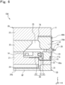
- Fig. 6 is an enlarged cross-sectional view schematically illustrating an enlarged part of a top ring 10A of a polishing apparatus 100 according to a modification 1 of the embodiment.
- Fig. 6 schematically illustrates an enlarged part which is the same part (the part B1) as in Fig. 4 described above.
- the top ring 10A according to the modification is different from the top ring 10 illustrated in Fig. 4 described above in that it includes a pressing mechanism 40A instead of the pressing mechanism 40 and that it includes a band 70A instead of the band 70.
- the pressing mechanism 40A according to the modification is different from the pressing mechanism 40 exemplified in Fig. 4 in that it does not have a groove 15.
- the band 70A according to the modification is different from the band 70 exemplified in Fig. 4 in that one end portion 76 of both end portions of the band 70A is sandwiched between an upper side member 23 and the pressing mechanism 40A.
- the band 70A has a region from the one end portion 76 to the other end portion of the band 70A by a predetermined distance sandwiched between the upper side member 23 and an upper surface of a cylinder 41 of the pressing mechanism 40A.
- the one end portion 76 of the band 70A according to the modification is secured to the upper surface of the cylinder 41.
- the band 70A may further be secured to the upper surface of the cylinder 41 with a bolt.
- the other end part of the band 70A according to the modification is configured of a fitting portion 71a described above, and this fitting portion 71a is fitted in a groove 15 (the dovetail groove) of a retainer member 30.
- the fitting portion 71a of the band 70A is fitted in the groove 15 (the dovetail groove), and thus, disengagement of the fitting portion 71a from the groove 15 is suppressible.
- disengagement of the band 70A from the retainer member 30 during the use of the top ring 10A is suppressible.
- the one end portion 76 of the band 70A is sandwiched between the upper side member 23 and the pressing mechanism 40A, and thus, disengagement of the one end portion 76 is also suppressible. As a result, disengagement of the band 70A from the pressing mechanism 40A during the use of the top ring 10A is suppressible.
- disengaging the fitting portion 71a of the band 70A from the groove 15 during the maintenance of the top ring 10A allows, for example, easily dividing the retainer member 30 from the top ring 10A.
- the retainer member 30 and members disposed next to the retainer member 30 specifically, a lower side member 21 and a guide mechanism 50 (hereinafter, these members are referred to as the "retainer member 30 and the like") can easily be disassembled from a top ring main body 20.
- the band 70A can easily be turned over such that the fitting portion 71a of the band 70A is disengaged from the groove 15 and this fitting portion 71a is put on, for example, the upper surface of the upper side member 23.
- This allows easily disassembling the retainer member 30 and the like since the band 70A does not hinder when the retainer member 30 and the like are disassembled. That is, the modification allows improved maintainability of the top ring 10A.
- the configuration of the groove 15 does not need to be the dovetail groove.
- the groove 15 may be a "groove in a cross-sectionally rectangular shape.”
- the one end portion 76 of the band 70A is sandwiched between the upper side member 23 and the pressing mechanism 40A, and thus, the disengagement of the one end portion 76 is suppressible.
- the disengagement of the band 70A from the pressing mechanism 40A during the use of the top ring 10A is suppressible.
- Fig. 7A is a schematic diagram illustrating a state where a peripheral configuration of a groove 15 of a pressing mechanism 40 of a top ring 10B according to a modification 2 of the embodiment is visually perceived from the front.
- Fig. 7B is a schematic front view of a processing tool 200 for processing a dovetail groove.
- the processing tool 200 exemplified in Fig. 7B includes a rotation shaft 201 and a processing portion 202 (a portion that processes the dovetail groove) connected to an end portion of the rotation shaft 201.
- the rotation shaft 201 rotates, and thus, the processing portion 202 also rotates.
- the processing tool 200 according to the modification is a cutting tool as one example.
- the processing portion 202 is configured of a cutting edge.
- the processing portion 202 has a shape similar to the shape of the groove side wall of the dovetail groove. Specifically, the processing portion 202 has a shape such that the processing portion 202 increases in diameter toward a distal end of the processing portion 202.
- the top ring 10B according to the modification is provided with a depressed portion 16 in a groove opening 15a of the groove 15 (the dovetail groove) of the pressing mechanism 40.
- This depressed portion 16 is a depressed portion for the processing tool 200, specifically, the processing portion 202 to pass through when it is inserted from the groove opening 15a.
- the depressed portion 16 according to the modification is provided in order to allow the processing portion 202 to be inserted into the groove 15 from the groove opening 15a by increasing an opening size of a part of the groove opening 15a.
- the processing tool 200 according to the modification has the largest diameter of the processing portion 202 larger than the size of the groove opening 15a (the size of a part other than the depressed portion 16 in the groove opening 15a). In view of this, by providing such a depressed portion 16 in at least one place of the groove opening 15a, the size of the groove opening 15a is partly increased to allow the processing portion 202 of the processing tool 200 to be easily inserted into the groove 15.
- the depressed portion 16 is not particularly limited to a specific shape, and the depressed portion 16 according to the modification has an arc shape as one example.
- the depressed portion 16 according to the modification is disposed in a part of the groove opening 15a so as to be depressed downward in front view of the groove opening 15a as illustrated in Fig. 7A .
- the top ring 10B according to the modification is also provided with a depressed portion 16 similar to that in Fig. 7A in a groove 15 of a retainer member 30 (see Fig. 8 described below).
- Fig. 8 is a schematic diagram illustrating a state where a part of an outer peripheral wall 11 of the top ring 10B according to the modification is visually perceived from the -X-direction. Note that, in Fig. 8 , a band 70 is not illustrated.
- the top ring 10B according to the modification has a positioning mark 17 disposed on each of the outer peripheral wall 11 of a top ring main body 20 and the outer peripheral wall 11 of the retainer member 30. Specifically, the positioning mark 17 is disposed on the outer peripheral wall 11 of an upper side member 23 of the top ring main body 20.
- the positioning mark 17 is also disposed on each of a first member 31 and a second member 32 of the retainer member 30. This positioning mark 17 is a mark to serve as an index for adjusting positions of constituting members when the constituting members of the top ring 10B are installed.
- These positioning marks 17 and the depressed portion 16 of the groove opening 15a are arranged so as to align in the vertical direction.
- the depressed portion 16 according to the modification also has a function of the positioning mark.
- the depressed portion 16 is provided in the groove opening 15a, and thus, the processing tool 200 is easily insertable into the groove 15 from the groove opening 15a where the depressed portion 16 is provided.
Landscapes
- Engineering & Computer Science (AREA)
- Mechanical Engineering (AREA)
- Mechanical Treatment Of Semiconductor (AREA)
- Finish Polishing, Edge Sharpening, And Grinding By Specific Grinding Devices (AREA)
- Constituent Portions Of Griding Lathes, Driving, Sensing And Control (AREA)
- Polishing Bodies And Polishing Tools (AREA)
Abstract
Description
- The present invention relates to a top ring of a polishing apparatus and a polishing apparatus. This application claims priority from
Japanese Patent Application No. 2021-118470 filed on July 19, 2021 Japanese Patent Application No. 2021-118470 - As a polishing apparatus that polishes a substrate, there has been conventionally known a polishing apparatus including a top ring that holds a substrate and a polishing table that holds a polishing pad for polishing this substrate (for example, see PTL 1). The top ring of such a polishing apparatus includes a top ring main body having a substrate support surface that supports an upper surface of the substrate, a retainer member disposed so as to surround an outer periphery of the substrate support surface to hold an outer edge of the substrate, a pressing mechanism disposed above the retainer member and configured to press the retainer member downward, and a band disposed extending from an outer peripheral wall of the retainer member to an outer peripheral wall of the pressing mechanism. There is provided a groove on the outer peripheral wall of the retainer member and on the outer peripheral wall of the pressing mechanism, and fitting portions of the band (fitting portions disposed on both ends of the band in PTL 1) are fitted in these grooves.
- PTL 1:
Japanese Unexamined Patent Application Publication No. 2020-19115 - The top ring of the conventional polishing apparatus as described above had a risk of disengagement of the band from the retainer member or the pressing mechanism during the use of the top ring.
- The present invention has been made in view of the above-described circumstances, and one of the objects of the present invention is to provide a technique that allows suppressing disengagement of a band from a retainer member or a pressing mechanism during the use of a top ring.
- To achieve the above-described object, a top ring of a polishing apparatus according to one aspect of the present invention includes a top ring main body, a retainer member, a pressing mechanism, and a band. The top ring main body has a substrate support surface supporting an upper surface of a substrate. The retainer member is disposed so as to surround an outer periphery of the substrate support surface to hold an outer edge of the substrate. The pressing mechanism is disposed above the retainer member and configured to press the retainer member downward. The band is disposed extending from an outer peripheral wall of the retainer member to an outer peripheral wall of the pressing mechanism, the band having at least one fitting portion. At least one of the outer peripheral wall of the retainer member and the outer peripheral wall of the pressing mechanism is provided with a groove in which the fitting portion of the band is fitted. The groove is a dovetail groove configured to have a groove opening, a groove bottom opposed to the groove opening, a first groove side wall connecting the groove opening to the groove bottom, and a second groove side wall connecting the groove opening to the groove bottom and opposed to the first groove side wall, in cross-sectional view, and the dovetail groove is configured such that an interval between the first groove side wall and the second groove side wall widens as the interval approaches the groove bottom. The fitting portion is configured to be in contact with the first groove side wall and the second groove side wall in a state where the fitting portion of the band is fitted in the dovetail groove.
- With this aspect, since the groove in which the fitting portion of the band is fitted is the dovetail groove as described above, a degree of fitting between the fitting portion of the band and the groove can be strengthened in comparison to a case where the groove in which the fitting portion of the band is fitted is not the dovetail groove (for example, a case where an interval between the pair of groove side walls is a groove in a cross-sectionally constant rectangular shape). This allows suppressing disengagement of the fitting portion of the band from the groove during the use of the top ring. As a result, disengagement of the band from the retainer member or the pressing mechanism during the use of the top ring is suppressible.
- In the above-described aspect 1, the fitting portion of the band may have a first projecting portion in contact with the first groove side wall and a second projecting portion in contact with the second groove side wall. A V-shaped groove in a cross-sectionally V shape may be provided between the first projecting portion and the second projecting portion.
- In the above-described aspect 1 or 2, a part of the band may be provided with an expansion and contraction portion expandable and contractable in a vertical direction.
- With this aspect, since the expansion and contraction portion of the band is expandable and contractable in the vertical direction when the retainer member is displaced in the vertical direction, the disengagement of the fitting portion of the band from the groove is effectively suppressible.
- In any one aspect of the above-described aspects 1 to 3, the groove may be provided only on any one of the outer peripheral wall of the retainer member and the outer peripheral wall of the pressing mechanism.
- In any one aspect of the above-described aspects 1 to 3, the groove may be provided on both the outer peripheral wall of the retainer member and the outer peripheral wall of the pressing mechanism.
- In any one aspect of the above-described aspects 1 to 3, the groove may be provided only on the outer peripheral wall of the retainer member among the outer peripheral wall of the retainer member and the outer peripheral wall of the pressing mechanism. The top ring main body may have an upper side member disposed so as to cover an upper portion of the pressing mechanism. One end portion of both end portions of the band may be sandwiched between the upper side member and the pressing mechanism. The fitting portion of the band may be disposed on another end portion of the band.
- With this aspect, since the fitting portion disposed on the other end portion of the band is fitted in the groove (the dovetail groove), the disengagement of this fitting portion from the groove is suppressible. Since the one end portion of the band is sandwiched between the upper side member and the pressing mechanism, disengagement of the one end portion of the band is also suppressible. With this aspect, for example, disengaging the fitting portion of the band from the groove during the maintenance of the top ring allows, for example, easily dividing the retainer member from the top ring. This allows improved maintainability of the top ring.
- In any one aspect of the above-described aspects 1 to 6, the groove opening may be provided with a depressed portion for a processing tool for processing the groove to pass through when the processing tool is inserted from the groove opening into the groove.
- With this aspect, since the processing tool is easily insertable into the groove from the groove opening where the depressed portion is provided, the groove is easily processable.
- In any one aspect of the above-described aspects 1 to 7, the substrate may be a polygonal substrate.
- To achieve the above-described object, a top ring of a polishing apparatus according to one aspect of the present invention includes a top ring main body, a retainer member, a pressing mechanism, and a band. The top ring main body has a substrate support surface supporting an upper surface of a substrate. The retainer member is disposed so as to surround an outer periphery of the substrate support surface to hold an outer edge of the substrate. The pressing mechanism is disposed above the retainer member and configured to press the retainer member downward. The band is disposed extending from an outer peripheral wall of the retainer member to an outer peripheral wall of the pressing mechanism, the band having a fitting portion. The outer peripheral wall of the retainer member is provided with a groove in which the fitting portion of the band is fitted. The top ring main body has an upper side member disposed so as to cover an upper portion of the pressing mechanism. One end portion of both end portions of the band is sandwiched between the upper side member and the pressing mechanism. The fitting portion of the band is disposed on another end portion of the band.
- With this aspect, since the one end portion of the band is sandwiched between the upper side member and the pressing mechanism, the disengagement of the one end portion of the band from the pressing mechanism during the use of the top ring is suppressible. That is, the disengagement of the band from the pressing mechanism during the use of the top ring is suppressible.
- To achieve the above-described object, a polishing apparatus according to one aspect of the present invention includes the top ring according to any one aspect of the above-described aspects 1 to 9 and a polishing table configured to hold a polishing pad for polishing the substrate held by the top ring.
- With this aspect, the disengagement of the band from the retainer member or the pressing mechanism during the use of the top ring is suppressible.
-
-
Fig. 1A is a schematic diagram illustrating a main configuration of a polishing apparatus according to an embodiment. -
Fig. 1B is a schematic plan view (a top view) of a polishing apparatus main body. -
Fig. 2 is a schematic perspective view of a top ring according to the embodiment. -
Fig. 3 is a schematic cross-sectional view of the top ring according to the embodiment. -
Fig. 4 is a schematic enlarged cross-sectional view of the part B1 inFig. 3 . -
Fig. 5A is schematic enlarged cross-sectional views of the part B2 and the part B3 inFig. 4 . -
Fig. 5B is a schematic exploded view of a configuration of the part B2 inFig. 4 . -
Fig. 6 is an enlarged cross-sectional view schematically illustrating an enlarged part of a top ring of a polishing apparatus according to a modification 1 of the embodiment. -
Fig. 7A is a schematic diagram illustrating a state where a peripheral configuration of a groove of a pressing mechanism of a top ring according to a modification 2 of the embodiment is visually perceived from the front. -
Fig. 7B is a schematic front view of a processing tool. -
Fig. 8 is a schematic diagram illustrating a state where a part of an outer peripheral wall of the top ring according to the modification 2 of the embodiment is visually perceived from the -X-direction. - The following describes an embodiment of the present invention with reference to the drawings. Note that the drawings give schematic illustrations to facilitate understanding of features, and the dimensional proportion and the like of each component are not necessarily the same as actual ones. Further, in the drawings, orthogonal coordinates of X-Y-Z are illustrated as necessary. Of the orthogonal coordinates, the Z-direction corresponds to an upper side, and the -Z-direction corresponds to a lower side (a direction in which gravity acts).
-
Fig. 1A is a schematic diagram illustrating a main configuration of apolishing apparatus 100 according to the embodiment.Fig. 1B is a schematic plan view (top view) of a polishing apparatusmain body 101. The polishingapparatus 100 according to the embodiment is a polishing apparatus that can perform chemical mechanical polishing (CMP). Specifically, the polishingapparatus 100 exemplified inFig. 1A includes the polishing apparatusmain body 101 and acontrol device 120. - The polishing apparatus
main body 101 mainly includes a polishing table 102, atop ring 10, and adresser 104. The polishing table 102 is configured to hold a polishing pad Pd and to rotate. Specifically, the polishing table 102 according to the embodiment is configured of a disc-shaped member, and the polishing pad Pd is attached to an upper surface of the disc-shaped member. An upper surface (a front surface) of the polishing pad Pd corresponds to a polishing surface. The polishing table 102 is connected to atable rotation shaft 103. Thistable rotation shaft 103 is rotatably driven by a driving mechanism (for example, a rotation motor), and thus, the polishing table 102 rotates. During polishing, a substrate Wf described later is pressed against the polishing pad Pd. This polishes the substrate Wf. The rotation operation of the polishing table 102 is controlled by thecontrol device 120. Note that "R1" illustrated inFig. 1B is one example of rotation directions of the polishing table 102. - The polishing pad Pd is not particularly limited to a specific type, and various kinds of polishing pads, such as a polishing pad of a hard foam type, a polishing pad of a nonwoven fabric type, and a polishing pad of a suede type, can be employed.
- In the embodiment, as one example of the substrate Wf, a polygonal substrate with corner portions is employed. The number of the corner portions of this polygonal substrate is not particularly limited as long as it is three or more, and is four as one example in the embodiment. That is, the substrate Wf according to the embodiment is a quadrilateral substrate. The shape of the substrate Wf, however, is not limited to such a polygon, and may, for example, be a circular shape (including an ellipse) without a corner portion.
- The
top ring 10 is a member for holding the substrate Wf. Thetop ring 10 is configured to rotate while pressing a lower surface (that is, a surface to be polished) of the substrate Wf against the polishing pad Pd. Specifically, thetop ring 10 is connected to aring rotation shaft 105. Thisring rotation shaft 105 is rotatably driven by a driving mechanism (for example, a rotation motor), and thus, thetop ring 10 rotates. Note that "R2" illustrated inFig. 1B is one example of rotation directions of thetop ring 10. - The
top ring 10 according to the embodiment is configured to swing with respect to the polishing pad Pd. Specifically, thering rotation shaft 105 of thetop ring 10 is connected to asubstrate swing shaft 107 via asubstrate swing arm 106. Thesubstrate swing shaft 107 is swingably driven by a driving mechanism, thus, thesubstrate swing arm 106 swings in an arc about the substrate swing shaft 107 (that is, turns clockwise and counterclockwise), and as a result, thetop ring 10 also swings in a similar way. The rotation operation and the swing operation of thetop ring 10 are controlled by thecontrol device 120. Note that "SW1" illustrated inFig. 1B is one example of swinging directions of thetop ring 10. - The
dresser 104 is a member for dressing the polishing surface of the polishing pad Pd. Thedresser 104 has a lower surface on which abrasive grains (for example, diamonds) are disposed. Thedresser 104 is connected to adresser rotation shaft 108. Thisdresser rotation shaft 108 is rotatably driven by a driving mechanism (for example, a rotation motor), and thus, thedresser 104 rotates. Note that "R3" illustrated inFig. 1B is one example of rotation directions of thedresser 104. - The
dresser 104 according to the embodiment is configured to swing with respect to the polishing pad Pd. Specifically, thedresser rotation shaft 108 of thedresser 104 is connected to adresser swing shaft 110 via adresser swing arm 109. Thedresser swing shaft 110 is swingably driven by a driving mechanism (for example, a swing motor), thus, thedresser swing arm 109 swings about thedresser swing shaft 110, and as a result, thedresser 104 also swings in a similar way. The rotation operation and the swing operation of thisdresser 104 is controlled by thecontrol device 120. Note that "SW2" illustrated inFig. 1B is one example of swinging directions of thedresser 104. - The polishing
apparatus 100 includes a slurry supply mechanism (not illustrated) for supplying slurry (polishing slurry) to the polishing surface of the polishing pad Pd. For the slurry, a solution containing abrasive grains of, for example, silicon oxide, aluminum oxide, and cerium oxide can be employed. It is only necessary that the specific type of this slurry is appropriately set according to the type of the substrate Wf. Note that the slurry may be supplied from an upper side of the polishing pad Pd, may be supplied from a lower side, or may be supplied from both the upper side and the lower side. The polishingapparatus 100 polishes the substrate Wf with each of the polishing table 102 and thetop ring 10 rotating in the presence of the slurry. - The
control device 120 integrally controls the operation of thepolishing apparatus 100. Specifically, thecontrol device 120 according to the embodiment includes a microcomputer. This microcomputer includes a central processing unit (CPU) 121 as a processor, astorage device 122 as a non-transitory storage medium, and the like. In thecontrol device 120, theCPU 121 as the processor operates based on a command of a program stored in thestorage device 122 to control the operation of thepolishing apparatus 100. -
Fig. 2 is a schematic perspective view of thetop ring 10. Thetop ring 10 according to the embodiment has a rectangular parallelepiped shape as one example. Thetop ring 10 has an outerperipheral wall 11 having a plurality ofcorner portions 12 andconnection walls 13 connecting the neighboringcorner portions 12. In the embodiment, the number of thecorner portions 12 is four. The number of thecorner portions 12, however, is not limited to four, and may be three or may be five or more. Alternatively, thetop ring 10 may have an external shape without the corner portions 12 (for example, a circular shape). Note that thecorner portion 12 may be rounded (in this case, thecorner portion 12 is rounded). Theconnection wall 13 according to the embodiment is configured of a flat surface as one example. Note that the outerperipheral wall 11 of thetop ring 10 includes an outer peripheral wall of aretainer member 30 and an outer peripheral wall of apressing mechanism 40, which will be described later, of thetop ring 10. -
Fig. 3 is a schematic cross-sectional view of thetop ring 10, and specifically, schematically illustrates a cross section taken along the line A1-A1 inFig. 2 .Fig. 4 is a schematic enlarged cross-sectional view of the part B1 inFig. 3 . With reference toFig. 3 andFig. 4 , thetop ring 10 according to the embodiment includes a top ringmain body 20, theretainer member 30, thepressing mechanism 40, aguide mechanism 50, a sealingmember 60a, a sealingmember 60b, and aband 70. - As illustrated in
Fig. 3 andFig. 4 , the top ringmain body 20 according to the embodiment includes alower side member 21, anintermediate member 22 disposed above thelower side member 21, anupper side member 23 disposed above theintermediate member 22, and anelastic film 24 disposed below thelower side member 21. Thiselastic film 24 has a lower surface corresponding to a "substrate support surface 24a" that supports an upper surface of the substrate Wf. Theupper side member 23, theintermediate member 22, and thelower side member 21 are fastened to one other with a bolt (not illustrated). - The
elastic film 24 according to the embodiment is configured to expand like an airbag with the introduction of a gas. The top ringmain body 20 having such anelastic film 24 allows pressing the substrate Wf against the polishing pad Pd with a uniform pressure while polishing the substrate Wf. Note that the configuration of this top ringmain body 20 is not described in detail any further as it is similar to that of the top ring main body of the known polishing apparatus as described in PTL 1. - As illustrated in
Fig. 4 , theretainer member 30 is disposed to surround an outer periphery of thesubstrate support surface 24a. Theretainer member 30 is configured to hold an outer edge of the substrate Wf. Specifically, theretainer member 30 according to the embodiment includes afirst member 31, asecond member 32 disposed above thefirst member 31, and athird member 33 disposed above thesecond member 32 as one example. The outer edge of the substrate Wf is held by an inner peripheral wall of thefirst member 31. - The
pressing mechanism 40 is disposed above theretainer member 30. Thepressing mechanism 40 is a mechanism for pressing theretainer member 30 downward. Thepressing mechanism 40 is not particularly limited to a specific configuration as long as it has such a function, and thepressing mechanism 40 according to the embodiment includes acylinder 41 and apiston 42 as one example. - The
cylinder 41 is disposed so as to surround an outer periphery of theintermediate member 22 of the top ringmain body 20. Thepiston 42 projects downward from thecylinder 41. Thepiston 42 is displaced in a vertical direction with respect to thecylinder 41. Thepiston 42 has a lower end abutting on an upper surface of thethird member 33 of theretainer member 30. Thepiston 42 is displaced downward, and thus, theretainer member 30 can be pressed downward. Note that the lower end of thepiston 42 may be connected to thethird member 33 of theretainer member 30 to have a configuration in which theretainer member 30 can be driven in the vertical direction in association with the vertical displacement of thepiston 42. - The
guide mechanism 50 is a mechanism for guiding the vertical displacement of theretainer member 30. Theguide mechanism 50 is not particularly limited to a specific configuration as long as it has such a function, and theguide mechanism 50 according to the embodiment includes aguide roller 51, aguide pad 52, and aroller supporting member 53 as one example. - The
guide roller 51 is rotatably supported by theroller supporting member 53. Theroller supporting member 53 is connected to thelower side member 21 via abolt 14. Theguide pad 52 is disposed on an inner peripheral surface of thethird member 33 of theretainer member 30. Theguide pad 52 is guided in the vertical direction by theguide roller 51 during the displacement of theretainer member 30. This guides the displacement of theretainer member 30. Note that the configuration of thisguide mechanism 50 is not described in detail any further as it is similar to that of a guide mechanism of the known polishing apparatus as described in PTL 1. - As illustrated in
Fig. 4 , the sealingmember 60a is sandwiched between thesecond member 32 and thethird member 33 of theretainer member 30 and is also sandwiched between theroller supporting member 53 and thelower side member 21 of the top ringmain body 20. Note that the sealingmember 60a may further be secured to thesecond member 32 and/or thethird member 33 with a bolt (not illustrated). The sealingmember 60a is disposed in order to inhibit the entry of the slurry into theguide roller 51 during the polishing of the substrate Wf. - In the embodiment, the top ring
main body 20 is internally provided with aspace 25. Theupper side member 23 of the top ringmain body 20 is disposed so as to cover an upper portion of thecylinder 41 of thepressing mechanism 40. The sealingmember 60b is sandwiched between theupper side member 23 and thecylinder 41. Note that the sealingmember 60b may further be secured to thecylinder 41 and/or theupper side member 23 with a bolt (not illustrated). The sealingmember 60b is disposed in order to inhibit the entry of the slurry into thespace 25 inside the top ringmain body 20 from a clearance between theupper side member 23 and thecylinder 41. Note that the configurations of the sealingmember 60a and the sealingmember 60b are not described in detail any further as they are similar to that of a sealing member of the known polishing apparatus as described in PTL 1. - Subsequently, a peripheral configuration of the
band 70 will be described.Fig. 5A is schematic enlarged cross-sectional views of the part B2 and the part B3 inFig. 4 .Fig. 5B is an exploded view schematically illustrating a state where the configuration of the part B2 inFig. 4 is disassembled. - With reference to
Fig. 4 ,Fig. 5A, and Fig. 5B , theband 70 is disposed extending from the outerperipheral wall 11 of theretainer member 30 to the outerperipheral wall 11 of thepressing mechanism 40. Specifically, theband 70 according to the embodiment is disposed extending from the outerperipheral wall 11 of thethird member 33 of theretainer member 30 to the outerperipheral wall 11 of thecylinder 41 of thepressing mechanism 40. As illustrated inFig. 2 andFig. 3 , theband 70 is disposed extending entirely in a circumferential direction of the outerperipheral walls 11. As illustrated inFig. 4 , theband 70 is disposed so as to cover aclearance 26 between theretainer member 30 and thepressing mechanism 40. Theband 70 is mainly disposed in order to inhibit the entry of the slurry from theclearance 26 to thespace 25 during the polishing of the substrate Wf. Note that theband 70 according to the embodiment has an external shape of a polygonal ring as a whole. - The
band 70 has at least one "fitting portion" for being fitted in agroove 15 described later. Specifically, as illustrated inFig. 5A and Fig. 5B , theband 70 according to the embodiment has afitting portion 71a and afitting portion 71b positioned above thefitting portion 71a. Thefitting portion 71b according to the embodiment is disposed at one end portion (specifically, an upper end portion) of both end portions of theband 70. Thefitting portion 71a according to the embodiment is disposed at the other end portion (specifically, a lower end portion) of both the end portions of theband 70. - At least the fitting portion of the
band 70 according to the embodiment is configured of an elastic member, such as rubber. Specifically, theband 70 according to the embodiment has not only the fitting portion but also portions other than the fitting portion that are configured of the elastic member. That is, theband 70 according to the embodiment is entirely configured of the elastic member. - With reference to
Fig. 5A and Fig. 5B , at least one of the outerperipheral wall 11 of theretainer member 30 and the outerperipheral wall 11 of thepressing mechanism 40 is provided with thegroove 15 for the fitting portion of theband 70 to be fitted in. That is, thegroove 15 may be provided only on the outerperipheral wall 11 of theretainer member 30, may be provided only on the outerperipheral wall 11 of thepressing mechanism 40, or may be provided on both the outerperipheral wall 11 of theretainer member 30 and the outerperipheral wall 11 of thepressing mechanism 40. - In the embodiment, the number of the fitting portions of the
band 70 corresponds to the number of thegrooves 15. The number of the fitting portions of theband 70 according to the embodiment is two, and therefore, thegrooves 15 are also provided at two places. Specifically, thegrooves 15 according to the embodiment are provided on both the outerperipheral wall 11 of theretainer member 30 and the outerperipheral wall 11 of thepressing mechanism 40. Thefitting portion 71b of theband 70 is fitted in thegroove 15 provided on the outerperipheral wall 11 of the pressing mechanism 40 (specifically, the cylinder 41), and thefitting portion 71a of theband 70 is fitted in thegroove 15 provided on the outerperipheral wall 11 of the retainer member 30 (specifically, the third member 33). - Note that, in the embodiment, the configuration of the
groove 15 provided on the outerperipheral wall 11 of theretainer member 30 is similar to the configuration of thegroove 15 provided on the outerperipheral wall 11 of thepressing mechanism 40. Therefore, thegroove 15 will be described in detail with thegroove 15 provided on the outerperipheral wall 11 of thepressing mechanism 40 as a specific example. - As illustrated in
Fig. 5B , thegroove 15 has agroove opening 15a, agroove bottom 15b opposed to thegroove opening 15a, a pair of groove side walls (a firstgroove side wall 15c and a secondgroove side wall 15d) connecting thegroove opening 15a to thegroove bottom 15b. The firstgroove side wall 15c and the secondgroove side wall 15d are opposed to one another. - The first
groove side wall 15c and the secondgroove side wall 15d are configured such that an interval d1 (that is, a "groove width") between the firstgroove side wall 15c and the secondgroove side wall 15d widens as the interval d1 approaches thegroove bottom 15b. That is, thegroove 15 according to the embodiment is a "dovetail groove." - In a state where the fitting portion (the
fitting portion 71b and thefitting portion 71a) of theband 70 is fitted in thegroove 15, this fitting portion is configured to be in contact with the firstgroove side wall 15c and the secondgroove side wall 15d. - As described above, according to the embodiment, since the
groove 15 in which the fitting portion of theband 70 is fitted is the dovetail groove, a degree of fitting between the fitting portion of theband 70 and thegroove 15 can be strengthened in comparison to a case where the groove in which the fitting portion of the band is fitted is not the dovetail groove (for example, a case where the interval between the pair of groove side walls is a groove in a cross-sectionally constant rectangular shape). This allows suppressing disengagement of the fitting portion of theband 70 from thegroove 15 during the use of thetop ring 10. As a result, disengagement of theband 70 from theretainer member 30 or thepressing mechanism 40 during the use of thetop ring 10 is suppressible. Specifically, when the dovetail groove is provided in both theretainer member 30 and thepressing mechanism 40 as in the embodiment, it is possible to suppress the disengagement of theband 70 from theretainer member 30 and thepressing mechanism 40 during the use of thetop ring 10. - As illustrated in
Fig. 5B , each of thefitting portion 71b and thefitting portion 71a according to the embodiment has a first projecting portion 72 (in other words, a first "bump") in contact with the firstgroove side wall 15c and a second projecting portion 73 (in other words, a second "bump") in contact with the secondgroove side wall 15d. Between the first projectingportion 72 and the second projecting portion 73, a V-shapedgroove 74 having a V-shaped cross section is provided. Specifically, this V-shapedgroove 74 is configured such that an interval d2 (that is, a "groove width") of the V-shapedgroove 74 widens toward distal ends of the first projectingportion 72 and the second projecting portion 73 in cross-sectional view. - A width d3 of the first projecting
portion 72 and the second projecting portion 73 according to the embodiment is preliminarily set such that the first projectingportion 72 is in contact with the firstgroove side wall 15c and the second projecting portion 73 is in contact with the secondgroove side wall 15d. Furthermore, the maximum value of the width d3 of the first projectingportion 72 and the second projecting portion 73 according to the embodiment is a value larger than the minimum value of the interval d1 between the firstgroove side wall 15c and the secondgroove side wall 15d (that is, the size of thegroove opening 15a). - With reference to the enlarged view of the part B4 in
Fig. 4 , a part of theband 70 according to the embodiment is provided with an expansion andcontraction portion 75 expandable and contractable in the vertical direction. - This configuration allows this expansion and
contraction portion 75 to expand and contract in the vertical direction when theretainer member 30 is displaced in the vertical direction, thereby allowing effective suppression of the disengagement of the fitting portion of theband 70 from thegroove 15. - Note that, in the embodiment, although the dovetail groove is provided over the whole circumference of the outer
peripheral wall 11 in the circumferential direction (that is, the dovetail groove is provided on theconnection walls 13 and the corner portions 12), the configuration is not limited to this. For example, the dovetail groove may be provided only on theconnection walls 13, without being provided on thecorner portions 12, of the outerperipheral wall 11. In this case, thecorner portion 12 may be provided with, for example, a groove in a cross-sectionally rectangular shape (a groove having a constant interval between the firstgroove side wall 15c and the secondgroove side wall 15d from thegroove opening 15a to thegroove bottom 15b) instead of the dovetail groove. - When the
pressing mechanism 40 is compared with theretainer member 30, thepressing mechanism 40 tends to allow a liquid, such as a cleaning liquid (for example, a cleaning liquid for cleaning the top ring 10) and slurry for polishing, to easily enter from a part of the dovetail groove. Therefore, when only any one dovetail groove of the dovetail groove of thepressing mechanism 40 and the dovetail groove of theretainer member 30 is provided over the whole circumference of the outerperipheral wall 11, the configuration may have, for example, the dovetail groove of thepressing mechanism 40 provided over the whole circumference of the outerperipheral wall 11 and the dovetail groove of theretainer member 30 not provided over the whole circumference of the outerperipheral wall 11. In this case, theretainer member 30 may be provided with a groove in a cross-sectionally rectangular shape. - Subsequently, modifications of the embodiment described above will be described. Note that, in the following description, the same configurations as or corresponding configurations to those in the above-described embodiment have the same reference numerals, and their descriptions are appropriately omitted.
-
Fig. 6 is an enlarged cross-sectional view schematically illustrating an enlarged part of atop ring 10A of apolishing apparatus 100 according to a modification 1 of the embodiment. Specifically,Fig. 6 schematically illustrates an enlarged part which is the same part (the part B1) as inFig. 4 described above. Thetop ring 10A according to the modification is different from thetop ring 10 illustrated inFig. 4 described above in that it includes apressing mechanism 40A instead of thepressing mechanism 40 and that it includes aband 70A instead of theband 70. - The
pressing mechanism 40A according to the modification is different from thepressing mechanism 40 exemplified inFig. 4 in that it does not have agroove 15. - The
band 70A according to the modification is different from theband 70 exemplified inFig. 4 in that oneend portion 76 of both end portions of theband 70A is sandwiched between anupper side member 23 and thepressing mechanism 40A. Specifically, theband 70A has a region from the oneend portion 76 to the other end portion of theband 70A by a predetermined distance sandwiched between theupper side member 23 and an upper surface of acylinder 41 of thepressing mechanism 40A. In other words, the oneend portion 76 of theband 70A according to the modification is secured to the upper surface of thecylinder 41. Note that theband 70A may further be secured to the upper surface of thecylinder 41 with a bolt. - Note that the other end part of the
band 70A according to the modification is configured of afitting portion 71a described above, and thisfitting portion 71a is fitted in a groove 15 (the dovetail groove) of aretainer member 30. - Also in the modification, the
fitting portion 71a of theband 70A is fitted in the groove 15 (the dovetail groove), and thus, disengagement of thefitting portion 71a from thegroove 15 is suppressible. As a result, disengagement of theband 70A from theretainer member 30 during the use of thetop ring 10A is suppressible. The oneend portion 76 of theband 70A is sandwiched between theupper side member 23 and thepressing mechanism 40A, and thus, disengagement of the oneend portion 76 is also suppressible. As a result, disengagement of theband 70A from thepressing mechanism 40A during the use of thetop ring 10A is suppressible. - According to the modification, for example, disengaging the
fitting portion 71a of theband 70A from thegroove 15 during the maintenance of thetop ring 10A allows, for example, easily dividing theretainer member 30 from thetop ring 10A. Specifically, theretainer member 30 and members disposed next to the retainer member 30 (specifically, alower side member 21 and a guide mechanism 50) (hereinafter, these members are referred to as the "retainer member 30 and the like") can easily be disassembled from a top ringmain body 20. - Specifically, in this case, the
band 70A can easily be turned over such that thefitting portion 71a of theband 70A is disengaged from thegroove 15 and thisfitting portion 71a is put on, for example, the upper surface of theupper side member 23. This allows easily disassembling theretainer member 30 and the like since theband 70A does not hinder when theretainer member 30 and the like are disassembled. That is, the modification allows improved maintainability of thetop ring 10A. - Note that, in the modification, the configuration of the
groove 15 does not need to be the dovetail groove. Specifically, in this case, thegroove 15 may be a "groove in a cross-sectionally rectangular shape." Also in this case, the oneend portion 76 of theband 70A is sandwiched between theupper side member 23 and thepressing mechanism 40A, and thus, the disengagement of the oneend portion 76 is suppressible. As a result, the disengagement of theband 70A from thepressing mechanism 40A during the use of thetop ring 10A is suppressible. -
Fig. 7A is a schematic diagram illustrating a state where a peripheral configuration of agroove 15 of apressing mechanism 40 of atop ring 10B according to a modification 2 of the embodiment is visually perceived from the front.Fig. 7B is a schematic front view of aprocessing tool 200 for processing a dovetail groove. Theprocessing tool 200 exemplified inFig. 7B includes arotation shaft 201 and a processing portion 202 (a portion that processes the dovetail groove) connected to an end portion of therotation shaft 201. During processing with theprocessing tool 200, therotation shaft 201 rotates, and thus, theprocessing portion 202 also rotates. Theprocessing tool 200 according to the modification is a cutting tool as one example. Therefore, theprocessing portion 202 is configured of a cutting edge. Theprocessing portion 202 has a shape similar to the shape of the groove side wall of the dovetail groove. Specifically, theprocessing portion 202 has a shape such that theprocessing portion 202 increases in diameter toward a distal end of theprocessing portion 202. - As illustrated in
Fig. 7A , thetop ring 10B according to the modification is provided with adepressed portion 16 in agroove opening 15a of the groove 15 (the dovetail groove) of thepressing mechanism 40. Thisdepressed portion 16 is a depressed portion for theprocessing tool 200, specifically, theprocessing portion 202 to pass through when it is inserted from thegroove opening 15a. Specifically, thedepressed portion 16 according to the modification is provided in order to allow theprocessing portion 202 to be inserted into thegroove 15 from thegroove opening 15a by increasing an opening size of a part of thegroove opening 15a. Theprocessing tool 200 according to the modification has the largest diameter of theprocessing portion 202 larger than the size of thegroove opening 15a (the size of a part other than thedepressed portion 16 in thegroove opening 15a). In view of this, by providing such adepressed portion 16 in at least one place of thegroove opening 15a, the size of thegroove opening 15a is partly increased to allow theprocessing portion 202 of theprocessing tool 200 to be easily inserted into thegroove 15. - Note that the
depressed portion 16 is not particularly limited to a specific shape, and thedepressed portion 16 according to the modification has an arc shape as one example. Thedepressed portion 16 according to the modification is disposed in a part of thegroove opening 15a so as to be depressed downward in front view of thegroove opening 15a as illustrated inFig. 7A . - The
top ring 10B according to the modification is also provided with adepressed portion 16 similar to that inFig. 7A in agroove 15 of a retainer member 30 (seeFig. 8 described below). -
Fig. 8 is a schematic diagram illustrating a state where a part of an outerperipheral wall 11 of thetop ring 10B according to the modification is visually perceived from the -X-direction. Note that, inFig. 8 , aband 70 is not illustrated. Thetop ring 10B according to the modification has a positioning mark 17 disposed on each of the outerperipheral wall 11 of a top ringmain body 20 and the outerperipheral wall 11 of theretainer member 30. Specifically, the positioning mark 17 is disposed on the outerperipheral wall 11 of anupper side member 23 of the top ringmain body 20. The positioning mark 17 is also disposed on each of afirst member 31 and asecond member 32 of theretainer member 30. This positioning mark 17 is a mark to serve as an index for adjusting positions of constituting members when the constituting members of thetop ring 10B are installed. - These positioning marks 17 and the
depressed portion 16 of thegroove opening 15a are arranged so as to align in the vertical direction. Thus, thedepressed portion 16 according to the modification also has a function of the positioning mark. - According to the modification as described above, the
depressed portion 16 is provided in thegroove opening 15a, and thus, theprocessing tool 200 is easily insertable into thegroove 15 from thegroove opening 15a where thedepressed portion 16 is provided. - This allows easy processing of the
groove 15. - While the embodiment and the modifications of the present invention have been described above in detail, the present invention is not limited to such a specific embodiment or modifications, and is allowed to be variously modified and changed within the scope of the present invention described in the claims.
-
- 10...top ring
- 11...outer peripheral wall
- 15 ... groove (dovetail groove)
- 15a...groove opening
- 15b...groove bottom
- 15c...first groove side wall
- 15d...second groove side wall
- 20...top ring main body
- 23...upper side member
- 24a...substrate support surface
- 30...retainer member
- 40...pressing mechanism
- 70...band
- 71a, 71b...fitting portion
- 72...first projecting portion
- 73...second projecting portion
- 74...V-shaped groove
- 75...expansion and contraction portion
- 76...one end portion
- 100...polishing apparatus
- 102...polishing table
- 200...processing tool
- Wf...substrate
- Pd...polishing pad
Claims (10)
- A top ring of a polishing apparatus, comprising:a top ring main body having a substrate support surface supporting an upper surface of a substrate;a retainer member disposed so as to surround an outer periphery of the substrate support surface to hold an outer edge of the substrate;a pressing mechanism disposed above the retainer member and configured to press the retainer member downward; anda band disposed extending from an outer peripheral wall of the retainer member to an outer peripheral wall of the pressing mechanism, the band having at least one fitting portion, whereinat least one of the outer peripheral wall of the retainer member and the outer peripheral wall of the pressing mechanism is provided with a groove in which the fitting portion of the band is fitted,the groove is a dovetail groove configured to have a groove opening, a groove bottom opposed to the groove opening, a first groove side wall connecting the groove opening to the groove bottom, and a second groove side wall connecting the groove opening to the groove bottom and opposed to the first groove side wall, in cross-sectional view, and the dovetail groove is configured such that an interval between the first groove side wall and the second groove side wall widens as the interval approaches the groove bottom, andthe fitting portion is configured to be in contact with the first groove side wall and the second groove side wall in a state where the fitting portion of the band is fitted in the dovetail groove.
- The top ring of the polishing apparatus according to claim 1, whereinthe fitting portion of the band has a first projecting portion in contact with the first groove side wall and a second projecting portion in contact with the second groove side wall, anda V-shaped groove in a cross-sectionally V shape is provided between the first projecting portion and the second projecting portion.
- The top ring of the polishing apparatus according to claim 1 or 2, wherein
a part of the band is provided with an expansion and contraction portion expandable and contractable in a vertical direction. - The top ring of the polishing apparatus according to any one of claims 1 to 3, wherein
the groove is provided only on any one of the outer peripheral wall of the retainer member and the outer peripheral wall of the pressing mechanism. - The top ring of the polishing apparatus according to any one of claims 1 to 3, wherein
the groove is provided on both the outer peripheral wall of the retainer member and the outer peripheral wall of the pressing mechanism. - The top ring of the polishing apparatus according to any one of claims 1 to 3, whereinthe groove is provided only on the outer peripheral wall of the retainer member among the outer peripheral wall of the retainer member and the outer peripheral wall of the pressing mechanism,the top ring main body has an upper side member disposed so as to cover an upper portion of the pressing mechanism,one end portion of both end portions of the band is sandwiched between the upper side member and the pressing mechanism, andthe fitting portion of the band is disposed on another end portion of the band.
- The top ring of the polishing apparatus according to any one of claims 1 to 6, wherein
the groove opening is provided with a depressed portion for a processing tool for processing the groove to pass through when the processing tool is inserted from the groove opening into the groove. - The top ring of the polishing apparatus according to any one of claims 1 to 7, wherein
the substrate is a polygonal substrate. - A top ring of a polishing apparatus, comprising:a top ring main body having a substrate support surface supporting an upper surface of a substrate;a retainer member disposed so as to surround an outer periphery of the substrate support surface to hold an outer edge of the substrate;a pressing mechanism disposed above the retainer member and configured to press the retainer member downward; anda band disposed extending from an outer peripheral wall of the retainer member to an outer peripheral wall of the pressing mechanism, the band having a fitting portion, whereinthe outer peripheral wall of the retainer member is provided with a groove in which the fitting portion of the band is fitted,the top ring main body has an upper side member disposed so as to cover an upper portion of the pressing mechanism,one end portion of both end portions of the band is sandwiched between the upper side member and the pressing mechanism, andthe fitting portion of the band is disposed on another end portion of the band.
- A polishing apparatus comprising:the top ring according to any one of claims 1 to 9; anda polishing table configured to hold a polishing pad for polishing the substrate held by the top ring.
Applications Claiming Priority (2)
| Application Number | Priority Date | Filing Date | Title |
|---|---|---|---|
| JP2021118470A JP7746049B2 (en) | 2021-07-19 | 2021-07-19 | Top ring of polishing device and polishing device |
| PCT/JP2022/026170 WO2023002829A1 (en) | 2021-07-19 | 2022-06-30 | Top ring of polishing-device and polishing device |
Publications (2)
| Publication Number | Publication Date |
|---|---|
| EP4375012A1 true EP4375012A1 (en) | 2024-05-29 |
| EP4375012A4 EP4375012A4 (en) | 2025-12-10 |
Family
ID=84979977
Family Applications (1)
| Application Number | Title | Priority Date | Filing Date |
|---|---|---|---|
| EP22845765.1A Pending EP4375012A4 (en) | 2021-07-19 | 2022-06-30 | UPPER RING OF A POLISHING DEVICE AND POLISHING DEVICE |
Country Status (7)
| Country | Link |
|---|---|
| US (1) | US20240316722A1 (en) |
| EP (1) | EP4375012A4 (en) |
| JP (1) | JP7746049B2 (en) |
| KR (1) | KR20240027000A (en) |
| CN (1) | CN117677467A (en) |
| TW (1) | TW202319180A (en) |
| WO (1) | WO2023002829A1 (en) |
Family Cites Families (9)
| Publication number | Priority date | Publication date | Assignee | Title |
|---|---|---|---|---|
| JP2002113653A (en) | 2000-07-31 | 2002-04-16 | Ebara Corp | Substrate retaining device and polishing device with the substrate retaining device |
| TWI674171B (en) * | 2012-01-31 | 2019-10-11 | 日商荏原製作所股份有限公司 | Substrate holding device, polishing device, and polishing method |
| JP5964064B2 (en) * | 2012-01-31 | 2016-08-03 | 株式会社荏原製作所 | Substrate holding apparatus, polishing apparatus, and polishing method |
| JP5807580B2 (en) * | 2012-02-15 | 2015-11-10 | 信越半導体株式会社 | Polishing head and polishing apparatus |
| JP6449194B2 (en) | 2015-05-25 | 2019-01-09 | 株式会社荏原製作所 | Polishing device, polishing head, and retainer ring |
| JP7074606B2 (en) | 2018-08-02 | 2022-05-24 | 株式会社荏原製作所 | Top ring and board processing equipment for holding the board |
| JP7162465B2 (en) * | 2018-08-06 | 2022-10-28 | 株式会社荏原製作所 | Polishing device and polishing method |
| JP7281968B2 (en) | 2019-05-30 | 2023-05-26 | 東京エレクトロン株式会社 | Dovetail groove processing method and substrate processing apparatus |
| JP7420568B2 (en) | 2020-01-28 | 2024-01-23 | 東芝テック株式会社 | Sheet conveyance device and program |
-
2021
- 2021-07-19 JP JP2021118470A patent/JP7746049B2/en active Active
-
2022
- 2022-06-30 EP EP22845765.1A patent/EP4375012A4/en active Pending
- 2022-06-30 KR KR1020247001491A patent/KR20240027000A/en active Pending
- 2022-06-30 CN CN202280051208.9A patent/CN117677467A/en active Pending
- 2022-06-30 US US18/580,374 patent/US20240316722A1/en active Pending
- 2022-06-30 WO PCT/JP2022/026170 patent/WO2023002829A1/en not_active Ceased
- 2022-07-05 TW TW111125046A patent/TW202319180A/en unknown
Also Published As
| Publication number | Publication date |
|---|---|
| KR20240027000A (en) | 2024-02-29 |
| JP2023014497A (en) | 2023-01-31 |
| US20240316722A1 (en) | 2024-09-26 |
| CN117677467A (en) | 2024-03-08 |
| WO2023002829A1 (en) | 2023-01-26 |
| JP7746049B2 (en) | 2025-09-30 |
| TW202319180A (en) | 2023-05-16 |
| EP4375012A4 (en) | 2025-12-10 |
Similar Documents
| Publication | Publication Date | Title |
|---|---|---|
| TWI537099B (en) | Apparatus for dressing a polishing pad, chemical mechanical polishing apparatus and method | |
| US6220945B1 (en) | Polishing apparatus | |
| CN108687650B (en) | Double-side grinding device | |
| US6168506B1 (en) | Apparatus for polishing using improved plate supports | |
| JP4673547B2 (en) | Chemical mechanical polishing apparatus and method for its use | |
| US12377516B2 (en) | Polishing head and polishing apparatus | |
| US11597055B2 (en) | Carrier head of polishing apparatus and membrane used therein | |
| US11724357B2 (en) | Pivotable substrate retaining ring | |
| KR102702996B1 (en) | chemical mechanical polishing apparatus for controlling polishing uniformity | |
| US20240316722A1 (en) | Top ring of polishing apparatus and polishing apparatus | |
| CN100468643C (en) | Substrate holding device and polishing device | |
| JP2019155531A (en) | Polishing device | |
| KR20140011897A (en) | Polishing head and polishing apparatus | |
| JP7607389B2 (en) | Polishing head and polishing processing device | |
| KR102803187B1 (en) | Polishing head and polishing apparatus | |
| US20230381915A1 (en) | Operation of clamping retainer for chemical mechanical polishing | |
| KR102673907B1 (en) | Partition membrane of polishing head | |
| WO2019187814A1 (en) | Substrate holding device and method of manufacturing drive ring | |
| JP7164865B2 (en) | Retainer ring, polishing head and polishing apparatus having the same | |
| KR20250178816A (en) | A System for Wafer Polishing | |
| JP2003282505A (en) | Wafer polishing equipment | |
| JP2019160848A (en) | Polishing apparatus | |
| KR101177007B1 (en) | Apparatus for grinding the substrate | |
| JP7111604B2 (en) | wafer polisher | |
| KR20180087760A (en) | Substrate support unit and chemical mechanical polishing apparatus comprising the same |
Legal Events
| Date | Code | Title | Description |
|---|---|---|---|
| STAA | Information on the status of an ep patent application or granted ep patent |
Free format text: STATUS: THE INTERNATIONAL PUBLICATION HAS BEEN MADE |
|
| PUAI | Public reference made under article 153(3) epc to a published international application that has entered the european phase |
Free format text: ORIGINAL CODE: 0009012 |
|
| STAA | Information on the status of an ep patent application or granted ep patent |
Free format text: STATUS: REQUEST FOR EXAMINATION WAS MADE |
|
| 17P | Request for examination filed |
Effective date: 20240212 |
|
| AK | Designated contracting states |
Kind code of ref document: A1 Designated state(s): AL AT BE BG CH CY CZ DE DK EE ES FI FR GB GR HR HU IE IS IT LI LT LU LV MC MK MT NL NO PL PT RO RS SE SI SK SM TR |
|
| DAV | Request for validation of the european patent (deleted) | ||
| DAX | Request for extension of the european patent (deleted) | ||
| RIC1 | Information provided on ipc code assigned before grant |
Ipc: B24B 37/32 20120101AFI20250812BHEP |
|
| A4 | Supplementary search report drawn up and despatched |
Effective date: 20251106 |
|
| RIC1 | Information provided on ipc code assigned before grant |
Ipc: B24B 37/32 20120101AFI20251031BHEP |