EP4374810A1 - Guidance for positioning an ablation catheter - Google Patents
Guidance for positioning an ablation catheter Download PDFInfo
- Publication number
- EP4374810A1 EP4374810A1 EP23209303.9A EP23209303A EP4374810A1 EP 4374810 A1 EP4374810 A1 EP 4374810A1 EP 23209303 A EP23209303 A EP 23209303A EP 4374810 A1 EP4374810 A1 EP 4374810A1
- Authority
- EP
- European Patent Office
- Prior art keywords
- distal structure
- electrodes
- pose
- computing
- processor
- Prior art date
- Legal status (The legal status is an assumption and is not a legal conclusion. Google has not performed a legal analysis and makes no representation as to the accuracy of the status listed.)
- Pending
Links
Images



Classifications
-
- A—HUMAN NECESSITIES
- A61—MEDICAL OR VETERINARY SCIENCE; HYGIENE
- A61B—DIAGNOSIS; SURGERY; IDENTIFICATION
- A61B34/00—Computer-aided surgery; Manipulators or robots specially adapted for use in surgery
- A61B34/20—Surgical navigation systems; Devices for tracking or guiding surgical instruments, e.g. for frameless stereotaxis
-
- A—HUMAN NECESSITIES
- A61—MEDICAL OR VETERINARY SCIENCE; HYGIENE
- A61B—DIAGNOSIS; SURGERY; IDENTIFICATION
- A61B18/00—Surgical instruments, devices or methods for transferring non-mechanical forms of energy to or from the body
- A61B18/04—Surgical instruments, devices or methods for transferring non-mechanical forms of energy to or from the body by heating
- A61B18/12—Surgical instruments, devices or methods for transferring non-mechanical forms of energy to or from the body by heating by passing a current through the tissue to be heated, e.g. high-frequency current
- A61B18/14—Probes or electrodes therefor
- A61B18/1492—Probes or electrodes therefor having a flexible, catheter-like structure, e.g. for heart ablation
-
- A—HUMAN NECESSITIES
- A61—MEDICAL OR VETERINARY SCIENCE; HYGIENE
- A61B—DIAGNOSIS; SURGERY; IDENTIFICATION
- A61B18/00—Surgical instruments, devices or methods for transferring non-mechanical forms of energy to or from the body
-
- A—HUMAN NECESSITIES
- A61—MEDICAL OR VETERINARY SCIENCE; HYGIENE
- A61B—DIAGNOSIS; SURGERY; IDENTIFICATION
- A61B18/00—Surgical instruments, devices or methods for transferring non-mechanical forms of energy to or from the body
- A61B18/04—Surgical instruments, devices or methods for transferring non-mechanical forms of energy to or from the body by heating
- A61B18/12—Surgical instruments, devices or methods for transferring non-mechanical forms of energy to or from the body by heating by passing a current through the tissue to be heated, e.g. high-frequency current
-
- A—HUMAN NECESSITIES
- A61—MEDICAL OR VETERINARY SCIENCE; HYGIENE
- A61B—DIAGNOSIS; SURGERY; IDENTIFICATION
- A61B18/00—Surgical instruments, devices or methods for transferring non-mechanical forms of energy to or from the body
- A61B18/04—Surgical instruments, devices or methods for transferring non-mechanical forms of energy to or from the body by heating
- A61B18/12—Surgical instruments, devices or methods for transferring non-mechanical forms of energy to or from the body by heating by passing a current through the tissue to be heated, e.g. high-frequency current
- A61B18/1206—Generators therefor
-
- A—HUMAN NECESSITIES
- A61—MEDICAL OR VETERINARY SCIENCE; HYGIENE
- A61B—DIAGNOSIS; SURGERY; IDENTIFICATION
- A61B18/00—Surgical instruments, devices or methods for transferring non-mechanical forms of energy to or from the body
- A61B2018/00053—Mechanical features of the instrument of device
- A61B2018/0016—Energy applicators arranged in a two- or three dimensional array
-
- A—HUMAN NECESSITIES
- A61—MEDICAL OR VETERINARY SCIENCE; HYGIENE
- A61B—DIAGNOSIS; SURGERY; IDENTIFICATION
- A61B18/00—Surgical instruments, devices or methods for transferring non-mechanical forms of energy to or from the body
- A61B2018/00053—Mechanical features of the instrument of device
- A61B2018/00214—Expandable means emitting energy, e.g. by elements carried thereon
- A61B2018/0022—Balloons
-
- A—HUMAN NECESSITIES
- A61—MEDICAL OR VETERINARY SCIENCE; HYGIENE
- A61B—DIAGNOSIS; SURGERY; IDENTIFICATION
- A61B18/00—Surgical instruments, devices or methods for transferring non-mechanical forms of energy to or from the body
- A61B2018/00315—Surgical instruments, devices or methods for transferring non-mechanical forms of energy to or from the body for treatment of particular body parts
- A61B2018/00345—Vascular system
- A61B2018/00351—Heart
- A61B2018/00375—Ostium, e.g. ostium of pulmonary vein or artery
-
- A—HUMAN NECESSITIES
- A61—MEDICAL OR VETERINARY SCIENCE; HYGIENE
- A61B—DIAGNOSIS; SURGERY; IDENTIFICATION
- A61B18/00—Surgical instruments, devices or methods for transferring non-mechanical forms of energy to or from the body
- A61B2018/00571—Surgical instruments, devices or methods for transferring non-mechanical forms of energy to or from the body for achieving a particular surgical effect
- A61B2018/00577—Ablation
-
- A—HUMAN NECESSITIES
- A61—MEDICAL OR VETERINARY SCIENCE; HYGIENE
- A61B—DIAGNOSIS; SURGERY; IDENTIFICATION
- A61B18/00—Surgical instruments, devices or methods for transferring non-mechanical forms of energy to or from the body
- A61B2018/00636—Sensing and controlling the application of energy
- A61B2018/00642—Sensing and controlling the application of energy with feedback, i.e. closed loop control
-
- A—HUMAN NECESSITIES
- A61—MEDICAL OR VETERINARY SCIENCE; HYGIENE
- A61B—DIAGNOSIS; SURGERY; IDENTIFICATION
- A61B18/00—Surgical instruments, devices or methods for transferring non-mechanical forms of energy to or from the body
- A61B2018/00636—Sensing and controlling the application of energy
- A61B2018/00666—Sensing and controlling the application of energy using a threshold value
- A61B2018/00672—Sensing and controlling the application of energy using a threshold value lower
-
- A—HUMAN NECESSITIES
- A61—MEDICAL OR VETERINARY SCIENCE; HYGIENE
- A61B—DIAGNOSIS; SURGERY; IDENTIFICATION
- A61B18/00—Surgical instruments, devices or methods for transferring non-mechanical forms of energy to or from the body
- A61B2018/00636—Sensing and controlling the application of energy
- A61B2018/00666—Sensing and controlling the application of energy using a threshold value
- A61B2018/00678—Sensing and controlling the application of energy using a threshold value upper
-
- A—HUMAN NECESSITIES
- A61—MEDICAL OR VETERINARY SCIENCE; HYGIENE
- A61B—DIAGNOSIS; SURGERY; IDENTIFICATION
- A61B18/00—Surgical instruments, devices or methods for transferring non-mechanical forms of energy to or from the body
- A61B2018/00636—Sensing and controlling the application of energy
- A61B2018/00696—Controlled or regulated parameters
- A61B2018/0072—Current
-
- A—HUMAN NECESSITIES
- A61—MEDICAL OR VETERINARY SCIENCE; HYGIENE
- A61B—DIAGNOSIS; SURGERY; IDENTIFICATION
- A61B18/00—Surgical instruments, devices or methods for transferring non-mechanical forms of energy to or from the body
- A61B2018/00636—Sensing and controlling the application of energy
- A61B2018/00773—Sensed parameters
- A61B2018/00791—Temperature
-
- A—HUMAN NECESSITIES
- A61—MEDICAL OR VETERINARY SCIENCE; HYGIENE
- A61B—DIAGNOSIS; SURGERY; IDENTIFICATION
- A61B18/00—Surgical instruments, devices or methods for transferring non-mechanical forms of energy to or from the body
- A61B2018/00636—Sensing and controlling the application of energy
- A61B2018/00773—Sensed parameters
- A61B2018/00791—Temperature
- A61B2018/00821—Temperature measured by a thermocouple
-
- A—HUMAN NECESSITIES
- A61—MEDICAL OR VETERINARY SCIENCE; HYGIENE
- A61B—DIAGNOSIS; SURGERY; IDENTIFICATION
- A61B18/00—Surgical instruments, devices or methods for transferring non-mechanical forms of energy to or from the body
- A61B2018/00636—Sensing and controlling the application of energy
- A61B2018/00773—Sensed parameters
- A61B2018/00875—Resistance or impedance
-
- A—HUMAN NECESSITIES
- A61—MEDICAL OR VETERINARY SCIENCE; HYGIENE
- A61B—DIAGNOSIS; SURGERY; IDENTIFICATION
- A61B18/00—Surgical instruments, devices or methods for transferring non-mechanical forms of energy to or from the body
- A61B18/04—Surgical instruments, devices or methods for transferring non-mechanical forms of energy to or from the body by heating
- A61B18/12—Surgical instruments, devices or methods for transferring non-mechanical forms of energy to or from the body by heating by passing a current through the tissue to be heated, e.g. high-frequency current
- A61B18/14—Probes or electrodes therefor
- A61B2018/1467—Probes or electrodes therefor using more than two electrodes on a single probe
-
- A—HUMAN NECESSITIES
- A61—MEDICAL OR VETERINARY SCIENCE; HYGIENE
- A61B—DIAGNOSIS; SURGERY; IDENTIFICATION
- A61B34/00—Computer-aided surgery; Manipulators or robots specially adapted for use in surgery
- A61B34/10—Computer-aided planning, simulation or modelling of surgical operations
- A61B2034/107—Visualisation of planned trajectories or target regions
-
- A—HUMAN NECESSITIES
- A61—MEDICAL OR VETERINARY SCIENCE; HYGIENE
- A61B—DIAGNOSIS; SURGERY; IDENTIFICATION
- A61B34/00—Computer-aided surgery; Manipulators or robots specially adapted for use in surgery
- A61B34/20—Surgical navigation systems; Devices for tracking or guiding surgical instruments, e.g. for frameless stereotaxis
- A61B2034/2046—Tracking techniques
-
- A—HUMAN NECESSITIES
- A61—MEDICAL OR VETERINARY SCIENCE; HYGIENE
- A61B—DIAGNOSIS; SURGERY; IDENTIFICATION
- A61B34/00—Computer-aided surgery; Manipulators or robots specially adapted for use in surgery
- A61B34/25—User interfaces for surgical systems
- A61B2034/252—User interfaces for surgical systems indicating steps of a surgical procedure
-
- A—HUMAN NECESSITIES
- A61—MEDICAL OR VETERINARY SCIENCE; HYGIENE
- A61B—DIAGNOSIS; SURGERY; IDENTIFICATION
- A61B90/00—Instruments, implements or accessories specially adapted for surgery or diagnosis and not covered by any of the groups A61B1/00 - A61B50/00, e.g. for luxation treatment or for protecting wound edges
- A61B90/06—Measuring instruments not otherwise provided for
- A61B2090/064—Measuring instruments not otherwise provided for for measuring force, pressure or mechanical tension
- A61B2090/065—Measuring instruments not otherwise provided for for measuring force, pressure or mechanical tension for measuring contact or contact pressure
-
- A—HUMAN NECESSITIES
- A61—MEDICAL OR VETERINARY SCIENCE; HYGIENE
- A61B—DIAGNOSIS; SURGERY; IDENTIFICATION
- A61B34/00—Computer-aided surgery; Manipulators or robots specially adapted for use in surgery
- A61B34/25—User interfaces for surgical systems
Definitions
- the present disclosure is related generally to the field of electrophysiology, and particularly to computer-implemented techniques for facilitating an electrophysiological procedure.
- a pulmonary vein is electrically isolated from the myocardium by the ablation of tissue at the ostium of the vein.
- the "pose" of an object refers to a combination of the location and orientation of the object with respect to a referential datum, such that a first pose may differ from a second pose by a translation and/or a rotation.
- an intrabody ablation catheter is used to ablate the ostium of a pulmonary vein.
- a catheter typically comprises a distal structure, such as a balloon, having a plurality of electrodes disposed thereon.
- the electrodes are typically arranged (e.g., evenly distributed) around the circumference of the structure.
- examples of the present disclosure provide a processor configured to compute, repeatedly, a relatively small pose adjustment, such as a translation or rotation, that is likely to increase the number of contacting electrodes.
- the processor displays two icons, each of which represents the structure and is typically rendered in three dimensions.
- One of the icons, a "target-pose icon,” is offset from the other icon, a "current-pose icon,” per the computed adjustment.
- the physician may then adjust the pose of the structure, while viewing the display, so as to bring the current-pose icon into alignment with the target-pose icon.
- the processor compares the number of contacting electrodes to a predefined threshold. If the number is less than the threshold, the processor computes a translation of the distal structure, typically along the proximal-distal axis of the structure. Otherwise, the processor computes a rotation with respect to the proximal-distal axis or with respect to another referential axis defined by the distal structure.
- Fig. 1 is a schematic illustration of an ablation system 20, in accordance with some examples of the present disclosure.
- System 20 comprises a catheter 24 configured for insertion into the body of a subject 26 by a physician 28.
- System 20 further comprises a console 46 comprising controls 39 for controlling system 20, and a display 48, which is typically mounted on console 46.
- System 20 further comprises a processor 40 and a signal generator 42, which are typically contained within console 46.
- System 20 may further comprise a volatile memory, a non-volatile memory, a noise filter, an analog-to-digital (A/D) converter, and/or any other suitable circuitry.
- the distal end of catheter 24 comprises a distal structure 22 comprising multiple electrodes 30, each of which is connected to signal generator 42 via a wire passing through catheter 24.
- distal structure 22 comprises an expandable member 25, such as a balloon (as shown in Fig. 1 ), an expandable basket of spines, or an expandable planar structure. Electrodes 30 are typically distributed around the circumference or perimeter of distal structure 22.
- physician 28 navigates distal structure 22 of catheter 24 to the left atrium of the heart 34 of the subject. Subsequently, with the help of processor 40 (as described below with reference to the subsequent figures), the physician positions distal structure 22 within the ostium of a pulmonary vein 32. Subsequently, using controls 39, the physician causes signal generator 42 to generate ablating signals, such that the ablating signals pass through the tissue of the ostium via electrodes 30.
- Processor 40 is configured to track the pose of distal structure 22.
- distal structure 22 may comprise one or more electromagnetic sensors connected to console 46, and system 20 may further comprise one or more magnetic-field generators configured to generate a magnetic field as a referential datum.
- the magnetic field may induce tracking signals in the electromagnetic sensors so that the positions of the sensors can be triangulated, and hence determined with respect to the referential datum.
- processor 40 may ascertain the respective locations of the sensors with respect to the referential datum, and hence, the pose of the distal structure.
- system 20 may further comprise one or more reference electrodes 29 coupled to the surface of the body of the subject and connected to console 46 via a cable 36.
- Electric currents at predefined frequencies for electrodes 30 may be passed between electrodes 30 (and/or other electrodes on the distal structure) and reference electrodes 29.
- processor 40 may ascertain the respective locations of electrodes 30 and hence, the pose of the distal structure, by triangulation of the impedance values with reference electrodes 29.
- Such techniques may utilize a location map calibrated, in advance, using electromagnetic sensors, as described, for example, in US Patent 7,536,218 to Govari et al. and US Patent 8,456,182 to Bar-Tal et al.
- processor 40 may ascertain the respective locations of electrodes 30, and hence, the pose of the distal structure. Such techniques are described, for example, in US Patent 5,983,126 to Wittkampf and US Patent 5,944,022 to Nardella .
- system 20 further comprises one or more electrocardiogram (ECG) electrodes, which are electrically coupled to the skin of subject 26.
- ECG electrocardiogram
- Processor 40 may receive the ECG signals acquired by the ECG electrodes via a cable connected to console 46.
- the processor receives signals indicating the degree to which each electrode 30 is in contact with the tissue.
- the signals may indicate the impedance seen by each electrode.
- the impedance of tissue is greater than that of blood, such that a higher impedance indicates greater contact.
- the signals may indicate the temperature measured by thermocouples co-located with the electrodes. (Typically, a lower temperature indicates greater contact, due to less blood flow near the thermocouples and hence, less heating of the thermocouples by blood.)
- the signals may indicate a force or pressure measured by sensors co-located with the electrodes.
- processor 40 may be embodied as a single processor, or as a cooperatively networked or clustered set of processors.
- the functionality of processor 40 may be implemented solely in hardware, e.g., using one or more fixed-function or general-purpose integrated circuits, Application-Specific Integrated Circuits (ASICs), and/or Field-Programmable Gate Arrays (FPGAs).
- this functionality may be implemented at least partly in software.
- processor 40 may be embodied as a programmed processor comprising, for example, a central processing unit (CPU) and/or a Graphics Processing Unit (GPU).
- Program code including software programs, and/or data may be loaded for execution and processing by the CPU and/or GPU.
- the program code and/or data may be downloaded to the processor in electronic form, over a network, for example.
- the program code and/or data may be provided and/or stored on non-transitory tangible media, such as magnetic, optical, or electronic memory.
- Such program code and/or data when provided to the processor, produce a machine or special-purpose computer, configured to perform the tasks described herein.
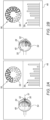
- FIGs. 2A-B are schematic illustrations of an iterative process for facilitating an ablation, in accordance with some examples of the present disclosure.
- processor 40 ( Fig. 1 ) continually ascertains the number of electrodes contacting tissue. For example, for each electrode, the processor may receive an impedance-indicating, force-indicating, or temperature-indicating signal. If the indicated impedance or force exceeds a threshold, or if the indicated temperature is below a threshold, the electrode may be deemed to be contacting tissue.
- a threshold number of electrodes is defined.
- This predefined threshold referred to herein as a "lower threshold,” is the minimum number of electrodes that need to contact the tissue in order to assume that distal structure 22 is positioned at least partly within the ostium.
- the lower threshold is at least 20% of the total number of electrodes around the circumference of the distal structure.
- the processor In response to the number of contacting electrodes equaling or exceeding the lower threshold, the processor carries out an iterative process for increasing the number of electrodes that contact the ostium. During each iteration of the process, the processor compares the number of contacting electrodes to another predefined threshold, referred to herein as a "higher threshold.” In response to the number being less than the higher threshold, the processor computes an adjustment to the pose of the distal structure. The processor then displays, on display 48, a target-pose icon 44, which represents the distal structure, offset, per the adjustment, from a current-pose icon 49 representing the distal structure at the current pose of the distal structure.
- the current-pose icon may move - and hence, the offset may change - cyclically, due to the effect of respiratory motion on the pose of the distal structure.
- the processor may compute a translation, e.g., along the proximal-distal (or "longitudinal") axis 51 of the distal structure. (It is noted that proximal-distal axis 51 is typically not displayed.)
- the processor may compute a rotation, e.g., as further described below with reference to Fig. 4 .
- the processor may compute both a rotation and a translation.
- the two icons are rendered in three dimensions, so as to increase the clarity of the required pose adjustment.
- Target-pose icon 44 is typically displayed "behind" current-pose icon 49 as in Figs. 2A and 2B .
- the two icons are shaded or colored differently from one another, so as to facilitate differentiating between the two.
- current-pose icon 49 includes multiple electrode icons 54, which represent different respective electrodes 30 ( Fig. 1 ).
- the processor modifies (e.g., highlights or changes the color of) those electrode icons 54 representing electrodes in contact with the tissue.
- Current-pose icon 49 may be rendered from any suitable perspective.
- the perspective may be adjusted by the physician (or by any other user).
- the physician begins adjusting the pose of the distal structure while continuing to look at the display.
- the processor continually refreshes current-pose icon 49 so as to indicate the current pose of the distal structure.
- the current-pose icon overlaps the target-pose icon.
- target-pose icon 44 is refreshed.
- the pose of the distal structure may be incrementally adjusted until the number of contacting electrodes equals or exceeds the higher threshold.
- the processor displays an adjustment indicator 50 indicating the computed adjustment.
- the processor may display an arrow pointing in the direction of the translation.
- the arrow may begin at the base of the distal nose 52 of current-pose icon 49, and terminate at the base of distal nose 52 of target-pose icon 44.
- the processor displays a schematic rendering 56 of a cross-section through the distal structure at the electrodes.
- the electrodes are represented by different respective cross-sectional electrode icons 58, which may be numbered (e.g., as 1, 2, 3, 4, 5, 6, 7, 8, 9, 10) so as to indicate the electrode to which each cross-sectional electrode icon 58 corresponds.
- the processor modifies (e.g., highlights or changes the color of) those cross-sectional electrode icons 58 representing electrodes in contact with the tissue.
- the processor may display a graph 59 indicating a measure of contact (e.g., an impedance, force, or temperature) for each of the electrodes.
- a measure of contact e.g., an impedance, force, or temperature
- Fig. 3 is a flow diagram for an algorithm 60 for facilitating an ablation, in accordance with some examples of the present disclosure.
- Algorithm 60 may be executed by processor 40 ( Fig. 1 ).
- Algorithm 60 begins with an ascertaining step 62, at which the processor ascertains the numbers of electrodes contacting the tissue of the subject. Subsequently to ascertaining the number, the processor checks, at a checking step 64, whether the number is greater than the lower threshold. If not, the processor returns to ascertaining step 62, typically after a predefined delay. Otherwise, the processor begins execution of an iterative process.
- the iterative process begins at another checking step 66, at which the processor checks whether the number of contacting electrodes is greater than the higher threshold. If yes, execution of the algorithm ends. Otherwise, the processor computes and displays an adjustment to the pose of the distal structure, as described above with reference to Figs. 2A-B .
- the type of adjustment that is computed depends on the number of contacting electrodes. For example, if the number is less than a middle threshold, which is between the lower threshold and the higher threshold and in some examples is at least 50% of the total number of the electrodes around the circumference of the distal structure, the processor may compute a translation, as shown in Fig. 2A , at a translation-computing step 70. Otherwise, the processor may compute a rotation, as shown in Fig. 2B , at a rotation-computing step 72.
- the pose adjustment computed by the processor is relatively small.
- the translation computed at translation-computing step 70 may be less than 5 mm, and/or the rotation computed at rotation-computing step 72 may be less than 10 degrees.
- the pose of the distal structure may be adjusted incrementally.
- the processor displays the target-pose icon, at an icon-displaying step 73, so as to indicate the adjustment.
- the processor continually checks, at another checking step 74, whether the current pose matches, i.e., is within a predefined threshold of, the target pose.
- the processor continually refreshes current-pose icon 49 ( Figs. 2A-B ) so as to indicate any changes to the pose of the distal structure.
- the processor In response to the current pose matching the target pose, the processor again performs ascertaining step 62, and then returns to checking step 66 for the next iteration of the process.
- FIG. 4 is a schematic illustration of a rotation computation, in accordance with some examples of the present disclosure.
- the processor first computes a centroid M of those of the electrodes contacting the ostium and a centroid C of distal structure 22 of the catheter, e.g., of expandable member 25 ( Fig. 1 ).
- the processor may assign a uniform weight to distal structure 22, including electrodes 30.
- the processor may assign different weights to different respective portions of the distal structure.
- the processor may assign a respective weight to each of electrodes 30 contacting the ostium as an increasing function (e.g., an increasing linear function) of a degree to which the electrode contacts the ostium.
- the weight may be an increasing function of the impedance seen by the electrode and/or the force applied to the electrode, and/or a decreasing function of the temperature measured at electrode 30.
- the processor computes a normal vector N , which is normal to a hypothetical plane 76 tangent to the distal structure at the centroid M.
- the processor further computes an axis-of-rotation vector R as N ⁇ ( C - M ) .
- the processor computes the rotation about R , as indicated in Fig. 4 by a rotation indicator 78.
- the rotation is toward the distal end of distal structure 22, such as toward distal nose 52 ( Fig. 2B ).
- a system (20) for use with a catheter (24) having a distal structure (22) including a plurality of electrodes (30) includes a display (48) and a processor (40).
- the processor is configured to ascertain a number of the plurality of electrodes of the distal structure contacting an ostium of a pulmonary vein (32), and in response to the number equaling or exceeding a predefined lower threshold, carry out an iterative process.
- the process includes, during each iteration of the process, in response to the number being less than a predefined higher threshold, computing an adjustment to a current pose of the distal structure, and displaying, on the display, a target-pose icon (44), which represents the distal structure, offset, per the adjustment, from the current-pose icon (49) representing the distal structure at the current pose.
- Example 1 The system (20) according to Example 1, wherein the displaying includes rendering the target-pose icon (44) and the current-pose icon (49) in three dimensions.
- computing the first centroid includes assigning a respective weight to each of the electrodes (30) contacting the ostium as an increasing function of a degree to which the electrode contacts the ostium.
- a method for use with a catheter (24) having a distal structure (22) including a plurality of electrodes (30) includes ascertaining a number of the plurality of electrodes contacting an ostium of a pulmonary vein (32). The method further includes, in response to the number of electrodes equaling or exceeding a predefined lower threshold, carrying out an iterative process. The process includes, during each iteration of the process, in response to the number being less than a predefined higher threshold, computing an adjustment to a current pose of the distal structure, and displaying a target-pose icon (44), which represents the distal structure, offset, per the adjustment, from a current-pose icon (49) representing the distal structure at the current pose.
- Example 11 wherein the displaying comprises rendering the target-pose icon (44) and the current-pose icon (49) in three dimensions.
- Example 11 wherein the lower threshold is at least 20% of a total number of the electrodes (30) around a circumference of the distal structure (22).
- computing the adjustment comprises:
- Example 14 The method according to Example 14, wherein the translation is along a proximal-distal axis (51) of the distal structure (22).
- computing the first centroid comprises computing the first centroid by assigning a respective weight to each of the electrodes (30) contacting the ostium as an increasing function of a degree to which the electrode contacts the ostium.
- Example 14 The method according to Example 14, wherein the translation is less than 5 mm.
Landscapes
- Health & Medical Sciences (AREA)
- Engineering & Computer Science (AREA)
- Surgery (AREA)
- Life Sciences & Earth Sciences (AREA)
- Veterinary Medicine (AREA)
- General Health & Medical Sciences (AREA)
- Nuclear Medicine, Radiotherapy & Molecular Imaging (AREA)
- Public Health (AREA)
- Biomedical Technology (AREA)
- Heart & Thoracic Surgery (AREA)
- Medical Informatics (AREA)
- Molecular Biology (AREA)
- Animal Behavior & Ethology (AREA)
- Otolaryngology (AREA)
- Plasma & Fusion (AREA)
- Physics & Mathematics (AREA)
- Robotics (AREA)
- Cardiology (AREA)
- Human Computer Interaction (AREA)
- Measurement And Recording Of Electrical Phenomena And Electrical Characteristics Of The Living Body (AREA)
- Surgical Instruments (AREA)
Abstract
Description
- The present disclosure is related generally to the field of electrophysiology, and particularly to computer-implemented techniques for facilitating an electrophysiological procedure.
- In some electrophysiological procedures, a pulmonary vein is electrically isolated from the myocardium by the ablation of tissue at the ostium of the vein.
- The present disclosure will be more fully understood from the following detailed description of examples thereof, taken together with the drawings, in which:
-
Fig. 1 is a schematic illustration of an ablation system, in accordance with some examples of the present disclosure; -
Figs. 2A-B are schematic illustrations of an iterative process for facilitating an ablation, in accordance with some examples of the present disclosure; -
Fig. 3 is a flow diagram for an algorithm for facilitating an ablation, in accordance with some examples of the present disclosure; and -
Fig. 4 is a schematic illustration of a rotation computation, in accordance with some examples of the present disclosure. - In the context of the present application, including the claims, the "pose" of an object refers to a combination of the location and orientation of the object with respect to a referential datum, such that a first pose may differ from a second pose by a translation and/or a rotation.
- In some cases, an intrabody ablation catheter is used to ablate the ostium of a pulmonary vein. Such a catheter typically comprises a distal structure, such as a balloon, having a plurality of electrodes disposed thereon. The electrodes are typically arranged (e.g., evenly distributed) around the circumference of the structure.
- In such cases, it is typically desirable to contact the ostium with as many of the electrodes as possible, so as to ablate around the full circumference of the ostium. However, even with continual updates as to the number of electrodes contacting the ostium, it may be difficult for the physician to determine the required adjustments to the pose of the structure.
- To address this challenge, examples of the present disclosure provide a processor configured to compute, repeatedly, a relatively small pose adjustment, such as a translation or rotation, that is likely to increase the number of contacting electrodes. After each computation, the processor displays two icons, each of which represents the structure and is typically rendered in three dimensions. One of the icons, a "target-pose icon," is offset from the other icon, a "current-pose icon," per the computed adjustment. The physician may then adjust the pose of the structure, while viewing the display, so as to bring the current-pose icon into alignment with the target-pose icon.
- As the present inventors have observed, a smaller number of contacting electrodes generally indicates that the structure has not fully entered the ostium, whereas a greater number of contacting electrodes generally indicates that the structure has fully entered the ostium but is not optimally oriented. Hence, in some examples, the processor compares the number of contacting electrodes to a predefined threshold. If the number is less than the threshold, the processor computes a translation of the distal structure, typically along the proximal-distal axis of the structure. Otherwise, the processor computes a rotation with respect to the proximal-distal axis or with respect to another referential axis defined by the distal structure.
- Reference is initially made to
Fig. 1 , which is a schematic illustration of anablation system 20, in accordance with some examples of the present disclosure. -
System 20 comprises acatheter 24 configured for insertion into the body of asubject 26 by aphysician 28.System 20 further comprises aconsole 46 comprisingcontrols 39 for controllingsystem 20, and adisplay 48, which is typically mounted onconsole 46. -
System 20 further comprises aprocessor 40 and asignal generator 42, which are typically contained withinconsole 46.System 20 may further comprise a volatile memory, a non-volatile memory, a noise filter, an analog-to-digital (A/D) converter, and/or any other suitable circuitry. - The distal end of
catheter 24 comprises a distal structure 22 comprisingmultiple electrodes 30, each of which is connected tosignal generator 42 via a wire passing throughcatheter 24. Typically, distal structure 22 comprises an expandable member 25, such as a balloon (as shown inFig. 1 ), an expandable basket of spines, or an expandable planar structure.Electrodes 30 are typically distributed around the circumference or perimeter of distal structure 22. - Subsequently to inserting
catheter 24 into the body ofsubject 26,physician 28 navigates distal structure 22 ofcatheter 24 to the left atrium of theheart 34 of the subject. Subsequently, with the help of processor 40 (as described below with reference to the subsequent figures), the physician positions distal structure 22 within the ostium of apulmonary vein 32. Subsequently, usingcontrols 39, the physician causessignal generator 42 to generate ablating signals, such that the ablating signals pass through the tissue of the ostium viaelectrodes 30. -
Processor 40 is configured to track the pose of distal structure 22. - For example, distal structure 22 may comprise one or more electromagnetic sensors connected to
console 46, andsystem 20 may further comprise one or more magnetic-field generators configured to generate a magnetic field as a referential datum. In particular, the magnetic field may induce tracking signals in the electromagnetic sensors so that the positions of the sensors can be triangulated, and hence determined with respect to the referential datum. In other words, based on the tracking signals,processor 40 may ascertain the respective locations of the sensors with respect to the referential datum, and hence, the pose of the distal structure. Such location-tracking techniques are well known and previously disclosed, for example, inUS Patents 5,391,199 ,5,443,489 , and6,788,967 to Ben-Haim , inUS Patent 6,690,963 to Ben-Haim et al. , inUS Patent 5,558,091 to Acker et al. , and inUS Patent 6,177,792 to Govari , which are hereby incorporated by reference into this application. - Alternatively or additionally,
system 20 may further comprise one ormore reference electrodes 29 coupled to the surface of the body of the subject and connected toconsole 46 via acable 36. Electric currents at predefined frequencies forelectrodes 30 may be passed between electrodes 30 (and/or other electrodes on the distal structure) andreference electrodes 29. Based on the resulting impedances measured byreference electrodes 29,processor 40 may ascertain the respective locations ofelectrodes 30 and hence, the pose of the distal structure, by triangulation of the impedance values withreference electrodes 29. Such techniques may utilize a location map calibrated, in advance, using electromagnetic sensors, as described, for example, inUS Patent 7,536,218 to Govari et al. andUS Patent 8,456,182 to Bar-Tal et al. - Alternatively or additionally, electric currents may be passed between
reference electrodes 29. Based on the resulting voltages at electrodes 30 (and/or other electrodes on the distal structure),processor 40 may ascertain the respective locations ofelectrodes 30, and hence, the pose of the distal structure. Such techniques are described, for example, inUS Patent 5,983,126 to Wittkampf andUS Patent 5,944,022 to Nardella . - In some examples,
system 20 further comprises one or more electrocardiogram (ECG) electrodes, which are electrically coupled to the skin ofsubject 26.Processor 40 may receive the ECG signals acquired by the ECG electrodes via a cable connected toconsole 46. - While distal structure 22 is within
heart 34, the processor receives signals indicating the degree to which eachelectrode 30 is in contact with the tissue. For example, the signals may indicate the impedance seen by each electrode. (The impedance of tissue is greater than that of blood, such that a higher impedance indicates greater contact.) Alternatively or additionally, the signals may indicate the temperature measured by thermocouples co-located with the electrodes. (Typically, a lower temperature indicates greater contact, due to less blood flow near the thermocouples and hence, less heating of the thermocouples by blood.) Alternatively or additionally, the signals may indicate a force or pressure measured by sensors co-located with the electrodes. - In general,
processor 40 may be embodied as a single processor, or as a cooperatively networked or clustered set of processors. The functionality ofprocessor 40 may be implemented solely in hardware, e.g., using one or more fixed-function or general-purpose integrated circuits, Application-Specific Integrated Circuits (ASICs), and/or Field-Programmable Gate Arrays (FPGAs). Alternatively, this functionality may be implemented at least partly in software. For example,processor 40 may be embodied as a programmed processor comprising, for example, a central processing unit (CPU) and/or a Graphics Processing Unit (GPU). Program code, including software programs, and/or data may be loaded for execution and processing by the CPU and/or GPU. The program code and/or data may be downloaded to the processor in electronic form, over a network, for example. Alternatively or additionally, the program code and/or data may be provided and/or stored on non-transitory tangible media, such as magnetic, optical, or electronic memory. Such program code and/or data, when provided to the processor, produce a machine or special-purpose computer, configured to perform the tasks described herein. - Reference is now made to
Figs. 2A-B , which are schematic illustrations of an iterative process for facilitating an ablation, in accordance with some examples of the present disclosure. - In general, for an ablation of a pulmonary vein, it is best to maximize the number of electrodes 30 (
Fig. 1 ) that contact the ostium of the vein. To facilitate this maximizing, processor 40 (Fig. 1 ) continually ascertains the number of electrodes contacting tissue. For example, for each electrode, the processor may receive an impedance-indicating, force-indicating, or temperature-indicating signal. If the indicated impedance or force exceeds a threshold, or if the indicated temperature is below a threshold, the electrode may be deemed to be contacting tissue. - Prior to the procedure, a threshold number of electrodes is defined. This predefined threshold, referred to herein as a "lower threshold," is the minimum number of electrodes that need to contact the tissue in order to assume that distal structure 22 is positioned at least partly within the ostium. Typically, the lower threshold is at least 20% of the total number of electrodes around the circumference of the distal structure.
- In response to the number of contacting electrodes equaling or exceeding the lower threshold, the processor carries out an iterative process for increasing the number of electrodes that contact the ostium. During each iteration of the process, the processor compares the number of contacting electrodes to another predefined threshold, referred to herein as a "higher threshold." In response to the number being less than the higher threshold, the processor computes an adjustment to the pose of the distal structure. The processor then displays, on
display 48, a target-pose icon 44, which represents the distal structure, offset, per the adjustment, from a current-pose icon 49 representing the distal structure at the current pose of the distal structure. (Subsequently to the initial display of current-pose icon 49 and target-pose icon 44, the current-pose icon may move - and hence, the offset may change - cyclically, due to the effect of respiratory motion on the pose of the distal structure.) - For example, as shown in
Fig. 2A , the processor may compute a translation, e.g., along the proximal-distal (or "longitudinal")axis 51 of the distal structure. (It is noted that proximal-distal axis 51 is typically not displayed.) Alternatively, as shown inFig. 2B , the processor may compute a rotation, e.g., as further described below with reference toFig. 4 . Alternatively, the processor may compute both a rotation and a translation. - Typically, the two icons are rendered in three dimensions, so as to increase the clarity of the required pose adjustment. Target-
pose icon 44 is typically displayed "behind" current-pose icon 49 as inFigs. 2A and 2B . In some embodiments, the two icons are shaded or colored differently from one another, so as to facilitate differentiating between the two. - Typically, current-
pose icon 49 includesmultiple electrode icons 54, which represent different respective electrodes 30 (Fig. 1 ). In some examples, the processor modifies (e.g., highlights or changes the color of) those electrodeicons 54 representing electrodes in contact with the tissue. - Current-
pose icon 49 may be rendered from any suitable perspective. In some examples, the perspective may be adjusted by the physician (or by any other user). - In response to viewing target-
pose icon 44, the physician begins adjusting the pose of the distal structure while continuing to look at the display. During the adjustment, the processor continually refreshes current-pose icon 49 so as to indicate the current pose of the distal structure. Upon the distal structure reaching the target pose, the current-pose icon overlaps the target-pose icon. - Subsequently, the next iteration of the iterative process begins, and target-
pose icon 44 is refreshed. In this manner, the pose of the distal structure may be incrementally adjusted until the number of contacting electrodes equals or exceeds the higher threshold. - In some examples, the processor displays an
adjustment indicator 50 indicating the computed adjustment. For example, as shown inFig. 2A , for a translation, the processor may display an arrow pointing in the direction of the translation. For a translation along proximal-distal axis 51, the arrow may begin at the base of thedistal nose 52 of current-pose icon 49, and terminate at the base ofdistal nose 52 of target-pose icon 44. - Typically, the processor displays a
schematic rendering 56 of a cross-section through the distal structure at the electrodes. Inrendering 56, the electrodes are represented by different respectivecross-sectional electrode icons 58, which may be numbered (e.g., as 1, 2, 3, 4, 5, 6, 7, 8, 9, 10) so as to indicate the electrode to which eachcross-sectional electrode icon 58 corresponds. In some examples, the processor modifies (e.g., highlights or changes the color of) thosecross-sectional electrode icons 58 representing electrodes in contact with the tissue. - Alternatively or additionally, the processor may display a
graph 59 indicating a measure of contact (e.g., an impedance, force, or temperature) for each of the electrodes. - Reference is now made to
Fig. 3 , which is a flow diagram for analgorithm 60 for facilitating an ablation, in accordance with some examples of the present disclosure.Algorithm 60 may be executed by processor 40 (Fig. 1 ). -
Algorithm 60 begins with an ascertainingstep 62, at which the processor ascertains the numbers of electrodes contacting the tissue of the subject. Subsequently to ascertaining the number, the processor checks, at a checkingstep 64, whether the number is greater than the lower threshold. If not, the processor returns to ascertainingstep 62, typically after a predefined delay. Otherwise, the processor begins execution of an iterative process. - The iterative process begins at another checking
step 66, at which the processor checks whether the number of contacting electrodes is greater than the higher threshold. If yes, execution of the algorithm ends. Otherwise, the processor computes and displays an adjustment to the pose of the distal structure, as described above with reference toFigs. 2A-B . - Typically, the type of adjustment that is computed depends on the number of contacting electrodes. For example, if the number is less than a middle threshold, which is between the lower threshold and the higher threshold and in some examples is at least 50% of the total number of the electrodes around the circumference of the distal structure, the processor may compute a translation, as shown in
Fig. 2A , at a translation-computing step 70. Otherwise, the processor may compute a rotation, as shown inFig. 2B , at a rotation-computing step 72. - Typically, the pose adjustment computed by the processor is relatively small. For example, the translation computed at translation-computing step 70 may be less than 5 mm, and/or the rotation computed at rotation-
computing step 72 may be less than 10 degrees. Thus, advantageously, the pose of the distal structure may be adjusted incrementally. - Subsequently to computing the pose adjustment, the processor displays the target-pose icon, at an icon-displaying
step 73, so as to indicate the adjustment. Next, as the physician adjusts the pose of the distal structure, the processor continually checks, at another checkingstep 74, whether the current pose matches, i.e., is within a predefined threshold of, the target pose. Typically, while the continual checking is performed, the processor continually refreshes current-pose icon 49 (Figs. 2A-B ) so as to indicate any changes to the pose of the distal structure. - In response to the current pose matching the target pose, the processor again performs ascertaining
step 62, and then returns to checkingstep 66 for the next iteration of the process. - Reference is now made to
Fig. 4 , which is a schematic illustration of a rotation computation, in accordance with some examples of the present disclosure. - In some examples, to compute a rotation, the processor first computes a centroid M of those of the electrodes contacting the ostium and a centroid C of distal structure 22 of the catheter, e.g., of expandable member 25 (
Fig. 1 ). In computing these centroids, the processor may assign a uniform weight to distal structure 22, includingelectrodes 30. Alternatively, for at least one of the centroid computations, the processor may assign different weights to different respective portions of the distal structure. For example, in computing M, the processor may assign a respective weight to each ofelectrodes 30 contacting the ostium as an increasing function (e.g., an increasing linear function) of a degree to which the electrode contacts the ostium. For example, the weight may be an increasing function of the impedance seen by the electrode and/or the force applied to the electrode, and/or a decreasing function of the temperature measured atelectrode 30. - Subsequently, the processor computes a normal vector
N , which is normal to a hypothetical plane 76 tangent to the distal structure at the centroid M. The processor further computes an axis-of-rotation vectorR asN ×(C - M) . Finally, the processor computes the rotation aboutR , as indicated inFig. 4 by a rotation indicator 78. Typically, the rotation is toward the distal end of distal structure 22, such as toward distal nose 52 (Fig. 2B ). - The following examples relate to various non-exhaustive ways in which the teachings herein may be combined or applied. It should be understood that the following examples are not intended to restrict the coverage of any claims that may be presented at any time in this application or in subsequent filings of this application. No disclaimer is intended. The following examples are being provided for nothing more than merely illustrative purposes. It is contemplated that the various teachings herein may be arranged and applied in numerous other ways. It is also contemplated that some variations may omit certain features referred to in the below examples. Therefore, none of the aspects or features referred to below should be deemed critical unless otherwise explicitly indicated as such at a later date by the inventors or by a successor in interest to the inventors. If any claims are presented in this application or in subsequent filings related to this application that include additional features beyond those referred to below, those additional features shall not be presumed to have been added for any reason relating to patentability.
- A system (20) for use with a catheter (24) having a distal structure (22) including a plurality of electrodes (30) includes a display (48) and a processor (40). The processor is configured to ascertain a number of the plurality of electrodes of the distal structure contacting an ostium of a pulmonary vein (32), and in response to the number equaling or exceeding a predefined lower threshold, carry out an iterative process. The process includes, during each iteration of the process, in response to the number being less than a predefined higher threshold, computing an adjustment to a current pose of the distal structure, and displaying, on the display, a target-pose icon (44), which represents the distal structure, offset, per the adjustment, from the current-pose icon (49) representing the distal structure at the current pose.
- The system (20) according to Example 1, wherein the displaying includes rendering the target-pose icon (44) and the current-pose icon (49) in three dimensions.
- The system (20) according to Example 1, wherein the lower threshold is at least 20% of a total number of the electrodes (30) around a circumference of the distal structure (22).
- The system (20) according to any one of Examples 1-3, wherein computing the adjustment includes:
- computing a translation of the distal structure in case the number is less than a predefined middle threshold, which is between the lower threshold and the higher threshold, or
- computing a rotation of the distal structure in case the number is equal to or greater than the middle threshold.
- The system (20) according to Example 4, wherein the translation is along a proximal-distal axis (51) of the distal structure (22).
- The system (20) according to Example 4, wherein the middle threshold is at least 50% of a total number of the electrodes (30) around a circumference of the distal structure (22).
- The system (20) according to Example 4, wherein computing the rotation includes:
- computing a first centroid M of those of the plurality of electrodes (30) contacting the ostium and a second centroid C of the distal structure (22),
- computing a normal vector
N , which is normal to a hypothetical plane (76) tangent to the distal structure at the first centroid, - computing an axis-of-rotation vector
R asN ×(C - M) , and - computing the rotation about
R . - The system (20) according to Example 7, wherein computing the first centroid includes assigning a respective weight to each of the electrodes (30) contacting the ostium as an increasing function of a degree to which the electrode contacts the ostium.
- The system according to Example 4, wherein the translation is less than 5 mm.
- The system according to Example 4, wherein the rotation is less than 10 degrees.
- A method for use with a catheter (24) having a distal structure (22) including a plurality of electrodes (30) includes ascertaining a number of the plurality of electrodes contacting an ostium of a pulmonary vein (32). The method further includes, in response to the number of electrodes equaling or exceeding a predefined lower threshold, carrying out an iterative process. The process includes, during each iteration of the process, in response to the number being less than a predefined higher threshold, computing an adjustment to a current pose of the distal structure, and displaying a target-pose icon (44), which represents the distal structure, offset, per the adjustment, from a current-pose icon (49) representing the distal structure at the current pose.
- The method according to Example 11, wherein the displaying comprises rendering the target-pose icon (44) and the current-pose icon (49) in three dimensions.
- The method according to Example 11, wherein the lower threshold is at least 20% of a total number of the electrodes (30) around a circumference of the distal structure (22).
- The method according to any one of Examples 11-13, wherein computing the adjustment comprises:
- computing a translation provided the number is less than a predefined middle threshold, which is between the lower threshold and the higher threshold; or
- computing a rotation provided the number is equal to or greater than the middle threshold.
- The method according to Example 14, wherein the translation is along a proximal-distal axis (51) of the distal structure (22).
- The method according to Example 14, wherein the middle threshold is at least 50% of a total number of the electrodes (30) around a circumference of the distal structure (22).
- The method according to Example 14, wherein computing the rotation comprises:
- computing a first centroid M of those of the electrodes (30) contacting the ostium and a second centroid C of the distal structure (22);
- computing a normal vector
N , which is normal to a hypothetical plane (76) tangent to the distal structure at the first centroid; - computing an axis-of-rotation vector
R asN x(C - M) ; and - computing the rotation about
R . - The method according to Example 17, wherein computing the first centroid comprises computing the first centroid by assigning a respective weight to each of the electrodes (30) contacting the ostium as an increasing function of a degree to which the electrode contacts the ostium.
- The method according to Example 14, wherein the translation is less than 5 mm.
- The method according to Example 14, wherein the rotation is less than 10 degrees.
- It will be appreciated by persons skilled in the art that the present disclosure is not limited to what has been particularly shown and described hereinabove. Rather, the scope of examples of the present disclosure includes both combinations and subcombinations of the various features described hereinabove, as well as variations and modifications thereof that are not in the prior art, which would occur to persons skilled in the art upon reading the foregoing description.
Claims (10)
- A system (20) for use with a catheter (24) having a distal structure (22) including a plurality of electrodes (30), the system comprising:a display (48); anda processor (40), configured to:ascertain a number of the plurality of electrodes of the distal structure contacting an ostium of a pulmonary vein (32), andin response to the number equaling or exceeding a predefined lower threshold, carry out an iterative process including, during each iteration of the process:in response to the number being less than a predefined higher threshold, computing an adjustment to a current pose of the distal structure, anddisplaying, on the display, a target-pose icon (44), which represents the distal structure, offset, per the adjustment, from a current-pose icon (49) representing the distal structure at the current pose.
- The system (20) according to claim 1, wherein the displaying includes rendering the target-pose icon (44) and the current-pose icon (49) in three dimensions.
- The system (20) according to claim 1, wherein the lower threshold is at least 20% of a total number of the electrodes (30) around a circumference of the distal structure (22).
- The system (20) according to any preceding claim, wherein computing the adjustment includes:computing a translation of the distal structure in case the number is less than a predefined middle threshold, which is between the lower threshold and the higher threshold, orcomputing a rotation of the distal structure in case the number is equal to or greater than the middle threshold.
- The system (20) according to claim 4, wherein the translation is along a proximal-distal axis (51) of the distal structure (22).
- The system (20) according to claim 4, wherein the middle threshold is at least 50% of a total number of the electrodes (30) around a circumference of the distal structure (22).
- The system (20) according to claim 4, wherein computing the rotation includes:computing a first centroid M of those of the plurality of electrodes (30) contacting the ostium and a second centroid C of the distal structure (22),computing a normal vector
N , which is normal to a hypothetical plane (76) tangent to the distal structure at the first centroid,computing an axis-of-rotation vectorR asN x(C - M) , andcomputing the rotation aboutR . - The system (20) according to claim 7, wherein computing the first centroid includes assigning a respective weight to each of the electrodes (30) contacting the ostium as an increasing function of a degree to which the electrode contacts the ostium.
- The system according to claim 4, wherein the translation is less than 5 mm.
- The system according to claim 4, wherein the rotation is less than 10 degrees.
Applications Claiming Priority (1)
| Application Number | Priority Date | Filing Date | Title |
|---|---|---|---|
| US17/986,854 US20240156520A1 (en) | 2022-11-14 | 2022-11-14 | Guidance for Positioning an Ablation Catheter |
Publications (1)
| Publication Number | Publication Date |
|---|---|
| EP4374810A1 true EP4374810A1 (en) | 2024-05-29 |
Family
ID=88793240
Family Applications (1)
| Application Number | Title | Priority Date | Filing Date |
|---|---|---|---|
| EP23209303.9A Pending EP4374810A1 (en) | 2022-11-14 | 2023-11-13 | Guidance for positioning an ablation catheter |
Country Status (5)
| Country | Link |
|---|---|
| US (1) | US20240156520A1 (en) |
| EP (1) | EP4374810A1 (en) |
| JP (1) | JP2024071364A (en) |
| CN (1) | CN118021444A (en) |
| IL (1) | IL308352A (en) |
Cited By (1)
| Publication number | Priority date | Publication date | Assignee | Title |
|---|---|---|---|---|
| EP4740883A1 (en) * | 2024-11-11 | 2026-05-13 | Biosense Webster (Israel) Ltd. | Tissue proximity indicator threshold for cardiac ablation |
Citations (15)
| Publication number | Priority date | Publication date | Assignee | Title |
|---|---|---|---|---|
| US5391199A (en) | 1993-07-20 | 1995-02-21 | Biosense, Inc. | Apparatus and method for treating cardiac arrhythmias |
| US5558091A (en) | 1993-10-06 | 1996-09-24 | Biosense, Inc. | Magnetic determination of position and orientation |
| US5944022A (en) | 1997-04-28 | 1999-08-31 | American Cardiac Ablation Co. Inc. | Catheter positioning system |
| US5983126A (en) | 1995-11-22 | 1999-11-09 | Medtronic, Inc. | Catheter location system and method |
| US6177792B1 (en) | 1996-03-26 | 2001-01-23 | Bisense, Inc. | Mutual induction correction for radiator coils of an objects tracking system |
| US6690963B2 (en) | 1995-01-24 | 2004-02-10 | Biosense, Inc. | System for determining the location and orientation of an invasive medical instrument |
| US20050033281A1 (en) * | 2002-05-23 | 2005-02-10 | Adiana, Inc. | Catheter placement detection system and operator interface |
| US7536218B2 (en) | 2005-07-15 | 2009-05-19 | Biosense Webster, Inc. | Hybrid magnetic-based and impedance-based position sensing |
| US8456182B2 (en) | 2008-09-30 | 2013-06-04 | Biosense Webster, Inc. | Current localization tracker |
| US20130150693A1 (en) * | 2011-08-05 | 2013-06-13 | Robert D'Angelo | Catheter balloon methods and apparatus employing sensing elements |
| US20200022653A1 (en) * | 2018-07-20 | 2020-01-23 | Kardium Inc. | Systems and methods for facilitating improved transducer-to-tissue contact |
| US20200030028A1 (en) * | 2013-03-15 | 2020-01-30 | Medtronic Ardian Luxembourg S.A.R.L. | Multi-Electrode Apposition Judgment Using Pressure Elements |
| EP3791819A1 (en) * | 2019-09-12 | 2021-03-17 | Biosense Webster (Israel) Ltd | Graphical user interface for an multi-electrode ablation system |
| US20220047326A1 (en) * | 2020-08-13 | 2022-02-17 | Biosense Webster (Israel) Ltd. | Applying Bipolar Ablation Energy Between Shorted Electrode Groups |
| US20220192753A1 (en) * | 2020-12-22 | 2022-06-23 | Biosense Webster (Israel) Ltd. | Distal End Assembly Guidance |
-
2022
- 2022-11-14 US US17/986,854 patent/US20240156520A1/en active Pending
-
2023
- 2023-11-07 IL IL308352A patent/IL308352A/en unknown
- 2023-11-13 EP EP23209303.9A patent/EP4374810A1/en active Pending
- 2023-11-13 JP JP2023192948A patent/JP2024071364A/en active Pending
- 2023-11-14 CN CN202311511789.2A patent/CN118021444A/en active Pending
Patent Citations (17)
| Publication number | Priority date | Publication date | Assignee | Title |
|---|---|---|---|---|
| US5391199A (en) | 1993-07-20 | 1995-02-21 | Biosense, Inc. | Apparatus and method for treating cardiac arrhythmias |
| US5443489A (en) | 1993-07-20 | 1995-08-22 | Biosense, Inc. | Apparatus and method for ablation |
| US5558091A (en) | 1993-10-06 | 1996-09-24 | Biosense, Inc. | Magnetic determination of position and orientation |
| US6690963B2 (en) | 1995-01-24 | 2004-02-10 | Biosense, Inc. | System for determining the location and orientation of an invasive medical instrument |
| US5983126A (en) | 1995-11-22 | 1999-11-09 | Medtronic, Inc. | Catheter location system and method |
| US6177792B1 (en) | 1996-03-26 | 2001-01-23 | Bisense, Inc. | Mutual induction correction for radiator coils of an objects tracking system |
| US5944022A (en) | 1997-04-28 | 1999-08-31 | American Cardiac Ablation Co. Inc. | Catheter positioning system |
| US6788967B2 (en) | 1997-05-14 | 2004-09-07 | Biosense, Inc. | Medical diagnosis, treatment and imaging systems |
| US20050033281A1 (en) * | 2002-05-23 | 2005-02-10 | Adiana, Inc. | Catheter placement detection system and operator interface |
| US7536218B2 (en) | 2005-07-15 | 2009-05-19 | Biosense Webster, Inc. | Hybrid magnetic-based and impedance-based position sensing |
| US8456182B2 (en) | 2008-09-30 | 2013-06-04 | Biosense Webster, Inc. | Current localization tracker |
| US20130150693A1 (en) * | 2011-08-05 | 2013-06-13 | Robert D'Angelo | Catheter balloon methods and apparatus employing sensing elements |
| US20200030028A1 (en) * | 2013-03-15 | 2020-01-30 | Medtronic Ardian Luxembourg S.A.R.L. | Multi-Electrode Apposition Judgment Using Pressure Elements |
| US20200022653A1 (en) * | 2018-07-20 | 2020-01-23 | Kardium Inc. | Systems and methods for facilitating improved transducer-to-tissue contact |
| EP3791819A1 (en) * | 2019-09-12 | 2021-03-17 | Biosense Webster (Israel) Ltd | Graphical user interface for an multi-electrode ablation system |
| US20220047326A1 (en) * | 2020-08-13 | 2022-02-17 | Biosense Webster (Israel) Ltd. | Applying Bipolar Ablation Energy Between Shorted Electrode Groups |
| US20220192753A1 (en) * | 2020-12-22 | 2022-06-23 | Biosense Webster (Israel) Ltd. | Distal End Assembly Guidance |
Cited By (1)
| Publication number | Priority date | Publication date | Assignee | Title |
|---|---|---|---|---|
| EP4740883A1 (en) * | 2024-11-11 | 2026-05-13 | Biosense Webster (Israel) Ltd. | Tissue proximity indicator threshold for cardiac ablation |
Also Published As
| Publication number | Publication date |
|---|---|
| US20240156520A1 (en) | 2024-05-16 |
| IL308352A (en) | 2024-06-01 |
| JP2024071364A (en) | 2024-05-24 |
| CN118021444A (en) | 2024-05-14 |
Similar Documents
| Publication | Publication Date | Title |
|---|---|---|
| US12539085B2 (en) | Accurate basket catheter tracking | |
| EP3629987B1 (en) | Catheter splines as location sensors | |
| EP3571989B1 (en) | Scaling impedance location measurements of a balloon catheter | |
| EP4183342B1 (en) | Mapping system with realtime electrogram overlay | |
| US20240156520A1 (en) | Guidance for Positioning an Ablation Catheter | |
| EP3409188B1 (en) | System for identifying contact with tissue using a piecewise-linear model of a catheter arm | |
| US11771373B2 (en) | Staggered electrode arrangements for electrophysiological sensing | |
| CN110613453B (en) | Identifying an orthogonal set of Active Current Location (ACL) patches | |
| EP3381358A1 (en) | Sensor for facilitating catheter visualization | |
| IL296928A (en) | Forecasted electroanatomical maps for ablation planning | |
| EP4389004A1 (en) | Detecting local activation source in atrial fibrillation | |
| CN112955090A (en) | Apparatus, system and method for improving accuracy and practicality of cardiovascular procedure imaging | |
| US11484369B2 (en) | Identifying instances of cardioversion while building a position map | |
| WO2025144812A1 (en) | Catheter assembly tracking | |
| EP4555487A1 (en) | Correcting a segmentation curve in an anatomical model |
Legal Events
| Date | Code | Title | Description |
|---|---|---|---|
| PUAI | Public reference made under article 153(3) epc to a published international application that has entered the european phase |
Free format text: ORIGINAL CODE: 0009012 |
|
| STAA | Information on the status of an ep patent application or granted ep patent |
Free format text: STATUS: THE APPLICATION HAS BEEN PUBLISHED |
|
| AK | Designated contracting states |
Kind code of ref document: A1 Designated state(s): AL AT BE BG CH CY CZ DE DK EE ES FI FR GB GR HR HU IE IS IT LI LT LU LV MC ME MK MT NL NO PL PT RO RS SE SI SK SM TR |
|
| STAA | Information on the status of an ep patent application or granted ep patent |
Free format text: STATUS: REQUEST FOR EXAMINATION WAS MADE |
|
| 17P | Request for examination filed |
Effective date: 20241128 |
|
| RBV | Designated contracting states (corrected) |
Designated state(s): AL AT BE BG CH CY CZ DE DK EE ES FI FR GB GR HR HU IE IS IT LI LT LU LV MC ME MK MT NL NO PL PT RO RS SE SI SK SM TR |
|
| STAA | Information on the status of an ep patent application or granted ep patent |
Free format text: STATUS: EXAMINATION IS IN PROGRESS |
|
| 17Q | First examination report despatched |
Effective date: 20250611 |