EP4374794A2 - Surgical dilators and assemblies and methods thereof - Google Patents
Surgical dilators and assemblies and methods thereof Download PDFInfo
- Publication number
- EP4374794A2 EP4374794A2 EP24151223.5A EP24151223A EP4374794A2 EP 4374794 A2 EP4374794 A2 EP 4374794A2 EP 24151223 A EP24151223 A EP 24151223A EP 4374794 A2 EP4374794 A2 EP 4374794A2
- Authority
- EP
- European Patent Office
- Prior art keywords
- major
- lead
- minor
- cutting edge
- base
- Prior art date
- Legal status (The legal status is an assumption and is not a legal conclusion. Google has not performed a legal analysis and makes no representation as to the accuracy of the status listed.)
- Pending
Links
Images




Classifications
-
- A—HUMAN NECESSITIES
- A61—MEDICAL OR VETERINARY SCIENCE; HYGIENE
- A61M—DEVICES FOR INTRODUCING MEDIA INTO, OR ONTO, THE BODY; DEVICES FOR TRANSDUCING BODY MEDIA OR FOR TAKING MEDIA FROM THE BODY; DEVICES FOR PRODUCING OR ENDING SLEEP OR STUPOR
- A61M29/00—Dilators with or without means for introducing media, e.g. remedies
-
- A—HUMAN NECESSITIES
- A61—MEDICAL OR VETERINARY SCIENCE; HYGIENE
- A61B—DIAGNOSIS; SURGERY; IDENTIFICATION
- A61B1/00—Instruments for performing medical examinations of the interior of cavities or tubes of the body by visual or photographical inspection, e.g. endoscopes; Illuminating arrangements therefor
- A61B1/012—Instruments for performing medical examinations of the interior of cavities or tubes of the body by visual or photographical inspection, e.g. endoscopes; Illuminating arrangements therefor characterised by internal passages or accessories therefor
- A61B1/018—Instruments for performing medical examinations of the interior of cavities or tubes of the body by visual or photographical inspection, e.g. endoscopes; Illuminating arrangements therefor characterised by internal passages or accessories therefor for receiving instruments
-
- A—HUMAN NECESSITIES
- A61—MEDICAL OR VETERINARY SCIENCE; HYGIENE
- A61B—DIAGNOSIS; SURGERY; IDENTIFICATION
- A61B17/00—Surgical instruments, devices or methods
- A61B17/32—Surgical cutting instruments
- A61B17/320016—Endoscopic cutting instruments, e.g. arthroscopes, resectoscopes
-
- A—HUMAN NECESSITIES
- A61—MEDICAL OR VETERINARY SCIENCE; HYGIENE
- A61B—DIAGNOSIS; SURGERY; IDENTIFICATION
- A61B17/00—Surgical instruments, devices or methods
- A61B17/34—Trocars; Puncturing needles
- A61B17/3478—Endoscopic needles, e.g. for infusion
-
- A—HUMAN NECESSITIES
- A61—MEDICAL OR VETERINARY SCIENCE; HYGIENE
- A61M—DEVICES FOR INTRODUCING MEDIA INTO, OR ONTO, THE BODY; DEVICES FOR TRANSDUCING BODY MEDIA OR FOR TAKING MEDIA FROM THE BODY; DEVICES FOR PRODUCING OR ENDING SLEEP OR STUPOR
- A61M25/00—Catheters; Hollow probes
- A61M25/0067—Catheters; Hollow probes characterised by the distal end, e.g. tips
- A61M25/0068—Static characteristics of the catheter tip, e.g. shape, atraumatic tip, curved tip or tip structure
-
- A—HUMAN NECESSITIES
- A61—MEDICAL OR VETERINARY SCIENCE; HYGIENE
- A61M—DEVICES FOR INTRODUCING MEDIA INTO, OR ONTO, THE BODY; DEVICES FOR TRANSDUCING BODY MEDIA OR FOR TAKING MEDIA FROM THE BODY; DEVICES FOR PRODUCING OR ENDING SLEEP OR STUPOR
- A61M25/00—Catheters; Hollow probes
- A61M25/0067—Catheters; Hollow probes characterised by the distal end, e.g. tips
- A61M25/008—Strength or flexibility characteristics of the catheter tip
-
- A—HUMAN NECESSITIES
- A61—MEDICAL OR VETERINARY SCIENCE; HYGIENE
- A61M—DEVICES FOR INTRODUCING MEDIA INTO, OR ONTO, THE BODY; DEVICES FOR TRANSDUCING BODY MEDIA OR FOR TAKING MEDIA FROM THE BODY; DEVICES FOR PRODUCING OR ENDING SLEEP OR STUPOR
- A61M25/00—Catheters; Hollow probes
- A61M25/0067—Catheters; Hollow probes characterised by the distal end, e.g. tips
- A61M25/0082—Catheter tip comprising a tool
-
- A—HUMAN NECESSITIES
- A61—MEDICAL OR VETERINARY SCIENCE; HYGIENE
- A61B—DIAGNOSIS; SURGERY; IDENTIFICATION
- A61B1/00—Instruments for performing medical examinations of the interior of cavities or tubes of the body by visual or photographical inspection, e.g. endoscopes; Illuminating arrangements therefor
- A61B1/267—Instruments for performing medical examinations of the interior of cavities or tubes of the body by visual or photographical inspection, e.g. endoscopes; Illuminating arrangements therefor for the respiratory tract, e.g. laryngoscopes or bronchoscopes
- A61B1/2676—Bronchoscopes
-
- A—HUMAN NECESSITIES
- A61—MEDICAL OR VETERINARY SCIENCE; HYGIENE
- A61B—DIAGNOSIS; SURGERY; IDENTIFICATION
- A61B10/00—Instruments for taking body samples for diagnostic purposes; Other methods or instruments for diagnosis, e.g. for vaccination diagnosis, sex determination or ovulation-period determination; Throat striking implements
- A61B10/02—Instruments for taking cell samples or for biopsy
- A61B10/0233—Pointed or sharp biopsy instruments
-
- A—HUMAN NECESSITIES
- A61—MEDICAL OR VETERINARY SCIENCE; HYGIENE
- A61B—DIAGNOSIS; SURGERY; IDENTIFICATION
- A61B17/00—Surgical instruments, devices or methods
- A61B2017/00367—Details of actuation of instruments, e.g. relations between pushing buttons, or the like, and activation of the tool, working tip, or the like
- A61B2017/00398—Details of actuation of instruments, e.g. relations between pushing buttons, or the like, and activation of the tool, working tip, or the like using powered actuators, e.g. stepper motors, solenoids
-
- A—HUMAN NECESSITIES
- A61—MEDICAL OR VETERINARY SCIENCE; HYGIENE
- A61B—DIAGNOSIS; SURGERY; IDENTIFICATION
- A61B17/00—Surgical instruments, devices or methods
- A61B2017/00743—Type of operation; Specification of treatment sites
- A61B2017/00809—Lung operations
-
- A—HUMAN NECESSITIES
- A61—MEDICAL OR VETERINARY SCIENCE; HYGIENE
- A61B—DIAGNOSIS; SURGERY; IDENTIFICATION
- A61B17/00—Surgical instruments, devices or methods
- A61B17/22—Implements for squeezing-off ulcers or the like on inner organs of the body; Implements for scraping-out cavities of body organs, e.g. bones; for invasive removal or destruction of calculus using mechanical vibrations; for removing obstructions in blood vessels, not otherwise provided for
- A61B2017/22038—Implements for squeezing-off ulcers or the like on inner organs of the body; Implements for scraping-out cavities of body organs, e.g. bones; for invasive removal or destruction of calculus using mechanical vibrations; for removing obstructions in blood vessels, not otherwise provided for with a guide wire
- A61B2017/22042—Details of the tip of the guide wire
- A61B2017/22044—Details of the tip of the guide wire with a pointed tip
Definitions
- the present technology is generally related to surgical dilators, and more particularly, surgical dilators designed for accessing targets located beyond a defined luminal body structure and including enhanced cutting characteristics.
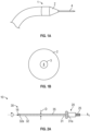
- some surgical dilators 1 may include a distal end in the form of a truncated cone 2 defining a lumen 3 therethrough for the passage of a guidewire 4.
- Such surgical dilators may display difficulty accurately accessing a target residing off-lumen or outside a given bodily lumen.
- such surgical dilators are designed to be simply forced or pushed through a tissue lumen wall which can lead to sudden and/or uncontrolled advances into unwanted tissues near the target and/or lumen.
- a dilator may accidently lurch forward after breaking through the wall. This sudden movement or lurching is not easy to prevent and may create potential risk to the patient by accidently puncturing a nearby blood vessel and/or producing a pneumothorax. This can cause usability and/or user confidence of these devices to be reduced and/or suffer.
- known dilators when particularly directed to navigating the various lumens of the lung, known dilators may be stiffer than the guide catheter and/or endoscope they are forced or pushed through to penetrate the lumen wall.
- a stiff surgical dilator may cause a straightening and/or misalignment of the guide catheter and/or endoscope during advancement and/or after alignment within the tissue has been established. This straightening may not only cause a misalignment with the target but may also account for the surgical dilator to advance at an oblique angle preventing proper tissue puncture or a glancing blow of the dilator.
- surgical dilators which can be more accurately controlled, require less force to advance through the lumen regardless of stiffness, and decrease the likelihood of misalignment during advancement.
- the present disclosure describes surgical dilators configured for passage through a natural lumen wall to an off-lumen target tissue or lesion.
- the surgical dilators may be configured to be rotated without causing the surgical dilator from becoming misaligned.
- the surgical dilators described herein may be configured to be advanced through tissue with or without rotation.
- the surgical dilators described herein includes a control handle operably coupled to an elongate tubular body.
- the tubular body extends between a proximal end portion and a distal end portion defining a dilator lumen extending from a proximal opening at the proximal end portion to a distal opening at the distal end portion.
- a tapered multi-faceted shaped tip extends between a base portion and a lead portion, the base portion connected to the distal end portion of the tubular body.
- the tip may include a tip lumen extending between a tip base opening and tip lead opening, the tip base open aligned and/or in fluid communication with dilator lumen, and particularly the distal opening of the dilator lumen.
- the control handle is positioned on the proximal end portion of the tubular body.
- the control handle may be configured to push and/or rotate the tubular body and the distal tip along and/or about a longitudinal axis thereof.
- One method includes positioning a surgical dilator through a lumen of a patient to a selected exit point in a wall of the lumen near the off-lumen lesion, the surgical dilator may be configured to be rotated and includes a multi-faceted shaped tip, rotating the surgical dilator and the multi-faceted tip, via the handle operably coupled thereto outside the patient, through the wall of the lumen; and creating and/or navigating a path beyond the lumen to the off-lumen lesion by rotating and/or advancing the surgical dilator outside beyond the lumen and in a direction towards the lesion.
- distal refers to the portion that is being described which is further from a user
- proximal refers to the portion that is being described which is closer to a user
- FIG. 2A depicts a surgical dilator 10 as provided herein.
- the surgical dilator 10 includes a control handle 20 (e.g., handle portion) operably coupled to a flexible elongate tubular body 30 (e.g., body portion).
- the elongate tubular body 30 extends between a proximal end portion 31 and a distal end portion 32.
- the proximal end portion 31, and/or particularly the proximal-most portion 31a is secured to a portion of the control handle 20.
- the distal end portion 32 and/or particularly the distal-most end 32a, has a multi-faceted shaped tip 16 extending distally therefrom.
- the tip 16 including a plurality of major and/or minor sides defining a plurality of major and/or minor cutting edges, shown in more detail in FIGS. 3A-11 .
- the control handle 20 is configured to rotate the entire tubular body 10, including the distal tip 16, about its longitudinal axis A 1 (as indicated by the arrow).
- the control handle 20 may be manually-operated or power operated.
- the control handle 20 may be directly operably coupled to the tubular body 30 or indirectly operably coupled to the tubular body via one or more coupling devices.
- the control handle 20 includes at least a rotatable grip 25 operably coupled to one or more gears 60, including but to limited to a planetary gear.
- a planetary gear 60 includes a central sun gear 61 surrounded by a plurality of planetary gears 62a-c held on a carrier 63 and enclosed within an outer gear ring 64.
- the grip 25 By rotating the grip 25 (see arrow), the one or more gears 60 are caused to rotate in a manner which causes the tubular body 30 to rotate about its longitudinal axis A 1 .
- the speed and/or torque associated with the spinning tubular body may be controlled by how the body, the handle and the gear are operably coupled. For example, as shown in FIG.
- the tubular body 30 may be coupled to the central sun gear 61 via either direct attachment or indirect attachment via a shaft coupler, overmold, or press-in coupler.
- the control handle 20 may be coupled to the outer gear 64 which is coupled to the central sun gear 61 via planetary gears 62a-c.
- Rotation of the rotatable grip 25 causes the outer gear 64 to rotate at a given speed, which further causes the other inner gears to rotate at a higher speed and potentially a lower torque than the outer gear 64.
- An increase in rotational speed and/or reduction in torque may be employed to achieve high relative displacement of the tip 16 in rotation relative to axial advancement without rotation thereby requiring less force on the tip 16 to advance through and/or cut through the tissue.
- the speed ratio of the outer gear 64 to the central sun gear 61 may be 1:2, 1:3, 1:5, 1:10, 1:20, 1:50, 1:100 and/or the torque ratio of the outer gear 64 to the central sun gear 61 may be 100:1, 50:1, 20:1, 10:1, 5:1, 3:1, 2:1.
- One example of such a gear may include a speeder gear box.
- the body 30 may be coupled to the outer gear 64 via either direct attachment or indirect attachment via a shaft coupler, overmold, or press-in coupler.
- the control handle 20 may be coupled to the central sun gear 61 which is coupled to the outer gear 64 via planetary gears 62a-c. Rotation of the rotatable grip 25 causes the central gear 61 to rotate at a given speed, which further causes the other outer gears to rotate at a lower speed and potentially a higher torque than the central sun gear 61.
- the speed ratio of the central sun gear 61 to the outer gear 64 may be 100:1, 50:1, 20:1, 10:1, 5:1, 3:1, 2:1 and/or the torque ratio of the central sun gear 61 to the outer gear 61 may be 1:2, 1:3, 1:5, 1:10, 1:20, 1:50, 1:100.
- the tubular body 30 generally defines one or more dilator lumens 35 extending from a proximal end portion 31 to a distal end portion 32 of the body 30.
- the tubular body may be made from any combination of suitable biocompatible materials.
- suitable biocompatible materials include polymeric materials, such as polycarbonates, polyamides, polyethylene, polypropylene, polystyrene, PEEK, and the like, and/or metals, such as stainless steel, gold, silver, platinum, tungsten, as well as shape memory materials such as nitinol.
- the tubular body 30 may maintain a constant diameter D (or thickness for non-circular embodiments) along the entire length of the tubular body 30, not necessarily including the tapered distal tip 16 and/or any proximal portion of the tubular body 31a directly coupled to the handle portion 20.
- the diameter D may range from about 0.02 to about 0.04 inches, and/or particularly, in some embodiments from about 0.025 to about 0.035 inches.
- Such a tubular body may further be configured to display a constant stiffness along the entire length of the body, again not necessarily including the distal tip and/or any proximal portion directly coupled to the handle portion.
- the tubular body may define a length ranging from about 10 cm to about 500 cm. In some embodiments, the length of the tubular body may be from about 20 cm to about 400 cm. In still other embodiments, the length of the tubular body may be from about 50 cm to about 300 cm. In still yet other embodiments, the length of the tubular body may be from about 125 cm to about 250 cm.
- the surgical dilator 110 includes a tubular body 112 configured for creating an off-lumen pathway to a target tissue, e.g., lesion.
- the pathway being subsequently used for the passage therethrough of one or more guidewires, guide catheters, and/or surgical instruments to treat, image, and/or biopsy the target tissue.
- FIGS. 3A-3C depict a surgical dilator 110 as provided in at least one embodiment herein.
- the surgical dilator 110 includes a tubular body 112 extending between a proximal end portion 112a and a distal end portion 112b.
- the dilator 110 may include a dilator lumen 114 extending from a proximal opening 114a at the proximal end portion 112a to a distal opening 114b at the distal end portion 112b.
- a tapered multi-faceted shaped tip 116 extends distally from the distal end portion 112b of the body 112.
- the tapered multi-faceted shaped tip 116 may include three or more facets, i.e., cutting edges 115. In some embodiments, the tapered multi-faceted shaped tip 116 may include three facets and/or cutting edges 115 to form a tapered tri-faceted shaped body.
- the tapered multi-faceted shaped tip 116 may also include a tip lumen 118 extending therethrough.
- the tip lumen 118 configured to longitudinally align with the distal opening 114b of the dilator lumen 114.
- the tip lumen 118 may taper from a proximal end portion 116a of the shaped tip 116 to the distal end portion 116b of the shaped tip 116.
- FIGS. 4A-4C also depict a surgical dilator 110 as provided in at least one embodiment herein.
- the surgical dilator 110 includes a tubular body 112 extending between a proximal end portion 112a and a distal end portion 112b.
- the dilator 110 may include a dilator lumen 114 extending from a proximal opening 114a at the proximal end portion 112a to a distal opening 114b at the distal end portion 112b.
- a tapered multi-faceted shaped tip 116 extends distally from the distal end portion 112b of the body 112.
- the tapered multi-faceted shaped tip 116 may include four or more facets and/or cutting edges 115. In some embodiments, the tapered multi-faceted shaped tip 116 may include four facets and/or cutting edges 115 to form a tapered tetra-faceted shaped body.
- the multi-faceted shaped tip 116 may also include a tip lumen 118 extending therethrough.
- the tip lumen 118 configured to longitudinally align with the distal opening 114b of the dilator lumen 114.
- the tip lumen 118 may maintain a constant diameter and/or may not taper from a proximal end portion 116a of the shaped tip 116 to the distal end portion 116b of the shaped tip 116.
- the tip lumen 118 configured to receive, maintain, and/or pass a guidewire, guide catheter, and/or a surgical instrument therethrough.
- the tapered multi-faceted shaped tip 216 may not include a tip lumen. It is envisioned that in some embodiments the addition of the multiple facets 215, i.e., cutting edges, allows the surgical dilator catheter to independently pierce a tissue wall without the preliminary assistance of a guidewire.
- the distal tip may be configured to be pierced with one or more guidewires, guide catheters, and/or surgical instruments for passage therethrough or the distal tip may be removably fixed to the distal end portion of the tubular body to allow for the passage of the one or more guidewires, guide catheters, and/or surgical instruments therethrough.
- FIGS. 6A-11B depict additional various non-limiting single-prong or multi-prong configurations of suitable tapered multi-faceted shaped tips.
- FIGS. 6A-8 depict various multi-faceted shaped tips defining a multi-prong configuration, and/or particularly a two-prong configuration
- FIGS. 9A-11B depict various multi-faceted shaped tips defining a single-prong configuration.
- the various depicted tapered multi-faceted shaped tips each include one or more major sides, minor sides, major cutting edges, minor cutting edges, and/or lead cutting edges.
- the major sides extend at least a predominant length of the shaped tip, while the minor sides extend less than a predominant length of the shaped tip.
- the minor sides are configured to be positioned between portions of two or more major sides, particularly between the lead part of two or more major sides.
- the major sides are larger in surface area than the minor sides, individually and/or collectively.
- the major cutting edges are located between neighboring major sides, while minor cutting edges are located between neighboring major and minor sides.
- a tapered multi-faceted tip 316 as described herein may include a base portion 317, a lead portion 317, at least a first and second major sides 322, 326, and at least a first and second outer minor sides 332, 336.
- the first major side 322 may extend between a first major base part 323 and a first major lead part 324.
- the first major base part 323 may be connected to a first part 317a of the base portion 317 of the tip 316 along a first major base cutting edge 351.
- the first major lead part 324 may include a first generally u-shaped lead part 324b positioned between a first outer lead part 324a and a second outer lead part 324c.
- the second major side 326 may extend between a second major base part 327 and a second major lead part 328.
- the second major base part 327 may be connected to a second part 317b of the base portion 317 of the tip 316 along a second major base cutting edge 353.
- the second major lead part 328 may include a second generally u-shaped lead part 328b positioned between a third outer lead part 328a and a fourth outer lead part 328c.
- the first outer minor side 332 may extend between a first minor base part 333 and a first minor lead part 324.
- the first minor base part 333 may be connected to a third part 317c of the base portion 317 of the tip 316 along a first outer minor base cutting edge 355.
- the second outer minor side 336 may extend between a second minor base part 337 and a second minor lead part 338, the second minor base part 337 connected to a fourth part 317d of the base portion 317 of the tip 316 along a second outer minor base cutting edge 357.
- first outer minor side 332 narrows distally from the first minor base part 333 to the first minor lead part 334 and/or the second outer minor side 336 narrows distally from the second minor base part 337 to the second minor lead part 338.
- first and third outer lead parts 324a, 328a of the first and second major sides 322, 326 may be further connected to the first outer minor side 332 along a first and second outer minor cutting edge 342, 344, respectively, and the second and fourth outer lead parts 324c, 328c connected to the second outer minor side 336 along a third and fourth outer minor cutting edge 346, 348, respectively.
- the first part 317a of the base portion 317 and the second part 317b of the base portion 317 are positioned on opposite sides of the base portion 317, and the third part 317c of the base portion 317 and the fourth 317d part of the base portion 317 are positioned on opposite sides of the base portion 317 different from the first and second parts 317a, 317b, wherein the first and second parts 317a, 317b of the base portion 317 may be proximal the third and fourth parts 317c, 317d of the base portion 317.
- the base portion 317 may be a rounded (e.g., circular, or elliptical) base portion from which one or more, if not all, the major sides 322, 326 and/or minor sides 332, 336 extend from.
- the rounded base portion 317 extends distally from a base portion edge 315 to the first and second major base cutting edges 351, 353 and the first and second minor base cutting edges 355, 357.
- the multi-faceted tip 316 as described herein may further include a curved or u-shaped inner minor side 339, and/or one or more lead faces 360, 365.
- the curved or u-shaped minor inner side 339 may connect the first and second u-shaped major lead parts 324b, 328b along first and second curved inner minor cutting edges 341, 343, respectively.
- the first lead face 360 may be connected to the first outer minor lead part 334 along a first outer minor lead cutting edge 361.
- the first lead face 360 may also be connected to a first end 339a of the curved or u-shaped minor inner side 339 along a first inner minor lead cutting edge 363.
- the first lead face 360 may further be connected to the first and third outer lead parts 324a, 328a along first and second major lead cutting edges 362, 364, respectively.
- the second lead face 365 may be connected to the second outer minor lead part 338 along a second outer minor lead cutting edge 366. In such embodiments, the second lead face 365 may also be connected to a second end 339b of the curved or u-shaped minor inner side 339 along a second inner minor lead cutting edge 368. In such embodiment, the second lead face 365 may further be connected to the second and fourth outer lead parts 324c, 328c along first and second major lead cutting edges 367, 369.
- At least one of the first lead face 360 and/or the second lead face 365 is a blunt, planar, and/or non-pointed face defined by four cutting edges, e.g., two opposing minor leading cutting edges 361, 363, 366, 368 and two opposing major leading cutting edges 362, 364, 367, 369.
- the first and second lead faces 360, 365 extend generally perpendicular to a longitudinal axis of the tip 316.
- At least one, if not both, of the first and second major sides 322, 326 may be generally planar as the tip 316 narrows distally from the base portion 317. In some embodiments, at least one, if not both, of the first and second major sides 322, 326 may be concave as the tip 316 narrows distally from the base portion 317.
- At least one, if not both, of the first and second outer minor sides 332, 336 may be generally planar as the minor sides 332, 336 narrow distally from the base portion 317. In some embodiments, at least one, if not both, of the first and second outer minor sides 332, 336 may be generally convex as the minor sides 332, 336 narrow distally from the base portion 317.
- FIGS. 7 and 8 depict alternative embodiments of the multi-prong e.g., two-prong, configuration of FIGS. 6A-6C , wherein the shaped tip 316 further includes a tip lumen 318 extending longitudinally therethrough.
- the shaped tip 316 further includes a tip lumen 318 extending longitudinally therethrough.
- the multi-faceted shaped tip 316 of a surgical dilator may include the first and second opposing major sides 322, 326 positioned between the first and second opposing outer minor sides 332, 336, a generally u-shaped inner minor side 339 positioned between the first and second lead faces 360, 365, and each of the cutting edges associated therewith as described herein, wherein a tip lumen 318 is positioned, and/or generally centered, between the two lead faces 360, 365, and positioned through a base part of the u-shaped inner wall 339.
- the tip lumen 318 is defined through a portion of the curved inner minor side 339 located between each prong of the two-prong configuration and set-back proximally from the lead face 360, 365 of each prong of the two-prong configuration.
- the multi-faceted shaped tip 316 of a surgical dilator includes the first and second opposing major sides 322, 326 positioned between the first and second opposing outer minor sides 332, 336, and each of the cutting edges associated therewith as described herein, wherein the tip lumen 318 replaces at least one of the curved or u-shaped inner minor side, the first lead face, and/or the second lead face.
- the various depicted tapered multi-faceted shaped tips may form a single prong configuration each including one or more major sides, minor sides, lead faces, major cutting edges, minor cutting edges, and/or lead cutting edges.
- the multi-faceted shaped tip 416 may form only a single prong configuration including a plurality of major sides 421, 422, 423, and 424 extending distally from a base portion 417 of the tip 416, a plurality of minor sides 431, 432, 433, and 434 positioned between a leading part 421b, 422b, 423b, and 424b of each of the major sides 421, 422, 423, and 424, a blunt lead face 460, a plurality of major, minor, and leading cutting edges 429-432, 446-453, 461-468, respectively, and a tip lumen 418 extending therethrough.
- leading parts 421b, 422b, 423b, and 424b of the plurality of major sides 421, 422, 423, and 424 alternate with the plurality of minor sides 431, 432, 433, and 434 around the lead portion 417 of the tip 416 forming alternating major leading cutting edges 461, 463, 465, 467 and minor leading cutting edges 462, 464, 466, 468, around the lead face 460.
- the plurality of minor sides 431, 432, 433, and 434 do not extend from the base portion 417 and/or are separated from the base portion 417 by the major sides 421, 422, 423, and 424.
- the plurality of major sides may include at least a first, second, third, and fourth major side 421, 422, 423, and 424 wrapped circumferentially around the tip 416.
- Each of the four major sides 421, 422, 423, and 424 angle distally to collectively narrow the tip 416.
- the first, second, third, and fourth major sides 421, 422, 423, and 424 may also be connected to each other via first, second, third, and fourth major cutting edges 429, 430, 431, and 432.
- first and second major sides 421, 422 are connected to each other along the first major cutting edge 429
- the second and third major sides 422, 423 are connected to each other along the second major cutting edge 430
- the third and fourth major sides 423, 424 are connected to each other along the third major cutting edge 431
- the fourth and first major sides 424, 421 are connected to each other along the fourth major cutting edge 432.
- the first, second, third, and fourth major cutting edges 429, 430, 431, and 432 may be distal to the major base cutting edges 425a-c, 426a-c, 427a-c, and 428a-c.
- a tapered multi-faceted tip 416 as described herein may extend between a base portion 417 and a lead portion 419, the tip 416 further including a lead face 460, a plurality of major sides (e.g., a first major side 421, a second major side 422, a third major side 423, and/or fourth major side 424), a plurality of minor sides (e.g., a first minor side 431, a second minor side 432, a third minor side 433, and/or fourth minor side 434), and a plurality of major, minor, and leading cutting edges 429-432, 446-453, 461-468, respectively.
- major sides e.g., a first major side 421, a second major side 422, a third major side 423, and/or fourth major side 42
- minor sides e.g., a first minor side 431, a second minor side 432, a third minor side 433, and/or fourth minor side 434
- the tip 416 may include at least three, if not 4 or more, first major sides.
- a first major side 421 may extend between a first major base part 421a and a first major lead part 421b, the first major base part 421a connected to a first part 417a of the base portion 417 of the tip 416 along one or more first major base cutting edges 425a-c and the first major lead part 421b connected to the lead face 460 along a first major lead cutting edge 461.
- a second major side 422 may extend between a second major base part 422a and a second major lead part 422b, the second major base part 422a connected to a second part 417b of the base portion 417 of the tip 416 along one or more second major base cutting edges 426a-c and the second major lead part 422b connected to the lead face 460 along a second major lead cutting edge 463, the second major side 422 connected to the first major side 421 along a first major cutting edge 429 extending between the second major base part 422a and the second major lead part 422b.
- a third major side 423 may extend between a third major base part 423a and a third major lead part 423b, the third major base part 423a connected to a third part 417c of the base portion 417 of the tip 416 along one or more third major base cutting edges 427a-c and the third major lead part 423b connected to the lead face 460 along a third major lead cutting edge 465, the third major side 423 connected to the second major side 422 along a second major cutting edge 430 extending between the third major base part 423a and the third major lead part 423b.
- a fourth major side 424 may extend between a fourth major base part 424a and a fourth major lead part 424b, the fourth major base part 424a connected to a fourth part 417d of the base portion 417 of the tip 416 along one or more fourth major base cutting edges 428a-c and the fourth major lead part 424b connected to the lead face 460 along a fourth major lead cutting edge 467, the fourth major side 424 connected to the third major side 423 along a third major cutting edge 438 extending between the fourth major base part 424a and the fourth major lead part 424b.
- the first major side 421 may further be connected to the fourth major side 424 along a fourth major cutting edge 439 extending between the first major base part 421a and the first major lead part 421b.
- the tip 416 may include at least three, if not 4 or more, first minor sides.
- a first minor side 431 may extend between a first minor base part 431a and a first minor lead part 431b, the first minor lead part 431b connected to the lead face 460 along a first minor lead cutting edge 462, the first minor side 431 connected to both the major lead part 421b of the first major side 421 along a first minor cutting edge 446 and the major lead part 422b of a second major side 422 along a second minor cutting edge 447.
- a second minor side 432 may extend between a second minor base part 432a and a second minor lead part 432b, the second minor lead part 432b connected to the lead face 460 along a second minor lead cutting edge 464, the second minor side 432 connected to both the major lead part 422b of the second major side 422 along a third minor cutting edge 448 and the major lead part 423b of the third major side 423 along a fourth minor cutting edge 449.
- a third minor side 433 extending between a third minor base part 433a and a third minor lead part 433b, the third minor lead part 433b connected to the lead face 460 along a third minor lead cutting edge 466 , the third minor side 433 connected to both the major lead part 423b of the third major side 423 along a fifth minor cutting edge 450 and the major lead part 424b of the fourth major side 424 along a sixth minor cutting edge 451.
- a fourth minor side 434 extending between a fourth minor base part 434a and a fourth minor lead part 434b, the fourth minor lead part 434b connected to the lead face 460 along a fourth minor lead cutting edge 468, the fourth minor side 434 connected to both the major lead part 424b of the fourth major side 424 along a seventh minor cutting edge 452 and the major lead part 421b of the first major side 421 along a eighth minor cutting edge 453.
- one or more, if not all, of the plurality of minor sides may widen distally towards the lead face 460.
- Some specific examples include the first minor side 431 widens distally from the first minor base part 431a to the first minor lead part 431b, the second outer minor side 432 widens distally from the second minor base part 432a to the second minor lead part 432b, the third outer minor side 433 widens distally from the third minor base part 433a to the third minor lead part 433b, and/or the fourth outer minor side 434 widens distally from the fourth minor base part 434a to the fourth minor lead part 434b.
- one or more, if not all, of the minor cutting edges 446-453 extend distally from one of the four major cutting edges 429, 430, 438, 439.
- Some specific examples include the first and second minor cutting edges 446, 447 extend distally from the first major cutting edge 429, the third and fourth minor cutting edges 448, 449 extend distally from the second major cutting edge 430, the fifth and sixth minor cutting edges 450, 451 extend distally from the third major cutting edge 438 and the seventh and eighth minor cutting edges 452, 453 extend distally from the fourth major cutting edge 439.
- the multi-faceted tip 416 may further include a tip lumen 418 positioned and/or passing through the lead face 460.
- FIG. 10 depicts an alternative embodiment of the single prong configuration of FIGS. 9A-9C , wherein the shaped tip 416 is covered by the blunt lead face 460 which is free of a tip lumen.
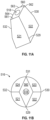
- FIGS. 11A and 11B depict another alternative embodiment of the single prong configuration, wherein a multi-faceted shaped tip 516 includes only a plurality of major sides 521, 522, 523, and 524 connected to each other via a plurality of major cutting edges 529, 530, 531, and 532, and further connected on a leading part thereof to a blunt lead face 560 along major leading cutting edges 561, 563, 565, and 567.
- a tip lumen 518 may also optionally extend therethrough.
- the blunt lead face 560 defines a diamond shape.
- the multi-faceted tip 516 may be free of minor sides and/or minor cutting edges.
- the distal end portion of the dilator and the tapered multifaceted shaped tip may be a monolithic structure.
- the distal end portion of the dilator and the tapered multifaceted shaped tip may be formed together using any suitable process including but not limited to one or more of extrusion, molding, casting, and/or pressing.
- the distal end portion of the dilator and the tapered multi-faceted shaped tip may be at least two separate pieces combined together to form the dilator.
- the distal end portion of the dilator and the tapered multifaceted shaped tip may be formed separately using any suitable process including but not limited to extrusion, molding, casting, pressing, and combinations thereof.
- the separate pieces may be combined to form the dilator using any suitable method including but not limited to one or more of coextrusion, over-molding, swaging, crimping, pressing, adhesives, threads, and/or male/female connectors.
- the handle 120 may be a power-operated control handle configured to rotate the tubular body 130 (and the distal tip associated therewith) of the surgical dilator.
- Control handle 120 includes a housing 121 configured to secure at least a motor 125 therein.
- the motor 125 operably coupled to the proximal end portion 131 of the tubular body 130 either directly or via a coupler 126.
- the motor 125 may be operably coupled to a planetary gear 160 which is operably coupled to the proximal end portion of the tubular body 131.
- the housing 121 may define at least one exterior channel 127 sized and dimensioned to receive actuator 128 configured to slide within the channel 127 to control and/or change the speed at which the body is rotated.
- a second actuator (not shown) may be configured to further control the amount of torque applied to the tubular body or steer the distal end portion and/or tip of the surgical dilator.
- a surgical dilator 210 as described herein may alternatively include a manually operated handle 220 affixed to a proximal end portion 212a of a tubular body 212 with a tapered multi-faceted tip 230 affixed to a distal end portion 212b of the body 212.
- the handle 220 may include a handle lumen 205 extending longitudinally therethrough and connecting to dilator lumen 235 extending through the body 212.
- the dilator lumen 235 may further connect to a tip lumen 218 extending through the tip 230.
- the handle 220 may include one or more grip members 225, such as grooves, bumps, etc.
- the handle 220 may be a knurled knob. The handle 220 being configured to manually steer and/or rotate the dilator 210.
- the surgical dilators described herein may be utilized to reach a desired target tissue and/or lesion located off-lumen.
- the surgical dilator may be designed to: navigate through a given lumen to a given point near the target tissue or lesion; exit the lumen via an exit point created in the lumen wall by advancing and/or rotating the surgical dilator through the lumen wall; and creating a path beyond the lumen to the target or lesion by continuing to advance and/or rotate the surgical dilator in the direction of the target or lesion.
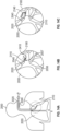
- a method for surgical dilator deployment to an off-lumen lesion includes: positioning and/or navigating a surgical dilator as described herein through a lumen of a patient, and particularly a lumen in the lungs, to a selected exit point in a wall of the lumen near the off-lumen lesion (FIG. 13A); advancing and/or rotating the surgical dilator, via the handle operably coupled thereto outside the patient, including the multi-faceted shaped tip, through the wall of the lumen (FIG. 13B); and creating a path beyond the lumen to the off-lumen lesion by rotating and/or advancing the surgical dilator outside the lumen and in a direction towards the lesion (FIG. 13C). Withdrawal of the surgical dilator may also occur.
- the rotation of the surgical dilator may be manually performed. In some embodiments, the rotation of the surgical dilator may be automatically performed by a power-operated handle or device.
- FIG. 14A illustrates a bronchoscope 2020, a catheter 2040 and a surgical dilator 2110 as described herein inserted into the lungs 2050 via a natural orifice (e.g., the mouth) of a patient 2150 toward an off-lumen target or lesion 2180 following a pathway plan.
- the proximal ends, i.e., handles, of the bronchoscope 2020 and catheter 2040 are not shown for clarity purposes.
- the bronchoscope 2020 When the bronchoscope 2020 reaches a certain location of the lung 2055, the bronchoscope 2020 becomes wedged and cannot go further into bronchial tree due to the size constraints.
- the catheter 2040 may be used to navigate the luminal network towards an off-lumen target 2180.
- the endoscope 2020, the catheter 2040 and/or the surgical dilator 2110 may follow a predetermined pathway plan associated and/developed using any known lung navigation software, e.g., the ILOGIC ® planning suite software currently sold by Covidien LP.
- FIG. 14B illustrates an enlarged detail view of the circled area of FIG. 14A , where the surgical dilator 2110, and particularly the distal multi-faceted tip 2140 of the surgical dilator (including any combination of configurations, sides, and/or cutting edges described herein), is advanced and/or rotated (see arrows) via the handle 2120 operably coupled thereto, through the wall 2057 of the lumen 2056 exiting the natural lumen 2056 of the lung 2055. Since the speed and/or torque of the rotation of the dilator 2110 may be controlled by the handles 2120, less force or push is required to advance the dilator 2110 through the lumen wall 2057. In addition, the stiffness of the dilator may remain stiffer than the catheter 2040 without causing the catheter to straighten or shift in position to become misaligned.
- the dilator and/or the multi-faceted tip may be rotated at a speed ranging from about 25 to about 2500 rpms In some other embodiments, the dilator and/or the multi-faceted tip may be rotated at a speed ranging from about 50 to about 1250 rpms In still other embodiments, the dilator and/or the multi-faceted tip may be rotated at a speed ranging from about 100 to about 1000 rpms.
- FIG. 14C illustrates the surgical dilator 2110, and particularly the multi-faceted tip 2140 of the surgical dilator 2110, continuing to be rotated while advancing (see arrows) creating an off-lumen path beyond the wall 2057 and/or exit point of the lumen 2056 and in the direction of the off-lumen lesion 2180.
- the path being created by the rotating and/or advancing the surgical dilator 2110 outside of the lumen 2056 and in a direction towards the lesion 2180.
- the surgical dilator 2110 ultimately butting up against the target tissue or lesion 2180.
- the catheter 2040 may be extended over the surgical dilator 2110 to maintain the patency of the path and/or the surgical dilator 2110 may be withdrawn and replaced with any suitable surgical instrument to treat, resect, and/or biopsy the off-lumen tissue or lesion 2180.
Landscapes
- Health & Medical Sciences (AREA)
- Life Sciences & Earth Sciences (AREA)
- Public Health (AREA)
- Veterinary Medicine (AREA)
- Engineering & Computer Science (AREA)
- Biomedical Technology (AREA)
- Heart & Thoracic Surgery (AREA)
- General Health & Medical Sciences (AREA)
- Animal Behavior & Ethology (AREA)
- Surgery (AREA)
- Hematology (AREA)
- Anesthesiology (AREA)
- Biophysics (AREA)
- Medical Informatics (AREA)
- Molecular Biology (AREA)
- Nuclear Medicine, Radiotherapy & Molecular Imaging (AREA)
- Pulmonology (AREA)
- Pathology (AREA)
- Orthopedic Medicine & Surgery (AREA)
- Physics & Mathematics (AREA)
- Optics & Photonics (AREA)
- Radiology & Medical Imaging (AREA)
- Surgical Instruments (AREA)
- Media Introduction/Drainage Providing Device (AREA)
Abstract
Description
- The present technology is generally related to surgical dilators, and more particularly, surgical dilators designed for accessing targets located beyond a defined luminal body structure and including enhanced cutting characteristics.
- A variety of surgical dilators have been developed. Of these known devices, each has certain advantages and disadvantages. However, there is an ongoing need to provide alternative surgical dilators and methods of using such surgical dilators. For example, as shown in
FIGS. 1A and 1B , some surgical dilators 1 may include a distal end in the form of a truncatedcone 2 defining alumen 3 therethrough for the passage of aguidewire 4. Such surgical dilators may display difficulty accurately accessing a target residing off-lumen or outside a given bodily lumen. Particularly, such surgical dilators are designed to be simply forced or pushed through a tissue lumen wall which can lead to sudden and/or uncontrolled advances into unwanted tissues near the target and/or lumen. For example, in an effort to overcome the viscoelastic forces associated with the wall tissue, a dilator may accidently lurch forward after breaking through the wall. This sudden movement or lurching is not easy to prevent and may create potential risk to the patient by accidently puncturing a nearby blood vessel and/or producing a pneumothorax. This can cause usability and/or user confidence of these devices to be reduced and/or suffer. - In addition, when particularly directed to navigating the various lumens of the lung, known dilators may be stiffer than the guide catheter and/or endoscope they are forced or pushed through to penetrate the lumen wall. A stiff surgical dilator may cause a straightening and/or misalignment of the guide catheter and/or endoscope during advancement and/or after alignment within the tissue has been established. This straightening may not only cause a misalignment with the target but may also account for the surgical dilator to advance at an oblique angle preventing proper tissue puncture or a glancing blow of the dilator. Thus, there exists a need to provide surgical dilators which can be more accurately controlled, require less force to advance through the lumen regardless of stiffness, and decrease the likelihood of misalignment during advancement.
- The present disclosure describes surgical dilators configured for passage through a natural lumen wall to an off-lumen target tissue or lesion. The surgical dilators may be configured to be rotated without causing the surgical dilator from becoming misaligned. However, the surgical dilators described herein may be configured to be advanced through tissue with or without rotation.
- The surgical dilators described herein includes a control handle operably coupled to an elongate tubular body. The tubular body extends between a proximal end portion and a distal end portion defining a dilator lumen extending from a proximal opening at the proximal end portion to a distal opening at the distal end portion. A tapered multi-faceted shaped tip extends between a base portion and a lead portion, the base portion connected to the distal end portion of the tubular body. The tip may include a tip lumen extending between a tip base opening and tip lead opening, the tip base open aligned and/or in fluid communication with dilator lumen, and particularly the distal opening of the dilator lumen. The control handle is positioned on the proximal end portion of the tubular body. The control handle may be configured to push and/or rotate the tubular body and the distal tip along and/or about a longitudinal axis thereof.
- Methods for deploying the surgical dilators to an off-lumen lesion are also provided. One method includes positioning a surgical dilator through a lumen of a patient to a selected exit point in a wall of the lumen near the off-lumen lesion, the surgical dilator may be configured to be rotated and includes a multi-faceted shaped tip, rotating the surgical dilator and the multi-faceted tip, via the handle operably coupled thereto outside the patient, through the wall of the lumen; and creating and/or navigating a path beyond the lumen to the off-lumen lesion by rotating and/or advancing the surgical dilator outside beyond the lumen and in a direction towards the lesion.
- Various aspects and features of the present disclosure are described herein below with reference to the drawings, wherein:
-
FIGS. 1A and 1B depict a side view and front end view, respectively, of a known surgical dilator; -
FIG. 2A depicts a side view of a surgical dilator as described in at least one embodiment herein; -
FIG. 2B depicts a schematic perspective view of a handle portion of the surgical dilator ofFIG. 2A as described in at least one embodiment herein -
FIGS. 3A and3B depict a side view and front end view, respectively, of a surgical dilator as described in at least one embodiment herein; -
FIG. 3C depicts a cross-sectional view of the surgical dilator ofFIG. 3A as described in at least one embodiment herein; -
FIGS. 4A and4B depict a side view and front end view, respectively, of a surgical dilator as described in at least one embodiment herein; -
FIG. 4C depicts a cross-sectional view of the surgical dilator ofFIG. 4A as described in at least one embodiment herein; -
FIG. 5 depicts a front end view of a surgical dilator as described in at least one embodiment herein; -
FIGS. 6A ,6B , and6C depict a left perspective side view, a right perspective view, and top view, respectively, of a multi-faceted shaped body of a surgical dilator as described in at least one embodiment herein; -
FIGS. 7 and 8 depict a top view of a multi-faceted shaped body of a surgical dilator as described in at least one embodiment herein; -
FIGS. 9A ,9B , and9C depict a left perspective side view, a right perspective view, and top view, respectively, of a multi-faceted shaped body of a surgical dilator as described in at least one embodiment herein; -
FIG. 10 depicts a top view of a multi-faceted shaped body of a surgical dilator as described in at least one embodiment herein; -
FIGS. 11A and 11B depict a perspective side view and top view, respectively, of a multi-faceted shaped body of a surgical dilator as described in at least one embodiment herein; -
FIG. 12 depicts a schematic perspective view of a handle portion of a surgical dilator as described in at least one embodiment herein; -
FIG. 13 depicts a side view of a surgical dilator as described in at least one embodiment herein; -
FIG. 14A is an illustration of a dilator assembly including a surgical dilator inserted into a lung as described in at least one embodiment herein; and -
FIGS. 14B and 14C are enlarged detail views of the circled area ofFIG. 14A . - Detailed embodiments of the present disclosure are disclosed herein; however, the disclosed embodiments are merely examples of the disclosure, which may be embodied in various forms. Therefore, specific structural and functional details disclosed herein are not to be interpreted as limiting, but merely as a basis for the claims and as a representative basis for teaching one skilled in the art to variously employ the present disclosure in virtually any appropriately detailed structure.
- Aspects of the present disclosure are described in detail with reference to the drawing figures wherein like reference numerals identify similar or identical elements. As used herein, the term "distal" refers to the portion that is being described which is further from a user, while the term "proximal" refers to the portion that is being described which is closer to a user.
- The present disclosure is directed in part to a surgical dilator catheters configured for improved off-lumen deployment.
FIG. 2A depicts asurgical dilator 10 as provided herein. Thesurgical dilator 10 includes a control handle 20 (e.g., handle portion) operably coupled to a flexible elongate tubular body 30 (e.g., body portion). The elongatetubular body 30 extends between aproximal end portion 31 and adistal end portion 32. Theproximal end portion 31, and/or particularly theproximal-most portion 31a, is secured to a portion of the control handle 20. Thedistal end portion 32, and/or particularly thedistal-most end 32a, has a multi-faceted shapedtip 16 extending distally therefrom. Thetip 16 including a plurality of major and/or minor sides defining a plurality of major and/or minor cutting edges, shown in more detail inFIGS. 3A-11 . - The control handle 20 is configured to rotate the entire
tubular body 10, including thedistal tip 16, about its longitudinal axis A1 (as indicated by the arrow). The control handle 20 may be manually-operated or power operated. The control handle 20 may be directly operably coupled to thetubular body 30 or indirectly operably coupled to the tubular body via one or more coupling devices. - As shown in
FIG. 2B , in some embodiments, the control handle 20 includes at least arotatable grip 25 operably coupled to one ormore gears 60, including but to limited to a planetary gear. Aplanetary gear 60 includes acentral sun gear 61 surrounded by a plurality ofplanetary gears 62a-c held on acarrier 63 and enclosed within anouter gear ring 64. By rotating the grip 25 (see arrow), the one ormore gears 60 are caused to rotate in a manner which causes thetubular body 30 to rotate about its longitudinal axis A1. The speed and/or torque associated with the spinning tubular body may be controlled by how the body, the handle and the gear are operably coupled. For example, as shown inFIG. 2B , in some embodiments, thetubular body 30 may be coupled to thecentral sun gear 61 via either direct attachment or indirect attachment via a shaft coupler, overmold, or press-in coupler. In such embodiments, the control handle 20 may be coupled to theouter gear 64 which is coupled to thecentral sun gear 61 viaplanetary gears 62a-c. Rotation of therotatable grip 25 causes theouter gear 64 to rotate at a given speed, which further causes the other inner gears to rotate at a higher speed and potentially a lower torque than theouter gear 64. An increase in rotational speed and/or reduction in torque may be employed to achieve high relative displacement of thetip 16 in rotation relative to axial advancement without rotation thereby requiring less force on thetip 16 to advance through and/or cut through the tissue. In some embodiments, the speed ratio of theouter gear 64 to thecentral sun gear 61 may be 1:2, 1:3, 1:5, 1:10, 1:20, 1:50, 1:100 and/or the torque ratio of theouter gear 64 to thecentral sun gear 61 may be 100:1, 50:1, 20:1, 10:1, 5:1, 3:1, 2:1. One example of such a gear may include a speeder gear box. - In still other embodiments, the
body 30 may be coupled to theouter gear 64 via either direct attachment or indirect attachment via a shaft coupler, overmold, or press-in coupler. In such embodiments, the control handle 20 may be coupled to thecentral sun gear 61 which is coupled to theouter gear 64 viaplanetary gears 62a-c. Rotation of therotatable grip 25 causes thecentral gear 61 to rotate at a given speed, which further causes the other outer gears to rotate at a lower speed and potentially a higher torque than thecentral sun gear 61. In some embodiments, the speed ratio of thecentral sun gear 61 to theouter gear 64 may be 100:1, 50:1, 20:1, 10:1, 5:1, 3:1, 2:1 and/or the torque ratio of thecentral sun gear 61 to theouter gear 61 may be 1:2, 1:3, 1:5, 1:10, 1:20, 1:50, 1:100. - The
tubular body 30 generally defines one ormore dilator lumens 35 extending from aproximal end portion 31 to adistal end portion 32 of thebody 30. The tubular body may be made from any combination of suitable biocompatible materials. Some non-limiting examples include polymeric materials, such as polycarbonates, polyamides, polyethylene, polypropylene, polystyrene, PEEK, and the like, and/or metals, such as stainless steel, gold, silver, platinum, tungsten, as well as shape memory materials such as nitinol. - As further depicted in
FIG. 2A , thetubular body 30 may maintain a constant diameter D (or thickness for non-circular embodiments) along the entire length of thetubular body 30, not necessarily including the tapereddistal tip 16 and/or any proximal portion of thetubular body 31a directly coupled to thehandle portion 20. The diameter D may range from about 0.02 to about 0.04 inches, and/or particularly, in some embodiments from about 0.025 to about 0.035 inches. Such a tubular body may further be configured to display a constant stiffness along the entire length of the body, again not necessarily including the distal tip and/or any proximal portion directly coupled to the handle portion. - The tubular body may define a length ranging from about 10 cm to about 500 cm. In some embodiments, the length of the tubular body may be from about 20 cm to about 400 cm. In still other embodiments, the length of the tubular body may be from about 50 cm to about 300 cm. In still yet other embodiments, the length of the tubular body may be from about 125 cm to about 250 cm.
- Turning to
FIGS. 3A-3C , thesurgical dilator 110 includes atubular body 112 configured for creating an off-lumen pathway to a target tissue, e.g., lesion. The pathway being subsequently used for the passage therethrough of one or more guidewires, guide catheters, and/or surgical instruments to treat, image, and/or biopsy the target tissue. -
FIGS. 3A-3C depict asurgical dilator 110 as provided in at least one embodiment herein. Thesurgical dilator 110 includes atubular body 112 extending between aproximal end portion 112a and adistal end portion 112b. Thedilator 110 may include adilator lumen 114 extending from aproximal opening 114a at theproximal end portion 112a to adistal opening 114b at thedistal end portion 112b. A tapered multi-faceted shapedtip 116 extends distally from thedistal end portion 112b of thebody 112. - As specifically depicted in
FIG. 3B , in some embodiments, the tapered multi-faceted shapedtip 116 may include three or more facets, i.e., cuttingedges 115. In some embodiments, the tapered multi-faceted shapedtip 116 may include three facets and/or cuttingedges 115 to form a tapered tri-faceted shaped body. - The tapered multi-faceted shaped
tip 116 may also include atip lumen 118 extending therethrough. Thetip lumen 118 configured to longitudinally align with thedistal opening 114b of thedilator lumen 114. In some embodiments, as depicted inFIG. 3C , thetip lumen 118 may taper from aproximal end portion 116a of the shapedtip 116 to thedistal end portion 116b of the shapedtip 116. -
FIGS. 4A-4C also depict asurgical dilator 110 as provided in at least one embodiment herein. Thesurgical dilator 110 includes atubular body 112 extending between aproximal end portion 112a and adistal end portion 112b. Thedilator 110 may include adilator lumen 114 extending from aproximal opening 114a at theproximal end portion 112a to adistal opening 114b at thedistal end portion 112b. A tapered multi-faceted shapedtip 116 extends distally from thedistal end portion 112b of thebody 112. - As specifically depicted in
FIG. 4B , in some embodiments, the tapered multi-faceted shapedtip 116 may include four or more facets and/or cuttingedges 115. In some embodiments, the tapered multi-faceted shapedtip 116 may include four facets and/or cuttingedges 115 to form a tapered tetra-faceted shaped body. - The multi-faceted shaped
tip 116 may also include atip lumen 118 extending therethrough. Thetip lumen 118 configured to longitudinally align with thedistal opening 114b of thedilator lumen 114. In some embodiments, as depicted inFIG. 4C , thetip lumen 118 may maintain a constant diameter and/or may not taper from aproximal end portion 116a of the shapedtip 116 to thedistal end portion 116b of the shapedtip 116. Thetip lumen 118 configured to receive, maintain, and/or pass a guidewire, guide catheter, and/or a surgical instrument therethrough. - In some embodiments, as shown in
FIG. 5 , the tapered multi-faceted shapedtip 216 may not include a tip lumen. It is envisioned that in some embodiments the addition of themultiple facets 215, i.e., cutting edges, allows the surgical dilator catheter to independently pierce a tissue wall without the preliminary assistance of a guidewire. In such embodiments, it is envisioned that the distal tip may be configured to be pierced with one or more guidewires, guide catheters, and/or surgical instruments for passage therethrough or the distal tip may be removably fixed to the distal end portion of the tubular body to allow for the passage of the one or more guidewires, guide catheters, and/or surgical instruments therethrough. -
FIGS. 6A-11B depict additional various non-limiting single-prong or multi-prong configurations of suitable tapered multi-faceted shaped tips. For example,FIGS. 6A-8 depict various multi-faceted shaped tips defining a multi-prong configuration, and/or particularly a two-prong configuration, whileFIGS. 9A-11B depict various multi-faceted shaped tips defining a single-prong configuration. - In
FIGS. 6A-8 , the various depicted tapered multi-faceted shaped tips each include one or more major sides, minor sides, major cutting edges, minor cutting edges, and/or lead cutting edges. The major sides extend at least a predominant length of the shaped tip, while the minor sides extend less than a predominant length of the shaped tip. The minor sides are configured to be positioned between portions of two or more major sides, particularly between the lead part of two or more major sides. The major sides are larger in surface area than the minor sides, individually and/or collectively. The major cutting edges are located between neighboring major sides, while minor cutting edges are located between neighboring major and minor sides. - As depicted in
FIGS. 6A-6C , in some embodiments of the multi-prong, e.g., two-prong, configuration, a taperedmulti-faceted tip 316 as described herein may include abase portion 317, alead portion 317, at least a first and secondmajor sides minor sides major side 322 may extend between a firstmajor base part 323 and a first majorlead part 324. The firstmajor base part 323 may be connected to afirst part 317a of thebase portion 317 of thetip 316 along a first majorbase cutting edge 351. The first majorlead part 324 may include a first generally u-shapedlead part 324b positioned between a firstouter lead part 324a and a second outerlead part 324c. - In such embodiments, the second
major side 326 may extend between a secondmajor base part 327 and a second majorlead part 328. The secondmajor base part 327 may be connected to asecond part 317b of thebase portion 317 of thetip 316 along a second majorbase cutting edge 353. The second majorlead part 328 may include a second generally u-shapedlead part 328b positioned between a third outerlead part 328a and a fourth outerlead part 328c. - In such embodiments, the first outer
minor side 332 may extend between a first minor base part 333 and a first minorlead part 324. The first minor base part 333 may be connected to athird part 317c of thebase portion 317 of thetip 316 along a first outer minorbase cutting edge 355. The second outerminor side 336 may extend between a secondminor base part 337 and a second minorlead part 338, the secondminor base part 337 connected to afourth part 317d of thebase portion 317 of thetip 316 along a second outer minorbase cutting edge 357. In some embodiments, the first outerminor side 332 narrows distally from the first minor base part 333 to the first minorlead part 334 and/or the second outerminor side 336 narrows distally from the secondminor base part 337 to the second minorlead part 338. - In such embodiments, the first and third
outer lead parts major sides minor side 332 along a first and second outerminor cutting edge lead parts minor side 336 along a third and fourth outerminor cutting edge first part 317a of thebase portion 317 and thesecond part 317b of thebase portion 317 are positioned on opposite sides of thebase portion 317, and thethird part 317c of thebase portion 317 and the fourth 317d part of thebase portion 317 are positioned on opposite sides of thebase portion 317 different from the first andsecond parts second parts base portion 317 may be proximal the third andfourth parts base portion 317. - In such embodiments, the
base portion 317 may be a rounded (e.g., circular, or elliptical) base portion from which one or more, if not all, themajor sides minor sides base portion 317 extends distally from abase portion edge 315 to the first and second majorbase cutting edges base cutting edges - As further depicted in
FIGS. 6A-6C , in some embodiments of the multi-prong, e.g., two-prong, configuration, themulti-faceted tip 316 as described herein may further include a curved or u-shaped innerminor side 339, and/or one or more lead faces 360, 365. In such embodiments, the curved or u-shaped minorinner side 339 may connect the first and second u-shaped majorlead parts minor cutting edges - In such embodiments, the first
lead face 360 may be connected to the first outer minorlead part 334 along a first outer minorlead cutting edge 361. In such embodiments, the firstlead face 360 may also be connected to afirst end 339a of the curved or u-shaped minorinner side 339 along a first inner minorlead cutting edge 363. In such embodiment, the firstlead face 360 may further be connected to the first and thirdouter lead parts lead cutting edges - In such embodiments, the second
lead face 365 may be connected to the second outer minorlead part 338 along a second outer minorlead cutting edge 366. In such embodiments, the secondlead face 365 may also be connected to asecond end 339b of the curved or u-shaped minorinner side 339 along a second inner minorlead cutting edge 368. In such embodiment, the secondlead face 365 may further be connected to the second and fourth outerlead parts lead cutting edges - In some embodiments, at least one of the first
lead face 360 and/or the secondlead face 365 is a blunt, planar, and/or non-pointed face defined by four cutting edges, e.g., two opposing minor leadingcutting edges cutting edges tip 316. - In some embodiments, at least one, if not both, of the first and second
major sides tip 316 narrows distally from thebase portion 317. In some embodiments, at least one, if not both, of the first and secondmajor sides tip 316 narrows distally from thebase portion 317. - In some embodiments, at least one, if not both, of the first and second outer
minor sides minor sides base portion 317. In some embodiments, at least one, if not both, of the first and second outerminor sides minor sides base portion 317. -
FIGS. 7 and 8 depict alternative embodiments of the multi-prong e.g., two-prong, configuration ofFIGS. 6A-6C , wherein the shapedtip 316 further includes atip lumen 318 extending longitudinally therethrough. For example, as shown inFIG. 7 , in some embodiments, the multi-faceted shapedtip 316 of a surgical dilator may include the first and second opposingmajor sides minor sides minor side 339 positioned between the first and second lead faces 360, 365, and each of the cutting edges associated therewith as described herein, wherein atip lumen 318 is positioned, and/or generally centered, between the two lead faces 360, 365, and positioned through a base part of the u-shapedinner wall 339. In such embodiments, thetip lumen 318 is defined through a portion of the curved innerminor side 339 located between each prong of the two-prong configuration and set-back proximally from thelead face - In another example, as shown in
FIG. 8 , in some embodiments, the multi-faceted shapedtip 316 of a surgical dilator includes the first and second opposingmajor sides minor sides tip lumen 318 replaces at least one of the curved or u-shaped inner minor side, the first lead face, and/or the second lead face. - Turning to
FIGS. 9A-11B , in some embodiments, the various depicted tapered multi-faceted shaped tips may form a single prong configuration each including one or more major sides, minor sides, lead faces, major cutting edges, minor cutting edges, and/or lead cutting edges. -
FIGS. 9A-9C , in some embodiments, the multi-faceted shapedtip 416 may form only a single prong configuration including a plurality ofmajor sides base portion 417 of thetip 416, a plurality ofminor sides leading part major sides blunt lead face 460, a plurality of major, minor, and leading cutting edges 429-432, 446-453, 461-468, respectively, and atip lumen 418 extending therethrough. In some embodiments, the leadingparts major sides minor sides lead portion 417 of thetip 416 forming alternating major leadingcutting edges leading cutting edges lead face 460. In some embodiments, the plurality ofminor sides base portion 417 and/or are separated from thebase portion 417 by themajor sides - In the single prong configuration of
FIGS. 9A-9C , the plurality of major sides may include at least a first, second, third, and fourthmajor side tip 416. Each of the fourmajor sides tip 416. The first, second, third, and fourthmajor sides major cutting edges major sides major cutting edge 429, the second and thirdmajor sides major cutting edge 430, the third and fourthmajor sides major cutting edge 431, and the fourth and firstmajor sides major cutting edge 432. The first, second, third, and fourthmajor cutting edges base cutting edges 425a-c, 426a-c, 427a-c, and 428a-c. - As depicted in
FIGS. 9A-9C , in some embodiments of a single-prong configuration, a taperedmulti-faceted tip 416 as described herein may extend between abase portion 417 and alead portion 419, thetip 416 further including alead face 460, a plurality of major sides (e.g., a firstmajor side 421, a secondmajor side 422, a thirdmajor side 423, and/or fourth major side 424), a plurality of minor sides (e.g., a firstminor side 431, a secondminor side 432, a thirdminor side 433, and/or fourth minor side 434), and a plurality of major, minor, and leading cutting edges 429-432, 446-453, 461-468, respectively. - In such embodiments, the
tip 416 may include at least three, if not 4 or more, first major sides. A firstmajor side 421 may extend between a firstmajor base part 421a and a first majorlead part 421b, the firstmajor base part 421a connected to afirst part 417a of thebase portion 417 of thetip 416 along one or more first majorbase cutting edges 425a-c and the first majorlead part 421b connected to thelead face 460 along a first majorlead cutting edge 461. A secondmajor side 422 may extend between a secondmajor base part 422a and a second majorlead part 422b, the secondmajor base part 422a connected to asecond part 417b of thebase portion 417 of thetip 416 along one or more second majorbase cutting edges 426a-c and the second majorlead part 422b connected to thelead face 460 along a second majorlead cutting edge 463, the secondmajor side 422 connected to the firstmajor side 421 along a firstmajor cutting edge 429 extending between the secondmajor base part 422a and the second majorlead part 422b. A thirdmajor side 423 may extend between a thirdmajor base part 423a and a third majorlead part 423b, the thirdmajor base part 423a connected to athird part 417c of thebase portion 417 of thetip 416 along one or more third majorbase cutting edges 427a-c and the third majorlead part 423b connected to thelead face 460 along a third majorlead cutting edge 465, the thirdmajor side 423 connected to the secondmajor side 422 along a secondmajor cutting edge 430 extending between the thirdmajor base part 423a and the third majorlead part 423b. A fourthmajor side 424 may extend between a fourthmajor base part 424a and a fourth majorlead part 424b, the fourthmajor base part 424a connected to afourth part 417d of thebase portion 417 of thetip 416 along one or more fourth majorbase cutting edges 428a-c and the fourth majorlead part 424b connected to thelead face 460 along a fourth majorlead cutting edge 467, the fourthmajor side 424 connected to the thirdmajor side 423 along a thirdmajor cutting edge 438 extending between the fourthmajor base part 424a and the fourth majorlead part 424b. The firstmajor side 421 may further be connected to the fourthmajor side 424 along a fourthmajor cutting edge 439 extending between the firstmajor base part 421a and the first majorlead part 421b. - Further, in such embodiments, the
tip 416 may include at least three, if not 4 or more, first minor sides. A firstminor side 431 may extend between a firstminor base part 431a and a first minorlead part 431b, the first minorlead part 431b connected to thelead face 460 along a first minorlead cutting edge 462, the firstminor side 431 connected to both the majorlead part 421b of the firstmajor side 421 along a firstminor cutting edge 446 and the majorlead part 422b of a secondmajor side 422 along a secondminor cutting edge 447. A secondminor side 432 may extend between a secondminor base part 432a and a second minorlead part 432b, the second minorlead part 432b connected to thelead face 460 along a second minorlead cutting edge 464, the secondminor side 432 connected to both the majorlead part 422b of the secondmajor side 422 along a thirdminor cutting edge 448 and the majorlead part 423b of the thirdmajor side 423 along a fourthminor cutting edge 449. A thirdminor side 433 extending between a thirdminor base part 433a and a third minorlead part 433b, the third minorlead part 433b connected to thelead face 460 along a third minorlead cutting edge 466 , the thirdminor side 433 connected to both the majorlead part 423b of the thirdmajor side 423 along a fifthminor cutting edge 450 and the majorlead part 424b of the fourthmajor side 424 along a sixthminor cutting edge 451. A fourthminor side 434 extending between a fourthminor base part 434a and a fourth minorlead part 434b, the fourth minorlead part 434b connected to thelead face 460 along a fourth minorlead cutting edge 468, the fourthminor side 434 connected to both the majorlead part 424b of the fourthmajor side 424 along a seventhminor cutting edge 452 and the majorlead part 421b of the firstmajor side 421 along a eighthminor cutting edge 453. - In some additional embodiments regarding a single prong configuration, one or more, if not all, of the plurality of minor sides (e.g., ., a first
minor side 431, a secondminor side 432, a thirdminor side 433, and/or fourth minor side 434) may widen distally towards thelead face 460. Some specific examples include the firstminor side 431 widens distally from the firstminor base part 431a to the first minorlead part 431b, the second outerminor side 432 widens distally from the secondminor base part 432a to the second minorlead part 432b, the third outerminor side 433 widens distally from the thirdminor base part 433a to the third minorlead part 433b, and/or the fourth outerminor side 434 widens distally from the fourthminor base part 434a to the fourth minorlead part 434b. - In some additional embodiments regarding a single prong configuration, one or more, if not all, of the minor cutting edges 446-453 extend distally from one of the four
major cutting edges minor cutting edges major cutting edge 429, the third and fourthminor cutting edges major cutting edge 430, the fifth and sixthminor cutting edges major cutting edge 438 and the seventh and eighthminor cutting edges major cutting edge 439. - In some additional embodiments regarding a single prong configuration, the
multi-faceted tip 416 may further include atip lumen 418 positioned and/or passing through thelead face 460. -
FIG. 10 depicts an alternative embodiment of the single prong configuration ofFIGS. 9A-9C , wherein the shapedtip 416 is covered by theblunt lead face 460 which is free of a tip lumen. -
FIGS. 11A and 11B depict another alternative embodiment of the single prong configuration, wherein a multi-faceted shapedtip 516 includes only a plurality ofmajor sides major cutting edges blunt lead face 560 along major leadingcutting edges 561, 563, 565, and 567. Atip lumen 518 may also optionally extend therethrough. In some embodiments, theblunt lead face 560 defines a diamond shape. In some embodiments, themulti-faceted tip 516 may be free of minor sides and/or minor cutting edges. - In some embodiments, the distal end portion of the dilator and the tapered multifaceted shaped tip may be a monolithic structure. In such embodiments, the distal end portion of the dilator and the tapered multifaceted shaped tip may be formed together using any suitable process including but not limited to one or more of extrusion, molding, casting, and/or pressing.
- In some embodiments, the distal end portion of the dilator and the tapered multi-faceted shaped tip may be at least two separate pieces combined together to form the dilator. In such embodiments, the distal end portion of the dilator and the tapered multifaceted shaped tip may be formed separately using any suitable process including but not limited to extrusion, molding, casting, pressing, and combinations thereof. The separate pieces may be combined to form the dilator using any suitable method including but not limited to one or more of coextrusion, over-molding, swaging, crimping, pressing, adhesives, threads, and/or male/female connectors.
- Turning to
FIG. 12 , in some embodiments, thehandle 120 may be a power-operated control handle configured to rotate the tubular body 130 (and the distal tip associated therewith) of the surgical dilator. Control handle 120 includes ahousing 121 configured to secure at least amotor 125 therein. Themotor 125 operably coupled to theproximal end portion 131 of thetubular body 130 either directly or via acoupler 126. In some embodiments, themotor 125 may be operably coupled to aplanetary gear 160 which is operably coupled to the proximal end portion of thetubular body 131. - As further shown in
FIG. 12 , thehousing 121 may define at least oneexterior channel 127 sized and dimensioned to receiveactuator 128 configured to slide within thechannel 127 to control and/or change the speed at which the body is rotated. In some embodiments, a second actuator (not shown) may be configured to further control the amount of torque applied to the tubular body or steer the distal end portion and/or tip of the surgical dilator. - Turning to
FIG. 13 , in some embodiments, asurgical dilator 210 as described herein may alternatively include a manually operatedhandle 220 affixed to aproximal end portion 212a of atubular body 212 with a taperedmulti-faceted tip 230 affixed to adistal end portion 212b of thebody 212. Thehandle 220 may include ahandle lumen 205 extending longitudinally therethrough and connecting todilator lumen 235 extending through thebody 212. Thedilator lumen 235 may further connect to atip lumen 218 extending through thetip 230. Thehandle 220 may include one ormore grip members 225, such as grooves, bumps, etc. In some embodiments, thehandle 220 may be a knurled knob. Thehandle 220 being configured to manually steer and/or rotate thedilator 210. - The surgical dilators described herein may be utilized to reach a desired target tissue and/or lesion located off-lumen. By the tissue or lesion being located off-lumen, the surgical dilator may be designed to: navigate through a given lumen to a given point near the target tissue or lesion; exit the lumen via an exit point created in the lumen wall by advancing and/or rotating the surgical dilator through the lumen wall; and creating a path beyond the lumen to the target or lesion by continuing to advance and/or rotate the surgical dilator in the direction of the target or lesion.
- In some embodiments, a method for surgical dilator deployment to an off-lumen lesion includes: positioning and/or navigating a surgical dilator as described herein through a lumen of a patient, and particularly a lumen in the lungs, to a selected exit point in a wall of the lumen near the off-lumen lesion (FIG. 13A); advancing and/or rotating the surgical dilator, via the handle operably coupled thereto outside the patient, including the multi-faceted shaped tip, through the wall of the lumen (FIG. 13B); and creating a path beyond the lumen to the off-lumen lesion by rotating and/or advancing the surgical dilator outside the lumen and in a direction towards the lesion (FIG. 13C). Withdrawal of the surgical dilator may also occur.
- In some embodiments, the rotation of the surgical dilator may be manually performed. In some embodiments, the rotation of the surgical dilator may be automatically performed by a power-operated handle or device.
-
FIG. 14A illustrates abronchoscope 2020, acatheter 2040 and asurgical dilator 2110 as described herein inserted into thelungs 2050 via a natural orifice (e.g., the mouth) of a patient 2150 toward an off-lumen target orlesion 2180 following a pathway plan. The proximal ends, i.e., handles, of thebronchoscope 2020 andcatheter 2040 are not shown for clarity purposes. When thebronchoscope 2020 reaches a certain location of thelung 2055, thebronchoscope 2020 becomes wedged and cannot go further into bronchial tree due to the size constraints. Then, thecatheter 2040, with or without an extended working channel, may be used to navigate the luminal network towards an off-lumen target 2180. In some embodiments, theendoscope 2020, thecatheter 2040 and/or thesurgical dilator 2110 may follow a predetermined pathway plan associated and/developed using any known lung navigation software, e.g., the ILOGIC® planning suite software currently sold by Covidien LP. -
FIG. 14B illustrates an enlarged detail view of the circled area ofFIG. 14A , where thesurgical dilator 2110, and particularly the distalmulti-faceted tip 2140 of the surgical dilator (including any combination of configurations, sides, and/or cutting edges described herein), is advanced and/or rotated (see arrows) via the handle 2120 operably coupled thereto, through thewall 2057 of thelumen 2056 exiting thenatural lumen 2056 of thelung 2055. Since the speed and/or torque of the rotation of thedilator 2110 may be controlled by the handles 2120, less force or push is required to advance thedilator 2110 through thelumen wall 2057. In addition, the stiffness of the dilator may remain stiffer than thecatheter 2040 without causing the catheter to straighten or shift in position to become misaligned. - In some embodiments, the dilator and/or the multi-faceted tip may be rotated at a speed ranging from about 25 to about 2500 rpms In some other embodiments, the dilator and/or the multi-faceted tip may be rotated at a speed ranging from about 50 to about 1250 rpms In still other embodiments, the dilator and/or the multi-faceted tip may be rotated at a speed ranging from about 100 to about 1000 rpms.
-
FIG. 14C illustrates thesurgical dilator 2110, and particularly themulti-faceted tip 2140 of thesurgical dilator 2110, continuing to be rotated while advancing (see arrows) creating an off-lumen path beyond thewall 2057 and/or exit point of thelumen 2056 and in the direction of the off-lumen lesion 2180. The path being created by the rotating and/or advancing thesurgical dilator 2110 outside of thelumen 2056 and in a direction towards thelesion 2180. Thesurgical dilator 2110 ultimately butting up against the target tissue orlesion 2180. At which point, thecatheter 2040 may be extended over thesurgical dilator 2110 to maintain the patency of the path and/or thesurgical dilator 2110 may be withdrawn and replaced with any suitable surgical instrument to treat, resect, and/or biopsy the off-lumen tissue orlesion 2180. - While several embodiments of the disclosure have been shown in the drawings, it is not intended that the disclosure be limited thereto, as it is intended that the disclosure be as broad in scope as the art will allow and that the specification be read likewise. Therefore, the above description should not be construed as limiting but merely as exemplifications of particular embodiments. Those skilled in the art will envision other modifications within the scope and spirit of the claims appended hereto.
- The invention may be described by reference to the following numbered paragraphs:-
- 1. A surgical dilator comprising:
- a tubular body extending between a proximal end portion and a distal end portion, the tubular body defining a dilator lumen extending from a proximal opening at the proximal end portion to a distal opening at the distal end portion, and
- a tapered multi-faceted shaped tip extending between a base portion and a lead portion, the base portion connected to the distal end portion of the tubular body.
- 2. The surgical dilator of paragraph 1, wherein the tapered multi-faceted shaped tip further comprises a tip lumen extending from a base opening at the base portion to a lead opening at the lead portion, the base opening aligning at least partially with the distal opening.
- 3. The surgical dilator of
paragraph 2, wherein the tip lumen comprises a tapered tip lumen. - 4. The surgical dilator of
paragraph 2, wherein the tapered multi-faceted shaped tip comprises a tri-faceted configuration. - 5. The surgical dilator of
paragraph 2, wherein the tapered multi-faceted shaped tip comprises a tetra-faceted configuration. - 6. The surgical dilator of paragraph 1, wherein the tapered multi-faceted shaped tip comprises a two-prong configuration including:
- a first major side extending between a first major base part and a first major lead part, the first major base part connected to a first part of the base portion of the tip along a first major base cutting edge and the first major lead part including a first generally u-shaped lead part positioned between a first outer lead part and a second outer lead part,
- a second major side extending between a second major base part and a second major lead part, the second major base part connected to a second part of the base portion of the tip along a second major base cutting edge and the second major lead part including a second generally u-shaped lead part positioned between a third outer lead part and a fourth outer lead part,
- a first outer minor side extending between a first minor base part and a first minor lead part, the first minor base part connected to a third part of the base portion of the tip along a first outer minor base cutting edge,
- a second outer minor side extending between a second minor base part and a second minor lead part, the second minor base part connected to a fourth part of the base portion of the tip along a second outer minor base cutting edge,
- the first and third outer lead parts connected to the first outer minor side along a first and second outer minor cutting edge, respectively, defining a first prong and
- the second and fourth outer lead parts connected to the second outer minor side along a third and fourth outer minor cutting edge, respectively, defining a second prong.
- 7. The surgical dilator of paragraph 6, wherein the first outer minor side narrows distally from the first minor base part to the first minor lead part and the second outer minor side narrows distally from the second minor base part to the second minor lead part.
- 8. The surgical dilator of paragraph 6, wherein the first part of the base portion and the second part of the base portion are positioned on opposite sides of the base portion, the third part of the base portion and the fourth part of the base portion are positioned on opposite sides of the base portion, and the first and second parts of the base portion being proximal the third and fourth parts of the base portion.
- 9. The surgical dilator of paragraph 6, further comprising
- a curved minor inner side connected to opposing first and second u-shaped major lead parts along first and second curved inner minor cutting edges,
- a first lead face connected to the first minor lead part along a first outer minor lead cutting edge, a first end of the u-shaped minor inner side along a first inner minor lead cutting edge, and the first and third outer lead parts along first and second major lead cutting edges,
- a second lead face connected to the second minor lead part along a second outer minor lead cutting edge, a second end of the u-shaped minor inner side along a second inner minor lead cutting edge, and the second and fourth major outer lead parts along third and fourth major lead cutting edges.
- 10. The surgical dilator of paragraph 9, further comprising a tip lumen defined through a base part of the curved inner minor wall and positioned between the first and second lead faces.
- 11. The surgical dilator of paragraph 1, wherein the tapered multi-faceted shaped tip comprises a single prong configuration including:
- a lead face,
- a first major side extending between a first major base part and a first major lead part, the first major base part connected to a first part of the base portion of the tip along one or more first major base cutting edges and the first major lead part connected to the lead face along a first major lead cutting edge,
- a second major side extending between a second major base part and a second major lead part, the second major base part connected to a second part of the base portion of the tip along one or more second major base cutting edges and the second major lead part connected to the lead face along a second major lead cutting edge, the second major side connected to the first major side along a first major cutting edge extending between the second major base part and the second major lead part,
- a third major side extending between a third major base part and a third major lead part, the third major base part connected to a third part of the base portion of the tip along one or more third major base cutting edges and the third major lead part connected to the lead face along a third major lead cutting edge, the third major side connected to the second major side along a second major cutting edge extending between the third major base part and the third major lead part,
- a fourth major side extending between a fourth major base part and a fourth major lead part, the fourth major base part connected to a fourth part of the base portion of the tip along one or more fourth major base cutting edges and the fourth major lead part connected to the lead face along a fourth major lead cutting edge, the fourth major side connected to the third major side along a third major cutting edge extending between the fourth major base part and the fourth major lead part, wherein the first major side is connected to the fourth major side along a fourth major cutting edge extending between the first major base part and the first major lead part.
- 12. The surgical dilator of paragraph 11, wherein the multi-faceted tip further comprises
- a first minor side extending between a first minor base part and a first minor lead part, the first minor lead part connected to the lead face along a first minor lead cutting edge, the first minor side connected to both the major lead part of the first major side along a first minor cutting edge and the major lead part of the second major side along a second minor cutting edge,
- a second minor side extending between a second minor base part and a second minor lead part, the second minor lead part connected to the lead face along a second minor lead cutting edge, the second minor side connected to both the major lead part of the second major side along a third minor cutting edge and the major lead part of the third major side along a fourth minor cutting edge,
- a third minor side extending between a third minor base part and a third minor lead part, the third minor lead part connected to the lead face along a third minor lead cutting edge, the third minor side connected to both the major lead part of the third major side along a fifth minor cutting edge and the major lead part of the fourth major side along a sixth minor cutting edge,
- a fourth minor side extending between a fourth minor base part and a fourth minor lead part, the fourth minor lead part connected to the lead face along a fourth minor lead cutting edge, the fourth minor side connected to both the major lead part of the fourth major side along a seventh minor cutting edge and the major lead part of the first major side along a eighth minor cutting edge.
- 13. The surgical dilator of paragraph 12, wherein each of the minor sides widens distally from the lead face.
- 14. The surgical dilator of paragraph 12, wherein each of the eight minor cutting edges extend distally from one of the four major cutting edges.
- 15. The surgical dilator of paragraph 14, wherein the first and second minor cutting edges extend distally from the first major cutting edge, the third and fourth minor cutting edges extend distally from the second major cutting edge, the fifth and sixth minor cutting edges extend distally from the third major cutting edge, and the seventh and eighth minor cutting edges extend distally from the fourth major cutting edge.
- 16. The surgical dilator of paragraph 12, wherein the multi-faceted tip further comprises a tip lumen extending through the lead face.
- 17. The surgical dilator of paragraph 1, wherein the multi-faceted tip comprises a diamond-shaped lead face, a tip lumen centered on and extending through the lead face, and four major sides, each major side extending between a major base part and a major lead part, the major base part forming the base portion of the tip and the major lead part connected to the lead face along a major lead cutting edge, the multi-faceted tip free of minor sides.
- 18. A surgical dilator assembly comprising:
- a dilator including a tubular body extending between a proximal end portion and a distal end portion, the tubular body defining a dilator lumen extending from a proximal opening at the proximal end portion to a distal opening at the distal end portion, and a tapered multi-faceted shaped tip extending between a base portion and a lead portion defining a tip lumen extending from a base opening to a lead opening, the base opening of the tip lumen connected to the distal opening of the dilator lumen, and
- a guidewire extending between a proximal end portion and a distal end portion, the guidewire configured to pass through and extend distally from the dilator lumen and the tip lumen of the dilator, and,
- optionally one or more of a guide catheter or endoscope configured to receive the dilator and guidewire therethrough.
- 19. A surgical kit comprising:
- a tubular body extending between a proximal end portion and a distal end portion, the tubular body defining a dilator lumen extending from a proximal opening at the proximal end portion to a distal opening at the distal end portion, and a tapered multi-faceted shaped tip extending between a base portion and a lead portion, the base portion connected to the distal end portion of the tubular body, and
- one or more of a guidewire, guide catheter, or endoscope.
- 20. A method for accessing an off-lumen lesion comprising:
- positioning a dilator through a lumen of a patient to a selected exit point in a wall of the lumen near the off-lumen lesion, the dilator including a tubular body extending between a proximal end portion and a distal end portion, the tubular body defining a dilator lumen extending from a proximal opening at the proximal end portion to a distal opening at the distal end portion, and a tapered multi-faceted shaped tip extending between a base portion and a lead portion, the base portion connected to the distal end portion of the tubular body;
- advancing the dilator through the wall of the lumen towards the off-lumen lesion; and
- dilating a path beyond the lumen to the off-lumen lesion.
Claims (11)
- A surgical dilator comprising:a tubular body extending between a proximal end portion and a distal end portion, the tubular body defining a dilator lumen extending from a proximal opening at the proximal end portion to a distal opening at the distal end portion, anda tapered multi-faceted shaped tip extending between a base portion and a lead portion, the base portion connected to the distal end portion of the tubular body wherein the tapered multi-faceted shaped tip comprises a single prong configuration including:a lead face,a first major side extending between a first major base part and a first major lead part,a second major side extending between a second major base part and a second major lead part, the second major side connected to the first major side along a first major cutting edge extending between the second major base part and the second major lead part,a third major side extending between a third major base part and a third major lead part, the third major side connected to the second major side along a second major cutting edge extending between the third major base part and the third major lead part,a fourth major side extending between a fourth major base part and a fourth major lead part, wherein the first major side is connected to the fourth major side along a fourth major cutting edge extending between the first major base part and the first major lead part.
- The surgical dilator of claim 1 wherein the first major base part is connected to a first part of the base portion of the tip along one or more first major base cutting edges and the first major lead part connected to the lead face along a first major lead cutting edge.
- The surgical dilator of claims 1 or 2 wherein the second major base part is connected to a second part of the base portion of the tip along one or more second major base cutting edges and the second major lead part connected to the lead face along a second major lead cutting edge.
- The surgical dilator of claims 1 to 3 wherein the third major base part is connected to a third part of the base portion of the tip along one or more third major base cutting edges and the third major lead part connected to the lead face along a third major lead cutting edge.
- The surgical dilator of claims 1 to 4 wherein the fourth major base part is connected to a fourth part of the base portion of the tip along one or more fourth major base cutting edges and the fourth major lead part connected to the lead face along a fourth major lead cutting edge, the fourth major side connected to the third major side along a third major cutting edge extending between the fourth major base part and the fourth major lead part.
- The surgical dilator of claim 1 to 5, wherein the tapered multi-faceted shaped tip further comprises a tip lumen extending from a base opening at the base portion to a lead opening at the lead portion, the base opening aligning at least partially with the distal opening.
- The surgical dilator of claim 1 to 5, wherein the multi-faceted tip further comprisesa first minor side extending between a first minor base part and a first minor lead part, the first minor lead part connected to the lead face along a first minor lead cutting edge, the first minor side connected to both the major lead part of the first major side along a first minor cutting edge and the major lead part of the second major side along a second minor cutting edge,a second minor side extending between a second minor base part and a second minor lead part, the second minor lead part connected to the lead face along a second minor lead cutting edge, the second minor side connected to both the major lead part of the second major side along a third minor cutting edge and the major lead part of the third major side along a fourth minor cutting edge,a third minor side extending between a third minor base part and a third minor lead part, the third minor lead part connected to the lead face along a third minor lead cutting edge, the third minor side connected to both the major lead part of the third major side along a fifth minor cutting edge and the major lead part of the fourth major side along a sixth minor cutting edge,a fourth minor side extending between a fourth minor base part and a fourth minor lead part, the fourth minor lead part connected to the lead face along a fourth minor lead cutting edge, the fourth minor side connected to both the major lead part of the fourth major side along a seventh minor cutting edge and the major lead part of the first major side along a eighth minor cutting edge.
- The surgical dilator of claim 7, wherein each of the minor sides widens distally from the lead face; preferably wherein each of the eight minor cutting edges extend distally from one of the four major cutting edges.
- The surgical dilator of claim 8, wherein the first and second minor cutting edges extend distally from the first major cutting edge, the third and fourth minor cutting edges extend distally from the second major cutting edge, the fifth and sixth minor cutting edges extend distally from the third major cutting edge, and the seventh and eighth minor cutting edges extend distally from the fourth major cutting edge.
- The surgical dilator of any of claims 1 to 9, wherein the multi-faceted tip further comprises a tip lumen extending through the lead face.
- The surgical dilator of any preceding claim, wherein the multi-faceted tip comprises a diamond-shaped lead face, a tip lumen centered on and extending through the lead face, and four major sides, each major side extending between a major base part and a major lead part, the major base part forming the base portion of the tip and the major lead part connected to the lead face along a major lead cutting edge, the multi-faceted tip free of minor sides.
Applications Claiming Priority (2)
| Application Number | Priority Date | Filing Date | Title |
|---|---|---|---|
| US17/476,510 US12551671B2 (en) | 2021-09-16 | 2021-09-16 | Surgical dilators and assemblies and methods thereof |
| EP22195908.3A EP4162969A3 (en) | 2021-09-16 | 2022-09-15 | Surgical dilators and assemblies and methods thereof |
Related Parent Applications (1)
| Application Number | Title | Priority Date | Filing Date |
|---|---|---|---|
| EP22195908.3A Division EP4162969A3 (en) | 2021-09-16 | 2022-09-15 | Surgical dilators and assemblies and methods thereof |
Publications (2)
| Publication Number | Publication Date |
|---|---|
| EP4374794A2 true EP4374794A2 (en) | 2024-05-29 |
| EP4374794A3 EP4374794A3 (en) | 2024-08-14 |
Family
ID=83355432
Family Applications (2)
| Application Number | Title | Priority Date | Filing Date |
|---|---|---|---|
| EP24151223.5A Pending EP4374794A3 (en) | 2021-09-16 | 2022-09-15 | Surgical dilators and assemblies and methods thereof |
| EP22195908.3A Withdrawn EP4162969A3 (en) | 2021-09-16 | 2022-09-15 | Surgical dilators and assemblies and methods thereof |
Family Applications After (1)
| Application Number | Title | Priority Date | Filing Date |
|---|---|---|---|
| EP22195908.3A Withdrawn EP4162969A3 (en) | 2021-09-16 | 2022-09-15 | Surgical dilators and assemblies and methods thereof |
Country Status (4)
| Country | Link |
|---|---|
| US (1) | US12551671B2 (en) |
| EP (2) | EP4374794A3 (en) |
| CN (1) | CN115813498A (en) |
| CA (1) | CA3173115A1 (en) |
Family Cites Families (29)
| Publication number | Priority date | Publication date | Assignee | Title |
|---|---|---|---|---|
| DE8222222U1 (en) | 1982-08-06 | 1982-11-25 | Mehler, Doron, Dr., 3000 Hannover | CATHETER SET |
| US5645076A (en) | 1991-08-14 | 1997-07-08 | Yoon; Inbae | Automatic retractable safety penetrating instrument |
| US5817034A (en) | 1995-09-08 | 1998-10-06 | United States Surgical Corporation | Apparatus and method for removing tissue |
| US5843048A (en) | 1996-08-06 | 1998-12-01 | The Kendall Company | Epidural catheter needle |
| US5843108A (en) | 1997-10-23 | 1998-12-01 | Samuels; Shaun Laurence Wilkie | Over the wire scapel |
| US6027514A (en) | 1997-12-17 | 2000-02-22 | Fox Hollow Technologies, Inc. | Apparatus and method for removing occluding material from body lumens |
| US6824550B1 (en) | 2000-04-06 | 2004-11-30 | Norbon Medical, Inc. | Guidewire for crossing occlusions or stenosis |
| US20020169471A1 (en) | 2001-04-16 | 2002-11-14 | Kyphon Inc. | Insertion devices and method of use |
| US6902535B2 (en) | 2002-08-26 | 2005-06-07 | Kansey Nash Corporation | Guide-wire mounted balloon modulation device and methods of use |
| EP1581293B1 (en) | 2002-12-20 | 2009-09-09 | Brivant Research & Development Limited | A guide wire for use with a catheter |
| EP1727584B1 (en) | 2004-03-26 | 2011-01-19 | Lake Region Medical R&D Limited | Medical Guidewire with distal Edge |
| US8137342B2 (en) | 2005-12-24 | 2012-03-20 | Crossman Arthur W | Circumferential ablation guide wire system and related method of using the same |
| US7657325B2 (en) | 2005-12-30 | 2010-02-02 | Medtronic, Inc. | Implantable medical lead including a helical fixation member |
| US8845726B2 (en) * | 2006-10-18 | 2014-09-30 | Vertiflex, Inc. | Dilator |
| US8382785B2 (en) | 2007-09-27 | 2013-02-26 | Swan Valley Medical Incorporated | Apparatus and method for performing cystotomy procedures |
| AU2009206394A1 (en) | 2008-01-23 | 2009-07-30 | Vertiflex, Inc. | Dilator |
| US8303581B2 (en) | 2008-09-02 | 2012-11-06 | Covidien Lp | Catheter with remotely extendible instruments |
| WO2010114960A2 (en) | 2009-04-01 | 2010-10-07 | University Of Florida Research Foundation, Inc. | Apparatuses and methods for implanting gastrointestinal stents |
| US20100268029A1 (en) | 2009-04-21 | 2010-10-21 | Xlumena, Inc. | Methods and apparatus for advancing a device from one body lumen to another |
| US9220874B2 (en) | 2012-05-30 | 2015-12-29 | Vascular Access Technologies, Inc. | Transvascular access device and method |
| US9636480B2 (en) | 2013-03-13 | 2017-05-02 | Matthew W. Sevensma | Steerable catheters |
| HK1249838A1 (en) | 2015-08-31 | 2018-11-16 | Devicor Medical Products, Inc. | Multi-faceted needle tip |
| US10413707B2 (en) | 2016-09-02 | 2019-09-17 | Lake Region Manufacturing, Inc. | Transseptal crossing guidewire with faceted piercing head |
| EP3388155A1 (en) | 2017-04-13 | 2018-10-17 | Koninklijke Philips N.V. | Ultrasound transducer probe with a faceted distal front surface |
| FR3073729A1 (en) | 2017-11-22 | 2019-05-24 | Laurent Fumex | DEVICE FOR ANCHORING AND IDENTIFYING SUSPECTED LESIONS WITH MULTIPLE ANCHORING DEVICES |
| US20200129330A1 (en) | 2018-10-26 | 2020-04-30 | Douglas John Mastel | Phacoemulsification Needle |
| US10603071B1 (en) | 2019-05-03 | 2020-03-31 | Gwbn, Llc | Cutting device and related systems and methods |
| US10813665B1 (en) | 2019-05-03 | 2020-10-27 | Gwbn, Llc | Cutting device and related systems and methods |
| US11950768B2 (en) * | 2020-10-13 | 2024-04-09 | Baylor College Of Medicine | Radially adjustable surgical dilator for remote access surgical procedures |
-
2021
- 2021-09-16 US US17/476,510 patent/US12551671B2/en active Active
-
2022
- 2022-09-09 CA CA3173115A patent/CA3173115A1/en active Pending
- 2022-09-15 EP EP24151223.5A patent/EP4374794A3/en active Pending
- 2022-09-15 CN CN202211120158.3A patent/CN115813498A/en active Pending
- 2022-09-15 EP EP22195908.3A patent/EP4162969A3/en not_active Withdrawn
Also Published As
| Publication number | Publication date |
|---|---|
| EP4162969A2 (en) | 2023-04-12 |
| EP4162969A3 (en) | 2023-07-05 |
| US12551671B2 (en) | 2026-02-17 |
| EP4374794A3 (en) | 2024-08-14 |
| CA3173115A1 (en) | 2023-03-16 |
| CN115813498A (en) | 2023-03-21 |
| US20230087843A1 (en) | 2023-03-23 |
Similar Documents
| Publication | Publication Date | Title |
|---|---|---|
| EP2473123B1 (en) | Lancet micro-catheter | |
| US9770258B2 (en) | Atherectomy devices | |
| EP2765930B1 (en) | Atherectomy apparatus | |
| US20110028978A1 (en) | Transpedicular Intervertebral Disk Access Methods and Devices | |
| EP2716240B1 (en) | Auger guidewire | |
| US20040243143A1 (en) | Flexible delivery device | |
| US20100063512A1 (en) | Tunneling System | |
| EP2441489A2 (en) | Apparatus for treatment of sinusitis | |
| US20100160731A1 (en) | Ultrasound-visualizable endoscopic access system | |
| US6451031B1 (en) | Blood vessel suturing device with single guide-wire/needle receiving lumen | |
| EP1972288A1 (en) | Shaver blade with depth markings | |
| US20090281376A1 (en) | Devices, system and methods for minimally invasive abdominal surgical procedures | |
| US20220280185A1 (en) | Catheter devices, needle assemblies, kits and methods | |
| US20240023945A1 (en) | Balloon-anchored flexible needle and catheter for biopsy | |
| WO2023077276A1 (en) | Upper arm port | |
| EP4162969A2 (en) | Surgical dilators and assemblies and methods thereof | |
| EP2913014A1 (en) | Overtube | |
| WO2009151970A2 (en) | Devices, system and methods for minimally invasive abdominal surgical procedures | |
| US20240091505A1 (en) | Guidewires and methods of deployment thereof | |
| US20240407805A1 (en) | Surgical systems for percutaneously inserting surgical devices | |
| JPH0310731Y2 (en) | ||
| CN121586550A (en) | Rotatable endoscopic needle |
Legal Events
| Date | Code | Title | Description |
|---|---|---|---|
| PUAI | Public reference made under article 153(3) epc to a published international application that has entered the european phase |
Free format text: ORIGINAL CODE: 0009012 |
|
| STAA | Information on the status of an ep patent application or granted ep patent |
Free format text: STATUS: REQUEST FOR EXAMINATION WAS MADE |
|
| 17P | Request for examination filed |
Effective date: 20240110 |
|
| AC | Divisional application: reference to earlier application |
Ref document number: 4162969 Country of ref document: EP Kind code of ref document: P |
|
| AK | Designated contracting states |
Kind code of ref document: A2 Designated state(s): AL AT BE BG CH CY CZ DE DK EE ES FI FR GB GR HR HU IE IS IT LI LT LU LV MC MK MT NL NO PL PT RO RS SE SI SK SM TR |
|
| PUAL | Search report despatched |
Free format text: ORIGINAL CODE: 0009013 |
|
| AK | Designated contracting states |
Kind code of ref document: A3 Designated state(s): AL AT BE BG CH CY CZ DE DK EE ES FI FR GB GR HR HU IE IS IT LI LT LU LV MC MK MT NL NO PL PT RO RS SE SI SK SM TR |
|
| RIC1 | Information provided on ipc code assigned before grant |
Ipc: A61M 25/00 20060101ALI20240710BHEP Ipc: A61B 17/00 20060101ALI20240710BHEP Ipc: A61B 17/34 20060101ALI20240710BHEP Ipc: A61B 1/267 20060101ALI20240710BHEP Ipc: A61B 1/018 20060101ALI20240710BHEP Ipc: A61B 10/02 20060101AFI20240710BHEP |