EP4374750A1 - Removable bean hopper assembly - Google Patents
Removable bean hopper assembly Download PDFInfo
- Publication number
- EP4374750A1 EP4374750A1 EP23211567.5A EP23211567A EP4374750A1 EP 4374750 A1 EP4374750 A1 EP 4374750A1 EP 23211567 A EP23211567 A EP 23211567A EP 4374750 A1 EP4374750 A1 EP 4374750A1
- Authority
- EP
- European Patent Office
- Prior art keywords
- tub
- locking member
- housing
- assembly
- axis
- Prior art date
- Legal status (The legal status is an assumption and is not a legal conclusion. Google has not performed a legal analysis and makes no representation as to the accuracy of the status listed.)
- Granted
Links
Images




Classifications
-
- A—HUMAN NECESSITIES
- A47—FURNITURE; DOMESTIC ARTICLES OR APPLIANCES; COFFEE MILLS; SPICE MILLS; SUCTION CLEANERS IN GENERAL
- A47J—KITCHEN EQUIPMENT; COFFEE MILLS; SPICE MILLS; APPARATUS FOR MAKING BEVERAGES
- A47J42/00—Coffee mills; Spice mills
- A47J42/38—Parts or details
- A47J42/50—Supplying devices, e.g. funnels; Supply containers
-
- A—HUMAN NECESSITIES
- A47—FURNITURE; DOMESTIC ARTICLES OR APPLIANCES; COFFEE MILLS; SPICE MILLS; SUCTION CLEANERS IN GENERAL
- A47J—KITCHEN EQUIPMENT; COFFEE MILLS; SPICE MILLS; APPARATUS FOR MAKING BEVERAGES
- A47J31/00—Apparatus for making beverages
- A47J31/42—Beverage-making apparatus with incorporated grinding or roasting means for coffee
-
- A—HUMAN NECESSITIES
- A47—FURNITURE; DOMESTIC ARTICLES OR APPLIANCES; COFFEE MILLS; SPICE MILLS; SUCTION CLEANERS IN GENERAL
- A47J—KITCHEN EQUIPMENT; COFFEE MILLS; SPICE MILLS; APPARATUS FOR MAKING BEVERAGES
- A47J31/00—Apparatus for making beverages
- A47J31/44—Parts or details or accessories of beverage-making apparatus
- A47J31/4403—Constructional details
Definitions
- the present disclosure generally relates to bean hopper assembly, and, more specifically, to a bean hopper assembly that is removable from a brewing assembly.
- a bean hopper assembly includes a housing and a tub at least partially located in the housing.
- the tub defines a pocket configured to hold beans, and an opening extends through the tub to route beans into a provided grinder.
- a knob extends through the opening and includes a first locking member that includes a locked position where the tub is fixed to the housing, and an unlocked position where the tub is selectively fixed to the housing.
- a push button assembly includes a second locking member that is selectively moveable to an actuated position when the first locking member is in the unlocked position to release the tub, and where the tub is fixed to the housing when the second locking member is in the actuated position and the first locking member is in the locked position.
- a bean hopper assembly includes a housing that includes a cantilever and a tub that is at least partially located in the housing over the cantilever.
- the tub defines a pocket configured to hold beans and an opening extends through the tub to route beans into a provided grinder.
- a knob extends through the opening and is rotationally fixed to a first locking member that includes an annular rim that defines a flange.
- the flange extends circumferentially outwardly from the annular rim and is radially and circumferentially aligned with the cantilever in a locked position, and the flange is circumferentially spaced from the cantilever in an unlocked position.
- a push button assembly includes a second locking member that is selectively moveable to an actuated position when the flange is in the unlocked position to release the tub.
- the tub is fixed to the housing when the push button assembly is in the actuated position and the flange is in the locked position.
- a bean hopper assembly includes a housing and a tub at least partially located in the housing.
- the tub defines a pocket configured to hold beans, and an opening extends through the tub to route beans into a provided grinder.
- a knob extends through the opening and includes a first locking member that includes a locked position where the tub is fixed to the housing, and an unlocked position where the tub is selectively fixed to the housing.
- a push button assembly includes a first moveable bracket that extends along a first axis and a second moveable bracket that extends along a second axis that is pivotally connected to the first moveable bracket by a linkage.
- the linkage is configured to translate movement of the first moveable bracket along the first axis into movement of the second moveable bracket along the second axis.
- a second locking member is coupled to the second moveable bracket and defines at least one protrusion that is selectively moveable to an actuated position when the first locking member is in the unlocked position to release the tub.
- the tub is fixed to the housing when the at least one protrusion is in the actuated position and the first locking member is in the locked position.
- the present illustrated embodiments reside primarily in combinations of method steps and apparatus components related to a bean hopper assembly that is removable from a grinder. Accordingly, the apparatus components and method steps have been represented, where appropriate, by conventional symbols in the drawings, showing only those specific details that are pertinent to understanding the embodiments of the present disclosure so as not to obscure the disclosure with details that will be readily apparent to those of ordinary skill in the art having the benefit of the description herein. Further, like numerals in the description and drawings represent like elements.
- the terms “upper,” “lower,” “right,” “left,” “rear,” “front,” “vertical,” “horizontal,” and derivatives thereof shall relate to the disclosure as oriented in FIG. 1 .
- the term “front” shall refer to the surface of the element closer to an intended viewer, and the term “rear” shall refer to the surface of the element further from the intended viewer.
- the disclosure may assume various alternative orientations, except where expressly specified to the contrary.
- the specific devices and processes illustrated in the attached drawings, and described in the following specification are simply exemplary embodiments of the inventive concepts defined in the appended claims. Hence, specific dimensions and other physical characteristics relating to the embodiments disclosed herein are not to be considered as limiting, unless the claims expressly state otherwise.
- reference numeral 10 generally designates a brewing assembly (e.g., a coffee maker, an espresso maker, and/or the like).
- the brewing assembly 10 includes a bean hopper assembly 12 that includes a housing 14 and a tub 16 at least partially located in the housing 14.
- the tub 16 defines a pocket 18 that is configured to hold beans used to brew beverages with the brewing assembly 10.
- An opening 20 extends through the tub 16 for routing beans into a grinder 22 ( FIGS. 1 , 4 , and 9 ).
- a knob 23 extends through the opening 20 and includes a first locking member 24 ( FIG. 7 ).
- the first locking member 24 includes a locked position where the tub 16 is fixed to the housing 14, and an unlocked position where the tub 16 is selectively fixed to the housing 14.
- a push button assembly 26 includes a second locking member 28 that is selectively moveable to an actuated position when the first locking member 24 is in the unlocked position to release the tub 16, and where the tub 16 is fixed to the housing 14 when the second locking member 28 is in the actuated position and the first locking member 24 is in the locked position ( FIGS. 3 and 4 ).
- the brewing assembly 10 may include a support base 30 and a pedestal portion 32 extending from the support base 30.
- the grinder 22 may be located within a grinder housing 34 extending from the pedestal portion 32 that is opposite the support base 30.
- the brewing assembly 10 may include a beverage container 36 located under the grinder housing 34.
- the brewing assembly 10 may further include a user interface 38 that may include a display screen 40, a pressure gauge 42, and a plurality of buttons and/or dials 44 for operating the brewing assembly 10.
- a liquid reservoir 46 and a used bean bin 48 may be located in the support base 30, the pedestal portion 32, or the grinder housing 34.
- the grinder 22 selectively receives beans from the bean hopper assembly 12 for grinding where ground beans can be further processed for brewing via a heated liquid (which may be pressurized) from the liquid reservoir 46.
- the brewed liquid is then routed to the beverage container 36 and the used and ground coffee beans are routed to the used bean bin 48.
- a cover 49 may be located over the tub 16 to retain the beans within the pocket 18.
- the housing 14 may be connected to the grinder housing 34 with a series of connection tabs 50 and fastener apertures 52. In this manner, the housing 14 may be configured to be permanently connected to the grinder housing 34 (i.e., not removable without tools).
- the housing 14 includes a floor 54 and a sidewall 56 that extends from the floor 54 to a rim 57 to define a space for locating the tub 16.
- the push button assembly 26 includes a first moveable bracket 58 that extends along a first axis "A" and a second moveable bracket 60 that extends along a second axis "B.”
- the second moveable bracket 60 is pivotally connected to the first moveable bracket 58 by a linkage 62 ( FIG.
- the second locking member 28 is coupled to the second moveable bracket 60 and is configured as at least one protrusion that is selectively moveable to the actuated position when the first locking member 24 is in the unlocked position to release the tub 16.
- the tub 16 remains fixed to the housing 14 when the second locking member 28 is in the actuated position and the first locking member 24 is in the locked position.
- the second locking member 28 may be located on a plate 66 connected to the second moveable bracket 60.
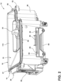
- the sidewall 56 of the housing 14 defines a track tab 68 ( FIG. 2 ) that retains the plate 66 in close proximity to an exterior of the housing 14.
- the housing 14 defines a slot 70 elongated along the second axis B.
- the tub 16 defines a channel 72 that includes a first portion 74 that extends from a bottom tub surface 76 along the first axis A and a second portion 78 that is opposite the bottom tub surface 76 that extends along the second axis B.
- the second locking member 28 e.g., the protrusion
- the second portion 78 may be angled towards the bottom tub surface 76 to facilitate insertion and removal of the second locking member 28.
- the second moveable bracket 60 may be generally U-shaped and include a pair of prongs 80.
- the plate 66 may include a pair of plates 66 with each plate 66 connected to separate prongs 80.
- the second locking member 28 may include a plurality of protrusions with one or more protrusions on each plate 66.
- each plate 66 includes at least two protrusions and each protrusion may be located in a distinct slot 70 and channel 72.
- the linkage 62 extends between and is pivotally connected to the first moveable bracket 58 and is pivotally connected to the second moveable bracket 60.
- a first spring element 82 e.g., at least one helical spring biases the first moveable bracket 58 away from the actuated position and a second spring element 84 (e.g., at least one helical spring) biases the second moveable bracket 60 away from the actuated position.
- the first moveable bracket 58 and the housing 14 each define cooperating first element pockets 86 and ends of the first spring element 82 are located in the cooperating first element pockets 86 to bias the first moveable bracket 58 upwardly along the first axis A.
- the second moveable bracket 60 and the housing 14 each define cooperating second element posts 88 ( FIG. 5 ), and ends of the second spring element 84 are located over the cooperating second element posts 88 to bias the second moveable bracket 60 along the second axis B towards the first moveable bracket 58.
- the tub 16 defines a post 90
- the housing 14 defines an aperture 92 ( FIG. 5 ).
- the post 90 is located in the aperture 92 and biased away from the aperture 92 by a third spring element 94 (e.g., at least one helical spring) to push the tub 16 away from the housing 14 when the knob 23 is in the unlocked position and the push button assembly 26 is in the actuated position.
- a pawl 96 may be pivotally connected to the housing 14 and the third spring element 94 may bias the pawl 96 into contact with the post 90.
- the knob 23 includes a stem 98 ( FIG. 7 ) extending through the opening 20 to an annular valve 100 that is rotatably fixed with the knob 23.
- the annular valve 100 includes an annular rim 102 and a door 104 located within the annular rim 102.
- the door 104 is rotatable with respect to the opening 20 between a closed position where the opening 20 is obstructed by the door 104, and an open position ( FIG. 10 ) where the opening 20 is unobstructed by the door 104.
- the annular rim 102 may be coupled with the first locking member 24, and the first locking member 24 may be configured as at least one flange.
- the housing 14 includes at least one cantilever 108 that is radially and circumferentially aligned with the first locking member 24 to axially retain the annular valve 100 in the locked position.
- the at least one cantilever 108 is circumferentially spaced from the first locking member 24 in the unlocked position.
- the open position of the door 104 corresponds to the locked position of the first locking member 24 and the closed position of the door 104 corresponds to the unlocked position of the first locking member 24.
- the first locking member 24 includes a plurality of flanges (e.g., three) circumferentially spaced around the annular rim 102, and the at least one cantilever 108 includes a plurality of cantilevers 108 (e.g., three) circumferentially spaced equally to the plurality of flanges.
- the knob 23 may be connected to a sift element 110 that is at least partially located in the pocket 18 of the tub 16. More particularly, the sift element 110 may include a grate-type shape that is spaced from the opening 20.
- the pocket 18 may be defined by an internal tub surface 112 that is generally funnel-shaped for routing beans into the opening 20.
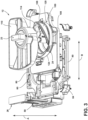
- the sift element 110 includes a guide 114 ( FIG. 3 ) that defines a contour that closely matches the shape of the internal tub surface 112.
- the sift element 110 further includes a rod 116 that extends through the tub 16 to a stationary door element 118.
- the knob 23 rotates relative to the sift element 110 such that rotation of the knob 23 does not move the stationary door element 118.
- a bow cam element 120 is fixedly coupled to the tub 16 with a connection bracket 122.
- the connection bracket 122 includes a central bend 124 (e.g., about 90°) and the tub 16 includes a bracket retaining slit 126 that connects to the connection bracket 122 ( FIG. 8 ).
- the annular valve 100 includes a top surface 128 and a bottom surface 130.
- the top surface 128 of the annular rim 102 includes an inner annular cam surface 132 and an outer annular cam surface 134.
- the inner annular cam surface 132 is located radially inwardly from the outer annular cam surface 134 and extends upwardly towards the knob 23 at a smaller distance than the outer annular cam surface 134. In this manner, the inner annular cam surface 132 and the outer annular cam surface 134 may contact the bottom tub surface 76 (e.g., a funnel-shaped portion of the bottom tub surface 76).
- the bottom tub surface 76 may be funnel-shaped and asymmetric such that the bow cam element 120 may contact and/or otherwise support one or both of the inner annular cam surface 132 and the outer annular cam surface 134.
- the bottom surface 130 of the annular rim 102 may include an inwardly stepped surface 138, and the floor 54 of the housing 14 may define a bean channel 142 that routes beans through the housing 14 to the grinder 22.
- the stationary door element 118 may include a first anchor projection 144 that is fastened to a second anchor projection 146 of the sift element 110 with the rod 116.
- the tub 16 includes an anchor base 148 that extends upwardly from the internal tub surface 112.
- the anchor base 148 includes a stem hole 150 for accommodating the stem 98 of the knob 23 and an anchor hole 152 for accommodating connection of the first anchor projection 144 and the second anchor projection 146.
- the knob 23 rotates relative to the stem hole 150 such that rotation of the knob 23 does not move the stationary door element 118 and the sift element 110 that are connected through the anchor hole 152.
- the first locking member 24 is in the locked position and the door 104 is in an open position (left image in sequence).
- the knob 23 is rotated, the first locking member 24 and the door 104 are contemporaneously rotated to an intermediary position (center image in sequence) and then to the unlocked and closed positions (right image in sequence).
- the push button assembly 26 can be moved to the actuated position to release the second locking member 28.
- the second locking member 28 initially resides within the second portion 78 of the channel 72 (top image in sequence) and, as the push button assembly 26 is moved to the actuated position, the second locking member 28 moves into alignment with the first portion 74 of the channel 72 (center image in sequence).
- the tub 16 can be removed from the housing 14 (bottom image in sequence).
- a bean hopper assembly comprises a housing and a tub at least partially located in the housing.
- the tub defines a pocket configured to hold beans and an opening extends through the tub to route beans into a provided grinder.
- a knob extends through the opening and includes a first locking member that is in a locked position where the tub is fixed to the housing, and an unlocked position where the tub is selectively fixed to the housing.
- a push button assembly includes a second locking member that is selectively moveable to an actuated position when the first locking member is in the unlocked position to release the tub, and where the tub is fixed to the housing when the second locking member is in the actuated position and the first locking member is in the locked position.
- a knob is rotationally fixed to a door and the door is rotatable with respect to an opening between a closed position where the opening is obstructed by the door, and an open position where the opening is unobstructed by the door.
- a door is located within an annular rim and the annular rim includes a first locking member.
- a knob is rotatable to move a first locking member to an unlocked position where a door is located in a closed position, and the knob is rotatable to move the first locking member to a locked position where the door is located in the open position.
- a first locking member includes at least one flange extending from an annular rim and a housing includes at least one cantilever that is radially and circumferentially aligned with the at least one flange to axially retain the annular rim in a locked position and is circumferentially spaced from the flange in an unlocked position.
- At least one flange includes a plurality of flanges circumferentially spaced around an annular rim and at least one cantilever includes a plurality of cantilevers circumferentially spaced equally to the plurality of flanges.
- a push button assembly includes a first moveable bracket and a second moveable bracket pivotally connected to the first moveable bracket by a linkage.
- a first moveable bracket extends along a first axis and a second moveable bracket extends along a second axis that is transverse to the first axis.
- a linkage is configured to translate movement of a first moveable bracket along a first axis into movement of a second moveable bracket along a second axis.
- a second moveable bracket extends along an exterior of a housing.
- a housing defines a slot elongated along a second axis and a tub defines that a channel includes a first portion extending from a bottom tub surface along a first axis and a second portion that is opposite the bottom tub surface that extends along the second axis.
- a second moveable bracket defines a second locking member that includes a protrusion retained in a second portion of a channel and is moveable into alignment with a first portion of the channel when a button assembly is in an actuated position.
- a first spring element biases a first moveable bracket away from an actuated position and a second spring element biases a second moveable bracket away from an actuated position.
- a tub defines a post and a housing defines an aperture.
- the post is located in the aperture and biased away from the aperture by a third spring element to push the tub away from the housing when a knob is in an unlocked position and a push button assembly is in the actuated position.
- a bean hopper assembly includes a housing that has a cantilever and a tub that is at least partially located in the housing over the cantilever.
- the tub defines a pocket configured to hold beans and an opening extends through the tub to route beans into a provided grinder.
- a knob extends through the opening and is rotationally fixed to a first locking member that includes an annular rim that defines a flange.
- the flange extends circumferentially outwardly from the annular rim and is radially and circumferentially aligned with the cantilever in a locked position, and the flange is circumferentially spaced from the cantilever in an unlocked position.
- a push button assembly includes a second locking member that is selectively moveable to an actuated position when the flange is in the unlocked position to release the tub.
- the tub is fixed to the housing when the push button assembly is in the actuated position and the flange is in the locked position.
- a push button assembly includes a first moveable bracket that extends along a first axis and a second moveable bracket that extends along a second axis that is pivotally connected to the first moveable bracket by a linkage.
- the linkage is configured to translate movement of the first moveable bracket along the first axis into movement of the second moveable bracket along the second axis.
- a housing defines a slot elongated along a second axis and a tub defines a channel that includes a first portion that extends from a bottom tub surface along a first axis and a second portion that is opposite the bottom tub surface that extends along the second axis.
- a second moveable bracket defines a second locking member that includes a protrusion retained in a second portion of a channel and is moveable into alignment with a first portion of the channel when a button assembly is in an actuated position.
- a bean hopper comprises a housing and a tub at least partially located in the housing.
- the tub defines a pocket configured to hold beans and an opening extends through the tub to route beans into a provided grinder.
- a knob extends through the opening and includes a first locking member that includes a locked position where the tub is fixed to the housing, and an unlocked position where the tub is selectively fixed to the housing.
- a push button assembly includes a first moveable bracket that extends along a first axis and a second moveable bracket that extends along a second axis that is pivotally connected to the first moveable bracket by a linkage.
- the linkage is configured to translate movement of the first moveable bracket along the first axis into movement of the second moveable bracket along the second axis.
- a second locking member is coupled to the second moveable bracket and defines at least one protrusion that is selectively moveable to an actuated position when the first locking member is in the unlocked position to release the tub.
- the tub is fixed to the housing when the at least one protrusion is in the actuated position and the first locking member is in the locked position.
- a housing defines a slot elongated along a second axis and a tub defines a channel that includes a first portion that extends from a bottom tub surface along a first axis and a second portion that is opposite the bottom tub surface that extends along the second axis. At least one protrusion is retained in the second portion of the channel and is moveable into alignment with the first portion of the channel when a button assembly is in an actuated position.
- the term "coupled” in all of its forms, couple, coupling, coupled, etc. generally means the joining of two components (electrical or mechanical) directly or indirectly to one another. Such joining may be stationary in nature or movable in nature. Such joining may be achieved with the two components (electrical or mechanical) and any additional intermediate members being integrally formed as a single unitary body with one another or with the two components. Such joining may be permanent in nature or may be removable or releasable in nature unless otherwise stated.
- elements shown as integrally formed may be constructed of multiple parts or elements shown as multiple parts may be integrally formed, the operation of the interfaces may be reversed or otherwise varied, the length or width of the structures and/or members or connectors or other elements of the system may be varied, and the nature or number of adjustment positions provided between the elements may be varied.
- the elements and/or assemblies of the system may be constructed from any of a wide variety of materials that provide sufficient strength or durability, in any of a wide variety of colors, textures, and combinations. Accordingly, all such modifications are intended to be included within the scope of the present innovations. Other substitutions, modifications, changes, and omissions may be made in the design, operating conditions, and arrangement of the desired and other exemplary embodiments without departing from the spirit of the present innovations.
Landscapes
- Engineering & Computer Science (AREA)
- Food Science & Technology (AREA)
- Mechanical Engineering (AREA)
- Apparatus For Making Beverages (AREA)
- Filling Or Emptying Of Bunkers, Hoppers, And Tanks (AREA)
- Beans For Foods Or Fodder (AREA)
Abstract
Description
- The present disclosure generally relates to bean hopper assembly, and, more specifically, to a bean hopper assembly that is removable from a brewing assembly.
- According to one aspect of the present disclosure, a bean hopper assembly includes a housing and a tub at least partially located in the housing. The tub defines a pocket configured to hold beans, and an opening extends through the tub to route beans into a provided grinder. A knob extends through the opening and includes a first locking member that includes a locked position where the tub is fixed to the housing, and an unlocked position where the tub is selectively fixed to the housing. A push button assembly includes a second locking member that is selectively moveable to an actuated position when the first locking member is in the unlocked position to release the tub, and where the tub is fixed to the housing when the second locking member is in the actuated position and the first locking member is in the locked position.
- According to another aspect of the present disclosure, a bean hopper assembly includes a housing that includes a cantilever and a tub that is at least partially located in the housing over the cantilever. The tub defines a pocket configured to hold beans and an opening extends through the tub to route beans into a provided grinder. A knob extends through the opening and is rotationally fixed to a first locking member that includes an annular rim that defines a flange. The flange extends circumferentially outwardly from the annular rim and is radially and circumferentially aligned with the cantilever in a locked position, and the flange is circumferentially spaced from the cantilever in an unlocked position. A push button assembly includes a second locking member that is selectively moveable to an actuated position when the flange is in the unlocked position to release the tub. The tub is fixed to the housing when the push button assembly is in the actuated position and the flange is in the locked position.
- According to yet another aspect of the present disclosure, a bean hopper assembly includes a housing and a tub at least partially located in the housing. The tub defines a pocket configured to hold beans, and an opening extends through the tub to route beans into a provided grinder. A knob extends through the opening and includes a first locking member that includes a locked position where the tub is fixed to the housing, and an unlocked position where the tub is selectively fixed to the housing. A push button assembly includes a first moveable bracket that extends along a first axis and a second moveable bracket that extends along a second axis that is pivotally connected to the first moveable bracket by a linkage. The linkage is configured to translate movement of the first moveable bracket along the first axis into movement of the second moveable bracket along the second axis. A second locking member is coupled to the second moveable bracket and defines at least one protrusion that is selectively moveable to an actuated position when the first locking member is in the unlocked position to release the tub. The tub is fixed to the housing when the at least one protrusion is in the actuated position and the first locking member is in the locked position.
- These and other features, advantages, and objects of the present disclosure will be further understood and appreciated by those skilled in the art by reference to the following specification, claims, and appended drawings.
- In the drawings:
-
FIG. 1 is a front perspective view of a brewing assembly according to an aspect of the present disclosure; -
FIG. 2 is a top perspective view of a bean hopper assembly removed from the brewing assembly according to an aspect of the present disclosure; -
FIG. 3 is a top perspective view of components of the bean hopper assembly removed from a tub and a housing according to an aspect of the present disclosure; -
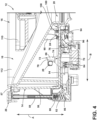
Fig. 4 is a cross-sectional side view from a first side of the bean hopper assembly according to an aspect of the present disclosure; -
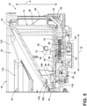
Fig. 5 is a cross-sectional side view from a second side of the bean hopper assembly according to an aspect of the present disclosure; -
FIG. 6 is a bottom view of the bean hopper assembly according to an aspect of the present disclosure; -
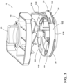
FIG. 7 is a top perspective view of a knob and a first locking member isolated from other components of the bean hopper assembly according to an aspect of the present disclosure; -
FIG. 8 is a cross-sectional side view of the knob and the first locking member integrated with the other components of the bean hopper assembly according to an aspect of the present disclosure; -
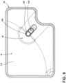
FIG. 9 is a top view of the tub isolated from other components of the bean hopper assembly according to an aspect of the present disclosure; -
FIG. 10 is a sequence of bottom view of the bean hopper assembly illustrating an annular valve moved between an open position and a closed position according to an aspect of the present disclosure; and -
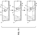
FIG. 11 is an interior side view of the bean hopper assembly illustrating a second locking member moved between a rested position and an actuated position according to an aspect of the present disclosure. - The components in the figures are not necessarily to scale, emphasis instead being placed upon illustrating the principles described herein.
- The present illustrated embodiments reside primarily in combinations of method steps and apparatus components related to a bean hopper assembly that is removable from a grinder. Accordingly, the apparatus components and method steps have been represented, where appropriate, by conventional symbols in the drawings, showing only those specific details that are pertinent to understanding the embodiments of the present disclosure so as not to obscure the disclosure with details that will be readily apparent to those of ordinary skill in the art having the benefit of the description herein. Further, like numerals in the description and drawings represent like elements.
- For purposes of description herein, the terms "upper," "lower," "right," "left," "rear," "front," "vertical," "horizontal," and derivatives thereof shall relate to the disclosure as oriented in
FIG. 1 . Unless stated otherwise, the term "front" shall refer to the surface of the element closer to an intended viewer, and the term "rear" shall refer to the surface of the element further from the intended viewer. However, it is to be understood that the disclosure may assume various alternative orientations, except where expressly specified to the contrary. It is also to be understood that the specific devices and processes illustrated in the attached drawings, and described in the following specification are simply exemplary embodiments of the inventive concepts defined in the appended claims. Hence, specific dimensions and other physical characteristics relating to the embodiments disclosed herein are not to be considered as limiting, unless the claims expressly state otherwise. - The terms "including," "comprises," "comprising," or any other variation thereof, are intended to cover a non-exclusive inclusion, such that a process, method, article, or apparatus that comprises a list of elements does not include only those elements but may include other elements not expressly listed or inherent to such process, method, article, or apparatus. An element preceded by "comprises a... " does not, without more constraints, preclude the existence of additional identical elements in the process, method, article, or apparatus that comprises the element.
- Referring to
FIGS. 1-11 ,reference numeral 10 generally designates a brewing assembly (e.g., a coffee maker, an espresso maker, and/or the like). Thebrewing assembly 10 includes abean hopper assembly 12 that includes ahousing 14 and atub 16 at least partially located in thehousing 14. Thetub 16 defines apocket 18 that is configured to hold beans used to brew beverages with thebrewing assembly 10. Anopening 20 extends through thetub 16 for routing beans into a grinder 22 (FIGS. 1 ,4 , and9 ). Aknob 23 extends through the opening 20 and includes a first locking member 24 (FIG. 7 ). Thefirst locking member 24 includes a locked position where thetub 16 is fixed to thehousing 14, and an unlocked position where thetub 16 is selectively fixed to thehousing 14. Apush button assembly 26 includes asecond locking member 28 that is selectively moveable to an actuated position when thefirst locking member 24 is in the unlocked position to release thetub 16, and where thetub 16 is fixed to thehousing 14 when thesecond locking member 28 is in the actuated position and thefirst locking member 24 is in the locked position (FIGS. 3 and4 ). - With reference now to
FIGS. 1 and2 , thebrewing assembly 10 may include asupport base 30 and apedestal portion 32 extending from thesupport base 30. Thegrinder 22 may be located within agrinder housing 34 extending from thepedestal portion 32 that is opposite thesupport base 30. Thebrewing assembly 10 may include abeverage container 36 located under thegrinder housing 34. Thebrewing assembly 10 may further include auser interface 38 that may include adisplay screen 40, a pressure gauge 42, and a plurality of buttons and/ordials 44 for operating thebrewing assembly 10. Aliquid reservoir 46 and a usedbean bin 48 may be located in thesupport base 30, thepedestal portion 32, or the grinder housing 34. In use, thegrinder 22 selectively receives beans from thebean hopper assembly 12 for grinding where ground beans can be further processed for brewing via a heated liquid (which may be pressurized) from theliquid reservoir 46. The brewed liquid is then routed to thebeverage container 36 and the used and ground coffee beans are routed to the used bean bin 48. Acover 49 may be located over thetub 16 to retain the beans within thepocket 18. - With reference now to
FIGS. 2-4 , thehousing 14 may be connected to thegrinder housing 34 with a series ofconnection tabs 50 andfastener apertures 52. In this manner, thehousing 14 may be configured to be permanently connected to the grinder housing 34 (i.e., not removable without tools). Thehousing 14 includes afloor 54 and asidewall 56 that extends from thefloor 54 to arim 57 to define a space for locating thetub 16. Thepush button assembly 26 includes a firstmoveable bracket 58 that extends along a first axis "A" and a secondmoveable bracket 60 that extends along a second axis "B." The secondmoveable bracket 60 is pivotally connected to the firstmoveable bracket 58 by a linkage 62 (FIG. 4 ) that is configured to translate movement of the firstmoveable bracket 58 along the first axis A into movement of the secondmoveable bracket 60 along the second axis B. Thesecond locking member 28 is coupled to the secondmoveable bracket 60 and is configured as at least one protrusion that is selectively moveable to the actuated position when the first lockingmember 24 is in the unlocked position to release thetub 16. However, thetub 16 remains fixed to thehousing 14 when thesecond locking member 28 is in the actuated position and the first lockingmember 24 is in the locked position. More particularly, thesecond locking member 28 may be located on aplate 66 connected to the secondmoveable bracket 60. Thesidewall 56 of thehousing 14 defines a track tab 68 (FIG. 2 ) that retains theplate 66 in close proximity to an exterior of thehousing 14. - With reference now to
FIG. 4 , thehousing 14 defines aslot 70 elongated along the second axis B. Thetub 16 defines achannel 72 that includes afirst portion 74 that extends from abottom tub surface 76 along the first axis A and asecond portion 78 that is opposite thebottom tub surface 76 that extends along the second axis B. The second locking member 28 (e.g., the protrusion) is retained in thesecond portion 78 of thechannel 72 and is moveable into alignment with thefirst portion 74 of thechannel 72 when thepush button assembly 26 is in the actuated position. Thesecond portion 78 may be angled towards thebottom tub surface 76 to facilitate insertion and removal of thesecond locking member 28. With reference now toFIG. 5 , the secondmoveable bracket 60 may be generally U-shaped and include a pair ofprongs 80. Theplate 66 may include a pair ofplates 66 with eachplate 66 connected to separateprongs 80. Thesecond locking member 28 may include a plurality of protrusions with one or more protrusions on eachplate 66. In some embodiments, eachplate 66 includes at least two protrusions and each protrusion may be located in adistinct slot 70 andchannel 72. - With reference to
FIGS. 4 and5 , thelinkage 62 extends between and is pivotally connected to the firstmoveable bracket 58 and is pivotally connected to the secondmoveable bracket 60. A first spring element 82 (e.g., at least one helical spring) biases the firstmoveable bracket 58 away from the actuated position and a second spring element 84 (e.g., at least one helical spring) biases the secondmoveable bracket 60 away from the actuated position. More particularly, the firstmoveable bracket 58 and thehousing 14 each define cooperating first element pockets 86 and ends of thefirst spring element 82 are located in the cooperating first element pockets 86 to bias the firstmoveable bracket 58 upwardly along the first axis A. The secondmoveable bracket 60 and thehousing 14 each define cooperating second element posts 88 (FIG. 5 ), and ends of thesecond spring element 84 are located over the cooperating second element posts 88 to bias the secondmoveable bracket 60 along the second axis B towards the firstmoveable bracket 58. Thetub 16 defines apost 90, and thehousing 14 defines an aperture 92 (FIG. 5 ). Thepost 90 is located in theaperture 92 and biased away from theaperture 92 by a third spring element 94 (e.g., at least one helical spring) to push thetub 16 away from thehousing 14 when theknob 23 is in the unlocked position and thepush button assembly 26 is in the actuated position. More particularly, apawl 96 may be pivotally connected to thehousing 14 and thethird spring element 94 may bias thepawl 96 into contact with thepost 90. - With reference now to
FIGS. 2 ,3 ,7 , and8 , theknob 23 includes a stem 98 (FIG. 7 ) extending through theopening 20 to anannular valve 100 that is rotatably fixed with theknob 23. Theannular valve 100 includes anannular rim 102 and adoor 104 located within theannular rim 102. Thedoor 104 is rotatable with respect to theopening 20 between a closed position where theopening 20 is obstructed by thedoor 104, and an open position (FIG. 10 ) where theopening 20 is unobstructed by thedoor 104. Theannular rim 102 may be coupled with the first lockingmember 24, and the first lockingmember 24 may be configured as at least one flange. Thehousing 14 includes at least onecantilever 108 that is radially and circumferentially aligned with the first lockingmember 24 to axially retain theannular valve 100 in the locked position. The at least onecantilever 108 is circumferentially spaced from the first lockingmember 24 in the unlocked position. In some embodiments, the open position of thedoor 104 corresponds to the locked position of the first lockingmember 24 and the closed position of thedoor 104 corresponds to the unlocked position of the first lockingmember 24. In some embodiments, the first lockingmember 24 includes a plurality of flanges (e.g., three) circumferentially spaced around theannular rim 102, and the at least onecantilever 108 includes a plurality of cantilevers 108 (e.g., three) circumferentially spaced equally to the plurality of flanges. - With reference now to
FIGS. 2 ,3 , and7-9 , theknob 23 may be connected to a siftelement 110 that is at least partially located in thepocket 18 of thetub 16. More particularly, the siftelement 110 may include a grate-type shape that is spaced from theopening 20. Thepocket 18 may be defined by aninternal tub surface 112 that is generally funnel-shaped for routing beans into theopening 20. The siftelement 110 includes a guide 114 (FIG. 3 ) that defines a contour that closely matches the shape of theinternal tub surface 112. The siftelement 110 further includes arod 116 that extends through thetub 16 to astationary door element 118. Theknob 23 rotates relative to the siftelement 110 such that rotation of theknob 23 does not move thestationary door element 118. Abow cam element 120 is fixedly coupled to thetub 16 with aconnection bracket 122. Theconnection bracket 122 includes a central bend 124 (e.g., about 90°) and thetub 16 includes a bracket retaining slit 126 that connects to the connection bracket 122 (FIG. 8 ). - With reference now to
FIG. 8 , theannular valve 100 includes atop surface 128 and abottom surface 130. Thetop surface 128 of theannular rim 102 includes an innerannular cam surface 132 and an outerannular cam surface 134. The innerannular cam surface 132 is located radially inwardly from the outerannular cam surface 134 and extends upwardly towards theknob 23 at a smaller distance than the outerannular cam surface 134. In this manner, the innerannular cam surface 132 and the outerannular cam surface 134 may contact the bottom tub surface 76 (e.g., a funnel-shaped portion of the bottom tub surface 76). Thebottom tub surface 76 may be funnel-shaped and asymmetric such that thebow cam element 120 may contact and/or otherwise support one or both of the innerannular cam surface 132 and the outerannular cam surface 134. Thebottom surface 130 of theannular rim 102 may include an inwardly steppedsurface 138, and thefloor 54 of thehousing 14 may define abean channel 142 that routes beans through thehousing 14 to thegrinder 22. Thestationary door element 118 may include afirst anchor projection 144 that is fastened to asecond anchor projection 146 of the siftelement 110 with therod 116. - With reference to
FIG. 9 , thetub 16 includes ananchor base 148 that extends upwardly from theinternal tub surface 112. Theanchor base 148 includes astem hole 150 for accommodating thestem 98 of theknob 23 and ananchor hole 152 for accommodating connection of thefirst anchor projection 144 and thesecond anchor projection 146. In this manner, theknob 23 rotates relative to thestem hole 150 such that rotation of theknob 23 does not move thestationary door element 118 and the siftelement 110 that are connected through theanchor hole 152. - With reference to
FIG. 10 , the first lockingmember 24 is in the locked position and thedoor 104 is in an open position (left image in sequence). As theknob 23 is rotated, the first lockingmember 24 and thedoor 104 are contemporaneously rotated to an intermediary position (center image in sequence) and then to the unlocked and closed positions (right image in sequence). With reference now toFIG. 11 , when the first lockingmember 24 is in the unlocked position and the door is in the closed position, thepush button assembly 26 can be moved to the actuated position to release thesecond locking member 28. More particularly, thesecond locking member 28 initially resides within thesecond portion 78 of the channel 72 (top image in sequence) and, as thepush button assembly 26 is moved to the actuated position, thesecond locking member 28 moves into alignment with thefirst portion 74 of the channel 72 (center image in sequence). When thesecond locking member 28 is located in alignment with thefirst portion 74 and the first lockingmember 24 is in the unlocked position, thetub 16 can be removed from the housing 14 (bottom image in sequence). - The invention disclosed herein is further summarized in the following paragraphs and is further characterized by combinations of any and all of the various aspects described therein.
- According to another aspect of the present disclosure, a bean hopper assembly is provided. The bean hopper assembly comprises a housing and a tub at least partially located in the housing. The tub defines a pocket configured to hold beans and an opening extends through the tub to route beans into a provided grinder. A knob extends through the opening and includes a first locking member that is in a locked position where the tub is fixed to the housing, and an unlocked position where the tub is selectively fixed to the housing. A push button assembly includes a second locking member that is selectively moveable to an actuated position when the first locking member is in the unlocked position to release the tub, and where the tub is fixed to the housing when the second locking member is in the actuated position and the first locking member is in the locked position.
- According to another aspect, a knob is rotationally fixed to a door and the door is rotatable with respect to an opening between a closed position where the opening is obstructed by the door, and an open position where the opening is unobstructed by the door.
- According to another aspect, a door is located within an annular rim and the annular rim includes a first locking member.
- According to another aspect, a knob is rotatable to move a first locking member to an unlocked position where a door is located in a closed position, and the knob is rotatable to move the first locking member to a locked position where the door is located in the open position.
- According to another aspect, a first locking member includes at least one flange extending from an annular rim and a housing includes at least one cantilever that is radially and circumferentially aligned with the at least one flange to axially retain the annular rim in a locked position and is circumferentially spaced from the flange in an unlocked position.
- According to another aspect, at least one flange includes a plurality of flanges circumferentially spaced around an annular rim and at least one cantilever includes a plurality of cantilevers circumferentially spaced equally to the plurality of flanges.
- According to another aspect, a push button assembly includes a first moveable bracket and a second moveable bracket pivotally connected to the first moveable bracket by a linkage.
- According to another aspect, a first moveable bracket extends along a first axis and a second moveable bracket extends along a second axis that is transverse to the first axis.
- According to another aspect, a linkage is configured to translate movement of a first moveable bracket along a first axis into movement of a second moveable bracket along a second axis.
- According to another aspect, a second moveable bracket extends along an exterior of a housing.
- According to another aspect, a housing defines a slot elongated along a second axis and a tub defines that a channel includes a first portion extending from a bottom tub surface along a first axis and a second portion that is opposite the bottom tub surface that extends along the second axis.
- According to another aspect, a second moveable bracket defines a second locking member that includes a protrusion retained in a second portion of a channel and is moveable into alignment with a first portion of the channel when a button assembly is in an actuated position.
- According to another aspect, a first spring element biases a first moveable bracket away from an actuated position and a second spring element biases a second moveable bracket away from an actuated position.
- According to another aspect, a tub defines a post and a housing defines an aperture. The post is located in the aperture and biased away from the aperture by a third spring element to push the tub away from the housing when a knob is in an unlocked position and a push button assembly is in the actuated position.
- According to yet another aspect of the present disclosure, a bean hopper assembly includes a housing that has a cantilever and a tub that is at least partially located in the housing over the cantilever. The tub defines a pocket configured to hold beans and an opening extends through the tub to route beans into a provided grinder. A knob extends through the opening and is rotationally fixed to a first locking member that includes an annular rim that defines a flange. The flange extends circumferentially outwardly from the annular rim and is radially and circumferentially aligned with the cantilever in a locked position, and the flange is circumferentially spaced from the cantilever in an unlocked position. A push button assembly includes a second locking member that is selectively moveable to an actuated position when the flange is in the unlocked position to release the tub. The tub is fixed to the housing when the push button assembly is in the actuated position and the flange is in the locked position.
- According to another aspect, a push button assembly includes a first moveable bracket that extends along a first axis and a second moveable bracket that extends along a second axis that is pivotally connected to the first moveable bracket by a linkage. The linkage is configured to translate movement of the first moveable bracket along the first axis into movement of the second moveable bracket along the second axis.
- According to another aspect, a housing defines a slot elongated along a second axis and a tub defines a channel that includes a first portion that extends from a bottom tub surface along a first axis and a second portion that is opposite the bottom tub surface that extends along the second axis.
- According to another aspect, a second moveable bracket defines a second locking member that includes a protrusion retained in a second portion of a channel and is moveable into alignment with a first portion of the channel when a button assembly is in an actuated position.
- According to yet another aspect of the present disclosure, a bean hopper comprises a housing and a tub at least partially located in the housing. The tub defines a pocket configured to hold beans and an opening extends through the tub to route beans into a provided grinder. A knob extends through the opening and includes a first locking member that includes a locked position where the tub is fixed to the housing, and an unlocked position where the tub is selectively fixed to the housing. A push button assembly includes a first moveable bracket that extends along a first axis and a second moveable bracket that extends along a second axis that is pivotally connected to the first moveable bracket by a linkage. The linkage is configured to translate movement of the first moveable bracket along the first axis into movement of the second moveable bracket along the second axis. A second locking member is coupled to the second moveable bracket and defines at least one protrusion that is selectively moveable to an actuated position when the first locking member is in the unlocked position to release the tub. The tub is fixed to the housing when the at least one protrusion is in the actuated position and the first locking member is in the locked position.
- According to another aspect, a housing defines a slot elongated along a second axis and a tub defines a channel that includes a first portion that extends from a bottom tub surface along a first axis and a second portion that is opposite the bottom tub surface that extends along the second axis. At least one protrusion is retained in the second portion of the channel and is moveable into alignment with the first portion of the channel when a button assembly is in an actuated position.
- It will be understood by one having ordinary skill in the art that construction of the described disclosure and other components is not limited to any specific material. Other exemplary embodiments of the disclosure disclosed herein may be formed from a wide variety of materials, unless described otherwise herein.
- For purposes of this disclosure, the term "coupled" (in all of its forms, couple, coupling, coupled, etc.) generally means the joining of two components (electrical or mechanical) directly or indirectly to one another. Such joining may be stationary in nature or movable in nature. Such joining may be achieved with the two components (electrical or mechanical) and any additional intermediate members being integrally formed as a single unitary body with one another or with the two components. Such joining may be permanent in nature or may be removable or releasable in nature unless otherwise stated.
- It is also important to note that the construction and arrangement of the elements of the disclosure as shown in the exemplary embodiments is illustrative only. Although only a few embodiments of the present innovations have been described in detail in this disclosure, those skilled in the art who review this disclosure will readily appreciate that many modifications are possible (e.g., variations in sizes, dimensions, structures, shapes and proportions of the various elements, values of parameters, mounting arrangements, use of materials, colors, orientations, etc.) without materially departing from the novel teachings and advantages of the subject matter recited. For example, elements shown as integrally formed may be constructed of multiple parts or elements shown as multiple parts may be integrally formed, the operation of the interfaces may be reversed or otherwise varied, the length or width of the structures and/or members or connectors or other elements of the system may be varied, and the nature or number of adjustment positions provided between the elements may be varied. It should be noted that the elements and/or assemblies of the system may be constructed from any of a wide variety of materials that provide sufficient strength or durability, in any of a wide variety of colors, textures, and combinations. Accordingly, all such modifications are intended to be included within the scope of the present innovations. Other substitutions, modifications, changes, and omissions may be made in the design, operating conditions, and arrangement of the desired and other exemplary embodiments without departing from the spirit of the present innovations.
- It will be understood that any described processes or steps within described processes may be combined with other disclosed processes or steps to form structures within the scope of the present disclosure. The exemplary structures and processes disclosed herein are for illustrative purposes and are not to be construed as limiting.
Claims (15)
- A bean hopper assembly (12) comprising:a housing (14);a tub (16) at least partially located in the housing (14) defining a pocket (18) configured to hold beans, an opening (20) extending through the tub (16) and configured for routing beans, in particular for routing beans into a grinder (22);a knob (23) extending through the opening (20) and including a first locking member (24) configured to be toggled between a locked position where the tub (16) is fixed to the housing (14) and an unlocked position where the tub (16) is selectively fixed to the housing (16); anda push button assembly (26) including a second locking member (28) configured to be selectively moved to an actuated position when the first locking member (24) is in the unlocked position to release the tub (16).
- The bean hopper assembly (12) of claim 1, wherein the tub (16) is fixed to the housing (14) when the second locking member (28) is in the actuated position and the first locking member (24) is in the locked position.
- The bean hopper assembly (12) of claim 1 or claim 2, wherein the knob (23) is rotationally fixed to a door (104) and the door (104) is rotatable with respect to the opening (20) between a closed position where the opening (20) is obstructed by the door (104) and an open position where the opening (20) is unobstructed by the door (104).
- The bean hopper assembly (12) of claim 3, wherein the door (104) is located within an annular rim (102) and the annular rim (102) includes the first locking member (24), optionally wherein the knob (23) is rotatable to move the first locking member (24) to the unlocked position where the door (104) is located in the closed position and the knob (23) is rotatable to move the first locking member (24) to the locked position where the door (104) is located in the open position.
- The bean hopper assembly (12) of claim 4, wherein the first locking member (24) includes at least one flange extending from the annular rim (102) and the housing (14) includes at least one cantilever (108), the at least one cantilever (108) being radially and circumferentially aligned with the at least one flange to axially retain the annular rim (102) in the locked position and being circumferentially spaced from the flange in the unlocked position, optionally wherein the at least one flange includes a plurality of flanges circumferentially spaced around the annular rim (102) and the at least one cantilever (108) includes a plurality of cantilevers circumferentially spaced equally to the plurality of flanges.
- The bean hopper assembly (12) of any one of the previous claims, wherein the push button assembly (26) includes a first moveable bracket (58) and a second moveable bracket (60) pivotally connected to the first moveable bracket (58) by a linkage (62), optionally wherein the second moveable bracket (60) extends along an exterior of the housing (14).
- The bean hopper assembly (12) of claim 6, wherein the first moveable bracket (58) extends along a first axis (A) and the second moveable bracket (60) extends along a second axis (B) transverse to the first axis (A), optionally wherein the linkage (62) is configured to translate movement of the first moveable bracket (58) along the first axis (A) into movement of the second moveable bracket (60) along the second axis (B).
- The bean hopper assembly (12) of claim 7, wherein the housing (14) defines a slot (70) elongated along the second axis (B) and the tub (16) defines a channel (72) including a first portion (74) extending from a bottom surface (76) of the tub (16) and a second portion (78) opposite the bottom surface (76) of the tub (16), the first portion (74) of the channel (72) extending along the first axis (A) and the second portion (78) of the channel (72) extending along the second axis (B), optionally wherein the second moveable bracket (60) defines the second locking member (28), the second locking member (28) including a protrusion retained in the second portion (78) of the channel (72) and being moveable into alignment with the first portion (74) of the channel (72) when the push button assembly (26) is in the actuated position.
- The bean hopper assembly (12) of any one of claims 6 to 8, further comprising a first spring element (82) and a second spring element (84), wherein the first spring element (82) is configured to bias the first moveable bracket (58) away from the actuated position and the second spring element (84) is configured to bias the second moveable bracket (60) away from the actuated position, optionally wherein the bean hopper assembly (12) further comprises a third spring element (82) and wherein the tub (16) defines a post (90) and the housing (14) defines an aperture (92), the post (90) being located in the aperture (92) and being configured to be biased away from the aperture (92) by the third spring element (82) to push the tub (16) away from the housing (14) when the knob (23) is in the unlocked position and the push button assembly (26) is in the actuated position.
- The bean hopper assembly (12) of any one of the previous claims, wherein the push button assembly (26) is configured to lift, when actuated, the tub (16) from the housing (14) to facilitate removal of the tub (16) from the bean hopper assembly (12).
- The bean hopper assembly (12) of any one of the previous claims, wherein the housing (14) defines a cantilever (108), wherein the tub (16) is at least partially located over the cantilever (108), wherein the first locking member (24) includes an annular rim (102) defining a flange extending circumferentially outwardly from the annular rim (102), wherein the knob (23) is rotationally fixed to the first locking member (24), wherein the flange is radially and circumferentially aligned with the cantilever (108) in a locked position and is circumferentially spaced from the cantilever (108) in an unlocked position and wherein the second locking member (28) is selectively moveable to an actuated position when the flange is in the unlocked position to release the tub (16), optionally wherein the tub (16) is fixed to the housing (14) when the push button assembly (26) is in the actuated position and the flange is in the locked position.
- The bean hopper assembly (12) of any one of the previous claims, wherein the push button assembly (26) includes a first moveable bracket (58) extending along a first axis (A) and a second moveable bracket (60) extending along a second axis (B) pivotally connected to the first moveable bracket (58) by a linkage (62) configured to translate movement of the first moveable bracket (58) along the first axis (A) into movement of the second moveable bracket (60) along the second axis (B) and wherein the second locking member (28) is coupled to the second moveable bracket (60) and defines at least one protrusion selectively moveable to an actuated position when the first locking member (24) is in the unlocked position to release the tub (16), optionally wherein the tub (16) is fixed to the housing (14) when the at least one protrusion is in the actuated position and the first locking member (24) is in the locked position.
- A brewing assembly (10), in particular a coffee maker or an espresso maker, the brewing assembly (10) comprising:a user interface (38) including in particular a digital screen;a grinder (22); anda bean hopper assembly (12) according to any one of the previous claims, wherein the opening (20) is configured for routing beans into the grinder (22).
- The brewing assembly (10) of claim 13, wherein the user interface (38) is configured, when the first locking member (24) is in the unlocked position and/or when the door (104) is in the closed position, to notify a user to rotate the knob (23) to enable a drink menu to be displayed or to actuate the push button (18) to remove the tub (14) from the brewing assembly (10).
- The brewing assembly (10) of claim 13 or 14, further comprising internal fluid and bean lines, the brewing assembly (10) being configured to operate a purging cycle allowing a cleaning of the internal fluid and bean lines, wherein the user interface (38) is configured, when the first locking member (24) is in the unlocked position and/or when the door (104) is in the closed position, to permit a user to run the purging cycle.
Priority Applications (1)
| Application Number | Priority Date | Filing Date | Title |
|---|---|---|---|
| EP25186339.5A EP4620364A3 (en) | 2022-11-22 | 2023-11-22 | Bean hopper assembly |
Applications Claiming Priority (1)
| Application Number | Priority Date | Filing Date | Title |
|---|---|---|---|
| US18/057,839 US20240164581A1 (en) | 2022-11-22 | 2022-11-22 | Removable bean hopper assembly |
Related Child Applications (2)
| Application Number | Title | Priority Date | Filing Date |
|---|---|---|---|
| EP25186339.5A Division EP4620364A3 (en) | 2022-11-22 | 2023-11-22 | Bean hopper assembly |
| EP25186339.5A Division-Into EP4620364A3 (en) | 2022-11-22 | 2023-11-22 | Bean hopper assembly |
Publications (2)
| Publication Number | Publication Date |
|---|---|
| EP4374750A1 true EP4374750A1 (en) | 2024-05-29 |
| EP4374750B1 EP4374750B1 (en) | 2025-11-05 |
Family
ID=88923657
Family Applications (2)
| Application Number | Title | Priority Date | Filing Date |
|---|---|---|---|
| EP23211567.5A Active EP4374750B1 (en) | 2022-11-22 | 2023-11-22 | Removable bean hopper assembly |
| EP25186339.5A Pending EP4620364A3 (en) | 2022-11-22 | 2023-11-22 | Bean hopper assembly |
Family Applications After (1)
| Application Number | Title | Priority Date | Filing Date |
|---|---|---|---|
| EP25186339.5A Pending EP4620364A3 (en) | 2022-11-22 | 2023-11-22 | Bean hopper assembly |
Country Status (4)
| Country | Link |
|---|---|
| US (1) | US20240164581A1 (en) |
| EP (2) | EP4374750B1 (en) |
| CN (1) | CN118058618A (en) |
| AU (1) | AU2023237118A1 (en) |
Citations (4)
| Publication number | Priority date | Publication date | Assignee | Title |
|---|---|---|---|---|
| US20090031900A1 (en) * | 2007-06-12 | 2009-02-05 | Barraclough James R | Coffee maker |
| US8051765B2 (en) * | 2006-06-26 | 2011-11-08 | Seb S.A. | Distributor of powdered product with removable reservoir |
| US20160051082A1 (en) * | 2013-04-02 | 2016-02-25 | Koninklijke Philips N.V. | Beverage-producing machine comprising a removable ingredient container |
| US10130215B2 (en) * | 2014-05-30 | 2018-11-20 | Eugster/Frismag Ag | Coffee bean container |
Family Cites Families (1)
| Publication number | Priority date | Publication date | Assignee | Title |
|---|---|---|---|---|
| CN103584734B (en) * | 2012-08-15 | 2015-09-16 | 威斯达电器(中山)制造有限公司 | With the automatic coffee machine of removable bean milling device |
-
2022
- 2022-11-22 US US18/057,839 patent/US20240164581A1/en active Pending
-
2023
- 2023-09-28 AU AU2023237118A patent/AU2023237118A1/en active Pending
- 2023-11-21 CN CN202311558256.XA patent/CN118058618A/en active Pending
- 2023-11-22 EP EP23211567.5A patent/EP4374750B1/en active Active
- 2023-11-22 EP EP25186339.5A patent/EP4620364A3/en active Pending
Patent Citations (4)
| Publication number | Priority date | Publication date | Assignee | Title |
|---|---|---|---|---|
| US8051765B2 (en) * | 2006-06-26 | 2011-11-08 | Seb S.A. | Distributor of powdered product with removable reservoir |
| US20090031900A1 (en) * | 2007-06-12 | 2009-02-05 | Barraclough James R | Coffee maker |
| US20160051082A1 (en) * | 2013-04-02 | 2016-02-25 | Koninklijke Philips N.V. | Beverage-producing machine comprising a removable ingredient container |
| US10130215B2 (en) * | 2014-05-30 | 2018-11-20 | Eugster/Frismag Ag | Coffee bean container |
Also Published As
| Publication number | Publication date |
|---|---|
| EP4620364A3 (en) | 2025-12-24 |
| US20240164581A1 (en) | 2024-05-23 |
| EP4374750B1 (en) | 2025-11-05 |
| AU2023237118A1 (en) | 2024-06-06 |
| EP4620364A2 (en) | 2025-09-24 |
| CN118058618A (en) | 2024-05-24 |
Similar Documents
| Publication | Publication Date | Title |
|---|---|---|
| US12167815B2 (en) | Coffee grinding apparatus with portafilter holder assembly | |
| JP5442006B2 (en) | Plunger filter beverage manufacturer with liquid inlet that can be closed | |
| US7243867B2 (en) | Coffee grinder with coffee bean container | |
| CN103442625B (en) | Container closure | |
| AU2013403894B2 (en) | Hand drip coffee tumbler | |
| US3415497A (en) | Combined blender and spatula | |
| US20200015619A1 (en) | French Press | |
| EP1563774B1 (en) | Spoon brewing apparatus | |
| CN106102529B (en) | Beverage brewing device | |
| EP1287773A2 (en) | Spoon shaped coffee brewing apparatus | |
| JP6362703B2 (en) | Beverage production machine using capsules | |
| CA2677879A1 (en) | Coffee maker with single serve setting | |
| AU2009267719A1 (en) | Beverage preparation device comprising an insert inserted into a receptacle | |
| US20160051082A1 (en) | Beverage-producing machine comprising a removable ingredient container | |
| EP4374750B1 (en) | Removable bean hopper assembly | |
| CN118613193A (en) | Beverage Machine | |
| JP2008543522A (en) | Porter filter system | |
| EP2317896B1 (en) | A cartridge-holder assembly and a cartridge for the preparation of beverages, in particular coffee | |
| US7013797B2 (en) | Capsule magazine unit with a capsule retaining member | |
| EP1915075B1 (en) | Closing mechanism for brewing device | |
| US7322276B2 (en) | Coffee dispenser group, in particular for espresso coffee, for a drinks machine | |
| US7731058B2 (en) | Semi-automatic dispenser for disposable cups | |
| CN105407770B (en) | Machine for preparing beverages with removable filter-holder and element for selecting the operating mode of the machine | |
| EP4464207A1 (en) | Coffee machine drip tray with integrated storage | |
| US8205647B2 (en) | Machine and device for supplying beverages in containers having different sizes and method therefor |
Legal Events
| Date | Code | Title | Description |
|---|---|---|---|
| PUAI | Public reference made under article 153(3) epc to a published international application that has entered the european phase |
Free format text: ORIGINAL CODE: 0009012 |
|
| STAA | Information on the status of an ep patent application or granted ep patent |
Free format text: STATUS: THE APPLICATION HAS BEEN PUBLISHED |
|
| AK | Designated contracting states |
Kind code of ref document: A1 Designated state(s): AL AT BE BG CH CY CZ DE DK EE ES FI FR GB GR HR HU IE IS IT LI LT LU LV MC ME MK MT NL NO PL PT RO RS SE SI SK SM TR |
|
| P01 | Opt-out of the competence of the unified patent court (upc) registered |
Free format text: CASE NUMBER: APP_49085/2024 Effective date: 20240828 |
|
| STAA | Information on the status of an ep patent application or granted ep patent |
Free format text: STATUS: REQUEST FOR EXAMINATION WAS MADE |
|
| 17P | Request for examination filed |
Effective date: 20241025 |
|
| RBV | Designated contracting states (corrected) |
Designated state(s): AL AT BE BG CH CY CZ DE DK EE ES FI FR GB GR HR HU IE IS IT LI LT LU LV MC ME MK MT NL NO PL PT RO RS SE SI SK SM TR |
|
| GRAP | Despatch of communication of intention to grant a patent |
Free format text: ORIGINAL CODE: EPIDOSNIGR1 |
|
| STAA | Information on the status of an ep patent application or granted ep patent |
Free format text: STATUS: GRANT OF PATENT IS INTENDED |
|
| INTG | Intention to grant announced |
Effective date: 20241210 |
|
| GRAJ | Information related to disapproval of communication of intention to grant by the applicant or resumption of examination proceedings by the epo deleted |
Free format text: ORIGINAL CODE: EPIDOSDIGR1 |
|
| STAA | Information on the status of an ep patent application or granted ep patent |
Free format text: STATUS: REQUEST FOR EXAMINATION WAS MADE |
|
| INTC | Intention to grant announced (deleted) | ||
| GRAP | Despatch of communication of intention to grant a patent |
Free format text: ORIGINAL CODE: EPIDOSNIGR1 |
|
| STAA | Information on the status of an ep patent application or granted ep patent |
Free format text: STATUS: GRANT OF PATENT IS INTENDED |
|
| INTG | Intention to grant announced |
Effective date: 20250304 |
|
| GRAJ | Information related to disapproval of communication of intention to grant by the applicant or resumption of examination proceedings by the epo deleted |
Free format text: ORIGINAL CODE: EPIDOSDIGR1 |
|
| STAA | Information on the status of an ep patent application or granted ep patent |
Free format text: STATUS: REQUEST FOR EXAMINATION WAS MADE |
|
| INTC | Intention to grant announced (deleted) | ||
| GRAP | Despatch of communication of intention to grant a patent |
Free format text: ORIGINAL CODE: EPIDOSNIGR1 |
|
| STAA | Information on the status of an ep patent application or granted ep patent |
Free format text: STATUS: GRANT OF PATENT IS INTENDED |
|
| INTG | Intention to grant announced |
Effective date: 20250902 |
|
| GRAS | Grant fee paid |
Free format text: ORIGINAL CODE: EPIDOSNIGR3 |
|
| GRAA | (expected) grant |
Free format text: ORIGINAL CODE: 0009210 |
|
| STAA | Information on the status of an ep patent application or granted ep patent |
Free format text: STATUS: THE PATENT HAS BEEN GRANTED |
|
| AK | Designated contracting states |
Kind code of ref document: B1 Designated state(s): AL AT BE BG CH CY CZ DE DK EE ES FI FR GB GR HR HU IE IS IT LI LT LU LV MC ME MK MT NL NO PL PT RO RS SE SI SK SM TR |
|
| REG | Reference to a national code |
Ref country code: CH Ref legal event code: F10 Free format text: ST27 STATUS EVENT CODE: U-0-0-F10-F00 (AS PROVIDED BY THE NATIONAL OFFICE) Effective date: 20251105 Ref country code: GB Ref legal event code: FG4D |
|
| REG | Reference to a national code |
Ref country code: DE Ref legal event code: R096 Ref document number: 602023008284 Country of ref document: DE |
|
| REG | Reference to a national code |
Ref country code: IE Ref legal event code: FG4D |
|
| PGFP | Annual fee paid to national office [announced via postgrant information from national office to epo] |
Ref country code: DE Payment date: 20251126 Year of fee payment: 3 |
|
| PGFP | Annual fee paid to national office [announced via postgrant information from national office to epo] |
Ref country code: AT Payment date: 20260113 Year of fee payment: 3 |
|
| REG | Reference to a national code |
Ref country code: NL Ref legal event code: MP Effective date: 20251105 |
|
| PG25 | Lapsed in a contracting state [announced via postgrant information from national office to epo] |
Ref country code: ES Free format text: LAPSE BECAUSE OF FAILURE TO SUBMIT A TRANSLATION OF THE DESCRIPTION OR TO PAY THE FEE WITHIN THE PRESCRIBED TIME-LIMIT Effective date: 20251105 |
|
| REG | Reference to a national code |
Ref country code: LT Ref legal event code: MG9D |
|
| PG25 | Lapsed in a contracting state [announced via postgrant information from national office to epo] |
Ref country code: NO Free format text: LAPSE BECAUSE OF FAILURE TO SUBMIT A TRANSLATION OF THE DESCRIPTION OR TO PAY THE FEE WITHIN THE PRESCRIBED TIME-LIMIT Effective date: 20260205 |
|
| PG25 | Lapsed in a contracting state [announced via postgrant information from national office to epo] |
Ref country code: FI Free format text: LAPSE BECAUSE OF FAILURE TO SUBMIT A TRANSLATION OF THE DESCRIPTION OR TO PAY THE FEE WITHIN THE PRESCRIBED TIME-LIMIT Effective date: 20251105 Ref country code: AT Free format text: LAPSE BECAUSE OF FAILURE TO SUBMIT A TRANSLATION OF THE DESCRIPTION OR TO PAY THE FEE WITHIN THE PRESCRIBED TIME-LIMIT Effective date: 20251105 Ref country code: HR Free format text: LAPSE BECAUSE OF FAILURE TO SUBMIT A TRANSLATION OF THE DESCRIPTION OR TO PAY THE FEE WITHIN THE PRESCRIBED TIME-LIMIT Effective date: 20251105 |
|
| REG | Reference to a national code |
Ref country code: AT Ref legal event code: MK05 Ref document number: 1853357 Country of ref document: AT Kind code of ref document: T Effective date: 20251105 |
|
| PG25 | Lapsed in a contracting state [announced via postgrant information from national office to epo] |
Ref country code: NL Free format text: LAPSE BECAUSE OF FAILURE TO SUBMIT A TRANSLATION OF THE DESCRIPTION OR TO PAY THE FEE WITHIN THE PRESCRIBED TIME-LIMIT Effective date: 20251105 |
|
| PG25 | Lapsed in a contracting state [announced via postgrant information from national office to epo] |
Ref country code: RS Free format text: LAPSE BECAUSE OF FAILURE TO SUBMIT A TRANSLATION OF THE DESCRIPTION OR TO PAY THE FEE WITHIN THE PRESCRIBED TIME-LIMIT Effective date: 20260205 |
|
| PG25 | Lapsed in a contracting state [announced via postgrant information from national office to epo] |
Ref country code: IS Free format text: LAPSE BECAUSE OF FAILURE TO SUBMIT A TRANSLATION OF THE DESCRIPTION OR TO PAY THE FEE WITHIN THE PRESCRIBED TIME-LIMIT Effective date: 20260305 |
|
| PG25 | Lapsed in a contracting state [announced via postgrant information from national office to epo] |
Ref country code: PT Free format text: LAPSE BECAUSE OF FAILURE TO SUBMIT A TRANSLATION OF THE DESCRIPTION OR TO PAY THE FEE WITHIN THE PRESCRIBED TIME-LIMIT Effective date: 20260305 |
|
| PG25 | Lapsed in a contracting state [announced via postgrant information from national office to epo] |
Ref country code: PL Free format text: LAPSE BECAUSE OF FAILURE TO SUBMIT A TRANSLATION OF THE DESCRIPTION OR TO PAY THE FEE WITHIN THE PRESCRIBED TIME-LIMIT Effective date: 20251105 |
|
| PG25 | Lapsed in a contracting state [announced via postgrant information from national office to epo] |
Ref country code: LV Free format text: LAPSE BECAUSE OF FAILURE TO SUBMIT A TRANSLATION OF THE DESCRIPTION OR TO PAY THE FEE WITHIN THE PRESCRIBED TIME-LIMIT Effective date: 20251105 |
|
| PG25 | Lapsed in a contracting state [announced via postgrant information from national office to epo] |
Ref country code: BG Free format text: LAPSE BECAUSE OF FAILURE TO SUBMIT A TRANSLATION OF THE DESCRIPTION OR TO PAY THE FEE WITHIN THE PRESCRIBED TIME-LIMIT Effective date: 20251105 |