EP4374730A2 - Modular outsole for article of footwear - Google Patents
Modular outsole for article of footwear Download PDFInfo
- Publication number
- EP4374730A2 EP4374730A2 EP24169114.6A EP24169114A EP4374730A2 EP 4374730 A2 EP4374730 A2 EP 4374730A2 EP 24169114 A EP24169114 A EP 24169114A EP 4374730 A2 EP4374730 A2 EP 4374730A2
- Authority
- EP
- European Patent Office
- Prior art keywords
- outsole
- module
- main body
- ribs
- footwear
- Prior art date
- Legal status (The legal status is an assumption and is not a legal conclusion. Google has not performed a legal analysis and makes no representation as to the accuracy of the status listed.)
- Pending
Links
Images

Classifications
-
- A—HUMAN NECESSITIES
- A43—FOOTWEAR
- A43B—CHARACTERISTIC FEATURES OF FOOTWEAR; PARTS OF FOOTWEAR
- A43B13/00—Soles; Sole-and-heel integral units
- A43B13/14—Soles; Sole-and-heel integral units characterised by the constructive form
- A43B13/16—Pieced soles
-
- A—HUMAN NECESSITIES
- A43—FOOTWEAR
- A43B—CHARACTERISTIC FEATURES OF FOOTWEAR; PARTS OF FOOTWEAR
- A43B5/00—Footwear for sporting purposes
- A43B5/02—Football boots or shoes, i.e. for soccer, football or rugby
-
- A—HUMAN NECESSITIES
- A43—FOOTWEAR
- A43B—CHARACTERISTIC FEATURES OF FOOTWEAR; PARTS OF FOOTWEAR
- A43B13/00—Soles; Sole-and-heel integral units
- A43B13/14—Soles; Sole-and-heel integral units characterised by the constructive form
- A43B13/141—Soles; Sole-and-heel integral units characterised by the constructive form with a part of the sole being flexible, e.g. permitting articulation or torsion
-
- A—HUMAN NECESSITIES
- A43—FOOTWEAR
- A43B—CHARACTERISTIC FEATURES OF FOOTWEAR; PARTS OF FOOTWEAR
- A43B13/00—Soles; Sole-and-heel integral units
- A43B13/14—Soles; Sole-and-heel integral units characterised by the constructive form
- A43B13/22—Soles made slip-preventing or wear-resisting, e.g. by impregnation or spreading a wear-resisting layer
- A43B13/223—Profiled soles
-
- A—HUMAN NECESSITIES
- A43—FOOTWEAR
- A43B—CHARACTERISTIC FEATURES OF FOOTWEAR; PARTS OF FOOTWEAR
- A43B13/00—Soles; Sole-and-heel integral units
- A43B13/14—Soles; Sole-and-heel integral units characterised by the constructive form
- A43B13/22—Soles made slip-preventing or wear-resisting, e.g. by impregnation or spreading a wear-resisting layer
- A43B13/24—Soles made slip-preventing or wear-resisting, e.g. by impregnation or spreading a wear-resisting layer by use of insertions
- A43B13/26—Soles made slip-preventing or wear-resisting, e.g. by impregnation or spreading a wear-resisting layer by use of insertions projecting beyond the sole surface
-
- A—HUMAN NECESSITIES
- A43—FOOTWEAR
- A43B—CHARACTERISTIC FEATURES OF FOOTWEAR; PARTS OF FOOTWEAR
- A43B13/00—Soles; Sole-and-heel integral units
- A43B13/28—Soles; Sole-and-heel integral units characterised by their attachment, also attachment of combined soles and heels
- A43B13/32—Soles; Sole-and-heel integral units characterised by their attachment, also attachment of combined soles and heels by adhesives
-
- A—HUMAN NECESSITIES
- A43—FOOTWEAR
- A43C—FASTENINGS OR ATTACHMENTS OF FOOTWEAR; LACES IN GENERAL
- A43C15/00—Non-skid devices or attachments
- A43C15/16—Studs or cleats for football or like boots
- A43C15/161—Studs or cleats for football or like boots characterised by the attachment to the sole
Definitions
- the present disclosure relates generally to an article of footwear, and more particularly to a modular outsole for attachment to an article of footwear.
- Articles of footwear conventionally include a support structure (e.g., an upper) for securing the article of footwear to a foot or leg, and a sole structure for providing traction and cushioning between the support structure and the ground surface.
- the sole structures generally include a layered arrangement extending between a ground surface and the support structure.
- a sole structure may include a midsole and an outsole.
- the midsole is generally disposed between the outsole and the support structure and provides cushioning for the foot.
- the midsole may include one or more cushioning components, such as foam elements and/or fluid-filled bladders.
- the outsole provides abrasion-resistance and traction with the ground surface and may be formed from rubber or other materials that impart durability and wear-resistance, as well as enhancing traction with the ground surface.
- outsoles While known outsoles have proven acceptable for their intended purposes, a need exists for an outsole that can be easily adapted to a particular type of an article footwear or for a particular purpose.
- conventional outsoles provide a wearer with little to no ability to modify or otherwise change the shape and/or configuration of the outsole regardless of whether the outsole is intended for use with a conventional article of footwear or for use with a prosthesis such as a prosthetic blade. Accordingly, a wearer is not able to tailor the outsole for use in a particular activity (i.e., sprinting versus long-distance running).
- Example configurations will now be described more fully with reference to the accompanying drawings.
- Example configurations are provided so that this disclosure will be thorough, and will fully convey the scope of the disclosure to those of ordinary skill in the art. Specific details are set forth such as examples of specific components, devices, and methods, to provide a thorough understanding of configurations of the present disclosure. It will be apparent to those of ordinary skill in the art that specific details need not be employed, that example configurations may be embodied in many different forms, and that the specific details and the example configurations should not be construed to limit the scope of the disclosure.
- first, second, third, etc. may be used herein to describe various elements, components, regions, layers and/or sections. These elements, components, regions, layers and/or sections should not be limited by these terms. These terms may be only used to distinguish one element, component, region, layer or section from another region, layer or section. Terms such as “first,” “second,” and other numerical terms do not imply a sequence or order unless clearly indicated by the context. Thus, a first element, component, region, layer or section discussed below could be termed a second element, component, region, layer or section without departing from the teachings of the example configurations.
- an outsole for an article of footwear including a main body having a plurality of modules arranged in series from a first end to a second end, adjacent ones of the modules detachably connected to each other along one of a plurality of seams extending from a first side of the main body to a second side of the main body.
- the outsole further including at least one insert embedded in each of the modules and configured for selectively attaching a traction element to the outsole.
- each of the modules may include a plurality of ribs extending from a first terminal end at the first side of the main body to a second terminal end at the second side of the main body.
- the main body may include a top side and a bottom side formed on an opposite side of the main body from the top side, the plurality of ribs being formed on the bottom side of the main body.
- At least one of the first terminal end and the second terminal end may be flat and may extend perpendicular to the top side of the main body.
- At least one of the plurality of ribs of each of the modules may include a first traction element formed at the first terminal end and a second traction element formed at the second terminal end.
- the at least one of the plurality of the ribs may be disposed at a first end of each of the modules, adjacent to one of the plurality of seams.
- the plurality of ribs of each of the modules may include a first rib disposed at a first end of each module and a second rib disposed at a second end of each module, the first rib including a first traction element disposed at the first side and a second traction element disposed at the second side and the second rib including a third traction element disposed at the first side and a fourth traction element disposed at the second side.
- the plurality of modules may include (i) a first module formed at a first end of the main body and having a first length, (ii) a second module detachably connected to the first module along a first one of the plurality of seams and having a second length, and (iii) a third module detachably connected to the second module along a second one of the plurality of seams and having a third length. At least one of the first length, the second length, and the third length may be different than the other of the first length, the second length, and the third length.
- the second module may include a first portion having a first plurality of the inserts and a second portion having a second plurality of the inserts, the first portion isolated from the second portion by a series of ribs.
- an article of footwear in another aspect of the disclosure, includes a midsole having a bottom surface and an outsole attached to the bottom surface of the midsole and including a main body having a series of modules each including at least one insert configured for selectively attaching a traction element to the outsole, adjacent ones of the modules detachably connected to each other along one of a plurality of seams extending from a first side of the main body to a second side of the main body.
- each of the modules may include a plurality of ribs each extending from a first terminal end at the first side of the main body to a second terminal end at the second side of the main body.
- the main body may include a top side and a bottom side formed on an opposite side of the main body from the top side, the plurality of ribs being formed on the bottom side of the main body.
- At least one of the first terminal end and the second terminal end may be flat and may extend perpendicular to the top side of the main body.
- At least one of the plurality of ribs of each of the modules may include a first traction element formed at the first terminal end and a second traction element formed at the second terminal end. Additionally or alternatively, the at least one of the plurality of the ribs may be disposed at a first end of each of the modules, adjacent to one of the plurality of seams.
- the plurality of ribs of each of the modules may include a first rib disposed at a first end of each module and a second rib disposed at a second end of each module, the first rib including a first traction element disposed at the first side and a second traction element disposed at the second side and the second rib including a third traction element disposed at the first side and a fourth traction element disposed at the second side.
- the series of modules may include (i) a first module formed at a first end of the main body and having a first length, (ii) a second module detachably connected to the first module along a first one of the plurality of seams and having a second length, and (iii) a third module detachably connected to the second module along a second one of the plurality of seams and having a third length. At least one of the first length, the second length, and the third length may be different than the other of the first length, the second length, and the third length.
- the second module may include a first portion having a first plurality of the inserts and a second portion having a second plurality of the inserts, the first portion isolated from the second portion by a series of ribs.
- the bottom surface of the midsole may be curved along a direction from an anterior end to a posterior end. Additionally or alternatively, at least a portion of the bottom surface of the midsole is flat.
- an outsole 100 for an article of footwear 10-10b is provided.
- the outsole 100 is provided as a standalone component that can be modified prior to attachment to the article of footwear 10-10b depending on the type of footwear and/or the intended use.
- the outsole 100 may be used in conjunction with a prosthesis such as a prosthetic blade 30 or with a conventional article of footwear 10a, 10b.
- the prosthetic blade 30 may include a different size and/or shape when used in conjunction with a prosthetic blade 30 as compared to the size and/or shape of the outsole 100 when used in conjunction with the articles of footwear 10a, 10b.
- FIGS. 1-4 are directed towards the outsole 100, features and elements of the outsole 100 may be described relative to the prosthetic blade 30 or the articles of footwear 10a-10b (shown in phantom) to which the outsole 100 may be attached. Particularly, elements and features of the outsole 100 may be described relative to a forefoot region 12, a mid-foot region 14, and a heel region 16 of the prosthetic blade 30 or the articles of footwear 10a-10b.
- the forefoot region 12 may include a toe portion 12 T corresponding with toes, and a ball portion 12 B corresponding with joints connecting metatarsal bones with phalanx bones of a foot.
- the mid-foot region 14 may correspond with an arch area of the foot
- the heel region 16 may correspond with rear portions of the foot, including a calcaneus bone.
- the outsole 100 may be described relative to an anterior end 18 formed at a foremost portion of the forefoot region 12 and a posterior end 20 formed at a rearmost portion of the heel region 16.
- Lateral and medial sides 22, 24 of the articles of footwear 10a-10b correspond to lateral and medial sides of a respective leg or foot to which the articles of footwear 10a-10b are attached.
- lateral and medial sides 22, 24 of the prosthetic blade 30 correspond to lateral and medial sides of a respective leg to which the prosthetic blade 30 is attached.
- the outsole 100 includes a main body 102 and a plurality of inserts 104 disposed within the main body 102.
- the inserts 104 are each configured for selectively attaching a traction element 106 ( FIGS. 6-11 ), such as a stud or cleat, to the outsole 100.
- the main body 102 may be formed of an elastomeric material, while the inserts 104 are formed of a second material having a greater hardness than the first material.
- the first material is a polyether block amide (PEBA), such as PEBAX ® Brand elastomers produced by Arkema S.A.
- PEBA polyether block amide
- the inserts 104 may be formed of any material suitable for engaging and supporting the studs 106, such as a metal.
- the main body 102 may be described as including a top side 108, a bottom side 110 formed on an opposite side than the top side 108, and a peripheral side 112 extending from the top side 108 to the bottom side 110 and defining an outer peripheral profile of the main body 102 and the outsole 100.
- the top side 108 includes a continuous smooth surface and is configured to attach to the prosthetic blade 30 or the article of footwear 10a-10b, as discussed below.
- the top side 108 is provided with one or more adhesives for bonding the top side 108 to a corresponding surface on a bottom of the prosthetic blade 30 or the article of footwear 10a-10b.
- the outsole 100 may include a pre-applied adhesive covered by a removable sheet, such that a user can remove and discard the sheet to expose the adhesive immediately before attaching the outsole 100 to the prosthetic blade 30 or the article of footwear 10a-10b.
- the bottom side 110 is configured to engage a ground surface and includes one or more traction elements for providing traction, as described in greater detail below.
- a length L 102 of the main body 102 extends along a longitudinal axis A 102 from a first end 114 to a second end 116.
- the first end 114 is configured to be disposed in the forefoot region 12 at the anterior end 18 of the article of footwear or blade
- the second end 116 is configured to be disposed in the heel region 16 at the posterior end 20.
- the first and second ends 114, 116 may also be referred to as anterior and posterior ends 114, 116 of the main body 102, respectively.
- a width W 102 of the main body 102 extends perpendicular to the longitudinal axis A 102 from a first side 118 to a second side 120.
- the first side 118 is configured to be disposed along a lateral side 22 of the footwear 10a-10b or blade 30 and the second side 120 is configured to be disposed along a medial side 24 of the footwear 10a-10b or blade 30.
- the first and second sides 118, 120 may also be referred to as lateral and medial sides 118, 120, respectively.
- the width W 102 of the main body 102 is configured to extend entirely across a width of the article of footwear 10a-10b or prosthetic blade 30. While the sides 118, 120 of the outsole are shown as substantially straight, such that the outsole 100 has a constant width W 102 , one or both of the sides may have a contour corresponding to an outer profile of a foot.
- the main body 102 includes a plurality of modules 122a-122d arranged in series, whereby adjacent ones of the modules 122a-122d are attached to each other along respective seams 124a-124c.
- the main body 102 includes a first module 122a disposed at the first end 114 of the main body 102, a second module 122b connected to the first module 122a along a first seam 124a, a third module 122c connected to the second module 122b along a second seam 124b, and a fourth module 122d disposed at the second end 120 of the main body 102 and connected to the third module 122c along a third seam 124c.
- each of the seams 124a-124c is formed by a portion of the main body 102 having a reduced thickness relative to the adjoining portions of the modules 122a-122d.
- the seams 124a-124c extend continuously from the first side 118 to the second side 120.
- the seams may include perforations formed therethrough (not shown).
- the seams 124a-124c are configured to function as tear, cut, or break lines along which adjacent ones of the modules 122a-122d can be separated from each other to modify the overall length L 102 of the main body 102.
- any one or more of the modules 122a-122d may be separated from one or more of the other modules 122a-122d along one of the seams 124a-124c. As discussed below, this may be done in situations where a shortened portion of the outsole 100 is desired for attachment to the article of footwear 10a-10b or the prosthetic blade 30. Additionally, the seams 124a-124c may function to allow the outsole 100 to flex along the longitudinal axis A 102 to accommodate curved implementations (e.g., FIGS. 5 and 6 ) or bending of the outsole 100 during use.
- Lengths L 122a -L 122d of each of the modules 122a-122d extend from a respective first end 126a-126d facing the first end 114 of the main body 102, to a respective second end 128a-128d facing the second end 116 of the main body 102.
- Each module 122a-122d includes a respective series of laterally-extending (i.e., side-to-side) ribs 130 spaced along the length L 122a -L 122d of the bottom side 110 of the module 122a-122d, from the first end 126a-126d to the second end 128a-128d.
- the ribs 130 are evenly and continuously spaced from the first end 126a-126d to the second end 126a-126d.
- One or more of the ribs 130 may extend from a first terminal end 132 at the first side 118 of the main body 102 to a second terminal end 134 at the second side 120 of the main body 102. In some instances, one or more of the ribs 130 extends continuously from the first terminal end 132 to the second terminal end 134, while in other instances, some of the ribs 130 may be interrupted by one or more of the inserts 104. As best shown in FIG. 3 , each of the ribs 130 has a triangular cross-sectional shape, such that each rib extends from a base portion having a first width at the bottom side 110, to a distal edge 131 facing away from the bottom side 110.
- the bases of adjacent ones of the ribs 130 are connected to each other along the lengths of the ribs 130 from the first side 118 to the second side 120.
- the sharp distal edges 131 of the ribs 130 may function as traction elements.
- the main body 102 may include a plurality of cleats 136 formed along each of the sides 118, 120.
- each of the cleats 136 is integrally formed as a portion of one of the terminal ends 132, 134 of one of the ribs 130.
- one of the cleats 136 may be formed at both terminal ends 132, 134 of one or more of the ribs 130.
- the terminal ends 132, 134 formed by the cleats 136 are formed flush with the peripheral side 112 of the main body 102, and are substantially perpendicular (90 degrees ⁇ 5 degrees) to the top side 108 ( FIG. 5 ).
- each of the ribs 130 has a substantially constant height H 130 between the first terminal end 132 and the second terminal end 134.
- the heights H 130 of the ribs 130 flare at each terminal end 132, 134 to a distal tip 137 that protrudes from the bottom side 110 of the main body 102.
- each of the cleats 136 may widen and/or curve along a direction of the longitudinal axis A 102 .
- the cleats 136 may widen or curve around one of the inserts 104 adjacent to the terminal end 132, 134 of the rib 130.
- the cleats 136 disposed at opposite ends of a module 122a-122d will curve towards each other along the side 118, 120 of the main body 102.
- each of the modules 122a-122d includes cleats 136 formed on the terminal ends 132, 134 of the ribs 130 disposed at the first end 126a-126d and the second end 128a-128, such that each module 122a-122d is bookended by a pair of the ribs 130 including the cleats 136.
- the remaining modules 122a-122d that are attached to the article of footwear 10a-10b or the prosthetic blade 30 will include the cleats 136 disposed at least at each end 126a-126d, 128a-128d.
- one or more intermediate ribs 130 may also include cleats 136, as discussed below.
- each of the modules 122a-122d includes one or more of the inserts 104 configured for selectively attaching a cleat or stud 106 to the outsole 100.
- each of the inserts 104 includes a helically-threaded aperture 140 configured for interfacing with a corresponding threaded shank of a stud 106.
- the insert 104 may have other means for attaching to the stud 106.
- each of the inserts 104 may be embedded within the material of the main body 102 during a molding process. As shown in FIG. 4 , the inserts 104 include radially extending flanges 142 that are embedded in the material of the main body 102.
- the main body 102 may be pre-molded with a plurality of sockets 138 within which the inserts 104 are disposed.
- the inserts 104 may be placed into the sockets 138 after molding the main body 102 and attached using mechanical or chemical fastening means.
- the inserts 104 are arranged along the bottom side 110 of the main body 102 in a manner that allows the outsole to flex along the ribs 130. Particularly, all of the inserts 104 are contained within the modules 122a-122d (i.e., disposed between the first ends 126a-126d and the second ends 128a-128d), such that the seams 124a-124c are uninterrupted. Thus, the main body 102 can freely flex at each of the seams 124a-124c.
- the inserts 104 may be provided as laterally-aligned pairs disposed on opposite sides 118, 120 of the main body 102, where adjacent pairs of the inserts 104 are longitudinally separated from each other by a series of the ribs 130 such that the ribs 130 allow the main body 102 to bend in intermediate portions of the modules 122a-122d between the pairs of the inserts 104.
- the first module 122a is configured to be disposed adjacent to an anterior end 18 of the article of footwear 10a-10b or prosthetic blade 30. As shown, a first end 126a of the first module 122a is coincident with the first end 114 of the main body 102, and the second end 128a is disposed in an intermediate portion of the main body 102.
- a length L 122a of the first module 122a corresponds to lengths of the toes of a foot, such that when the outsole 100 is incorporated in an article of footwear 10a-10b, the first seam 124a allows the first module 122a to flex with the toes.
- the first end 126a of the first module 122a may be arcuate, such that the first end 126a curves continuously around the main body 102 and converges with the second end 128a on each side 118, 120.
- the first module 122a includes a laterally-aligned pair of the inserts 104 disposed between the first end 126a and the second end 128a.
- one of the ribs 130 disposed along the second end 128a includes a pair of the cleats 136, which each widen and curve towards the first end 126a.
- a length L 122b of the second module 122b extends from a first end 126b attached to the first module 122a along the first seam 124a to a second end 128b associated with a mid-foot region 14 of the article of footwear 10a-10b or prosthetic blade 30.
- the length L 122b of the second module 122b is greater than the length L 122a of the first module 122a.
- the second module 122b may be described as including a first portion 122bi configured to be disposed in the ball portion 12 B of the article of footwear 10a-10b or prosthetic blade 30, and a second portion 122b 2 configured to be disposed in an anterior end of the mid-foot region 14 of the article of footwear 10a-10b or prosthetic blade 30.
- the first portion 122b 1 of the second module 122b includes a first set of inserts 104 that are isolated from a second set of inserts 104 of the second portion 122b 2 by a plurality of the ribs 130.
- the first set of inserts 104 is disposed adjacent to the first end 126b and includes a central insert 104 at the first end 126b and a laterally-aligned pair of the inserts 104 spaced apart from the first end 126b, such that the first set of inserts 104 are arranged in a triangular pattern.
- the second portion 122b 2 includes a second set of inserts 104 including a laterally-aligned pair of the inserts 104 disposed adjacent to the second end 128b.
- the second module 122b includes a first rib 130 disposed at the first end 126b and a second rib 130 disposed at the second end 128b, where each of the first rib 130 and the second rib 130 includes a pair of the cleats 136 formed at the respective terminal ends 132, 134 of the rib 130.
- the cleats 136 of the first and second ribs 130 widen and curve around adjacent ones of the inserts 104 and towards an intermediate portion of the second module 122b.
- the second module 122b includes the series of ribs 130 arranged between the first and second sets of inserts 104, where each of the ribs 130 of the series includes the cleats 136 formed at the respective terminal ends 132, 134.
- the one or more ribs 130 closest to the first portion 122b 1 have cleats 136 that widen and curve towards the first portion 122b 1
- the one or more ribs 130 closest to the second portion 122b 2 include cleats 136 that widen and curve towards the second portion 122b 2
- the one or more ribs disposed between the first portion 122b 1 and the second portion 122b 2 have cleats that widen and curve towards each of the first portion 122b 1 and the second portion 122b 2 .
- a length L 122c of the third module 122c extends from a first end 126c attached to the second module 122b along the second seam 124b in the mid-foot region 14, to a second end 128c adjacent to a portion of the outsole 100 corresponding to a heel region 16 of the article of footwear 10a-10b or prosthetic blade 30.
- the length L 122c of the third module 122c is greater than the length L 122a of the first module 122a and less than the length L 122b of the second module 122b.
- the third module 122c includes a third set of inserts 104 disposed between the first end 126c and the second end 128c, which includes a central insert 104 at the first end 126b and a laterally-aligned pair of the inserts 104 at the second end 128c, such that the third set of inserts 104 includes a triangular pattern.
- the third module 122c includes a first rib 130 at the first end 126c and a second rib 130 at the second end 128c, where each of the first rib 130 and the second rib 130 includes a pair of the cleats 136 formed at the respective terminal ends 132, 134 of the rib 130. As shown, the cleats 136 of the first and second ribs 130 widen and curve around adjacent ones of the inserts 104 and towards an intermediate portion of the third module 122c.
- the third module 122c may further include an intermediate rib 130 that is interrupted by the central insert 104 and includes the cleats 136 located at each terminal end 132, 134.
- the fourth module 122d includes a first end 126d attached to the second end 128c of the third module 122c along the third seam 124c, and a second end 128d disposed adjacent to the second end 116 of the main body 102. Accordingly, a length L 122d of the fourth module 122d is configured to extend along the heel region 16 of the article of footwear 10a-10b or prosthetic blade 30. The length L 122cd of the fourth module 122d is substantially similar to the length L 122c of the third module 122c.
- the fourth module 122d includes an insert 104 disposed in a central portion, between the first and second sides 118, 120 of the main body 102.
- the fourth module 122d includes a first rib 130 at the first end 126d and a second rib 130 at the second end 128d.
- the rib 130 at the second end 128d may be substantially straight such that an intermediate portion of the rib 130 is spaced apart from the second end 128d.
- Each of the first rib 130 and the second rib 130 includes a pair of the cleats 136 formed at the respective terminal ends 132, 134 the rib 130. As shown, the cleats 136 of the first and second ribs 130 widen and curve towards an intermediate portion of the fourth module 122d.
- the outsole 100 is shown in conjunction with the prosthetic blade 30.
- the outsole 100 may be attached directly to a bottom surface of the prosthetic blade 30, where the width W 102 of the main body 102 is substantially the same as a width of the prosthetic blade 30 such that the outsole 100 is fully attached along the bottom of the prosthetic blade 30 to provide the blade 30 with traction elements.
- the outsole 100 may be incorporated onto the prosthetic blade 30 using a detachable prosthetic foot 10.
- the prosthetic foot 10 includes a midsole 200 providing one or more layers for cushioning and ground engagement, and a chassis 300 configured for securing the prosthetic foot 10 to the blade 30.
- the prosthetic foot 10 extends from an anterior end 18 to a posterior end 20.
- the midsole 200 is attached to a lower portion of the chassis 300 and includes a bottom surface 202 formed on an opposite side of the midsole 200 from the chassis 300. As shown, at least a portion of the bottom surface 202 may be convex along a direction from the anterior end 18 to the posterior end 20. Thus, the bottom surface 202 is configured to provide continuous engagement between the prosthetic foot 10 and the ground surface as the prosthetic foot 10 rolls forward over the ground surface during running or walking.
- the outsole 100 is configured to be attached to the bottom surface 202 of the midsole 200 to provide the prosthetic foot 10 with a resilient ground-engaging surface including the traction elements 106, 136.
- the outsole 100 may initially be provided in a unitary state, where each of the modules 122a-122d are attached to each other along the respective seams 124a-124c.
- the outsole 100 is attached to the midsole 200 in the unitary state such that the outsole 100 extends continuously from the anterior end 18 to the posterior end 20.
- the ribs 130 and the seams 124a-124c of the outsole 100 allow the outsole 100 to bend continuously along the convex bottom surface 202 of the midsole 200 such that the outsole 100 will mold to the profile of the bottom surface 202. Accordingly, when attached to the midsole 200, the bottom side 110 of the outsole 100 will also be convex.
- the outsole 100 of the illustrated example is shown in a unitary state, the outsole 100 of the present disclosure allows for one or more of the modules 122a-122d to be detached from the outsole 100 prior to or after attachment of the outsole 100 to the midsole 200.
- the outsole 100 may be separated along any one or more of the seams 124a-124c so that one or more of the modules 122a-122d can be attached to a corresponding portion of the midsole 200 to provide the midsole 200 with the inserts 104.
- an article of footwear 10a is provided and includes the outsole 100, a midsole 200a, and a chassis 300a.
- the article of footwear 10a is embodied as a conventional shoe, where the chassis 300a is an upper 300a configured for securing a foot of a user to the midsole 200a.
- the upper 300a is attached to the midsole 200a and includes interior surfaces that define an interior void configured to receive and secure a foot for support on the midsole 200a.
- the upper 300a may be formed from one or more materials that are stitched or adhesively bonded together to form the interior void. Suitable materials of the upper 300 may include, but are not limited to, mesh, textiles, foam, leather, and synthetic leather. The materials may be selected and located to impart properties of durability, air-permeability, wear-resistance, flexibility, and comfort.
- the outsole 100 may be initially provided in a unitary state, as shown in FIG. 9 .
- the top side 108 of the main body 102 is then prepared for attachment to the bottom surface 202 of the midsole 200a, either by removing a cover sheet from the top side 108 to expose a pre-applied adhesive, or by applying an adhesive to the top side 108 and/or the bottom surface 202.
- the outsole 100 is then positioned on the bottom surface 202 of the midsole 200a so that the first module 122a is positioned at the anterior end 18 and the fourth module 122d is positioned at the posterior end 20, with the first and second sides 118, 120 of the outsole extending along lateral and medial sides 22, 24 of the midsole 202a.
- the outsole 100 may be attached to the midsole 200a during manufacturing of the article of footwear 10a in a conventional fashion by bonding the outsole 100 to the midsole 200a using a suitable adhesive.
- the bottom surface 202 of the midsole 200a of the article of footwear 10a may be substantially flat, including slight curvatures at the anterior and posterior ends 18, 20 to accommodate the natural motion of the foot during walking and running. Accordingly, when the outsole 100 is attached to the bottom surface 202 of the midsole 200a, the first and fourth modules 122a, 122d may bend upwardly from the first and third seams 124a, 124c, while the second and third modules 122c, 122d are substantially flat along the intermediate portions of the midsole 200a. However, in instances where the midsole 200a includes contours along the intermediate portion, the ribs 130 of second and third modules 122c, 122d will allow the second and third modules 122c, 122d to flex to accommodate the contours.
- an article of footwear 10b is provided and includes the outsole 100a, the midsole 200a, and the chassis 300a.
- the outsole 100a is separated along the second seam 124b and the third and fourth modules 122c, 122d are discarded.
- the first module 122a and the second module 122b are attached to the bottom surface 202 of the midsole 200a adjacent to the anterior end 18.
- An outsole for an article of footwear including: a main body including a plurality of modules arranged in series from a first end to a second end, adjacent ones of the modules detachably connected to each other along one of a plurality of seams extending from a first side of the main body to a second side of the main body; and at least one insert embedded in each of the modules and configured for selectively attaching a traction element to the outsole.
- each of the modules includes a plurality of ribs extending from a first terminal end at the first side of the main body to a second terminal end at the second side of the main body.
- Clause 3 The outsole of Clause 2, wherein the main body includes a top side and a bottom side formed on an opposite side of the main body from the top side, the plurality of ribs being formed on the bottom side of the main body.
- Clause 4 The outsole of Clause 3, wherein at least one of the first terminal end and the second terminal end is flat and extends perpendicular to the top side of the main body.
- Clause 5 The outsole of any one of Clauses 2-4, wherein at least one of the plurality of ribs of each of the modules includes a first traction element formed at the first terminal end and a second traction element formed at the second terminal end.
- Clause 6 The outsole of Clause 5, wherein the at least one of the plurality of the ribs is disposed at a first end of each of the modules, adjacent to one of the plurality of seams.
- Clause 7 The outsole of Clause 2, wherein the plurality of ribs of each of the modules includes a first rib disposed at a first end of each module and a second rib disposed at a second end of each module, the first rib including a first traction element disposed at the first side and a second traction element disposed at the second side and the second rib including a third traction element disposed at the first side and a fourth traction element disposed at the second side.
- Clause 8 The outsole of any one of the preceding clauses, wherein the plurality of modules includes (i) a first module formed at a first end of the main body and having a first length, (ii) a second module detachably connected to the first module along a first one of the plurality of seams and having a second length, and (iii) a third module detachably connected to the second module along a second one of the plurality of seams and having a third length.
- Clause 9 The outsole of Clause 8, wherein at least one of the first length, the second length, and the third length is different than the other of the first length, the second length, and the third length.
- Clause 10 The outsole of any one of Clauses 8 or 9, wherein the second module includes a first portion having a first plurality of the inserts and a second portion having a second plurality of the inserts, the first portion isolated from the second portion by a series of ribs.
- An article of footwear including: a midsole having a bottom surface; and an outsole attached to the bottom surface of the midsole and including a main body having a series of modules each including at least one insert configured for selectively attaching a traction element to the outsole, adjacent ones of the modules detachably connected to each other along one of a plurality of seams extending from a first side of the main body to a second side of the main body.
- Clause 12 The article of footwear of Clause 11, wherein each of the modules includes a plurality of ribs each extending from a first terminal end at the first side of the main body to a second terminal end at the second side of the main body.
- Clause 13 The article of footwear of Clause 12, wherein the main body includes a top side and a bottom side formed on an opposite side of the main body from the top side, the plurality of ribs being formed on the bottom side of the main body.
- Clause 14 The article of footwear of Clause 13, wherein at least one of the first terminal end and the second terminal end is flat and extends perpendicular to the top side of the main body.
- Clause 15 The article of footwear of any one of Clauses 12-14, wherein at least one of the plurality of ribs of each of the modules includes a first traction element formed at the first terminal end and a second traction element formed at the second terminal end.
- Clause 16 The article of footwear of Clause 15, wherein the at least one of the plurality of the ribs is disposed at a first end of each of the modules, adj acent to one of the plurality of seams.
- Clause 17 The article of footwear of Clause 12, wherein the plurality of ribs of each of the modules includes a first rib disposed at a first end of each module and a second rib disposed at a second end of each module, the first rib including a first traction element disposed at the first side and a second traction element disposed at the second side and the second rib including a third traction element disposed at the first side and a fourth traction element disposed at the second side.
- Clause 18 The article of footwear of any one of Clauses 11-17, wherein the series of modules includes (i) a first module formed at a first end of the main body and having a first length, (ii) a second module detachably connected to the first module along a first one of the plurality of seams and having a second length, and (iii) a third module detachably connected to the second module along a second one of the plurality of seams and having a third length.
- Clause 19 The article of footwear of Clause 18, wherein at least one of the first length, the second length, and the third length is different than the other of the first length, the second length, and the third length.
- Clause 20 The article of footwear of any one of Clauses 18 or 19, wherein the second module includes a first portion having a first plurality of the inserts and a second portion having a second plurality of the inserts, the first portion isolated from the second portion by a series of ribs.
- Clause 21 The article of footwear of any one of Clauses 11-20, wherein the bottom surface of the midsole is curved along a direction from an anterior end to a posterior end.
- Clause 22 The article of footwear of any one of Clauses 11-20, wherein at least a portion of the bottom surface of the midsole is flat.
Landscapes
- Health & Medical Sciences (AREA)
- General Health & Medical Sciences (AREA)
- Physical Education & Sports Medicine (AREA)
- Footwear And Its Accessory, Manufacturing Method And Apparatuses (AREA)
- Chemical & Material Sciences (AREA)
- Engineering & Computer Science (AREA)
- Materials Engineering (AREA)
Abstract
Description
- This
PCT International application claims priority to U.S. Patent Application Number 17/083,963, filed October 29, 2020 , which claims priority under 35 U.S.C. §119(e) to ProvisionalU.S. Patent Application Number 62/929,512, filed November 1, 2019 - The present disclosure relates generally to an article of footwear, and more particularly to a modular outsole for attachment to an article of footwear.
- This section provides background information related to the present disclosure and is not necessarily prior art.
- Articles of footwear conventionally include a support structure (e.g., an upper) for securing the article of footwear to a foot or leg, and a sole structure for providing traction and cushioning between the support structure and the ground surface. The sole structures generally include a layered arrangement extending between a ground surface and the support structure. For example, a sole structure may include a midsole and an outsole.
- The midsole is generally disposed between the outsole and the support structure and provides cushioning for the foot. The midsole may include one or more cushioning components, such as foam elements and/or fluid-filled bladders. The outsole provides abrasion-resistance and traction with the ground surface and may be formed from rubber or other materials that impart durability and wear-resistance, as well as enhancing traction with the ground surface.
- While known outsoles have proven acceptable for their intended purposes, a need exists for an outsole that can be easily adapted to a particular type of an article footwear or for a particular purpose. For example, conventional outsoles provide a wearer with little to no ability to modify or otherwise change the shape and/or configuration of the outsole regardless of whether the outsole is intended for use with a conventional article of footwear or for use with a prosthesis such as a prosthetic blade. Accordingly, a wearer is not able to tailor the outsole for use in a particular activity (i.e., sprinting versus long-distance running).
- The drawings described herein are for illustrative purposes only of selected configurations and not all possible implementations, and are not intended to limit the scope of the present disclosure.
-
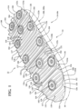
FIG. 1 is a perspective view of an outsole for an article of footwear in accordance with principles of the present disclosure; -
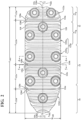
FIG. 2 is a bottom plan view of the outsole ofFIG. 1 ; -
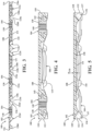
FIG. 3 is a cross-sectional view of the outsole ofFIG. 1 , taken along section line 3-3 inFIG. 2 ; -
FIG. 4 is a cross-sectional view of the outsole ofFIG. 1 , taken along section line 4-4 inFIG. 2 ; -
FIG. 5 is a cross-sectional view of the outsole ofFIG. 1 , taken along section line 5-5 inFIG. 2 ; -
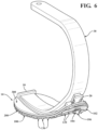
FIG. 6 is a perspective view of an article of footwear in accordance with principles of the present disclosure shown in conjunction with a prosthetic blade; -
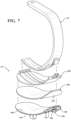
FIG. 7 is an exploded perspective view of the article of footwear ofFIG. 6 ; -
FIG. 8 is a perspective view of an article of footwear in accordance with principles of the present disclosure; -
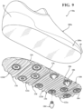
FIG. 9 is an exploded perspective view of the article of footwear ofFIG. 8 ; -
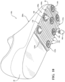
FIG. 10 is a perspective view of an article of footwear in accordance with principles of the present disclosure; and -
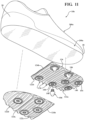
FIG. 11 is an exploded perspective view of the article of footwear ofFIG. 10 . - Corresponding reference numerals indicate corresponding parts throughout the drawings.
- Example configurations will now be described more fully with reference to the accompanying drawings. Example configurations are provided so that this disclosure will be thorough, and will fully convey the scope of the disclosure to those of ordinary skill in the art. Specific details are set forth such as examples of specific components, devices, and methods, to provide a thorough understanding of configurations of the present disclosure. It will be apparent to those of ordinary skill in the art that specific details need not be employed, that example configurations may be embodied in many different forms, and that the specific details and the example configurations should not be construed to limit the scope of the disclosure.
- The terminology used herein is for the purpose of describing particular exemplary configurations only and is not intended to be limiting. As used herein, the singular articles "a," "an," and "the" may be intended to include the plural forms as well, unless the context clearly indicates otherwise. The terms "comprises," "comprising," "including," and "having," are inclusive and therefore specify the presence of features, steps, operations, elements, and/or components, but do not preclude the presence or addition of one or more other features, steps, operations, elements, components, and/or groups thereof. The method steps, processes, and operations described herein are not to be construed as necessarily requiring their performance in the particular order discussed or illustrated, unless specifically identified as an order of performance. Additional or alternative steps may be employed.
- When an element or layer is referred to as being "on," "engaged to," "connected to," "attached to," or "coupled to" another element or layer, it may be directly on, engaged, connected, attached, or coupled to the other element or layer, or intervening elements or layers may be present. In contrast, when an element is referred to as being "directly on," "directly engaged to," "directly connected to," "directly attached to," or "directly coupled to" another element or layer, there may be no intervening elements or layers present. Other words used to describe the relationship between elements should be interpreted in a like fashion (e.g., "between" versus "directly between," "adjacent" versus "directly adjacent," etc.). As used herein, the term "and/or" includes any and all combinations of one or more of the associated listed items.
- The terms first, second, third, etc. may be used herein to describe various elements, components, regions, layers and/or sections. These elements, components, regions, layers and/or sections should not be limited by these terms. These terms may be only used to distinguish one element, component, region, layer or section from another region, layer or section. Terms such as "first," "second," and other numerical terms do not imply a sequence or order unless clearly indicated by the context. Thus, a first element, component, region, layer or section discussed below could be termed a second element, component, region, layer or section without departing from the teachings of the example configurations.
- One aspect of the disclosure provides an outsole for an article of footwear, the outsole including a main body having a plurality of modules arranged in series from a first end to a second end, adjacent ones of the modules detachably connected to each other along one of a plurality of seams extending from a first side of the main body to a second side of the main body. The outsole further including at least one insert embedded in each of the modules and configured for selectively attaching a traction element to the outsole.
- The outsole may include one or more of the following optional features. Namely, each of the modules may include a plurality of ribs extending from a first terminal end at the first side of the main body to a second terminal end at the second side of the main body. The main body may include a top side and a bottom side formed on an opposite side of the main body from the top side, the plurality of ribs being formed on the bottom side of the main body. At least one of the first terminal end and the second terminal end may be flat and may extend perpendicular to the top side of the main body.
- In one configuration, at least one of the plurality of ribs of each of the modules may include a first traction element formed at the first terminal end and a second traction element formed at the second terminal end. The at least one of the plurality of the ribs may be disposed at a first end of each of the modules, adjacent to one of the plurality of seams.
- The plurality of ribs of each of the modules may include a first rib disposed at a first end of each module and a second rib disposed at a second end of each module, the first rib including a first traction element disposed at the first side and a second traction element disposed at the second side and the second rib including a third traction element disposed at the first side and a fourth traction element disposed at the second side.
- In one configuration, the plurality of modules may include (i) a first module formed at a first end of the main body and having a first length, (ii) a second module detachably connected to the first module along a first one of the plurality of seams and having a second length, and (iii) a third module detachably connected to the second module along a second one of the plurality of seams and having a third length. At least one of the first length, the second length, and the third length may be different than the other of the first length, the second length, and the third length. Additionally or alternatively, the second module may include a first portion having a first plurality of the inserts and a second portion having a second plurality of the inserts, the first portion isolated from the second portion by a series of ribs.
- In another aspect of the disclosure, an article of footwear is provided and includes a midsole having a bottom surface and an outsole attached to the bottom surface of the midsole and including a main body having a series of modules each including at least one insert configured for selectively attaching a traction element to the outsole, adjacent ones of the modules detachably connected to each other along one of a plurality of seams extending from a first side of the main body to a second side of the main body.
- This aspect of the disclosure may include one or more of the following optional features. For example, each of the modules may include a plurality of ribs each extending from a first terminal end at the first side of the main body to a second terminal end at the second side of the main body. The main body may include a top side and a bottom side formed on an opposite side of the main body from the top side, the plurality of ribs being formed on the bottom side of the main body. At least one of the first terminal end and the second terminal end may be flat and may extend perpendicular to the top side of the main body.
- In one configuration, at least one of the plurality of ribs of each of the modules may include a first traction element formed at the first terminal end and a second traction element formed at the second terminal end. Additionally or alternatively, the at least one of the plurality of the ribs may be disposed at a first end of each of the modules, adjacent to one of the plurality of seams.
- The plurality of ribs of each of the modules may include a first rib disposed at a first end of each module and a second rib disposed at a second end of each module, the first rib including a first traction element disposed at the first side and a second traction element disposed at the second side and the second rib including a third traction element disposed at the first side and a fourth traction element disposed at the second side.
- In one configuration, the series of modules may include (i) a first module formed at a first end of the main body and having a first length, (ii) a second module detachably connected to the first module along a first one of the plurality of seams and having a second length, and (iii) a third module detachably connected to the second module along a second one of the plurality of seams and having a third length. At least one of the first length, the second length, and the third length may be different than the other of the first length, the second length, and the third length.
- The second module may include a first portion having a first plurality of the inserts and a second portion having a second plurality of the inserts, the first portion isolated from the second portion by a series of ribs.
- In one configuration, the bottom surface of the midsole may be curved along a direction from an anterior end to a posterior end. Additionally or alternatively, at least a portion of the bottom surface of the midsole is flat.
- The details of one or more implementations of the disclosure are set forth in the accompanying drawings and the description below. Other aspects, features, and advantages will be apparent from the description, the drawings, and the claims.
- Referring to
FIGS. 1-4 , anoutsole 100 for an article of footwear 10-10b is provided. In some instances, theoutsole 100 is provided as a standalone component that can be modified prior to attachment to the article of footwear 10-10b depending on the type of footwear and/or the intended use. As described below with respect toFIGS. 6-11 , theoutsole 100 may be used in conjunction with a prosthesis such as aprosthetic blade 30 or with a conventional article offootwear prosthetic blade 30 may include a different size and/or shape when used in conjunction with aprosthetic blade 30 as compared to the size and/or shape of theoutsole 100 when used in conjunction with the articles offootwear - While
FIGS. 1-4 are directed towards theoutsole 100, features and elements of theoutsole 100 may be described relative to theprosthetic blade 30 or the articles offootwear 10a-10b (shown in phantom) to which theoutsole 100 may be attached. Particularly, elements and features of theoutsole 100 may be described relative to aforefoot region 12, amid-foot region 14, and aheel region 16 of theprosthetic blade 30 or the articles offootwear 10a-10b. - The
forefoot region 12 may include atoe portion 12T corresponding with toes, and aball portion 12B corresponding with joints connecting metatarsal bones with phalanx bones of a foot. Themid-foot region 14 may correspond with an arch area of the foot, and theheel region 16 may correspond with rear portions of the foot, including a calcaneus bone. Additionally, theoutsole 100 may be described relative to ananterior end 18 formed at a foremost portion of theforefoot region 12 and aposterior end 20 formed at a rearmost portion of theheel region 16. Lateral andmedial sides footwear 10a-10b correspond to lateral and medial sides of a respective leg or foot to which the articles offootwear 10a-10b are attached. Likewise, lateral andmedial sides prosthetic blade 30 correspond to lateral and medial sides of a respective leg to which theprosthetic blade 30 is attached. - With reference to
FIG. 1 , theoutsole 100 includes amain body 102 and a plurality ofinserts 104 disposed within themain body 102. Theinserts 104 are each configured for selectively attaching a traction element 106 (FIGS. 6-11 ), such as a stud or cleat, to theoutsole 100. Themain body 102 may be formed of an elastomeric material, while theinserts 104 are formed of a second material having a greater hardness than the first material. In some examples, the first material is a polyether block amide (PEBA), such as PEBAX® Brand elastomers produced by Arkema S.A. Theinserts 104 may be formed of any material suitable for engaging and supporting thestuds 106, such as a metal. - Referring to
FIGS. 1-4 , themain body 102 may be described as including atop side 108, abottom side 110 formed on an opposite side than thetop side 108, and aperipheral side 112 extending from thetop side 108 to thebottom side 110 and defining an outer peripheral profile of themain body 102 and theoutsole 100. Generally, thetop side 108 includes a continuous smooth surface and is configured to attach to theprosthetic blade 30 or the article offootwear 10a-10b, as discussed below. In some instances, thetop side 108 is provided with one or more adhesives for bonding thetop side 108 to a corresponding surface on a bottom of theprosthetic blade 30 or the article offootwear 10a-10b. Optionally, theoutsole 100 may include a pre-applied adhesive covered by a removable sheet, such that a user can remove and discard the sheet to expose the adhesive immediately before attaching theoutsole 100 to theprosthetic blade 30 or the article offootwear 10a-10b. Thebottom side 110 is configured to engage a ground surface and includes one or more traction elements for providing traction, as described in greater detail below. - As shown in
FIG. 2 , a length L102 of themain body 102 extends along a longitudinal axis A102 from afirst end 114 to asecond end 116. As described in greater detail below, when attached to one of the articles offootwear 10a-10b or theprosthetic blade 30, thefirst end 114 is configured to be disposed in theforefoot region 12 at theanterior end 18 of the article of footwear or blade, and thesecond end 116 is configured to be disposed in theheel region 16 at theposterior end 20. Accordingly, the first and second ends 114, 116 may also be referred to as anterior and posterior ends 114, 116 of themain body 102, respectively. - A width W102 of the
main body 102 extends perpendicular to the longitudinal axis A102 from afirst side 118 to asecond side 120. When theoutsole 100 is attached to the article offootwear 10a-10b or theprosthetic blade 30, thefirst side 118 is configured to be disposed along alateral side 22 of thefootwear 10a-10b orblade 30 and thesecond side 120 is configured to be disposed along amedial side 24 of thefootwear 10a-10b orblade 30. Accordingly, the first andsecond sides medial sides main body 102 is configured to extend entirely across a width of the article offootwear 10a-10b orprosthetic blade 30. While thesides outsole 100 has a constant width W102, one or both of the sides may have a contour corresponding to an outer profile of a foot. - With continued reference to
FIGS. 1-4 , themain body 102 includes a plurality ofmodules 122a-122d arranged in series, whereby adjacent ones of themodules 122a-122d are attached to each other alongrespective seams 124a-124c. As shown inFIGS. 1-3 , themain body 102 includes afirst module 122a disposed at thefirst end 114 of themain body 102, asecond module 122b connected to thefirst module 122a along afirst seam 124a, athird module 122c connected to thesecond module 122b along asecond seam 124b, and afourth module 122d disposed at thesecond end 120 of themain body 102 and connected to thethird module 122c along athird seam 124c. - With reference to the cross-sectional view of
FIG. 3 , each of theseams 124a-124c is formed by a portion of themain body 102 having a reduced thickness relative to the adjoining portions of themodules 122a-122d. Theseams 124a-124c extend continuously from thefirst side 118 to thesecond side 120. Optionally, the seams may include perforations formed therethrough (not shown). Accordingly, theseams 124a-124c are configured to function as tear, cut, or break lines along which adjacent ones of themodules 122a-122d can be separated from each other to modify the overall length L102 of themain body 102. For instance, any one or more of themodules 122a-122d may be separated from one or more of theother modules 122a-122d along one of theseams 124a-124c. As discussed below, this may be done in situations where a shortened portion of theoutsole 100 is desired for attachment to the article offootwear 10a-10b or theprosthetic blade 30. Additionally, theseams 124a-124c may function to allow theoutsole 100 to flex along the longitudinal axis A102 to accommodate curved implementations (e.g.,FIGS. 5 and6 ) or bending of theoutsole 100 during use. - Lengths L122a-L122d of each of the
modules 122a-122d extend from a respective first end 126a-126d facing thefirst end 114 of themain body 102, to a respectivesecond end 128a-128d facing thesecond end 116 of themain body 102. Eachmodule 122a-122d includes a respective series of laterally-extending (i.e., side-to-side)ribs 130 spaced along the length L122a-L122d of thebottom side 110 of themodule 122a-122d, from the first end 126a-126d to thesecond end 128a-128d. In the illustrated example, theribs 130 are evenly and continuously spaced from the first end 126a-126d to the second end 126a-126d. - One or more of the
ribs 130 may extend from a firstterminal end 132 at thefirst side 118 of themain body 102 to a secondterminal end 134 at thesecond side 120 of themain body 102. In some instances, one or more of theribs 130 extends continuously from the firstterminal end 132 to the secondterminal end 134, while in other instances, some of theribs 130 may be interrupted by one or more of theinserts 104. As best shown inFIG. 3 , each of theribs 130 has a triangular cross-sectional shape, such that each rib extends from a base portion having a first width at thebottom side 110, to adistal edge 131 facing away from thebottom side 110. Here, the bases of adjacent ones of theribs 130 are connected to each other along the lengths of theribs 130 from thefirst side 118 to thesecond side 120. The sharpdistal edges 131 of theribs 130 may function as traction elements. - As described in greater detail below with respect to individual ones of the
modules 122a-122d, themain body 102 may include a plurality ofcleats 136 formed along each of thesides cleats 136 is integrally formed as a portion of one of the terminal ends 132, 134 of one of theribs 130. Particularly, one of thecleats 136 may be formed at both terminal ends 132, 134 of one or more of theribs 130. Here, the terminal ends 132, 134 formed by thecleats 136 are formed flush with theperipheral side 112 of themain body 102, and are substantially perpendicular (90 degrees ± 5 degrees) to the top side 108 (FIG. 5 ). - As best shown in
FIG. 5 , an intermediate portion of each of theribs 130 has a substantially constant height H130 between the firstterminal end 132 and the secondterminal end 134. Where thecleats 136 are included, the heights H130 of theribs 130 flare at eachterminal end distal tip 137 that protrudes from thebottom side 110 of themain body 102. Additionally, each of thecleats 136 may widen and/or curve along a direction of the longitudinal axis A102. For example, thecleats 136 may widen or curve around one of theinserts 104 adjacent to theterminal end rib 130. In some instances, this results in thecleats 136 formed on ribs at the first end 126a-126d and thesecond end 128a-128d curving away from the respective end 126a-126d, 128a-128d along which it is disposed. Thus, thecleats 136 disposed at opposite ends of amodule 122a-122d will curve towards each other along theside main body 102. - Generally, each of the
modules 122a-122d includescleats 136 formed on the terminal ends 132, 134 of theribs 130 disposed at the first end 126a-126d and thesecond end 128a-128, such that eachmodule 122a-122d is bookended by a pair of theribs 130 including thecleats 136. Thus, regardless of where themodules 122a-122d are separated from each other, the remainingmodules 122a-122d that are attached to the article offootwear 10a-10b or theprosthetic blade 30 will include thecleats 136 disposed at least at each end 126a-126d, 128a-128d. Optionally, one or moreintermediate ribs 130 may also includecleats 136, as discussed below. - With continued reference to
FIGS. 1 and2 , each of themodules 122a-122d includes one or more of theinserts 104 configured for selectively attaching a cleat orstud 106 to theoutsole 100. In the illustrated example, each of theinserts 104 includes a helically-threadedaperture 140 configured for interfacing with a corresponding threaded shank of astud 106. In other examples, theinsert 104 may have other means for attaching to thestud 106. As provided above, each of theinserts 104 may be embedded within the material of themain body 102 during a molding process. As shown inFIG. 4 , theinserts 104 include radially extendingflanges 142 that are embedded in the material of themain body 102. Optionally, themain body 102 may be pre-molded with a plurality ofsockets 138 within which theinserts 104 are disposed. In some examples, theinserts 104 may be placed into thesockets 138 after molding themain body 102 and attached using mechanical or chemical fastening means. - As best shown in
FIG. 2 , theinserts 104 are arranged along thebottom side 110 of themain body 102 in a manner that allows the outsole to flex along theribs 130. Particularly, all of theinserts 104 are contained within themodules 122a-122d (i.e., disposed between the first ends 126a-126d and thesecond ends 128a-128d), such that theseams 124a-124c are uninterrupted. Thus, themain body 102 can freely flex at each of theseams 124a-124c. Additionally, theinserts 104 may be provided as laterally-aligned pairs disposed onopposite sides main body 102, where adjacent pairs of theinserts 104 are longitudinally separated from each other by a series of theribs 130 such that theribs 130 allow themain body 102 to bend in intermediate portions of themodules 122a-122d between the pairs of theinserts 104. - Referring now to
FIGS. 1-3 , thefirst module 122a is configured to be disposed adjacent to ananterior end 18 of the article offootwear 10a-10b orprosthetic blade 30. As shown, a first end 126a of thefirst module 122a is coincident with thefirst end 114 of themain body 102, and thesecond end 128a is disposed in an intermediate portion of themain body 102. A length L122a of thefirst module 122a corresponds to lengths of the toes of a foot, such that when theoutsole 100 is incorporated in an article offootwear 10a-10b, thefirst seam 124a allows thefirst module 122a to flex with the toes. As shown, the first end 126a of thefirst module 122a may be arcuate, such that the first end 126a curves continuously around themain body 102 and converges with thesecond end 128a on eachside first module 122a includes a laterally-aligned pair of theinserts 104 disposed between the first end 126a and thesecond end 128a. As shown, one of theribs 130 disposed along thesecond end 128a includes a pair of thecleats 136, which each widen and curve towards the first end 126a. - With continued reference to
FIGS. 1-3 , a length L122b of thesecond module 122b extends from afirst end 126b attached to thefirst module 122a along thefirst seam 124a to asecond end 128b associated with amid-foot region 14 of the article offootwear 10a-10b orprosthetic blade 30. The length L122b of thesecond module 122b is greater than the length L122a of thefirst module 122a. Here, thesecond module 122b may be described as including a first portion 122bi configured to be disposed in theball portion 12B of the article offootwear 10a-10b orprosthetic blade 30, and asecond portion 122b2 configured to be disposed in an anterior end of themid-foot region 14 of the article offootwear 10a-10b orprosthetic blade 30. Thefirst portion 122b1 of thesecond module 122b includes a first set ofinserts 104 that are isolated from a second set ofinserts 104 of thesecond portion 122b2 by a plurality of theribs 130. The first set ofinserts 104 is disposed adjacent to thefirst end 126b and includes acentral insert 104 at thefirst end 126b and a laterally-aligned pair of theinserts 104 spaced apart from thefirst end 126b, such that the first set ofinserts 104 are arranged in a triangular pattern. Thesecond portion 122b2 includes a second set ofinserts 104 including a laterally-aligned pair of theinserts 104 disposed adjacent to thesecond end 128b. By isolating the first set ofinserts 104 from the second set ofinserts 104, thesecond module 122d can more easily flex along the intermediate portion. - As discussed above, the
second module 122b includes afirst rib 130 disposed at thefirst end 126b and asecond rib 130 disposed at thesecond end 128b, where each of thefirst rib 130 and thesecond rib 130 includes a pair of thecleats 136 formed at the respective terminal ends 132, 134 of therib 130. As shown, thecleats 136 of the first andsecond ribs 130 widen and curve around adjacent ones of theinserts 104 and towards an intermediate portion of thesecond module 122b. Additionally, thesecond module 122b includes the series ofribs 130 arranged between the first and second sets ofinserts 104, where each of theribs 130 of the series includes thecleats 136 formed at the respective terminal ends 132, 134. Here, the one ormore ribs 130 closest to thefirst portion 122b1 havecleats 136 that widen and curve towards thefirst portion 122b1, the one ormore ribs 130 closest to thesecond portion 122b2 includecleats 136 that widen and curve towards thesecond portion 122b2, and the one or more ribs disposed between thefirst portion 122b1 and thesecond portion 122b2 have cleats that widen and curve towards each of thefirst portion 122b1 and thesecond portion 122b2. - Referring still to
FIGS. 1-3 , a length L122c of thethird module 122c extends from afirst end 126c attached to thesecond module 122b along thesecond seam 124b in themid-foot region 14, to asecond end 128c adjacent to a portion of theoutsole 100 corresponding to aheel region 16 of the article offootwear 10a-10b orprosthetic blade 30. The length L122c of thethird module 122c is greater than the length L122a of thefirst module 122a and less than the length L122b of thesecond module 122b. Thethird module 122c includes a third set ofinserts 104 disposed between thefirst end 126c and thesecond end 128c, which includes acentral insert 104 at thefirst end 126b and a laterally-aligned pair of theinserts 104 at thesecond end 128c, such that the third set ofinserts 104 includes a triangular pattern. - The
third module 122c includes afirst rib 130 at thefirst end 126c and asecond rib 130 at thesecond end 128c, where each of thefirst rib 130 and thesecond rib 130 includes a pair of thecleats 136 formed at the respective terminal ends 132, 134 of therib 130. As shown, thecleats 136 of the first andsecond ribs 130 widen and curve around adjacent ones of theinserts 104 and towards an intermediate portion of thethird module 122c. Thethird module 122c may further include anintermediate rib 130 that is interrupted by thecentral insert 104 and includes thecleats 136 located at eachterminal end - The
fourth module 122d includes afirst end 126d attached to thesecond end 128c of thethird module 122c along thethird seam 124c, and a second end 128d disposed adjacent to thesecond end 116 of themain body 102. Accordingly, a length L122d of thefourth module 122d is configured to extend along theheel region 16 of the article offootwear 10a-10b orprosthetic blade 30. The length L122cd of thefourth module 122d is substantially similar to the length L122c of thethird module 122c. Thefourth module 122d includes aninsert 104 disposed in a central portion, between the first andsecond sides main body 102. - The
fourth module 122d includes afirst rib 130 at thefirst end 126d and asecond rib 130 at the second end 128d. In the illustrated example, where the second end 128d is curved or arcuate from thefirst side 118 to thesecond side 120, therib 130 at the second end 128d may be substantially straight such that an intermediate portion of therib 130 is spaced apart from the second end 128d. Each of thefirst rib 130 and thesecond rib 130 includes a pair of thecleats 136 formed at the respective terminal ends 132, 134 therib 130. As shown, thecleats 136 of the first andsecond ribs 130 widen and curve towards an intermediate portion of thefourth module 122d. - Referring now to
FIGS. 6 and7 , theoutsole 100 is shown in conjunction with theprosthetic blade 30. In some examples, theoutsole 100 may be attached directly to a bottom surface of theprosthetic blade 30, where the width W102 of themain body 102 is substantially the same as a width of theprosthetic blade 30 such that theoutsole 100 is fully attached along the bottom of theprosthetic blade 30 to provide theblade 30 with traction elements. - Optionally, and as shown in
FIGS. 6 and7 , theoutsole 100 may be incorporated onto theprosthetic blade 30 using a detachableprosthetic foot 10. Here, theprosthetic foot 10 includes amidsole 200 providing one or more layers for cushioning and ground engagement, and achassis 300 configured for securing theprosthetic foot 10 to theblade 30. As discussed above, theprosthetic foot 10 extends from ananterior end 18 to aposterior end 20. - The
midsole 200 is attached to a lower portion of thechassis 300 and includes a bottom surface 202 formed on an opposite side of themidsole 200 from thechassis 300. As shown, at least a portion of the bottom surface 202 may be convex along a direction from theanterior end 18 to theposterior end 20. Thus, the bottom surface 202 is configured to provide continuous engagement between theprosthetic foot 10 and the ground surface as theprosthetic foot 10 rolls forward over the ground surface during running or walking. - In use, the
outsole 100 is configured to be attached to the bottom surface 202 of themidsole 200 to provide theprosthetic foot 10 with a resilient ground-engaging surface including thetraction elements outsole 100 may initially be provided in a unitary state, where each of themodules 122a-122d are attached to each other along therespective seams 124a-124c. In the illustrated example, theoutsole 100 is attached to themidsole 200 in the unitary state such that theoutsole 100 extends continuously from theanterior end 18 to theposterior end 20. Here, theribs 130 and theseams 124a-124c of theoutsole 100 allow theoutsole 100 to bend continuously along the convex bottom surface 202 of themidsole 200 such that theoutsole 100 will mold to the profile of the bottom surface 202. Accordingly, when attached to themidsole 200, thebottom side 110 of theoutsole 100 will also be convex. - While the
outsole 100 of the illustrated example is shown in a unitary state, theoutsole 100 of the present disclosure allows for one or more of themodules 122a-122d to be detached from theoutsole 100 prior to or after attachment of theoutsole 100 to themidsole 200. For example, theoutsole 100 may be separated along any one or more of theseams 124a-124c so that one or more of themodules 122a-122d can be attached to a corresponding portion of themidsole 200 to provide themidsole 200 with theinserts 104. - With particular reference to
FIGS. 8 and9 , an article offootwear 10a is provided and includes theoutsole 100, amidsole 200a, and achassis 300a. Here, the article offootwear 10a is embodied as a conventional shoe, where thechassis 300a is an upper 300a configured for securing a foot of a user to themidsole 200a. The upper 300a is attached to themidsole 200a and includes interior surfaces that define an interior void configured to receive and secure a foot for support on themidsole 200a. The upper 300a may be formed from one or more materials that are stitched or adhesively bonded together to form the interior void. Suitable materials of the upper 300 may include, but are not limited to, mesh, textiles, foam, leather, and synthetic leather. The materials may be selected and located to impart properties of durability, air-permeability, wear-resistance, flexibility, and comfort. - In use, the
outsole 100 may be initially provided in a unitary state, as shown inFIG. 9 . Thetop side 108 of themain body 102 is then prepared for attachment to the bottom surface 202 of themidsole 200a, either by removing a cover sheet from thetop side 108 to expose a pre-applied adhesive, or by applying an adhesive to thetop side 108 and/or the bottom surface 202. Theoutsole 100 is then positioned on the bottom surface 202 of themidsole 200a so that thefirst module 122a is positioned at theanterior end 18 and thefourth module 122d is positioned at theposterior end 20, with the first andsecond sides medial sides outsole 100 may be attached to themidsole 200a during manufacturing of the article offootwear 10a in a conventional fashion by bonding theoutsole 100 to themidsole 200a using a suitable adhesive. - Unlike the
midsole 200 discussed above with respect to theprosthetic foot 10, the bottom surface 202 of themidsole 200a of the article offootwear 10a may be substantially flat, including slight curvatures at the anterior and posterior ends 18, 20 to accommodate the natural motion of the foot during walking and running. Accordingly, when theoutsole 100 is attached to the bottom surface 202 of themidsole 200a, the first andfourth modules third seams third modules midsole 200a. However, in instances where themidsole 200a includes contours along the intermediate portion, theribs 130 of second andthird modules third modules - With particular reference to
FIGS. 10 and11 , an article offootwear 10b is provided and includes theoutsole 100a, themidsole 200a, and thechassis 300a. In this example, theoutsole 100a is separated along thesecond seam 124b and the third andfourth modules first module 122a and thesecond module 122b are attached to the bottom surface 202 of the midsole 200a adjacent to theanterior end 18. - The following Clauses provide an exemplary configuration for a sole structure for an article of footwear or a prosthetic blade, as described above.
- Clause 1: An outsole for an article of footwear, the outsole including: a main body including a plurality of modules arranged in series from a first end to a second end, adjacent ones of the modules detachably connected to each other along one of a plurality of seams extending from a first side of the main body to a second side of the main body; and at least one insert embedded in each of the modules and configured for selectively attaching a traction element to the outsole.
- Clause 2: The outsole of Clause 1, wherein each of the modules includes a plurality of ribs extending from a first terminal end at the first side of the main body to a second terminal end at the second side of the main body.
- Clause 3: The outsole of Clause 2, wherein the main body includes a top side and a bottom side formed on an opposite side of the main body from the top side, the plurality of ribs being formed on the bottom side of the main body.
- Clause 4: The outsole of
Clause 3, wherein at least one of the first terminal end and the second terminal end is flat and extends perpendicular to the top side of the main body. - Clause 5: The outsole of any one of Clauses 2-4, wherein at least one of the plurality of ribs of each of the modules includes a first traction element formed at the first terminal end and a second traction element formed at the second terminal end.
- Clause 6: The outsole of
Clause 5, wherein the at least one of the plurality of the ribs is disposed at a first end of each of the modules, adjacent to one of the plurality of seams. - Clause 7: The outsole of Clause 2, wherein the plurality of ribs of each of the modules includes a first rib disposed at a first end of each module and a second rib disposed at a second end of each module, the first rib including a first traction element disposed at the first side and a second traction element disposed at the second side and the second rib including a third traction element disposed at the first side and a fourth traction element disposed at the second side.
- Clause 8: The outsole of any one of the preceding clauses, wherein the plurality of modules includes (i) a first module formed at a first end of the main body and having a first length, (ii) a second module detachably connected to the first module along a first one of the plurality of seams and having a second length, and (iii) a third module detachably connected to the second module along a second one of the plurality of seams and having a third length.
- Clause 9: The outsole of Clause 8, wherein at least one of the first length, the second length, and the third length is different than the other of the first length, the second length, and the third length.
- Clause 10: The outsole of any one of Clauses 8 or 9, wherein the second module includes a first portion having a first plurality of the inserts and a second portion having a second plurality of the inserts, the first portion isolated from the second portion by a series of ribs.
- Clause 11: An article of footwear including: a midsole having a bottom surface; and an outsole attached to the bottom surface of the midsole and including a main body having a series of modules each including at least one insert configured for selectively attaching a traction element to the outsole, adjacent ones of the modules detachably connected to each other along one of a plurality of seams extending from a first side of the main body to a second side of the main body.
- Clause 12: The article of footwear of
Clause 11, wherein each of the modules includes a plurality of ribs each extending from a first terminal end at the first side of the main body to a second terminal end at the second side of the main body. - Clause 13: The article of footwear of
Clause 12, wherein the main body includes a top side and a bottom side formed on an opposite side of the main body from the top side, the plurality of ribs being formed on the bottom side of the main body. - Clause 14: The article of footwear of Clause 13, wherein at least one of the first terminal end and the second terminal end is flat and extends perpendicular to the top side of the main body.
- Clause 15: The article of footwear of any one of Clauses 12-14, wherein at least one of the plurality of ribs of each of the modules includes a first traction element formed at the first terminal end and a second traction element formed at the second terminal end.
- Clause 16: The article of footwear of Clause 15, wherein the at least one of the plurality of the ribs is disposed at a first end of each of the modules, adj acent to one of the plurality of seams.
- Clause 17: The article of footwear of
Clause 12, wherein the plurality of ribs of each of the modules includes a first rib disposed at a first end of each module and a second rib disposed at a second end of each module, the first rib including a first traction element disposed at the first side and a second traction element disposed at the second side and the second rib including a third traction element disposed at the first side and a fourth traction element disposed at the second side. - Clause 18: The article of footwear of any one of Clauses 11-17, wherein the series of modules includes (i) a first module formed at a first end of the main body and having a first length, (ii) a second module detachably connected to the first module along a first one of the plurality of seams and having a second length, and (iii) a third module detachably connected to the second module along a second one of the plurality of seams and having a third length.
- Clause 19: The article of footwear of
Clause 18, wherein at least one of the first length, the second length, and the third length is different than the other of the first length, the second length, and the third length. - Clause 20: The article of footwear of any one of
Clauses 18 or 19, wherein the second module includes a first portion having a first plurality of the inserts and a second portion having a second plurality of the inserts, the first portion isolated from the second portion by a series of ribs. - Clause 21: The article of footwear of any one of Clauses 11-20, wherein the bottom surface of the midsole is curved along a direction from an anterior end to a posterior end.
- Clause 22: The article of footwear of any one of Clauses 11-20, wherein at least a portion of the bottom surface of the midsole is flat.
- The foregoing description has been provided for purposes of illustration and description. It is not intended to be exhaustive or to limit the disclosure. Individual elements or features of a particular configuration are generally not limited to that particular configuration, but, where applicable, are interchangeable and can be used in a selected configuration, even if not specifically shown or described. The same may also be varied in many ways. Such variations are not to be regarded as a departure from the disclosure, and all such modifications are intended to be included within the scope of the disclosure.
- THE FOLLOWING ITEMS DESCRIBE FURTHER ASPECTS, FEATURES AND EMBODIMENTS OF THE ITEMED INVENTION:
- 1. An outsole for an article of footwear, the outsole comprising:
- a main body including a plurality of modules arranged in series from a first end to a second end, adjacent ones of the modules detachably connected to each other along one of a plurality of seams extending from a first side of the main body to a second side of the main body; and
- at least one insert embedded in each of the modules and configured for selectively attaching a traction element to the outsole.
- 2. The outsole of Item 1, wherein each of the modules includes a plurality of ribs extending from a first terminal end at the first side of the main body to a second terminal end at the second side of the main body.
- 3. The outsole of Item 2, wherein the main body includes a top side and a bottom side formed on an opposite side of the main body from the top side, the plurality of ribs being formed on the bottom side of the main body.
- 4. The outsole of
Item 3, wherein at least one of the first terminal end and the second terminal end is flat and extends perpendicular to the top side of the main body. - 5. The outsole of any of Items 2-4, wherein at least one of the plurality of ribs of each of the modules includes a first traction element formed at the first terminal end and a second traction element formed at the second terminal end.
- 6. The outsole of
Item 5, wherein the at least one of the plurality of the ribs is disposed at a first end of each of the modules, adjacent to one of the plurality of seams. - 7. The outsole of Item 2, wherein the plurality of ribs of each of the modules includes a first rib disposed at a first end of each module and a second rib disposed at a second end of each module, the first rib including a first traction element disposed at the first side and a second traction element disposed at the second side and the second rib including a third traction element disposed at the first side and a fourth traction element disposed at the second side.
- 8. The outsole of any of the preceding items, wherein the plurality of modules includes (i) a first module formed at a first end of the main body and having a first length, (ii) a second module detachably connected to the first module along a first one of the plurality of seams and having a second length, and (iii) a third module detachably connected to the second module along a second one of the plurality of seams and having a third length.
- 9. The outsole of Item 8, wherein at least one of the first length, the second length, and the third length is different than the other of the first length, the second length, and the third length.
- 10. The outsole of Item 8 or Item 9, wherein the second module includes a first portion having a first plurality of the inserts and a second portion having a second plurality of the inserts, the first portion isolated from the second portion by a series of ribs.
- 11. An article of footwear comprising:
- a midsole having a bottom surface; and
- an outsole attached to the bottom surface of the midsole and including a main body having a series of modules each including at least one insert configured for selectively attaching a traction element to the outsole, adjacent ones of the modules detachably connected to each other along one of a plurality of seams extending from a first side of the main body to a second side of the main body.
- 12. The article of footwear of
Item 11, wherein each of the modules includes a plurality of ribs each extending from a first terminal end at the first side of the main body to a second terminal end at the second side of the main body. - 13. The article of footwear of
Item 12, wherein the main body includes a top side and a bottom side formed on an opposite side of the main body from the top side, the plurality of ribs being formed on the bottom side of the main body. - 14. The article of footwear of Item 13, wherein at least one of the first terminal end and the second terminal end is flat and extends perpendicular to the top side of the main body.
- 15. The article of footwear of any of Items 12-14, wherein at least one of the plurality of ribs of each of the modules includes a first traction element formed at the first terminal end and a second traction element formed at the second terminal end.
- 16. The article of footwear of Item 15, wherein the at least one of the plurality of the ribs is disposed at a first end of each of the modules, adjacent to one of the plurality of seams.
- 17. The article of footwear of
Item 12, wherein the plurality of ribs of each of the modules includes a first rib disposed at a first end of each module and a second rib disposed at a second end of each module, the first rib including a first traction element disposed at the first side and a second traction element disposed at the second side and the second rib including a third traction element disposed at the first side and a fourth traction element disposed at the second side. - 18. The article of footwear of any of Items 11-17, wherein the series of modules includes (i) a first module formed at a first end of the main body and having a first length, (ii) a second module detachably connected to the first module along a first one of the plurality of seams and having a second length, and (iii) a third module detachably connected to the second module along a second one of the plurality of seams and having a third length.
- 19. The article of footwear of
Item 18, wherein at least one of the first length, the second length, and the third length is different than the other of the first length, the second length, and the third length. - 20. The article of footwear of
Item 18 or Item 19, wherein the second module includes a first portion having a first plurality of the inserts and a second portion having a second plurality of the inserts, the first portion isolated from the second portion by a series of ribs. - 21. The article of footwear of any of Items 11-20, wherein the bottom surface of the midsole is curved along a direction from an anterior end to a posterior end.
- 22. The article of footwear of any of Items 11-20, wherein at least a portion of the bottom surface of the midsole is flat.
Claims (15)
- An outsole (100) for an article of footwear (10a, 10b), the outsole (100) comprising:a main body (102) having a width (W102) extending from a first side (118) to a second side (120) and including a first module (122a) and a second module (122b) arranged in series between a first anterior end (114) of the outsole (100) and a second posterior end (116) of the outsole (100),the first module (122a) and the second module (122b) each having a length (L122a, L122b) extending from a first end (126a, 126b) including a first rib (130) to a second end (128a, 128b) including a second rib (130),the first end (126a, 126b) of the first module (122a) connected to the second end (128a, 128b) of the second module (122b) along a seam (124a) formed by a portion of the main body (102) having a reduced thickness relative to adjoining portions of the first module (122a) and the second module (122b) and extending continuously from the first side (118) to the second side (120) of the main body,each of the ribs (130) extending continuously from a first terminal end (132) to a second terminal end (134),the main body (102) including a first cleat (136) and a second cleat (136) formed on the ribs (130) at the first end (126a, 126b) and the second end (128a, 128b); andat least one insert (104) embedded in each of the first module (122a) and the second module (122b) and configured for selectively attaching a traction element (106) to the outsole (100).
- The outsole of Claim 1, wherein the first terminal end (132) formed by the first cleat (136) of each rib (130) is formed flush with the first side (118) of the main body (102) and the second terminal end (134) of the second cleat (136) of each rib (130) is formed flush with the second side (120) of the main body (102).
- The outsole of Claim 2, wherein the main body (102) includes a top side (108) and a bottom side (110) formed on an opposite side of the main body (102) from the top side (108), each rib (130) being formed on the bottom side (110) of the main body (102).
- The outsole of Claim 3, wherein at least one of the first terminal end (132) and the second terminal end (134) is flat and extends perpendicular to the top side (108) of the main body (102).
- The outsole of Claim 2, wherein each cleat (136) is integrally formed as a portion of one of the terminal ends (132, 134) of one of the ribs (130).
- The outsole of Claim 5, wherein the ribs (130) have a height (H130) that flares at each terminal end (132, 134) to a distal tip (137) that protrudes from the bottom side (110) of the main body (102).
- The outsole of Claim 5, wherein the first end (126a) of the first module (122a) is arcuate, such that the first end (126a) curves continuously around the main body (102) and converges with the second end (128a) on each side (118, 120).
- The outsole of Claim 1, further comprising a third module (122c) connected to the second module (122b) along a second seam (124b).
- The outsole of Claim 8, wherein the third module (122c) includes a length (L122C) extending from a first end (126c) attached to the second module (122b) along the second seam (124b) to a second end (128c) adjacent to a portion of the outsole (100).
- The outsole of Claim 9, wherein the second seam (124b) is formed by a portion of the main body (102) that has a reduced thickness relative to an adjoining portion of the third module (122c) and extending continuously from the first side (118) to the second side (120) of the main body (102).
- The outsole of Claim 8, wherein the third module (122c) is detachably connected to the second module (122b) at the second seam (124b).
- The outsole of Claim 1, wherein the seam (124a) includes a plurality of perforations formed therethrough and/or wherein the seam (124a) includes a polyether block amide.
- The outsole of Claim 1, wherein the seam (124a) is configured to function as tear, cut, or break line along which the modules (122a, 122b) can be separated from each other to modify the overall length (L102) of the main body (102),
wherein, optionally, the modules (122a, 122b) are separated from each other along one of the seams (124a). - An article of footwear (10a, 10b) incorporating the outsole (100) of Claim 11.
- A prosthesis incorporating the outsole (100) of Claim 11.
Applications Claiming Priority (3)
| Application Number | Priority Date | Filing Date | Title |
|---|---|---|---|
| US201962929512P | 2019-11-01 | 2019-11-01 | |
| EP20811209.4A EP4051043B1 (en) | 2019-11-01 | 2020-10-29 | Modular outsole for article of footwear |
| PCT/US2020/057975 WO2021087120A1 (en) | 2019-11-01 | 2020-10-29 | Modular outsole for article of footwear |
Related Parent Applications (1)
| Application Number | Title | Priority Date | Filing Date |
|---|---|---|---|
| EP20811209.4A Division EP4051043B1 (en) | 2019-11-01 | 2020-10-29 | Modular outsole for article of footwear |
Publications (2)
| Publication Number | Publication Date |
|---|---|
| EP4374730A2 true EP4374730A2 (en) | 2024-05-29 |
| EP4374730A3 EP4374730A3 (en) | 2024-07-31 |
Family
ID=75686523
Family Applications (2)
| Application Number | Title | Priority Date | Filing Date |
|---|---|---|---|
| EP20811209.4A Active EP4051043B1 (en) | 2019-11-01 | 2020-10-29 | Modular outsole for article of footwear |
| EP24169114.6A Pending EP4374730A3 (en) | 2019-11-01 | 2020-10-29 | Modular outsole for article of footwear |
Family Applications Before (1)
| Application Number | Title | Priority Date | Filing Date |
|---|---|---|---|
| EP20811209.4A Active EP4051043B1 (en) | 2019-11-01 | 2020-10-29 | Modular outsole for article of footwear |
Country Status (4)
| Country | Link |
|---|---|
| US (1) | US11638462B2 (en) |
| EP (2) | EP4051043B1 (en) |
| CN (1) | CN114867380B (en) |
| WO (1) | WO2021087120A1 (en) |
Families Citing this family (5)
| Publication number | Priority date | Publication date | Assignee | Title |
|---|---|---|---|---|
| US20210401124A1 (en) * | 2018-09-07 | 2021-12-30 | Chih-Fang Lo | Hiking shoes with anti-slip spikes |
| USD954417S1 (en) * | 2020-03-10 | 2022-06-14 | Acushnet Company | Golf shoe outsole |
| US11446165B2 (en) | 2020-04-03 | 2022-09-20 | Nike, Inc. | Traction system for an ambulatory support |
| US20220395056A1 (en) * | 2021-06-11 | 2022-12-15 | Nike, Inc. | Sole structure for article of footwear |
| TWI877680B (en) * | 2023-07-07 | 2025-03-21 | 羅枝芳 | Shoe sole with removable cleats |
Family Cites Families (11)
| Publication number | Priority date | Publication date | Assignee | Title |
|---|---|---|---|---|
| US3824716A (en) * | 1972-01-10 | 1974-07-23 | Paolo A Di | Footwear |
| US4059910A (en) * | 1976-12-23 | 1977-11-29 | Kenneth Bryden | Footwear apparatus |
| US4306360A (en) * | 1980-01-23 | 1981-12-22 | Hagger Leonard D | Receptacle for molded material |
| US8215037B2 (en) * | 2009-02-04 | 2012-07-10 | Nike, Inc. | Footwear with plurality of interlocking midsole and outsole elements |
| US8935861B2 (en) * | 2009-08-14 | 2015-01-20 | Nike, Inc. | Article of footwear accommodating different foot sizes |
| US8356426B1 (en) * | 2009-12-10 | 2013-01-22 | F3M3 Companies, Inc. | Article of footwear |
| US9504293B2 (en) * | 2011-04-18 | 2016-11-29 | Nike, Inc. | Outsole with extendable traction elements |
| US9414638B2 (en) * | 2011-08-02 | 2016-08-16 | Nike, Inc. | Golf shoe with natural motion structures |
| US9504239B2 (en) | 2013-06-05 | 2016-11-29 | Scott Stender | Fishing rod with spiral fishing line guides |
| US9999275B2 (en) * | 2016-07-01 | 2018-06-19 | Acushnet Company | Golf shoe with an outsole having wave-like flex channels |
| JP6762153B2 (en) * | 2016-07-11 | 2020-09-30 | 株式会社アシックス | Golf shoes |
-
2020
- 2020-10-29 WO PCT/US2020/057975 patent/WO2021087120A1/en not_active Ceased
- 2020-10-29 EP EP20811209.4A patent/EP4051043B1/en active Active
- 2020-10-29 EP EP24169114.6A patent/EP4374730A3/en active Pending
- 2020-10-29 US US17/083,963 patent/US11638462B2/en active Active
- 2020-10-29 CN CN202080090287.5A patent/CN114867380B/en active Active
Also Published As
| Publication number | Publication date |
|---|---|
| EP4374730A3 (en) | 2024-07-31 |
| CN114867380A (en) | 2022-08-05 |
| EP4051043A1 (en) | 2022-09-07 |
| WO2021087120A1 (en) | 2021-05-06 |
| US20210127781A1 (en) | 2021-05-06 |
| US11638462B2 (en) | 2023-05-02 |
| EP4051043B1 (en) | 2024-04-10 |
| CN114867380B (en) | 2025-09-02 |
Similar Documents
| Publication | Publication Date | Title |
|---|---|---|
| EP4051043B1 (en) | Modular outsole for article of footwear | |
| US20230200495A1 (en) | Sole structure for article of footwear | |
| US12262787B2 (en) | Sole structure for an article of footwear | |
| US11963575B2 (en) | Sole structure for article of footwear | |
| US9955748B2 (en) | Footwear with separable upper and sole structure | |
| EP3050453B1 (en) | Flexible article of footwear and related method of manufacture | |
| US11272760B2 (en) | Sole structure including cantilevered outsole elements | |
| CN119235085A (en) | Sole structure for an article of footwear | |
| CN106539186A (en) | Sole assembly for an article of footwear | |
| US20230346069A1 (en) | Article of footwear including a heel stabilizing element | |
| US12458106B2 (en) | Article of footwear including a sole structure | |
| US20250311805A1 (en) | Article of footwear including a sole structure | |
| EP2187771B1 (en) | An article of footwear | |
| JP7502558B2 (en) | Footwear assembly using bifit insole board and related methods | |
| US20260041197A1 (en) | Sole structure for article of footwear | |
| WO2026075721A2 (en) | Sole structure for article of footwear | |
| WO2014190232A1 (en) | Shoe sole |
Legal Events
| Date | Code | Title | Description |
|---|---|---|---|
| PUAI | Public reference made under article 153(3) epc to a published international application that has entered the european phase |
Free format text: ORIGINAL CODE: 0009012 |
|
| STAA | Information on the status of an ep patent application or granted ep patent |
Free format text: STATUS: THE APPLICATION HAS BEEN PUBLISHED |
|
| AC | Divisional application: reference to earlier application |
Ref document number: 4051043 Country of ref document: EP Kind code of ref document: P |
|
| AK | Designated contracting states |
Kind code of ref document: A2 Designated state(s): AL AT BE BG CH CY CZ DE DK EE ES FI FR GB GR HR HU IE IS IT LI LT LU LV MC MK MT NL NO PL PT RO RS SE SI SK SM TR |
|
| REG | Reference to a national code |
Ref country code: DE Ref legal event code: R079 Free format text: PREVIOUS MAIN CLASS: A43B0013260000 Ipc: A43B0013120000 |
|
| PUAL | Search report despatched |
Free format text: ORIGINAL CODE: 0009013 |
|
| AK | Designated contracting states |
Kind code of ref document: A3 Designated state(s): AL AT BE BG CH CY CZ DE DK EE ES FI FR GB GR HR HU IE IS IT LI LT LU LV MC MK MT NL NO PL PT RO RS SE SI SK SM TR |
|
| RIC1 | Information provided on ipc code assigned before grant |
Ipc: A43B 13/26 20060101ALI20240625BHEP Ipc: A43B 5/02 20060101ALI20240625BHEP Ipc: A43B 3/26 20060101ALI20240625BHEP Ipc: A43C 15/16 20060101ALI20240625BHEP Ipc: A43B 13/22 20060101ALI20240625BHEP Ipc: A43B 13/14 20060101ALI20240625BHEP Ipc: A43B 13/12 20060101AFI20240625BHEP |
|
| STAA | Information on the status of an ep patent application or granted ep patent |
Free format text: STATUS: REQUEST FOR EXAMINATION WAS MADE |
|
| 17P | Request for examination filed |
Effective date: 20250130 |
|
| P01 | Opt-out of the competence of the unified patent court (upc) registered |
Free format text: CASE NUMBER: APP_24993/2025 Effective date: 20250526 |