EP4374714A1 - Feeding module for feeding segments in the form of rod-like articles, apparatus and method for manufacturing multi-segment articles - Google Patents
Feeding module for feeding segments in the form of rod-like articles, apparatus and method for manufacturing multi-segment articles Download PDFInfo
- Publication number
- EP4374714A1 EP4374714A1 EP22209345.2A EP22209345A EP4374714A1 EP 4374714 A1 EP4374714 A1 EP 4374714A1 EP 22209345 A EP22209345 A EP 22209345A EP 4374714 A1 EP4374714 A1 EP 4374714A1
- Authority
- EP
- European Patent Office
- Prior art keywords
- segments
- drum
- rod
- rods
- feeding
- Prior art date
- Legal status (The legal status is an assumption and is not a legal conclusion. Google has not performed a legal analysis and makes no representation as to the accuracy of the status listed.)
- Pending
Links
Images



Classifications
-
- A—HUMAN NECESSITIES
- A24—TOBACCO; CIGARS; CIGARETTES; SIMULATED SMOKING DEVICES; SMOKERS' REQUISITES
- A24C—MACHINES FOR MAKING CIGARS OR CIGARETTES
- A24C5/00—Making cigarettes; Making tipping materials for, or attaching filters or mouthpieces to, cigars or cigarettes
- A24C5/47—Attaching filters or mouthpieces to cigars or cigarettes, e.g. inserting filters into cigarettes or their mouthpieces
- A24C5/478—Transport means for filter- or cigarette-rods in view of their assembling
-
- A—HUMAN NECESSITIES
- A24—TOBACCO; CIGARS; CIGARETTES; SIMULATED SMOKING DEVICES; SMOKERS' REQUISITES
- A24C—MACHINES FOR MAKING CIGARS OR CIGARETTES
- A24C5/00—Making cigarettes; Making tipping materials for, or attaching filters or mouthpieces to, cigars or cigarettes
- A24C5/01—Making cigarettes for simulated smoking devices
-
- A—HUMAN NECESSITIES
- A24—TOBACCO; CIGARS; CIGARETTES; SIMULATED SMOKING DEVICES; SMOKERS' REQUISITES
- A24C—MACHINES FOR MAKING CIGARS OR CIGARETTES
- A24C5/00—Making cigarettes; Making tipping materials for, or attaching filters or mouthpieces to, cigars or cigarettes
- A24C5/32—Separating, ordering, counting or examining cigarettes; Regulating the feeding of tobacco according to rod or cigarette condition
- A24C5/322—Transporting cigarettes during manufacturing
- A24C5/327—Construction details of the cigarette transport drum
-
- A—HUMAN NECESSITIES
- A24—TOBACCO; CIGARS; CIGARETTES; SIMULATED SMOKING DEVICES; SMOKERS' REQUISITES
- A24C—MACHINES FOR MAKING CIGARS OR CIGARETTES
- A24C5/00—Making cigarettes; Making tipping materials for, or attaching filters or mouthpieces to, cigars or cigarettes
- A24C5/47—Attaching filters or mouthpieces to cigars or cigarettes, e.g. inserting filters into cigarettes or their mouthpieces
- A24C5/471—Attaching filters or mouthpieces to cigars or cigarettes, e.g. inserting filters into cigarettes or their mouthpieces by means of a connecting band
-
- A—HUMAN NECESSITIES
- A24—TOBACCO; CIGARS; CIGARETTES; SIMULATED SMOKING DEVICES; SMOKERS' REQUISITES
- A24C—MACHINES FOR MAKING CIGARS OR CIGARETTES
- A24C5/00—Making cigarettes; Making tipping materials for, or attaching filters or mouthpieces to, cigars or cigarettes
- A24C5/47—Attaching filters or mouthpieces to cigars or cigarettes, e.g. inserting filters into cigarettes or their mouthpieces
- A24C5/475—Attaching filters or mouthpieces to cigars or cigarettes, e.g. inserting filters into cigarettes or their mouthpieces adapted for composite filters
-
- A—HUMAN NECESSITIES
- A24—TOBACCO; CIGARS; CIGARETTES; SIMULATED SMOKING DEVICES; SMOKERS' REQUISITES
- A24D—CIGARS; CIGARETTES; TOBACCO SMOKE FILTERS; MOUTHPIECES OF CIGARS OR CIGARETTES; MANUFACTURE OF TOBACCO SMOKE FILTERS OR MOUTHPIECES
- A24D3/00—Tobacco smoke filters, e.g. filter tips or filtering inserts; Filters specially adapted for simulated smoking devices; Mouthpieces of cigars or cigarettes
- A24D3/02—Manufacture of tobacco smoke filters
- A24D3/0275—Manufacture of tobacco smoke filters for filters with special features
- A24D3/0287—Manufacture of tobacco smoke filters for filters with special features for composite filters
Definitions
- the object of this application is a feeding module for feeding segments in the form of rod-like articles, an apparatus and a method for manufacturing multi-segment articles.
- the tobacco industry manufactures rod-like articles comprising a plurality of elements, namely tobacco elements containing tobacco or material containing processed tobacco, filter elements, elements containing aromatic substances, distance elements used for example to cool tobacco smoke.
- these various elements will be referred to as segments and articles containing such segments as multi-segment articles or multi-segment rods.
- the segments are usually manufactured by cutting the rods that are multiples of the segments.
- the patent EP2230951B1 discloses an apparatus for assembling groups of segments which are used in the process of manufacturing multi-segment articles, the rods are received from a hopper and cut on a single multi-segment conveyor drum.
- apparatuses on which the rods are cut into individual segments such apparatuses are disclosed among others in the documents GB2267021A , EP1393640A1 , EP1397965A1 , EP1493340A1 .
- the tobacco industry uses active quality control that includes the rejection of defective rods.
- the active rejection of defective rods is one of the processes that affect the filling of conveying flutes of conveying drums, a problem that is solved, for example, by filling up the rods or by adjusting the rotational speed of the conveying drum that transfers the rods further through the processing line.
- Processes involving an increase in speed adversely affect the process of cutting rod-like articles which, in order to maintain the quality of the products, requires the feed speed of the articles to be cut to be as constant as possible. Therefore, there is a need for apparatuses wherein both processes with a variable rotational speed and processes requiring a constant conveyor drum speed are possible.
- the conveying drums on which cutting takes place cannot be accelerated.
- the rod receiving process to be independent of the rod cutting process.
- the object of the invention is a feeding module for feeding segments in the form of rod-like articles, comprising a hopper for storing rods, a receiving drum for receiving the rods from the hopper, a conveying drum, a cutting head, situated at the conveying drum, for cutting the rods into individual segments, a shifting drum for varying the mutual position of the segments, an aligning drum for forming at least one stream of the segments.
- the feeding module according to the invention is further characterised in that the feeding module comprises a filling sensor for checking the presence of the rod in a flute of the receiving drum.
- the feeding module according to the invention is further characterised in that the feeding module comprises a quality control sensor for the rod.
- the feeding module according to the invention is further characterised in that the feeding module comprises a rod rejector for rejecting the rod from the flute of the receiving drum.
- the feeding module according to the invention is characterised in that the receiving drum is adapted to make a rotational movement at an increased speed so that when an unfilled flute on the receiving drum is detected or a rod is rejected from a flute on the receiving drum, it moves at the increased speed so that at the point of transfer of the rod into the flute of the conveying drum, there is another filled flute of the receiving drum and another empty flute of the conveying drum.
- the feeding module according to the invention is further characterised in that the feeding module is provided with a replenishing apparatus for feeding the rod into the flute of the receiving drum.
- the feeding module according to the invention is further characterised in that the filling apparatus comprises an additional hopper for the rods.
- the object of the invention is an apparatus for manufacturing multi-segment articles comprising at least two feeding modules for feeding the segments formed after cutting the rods according to the invention, and an assembling unit provided with assembling drums and conveying drums, for receiving the segments from the feeding modules and forming a group of the segments, a first wrapping module for feeding a section of a first wrapping material and wrapping the group of the segments which have been pushed together so as to form a multi-segment rod, a cutting unit for cutting the formed rod into half multi-segment rods.
- the apparatus according to the invention further comprises an additional feeding module according to the invention for cutting an additional rod and feeding additional segments between the half multi-segment rods, and a second wrapping module for feeding a section of a second wrapping material and wrapping the two half multi-segment rods and the additional segment.
- a section of a first wrapping material is fed in a first wrapping module and a group of the segments which have been pushed together is wrapped whereby the multi-segment rod is formed, whereas by means of the conveying drum the groups of the segments are received and the groups of the segments which have been pushed together are conveyed along with the section of the first wrapping material, and then the groups of the segments which have been pushed together are wrapped with the section of the first wrapping material.
- the method according to the invention is further characterised by comprising a step wherein an empty flute on the drum is identified, and once the empty flute on the receiving drum is identified, the speed of the receiving drum is increased relative to the speed of the conveying drum so that at the point of transfer of the rod into the flute of the conveying drum, there is another filled flute of the receiving drum and another empty flute of the conveying drum.
- the method according to the invention is further characterised in that the step of identifying the empty flute is carried out by using a filling sensor for checking the presence of the rod in the flute.
- the method according to the invention is characterised in that the step of identifying the empty flute is carried out by means of a defective rod rejection signal from a sensor of rod quality control.
- the method according to the invention is characterised in that the empty flute is filled with a rod from the additional hopper by means of a rotational inserting element adapted to feed the rods individually into the flute.
- An advantage of the invention is that it allows the cutting process to be carried out at a constant speed of the conveying drum in an apparatus in which a variable speed of feeding the rod-like articles over the drums is used.
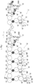
- Fig. 1 shows an apparatus 1 for manufacturing multi-segment articles, comprising an assembling apparatus 10, a first wrapping module 40, a cutting unit 50, a reorienting unit 60, an additional feeding unit 70 and a second wrapping module 80.
- the assembling apparatus 10 comprises at least two feeding modules 20 and an assembling unit 30, in the shown embodiment the assembling apparatus 10 comprises four feeding modules 20, 20', 20", 20′′′.
- the feeding module 20, 20', 20", 20'" is adapted to cut rods of at least one type and to feed segments of at least one type. Feeding modules which are adapted to cut rods of two types and to feed segments of two types are also known.
- the feeding module 20 comprises a hopper 21 for the rods MA, a receiving drum 22 provided with circumferentially arranged flutes in which the rods MA from the hopper 21 are situated, and drums for forming a stream of segments A formed by cutting the rods MA.
- the receiving drum 22 receives the rods MA from the hopper 21 and conveys the rods to the conveying drum 23.
- a cutting head 24 which is provided with one or more circular knives 24A for cutting the rods MA.
- the feeding module 20 comprises at least one shifting drum 25 and at least one aligning drum 26.
- the shifting drum 25 may also be referred to as a cascading drum wherein successive segments are arranged in successive flutes of this drum.
- the feeding module 20 supplies the segments A in the form of at least one stream.
- the rod MA, MB, MC, MD is cut into segments A, B, C, D respectively, the segments being fed in the form of streams to the assembling unit 30.
- the rods MA stored in the hopper 21 fill the flutes 28 arranged circumferentially on the receiving drum 22 during the rotation of this drum ( Fig. 3 ).
- the rods MA are held in the flutes 28 by means of vacuum supplied through holes in the bottom of the flute 28.
- the receiving drum 22 transfers the rods MA at the transfer point X to the flutes 29 of the conveying drum 23 where the rods MA are also held by means of vacuum.
- the rod MA is cut into individual segments A, with the segments A formed from one rod MA forming a segment group G ( Fig. 3a ).
- the consecutively fed groups G of the segments A are transferred to the shifting drum 25 and further to the aligning drum 26 to form a stream of individual segments A in which the segments A move so that their axes are situated perpendicular to the direction of movement.
- the feeding module 20 supplies the segments A in the form of at least one stream of the segments A.
- An example of a stream of the segments A formed by cutting the rods MA is shown in Fig. 3b , the drums are not shown, there are presented the rods MA and the segments A are situated successively on the receiving drum 22, the conveying drum 23, the shifting drum 25 and the aligning drum 26.
- the shifting drum 25 varies the arrangement of the segments A with respect to one another, the shifting drum 25 may also be referred to as the cascading drum.
- Fig. 3c shows the forming of two streams of the segments A produced by cutting of the rods MA.
- the stream of the segments A can be transferred further to an assembling unit 30 of the assembling module of the machine for manufacturing the multi-segment articles.
- the quality control of the rods MA can be carried out.
- a rejector for removing defective rods from the process. Due to the location of the cutting process on the conveying drum 23, the receiving drum 22 may momentarily vary the speed in order to correct the efficiency of feeding the rods MA from the receiving drum 22 to the conveying drum 23.
- the feeding module 20 is provided with a filling sensor 91 for checking the presence of the rod MA in the flute 28 of the receiving drum 22. Furthermore, the feeding module 20 comprises a quality control sensor 92 for checking the quality of the conveyed rods MA.
- the feeding module 20 comprises a rod rejector 93 for rejecting defective rods MA.
- the rejector 93 comprises a pressure vessel 94 and a valve 95 on a feed channel 96 through which compressed air is supplied.
- the rejection of the rod MA is achieved by momentarily supplying compressed air to a rejection channel 97.
- the rejection force acting on the rod MA is greater than the force holding the rod MA in the flute 28.
- the rejected defective rod is indicated as MA'.
- the receiving drum 22 is adapted to operate at a variable and adjustable rotational speed, preferably with position control, for example by coupling the receiving drum 22 to a digitally controlled servo drive which is provided with a position encoder.
- the rotational speed ⁇ 1 of the receiving drum 22 is synchronised with the rotational speed ⁇ 2 of the conveying drum 23, the synchronisation of the receiving drum 22 and the conveying drum 23 being maintained when all flutes 28 of the receiving drum 22 are filled.
- individual flutes 28 may be unfilled.
- the occurrence of an unfilled flute 28' may be due to a momentary ineffective receiving of the rod MA' from the hopper 21.
- An unfilled flute 28' will also occur when a defective rod MA' is detected by the quality control sensor 92 and the rejector 93 is activated. When a low-quality rod MA' is detected by the sensor 92, the rejector 93 rejects such a defective rod.
- the flute 28' is denoted as the flute from which the defective rod MA' was rejected after activation of the rejector 93.
- the flute 28' will denote both a flute from which a defective rod was rejected and a flute that was not filled by the rod MA from the hopper 21.
- the receiving drum 22 is adapted to transfer the rod MA at the transfer point X from the flute 28 of the receiving drum 22 to the flute 29 of the conveying drum 23, the receiving drum 22 rotating at a speed ⁇ 1 and the conveying drum 23 rotating at a speed ⁇ 2 adjusted to the speed ⁇ 1 so that the linear speeds of the receiving drum 22 and the conveying drum 23 are equal.
- the feeding module 20 is adapted to momentarily accelerate the receiving drum 22 before the unfilled flute 28' of the receiving drum 22 reaches the transfer point X.
- the receiving drum 22 is adapted to make a rotational movement with an increased speed ⁇ 1' so that when an unfilled flute 28' of the receiving drum 22 is detected, the receiving drum 22 moves with an increased speed ⁇ 1' so that at the transfer point X of the rod MA to the flute 29 of the conveying drum 23, there is another filled flute 28" of the receiving drum 22 and another empty flute 29' of the conveying drum 23.
- An effect of the acceleration of the receiving drum 22 is that all flutes 29 on the conveying drum 23 are filled, i.e. the "unfilling" of the flute 28' is not transferred to the conveying drum 23.
- Fig. 4 shows the successive phases of movement of the receiving drum 22 to be carried out in order to eliminate the "unfilling", the shown phases of movement include the acceleration of the receiving drum 22, the figure also shows the phases of movement of the conveying drum 23 related to the movement of the receiving drum 22.
- the rod MA is transferred to the flute 29 and the receiving drum 22 moves at a nominal rotational speed ⁇ 1 adjusted to the rotational speed ⁇ 2 of the conveying drum 23.
- the next flute to be filled is designated as 29', the flute 28' which approaches the transfer point X being unfilled.
- the receiving drum 22 Just after transferring the rod MA to the flute 29 of the conveying drum 23, the receiving drum 22 starts to move at an increased speed ⁇ 1', as shown in the phase b, where the flute 28' moves faster than the flute 29' to be filled with the next rod MA.
- the receiving drum 22 continues to rotate at the increased speed ⁇ 1' and the conveying drum 23 rotates at the nominal speed ⁇ 2.
- the filled flute 28' of the receiving drum 22 and the empty flute 29' of the conveying drum 23 are positioned opposite each other, i.e.
- the receiving drum 22 reduces its speed to the nominal rotational speed ⁇ 1 and the conveying drum 23 rotates at the nominal rotational speed ⁇ 2.
- the receiving drum 22 and the conveying drum 23 continue to rotate synchronously with the speeds ⁇ 1 and ⁇ 2, respectively, enabling the transfer of the successive rods MA.
- An assembling unit 30 comprises assembling drums 31 and conveying drums 32 which are provided with flutes into which the segments are received and conveyed.
- the assembling drum 31, 31', 31", 31′′′ is adapted to receive and to convey a stream of the segments A, B, C, D, respectively.
- the first assembling drum 31 is adapted to receive only the segments A, while the assembling drum 31' is adapted to receive a stream of the segments A from the feeding module 20 via the conveying drum 32 and to receive a stream of the segments B from the feeding module 20', the streams of the segments A and B being assembled on the assembling drum 31'.
- the streams of the segments A, B are received together, and the stream of the segments C is received from the feeding module 20".
- the streams of the segments A, B, C are received together, and the stream of the segments D is received from the feeding module 20'".
- the streams of the segments A, B, C, D are arranged in such a way that adjacent segments in the flutes are spaced apart.
- the assembling unit 30 is adapted to feed the group G1 comprising the segments A, B, C, D. Due to the adaptation of the assembling unit 30 to form a group of segments with spacing, the segments A, B, C, D can be fed in any order, the examples of forming processes being described below in this description.
- the first wrapping module 40 comprises a feeding unit 41 for feeding a first wrapping material MW1, a cutting unit 42 for cutting the strand of the first wrapping material MW1 into sections of the first wrapping material W1, and a rolling unit 43 for wrapping the group of segments.
- the first wrapping module 40 comprises a conveying drum 44 which is adapted to receive and to convey the group of segments, once the group of segments G1 has been assembled in the assembling unit, the segments of the group G1 are pushed together so as to form the group G2 in which the segments touch the ends of one another, the pushing being performed by mechanisms known in the state of the art before wrapping with the section of the first wrapping material.
- the rolling unit 43 is adapted to wrap a section of the first wrapping material W1 around the group G2.
- the rod thus formed is designated as R (stage g).
- the cutting unit 50 situated downstream of the first wrapping module 40 in the direction T of the process of manufacturing the multi-segment articles is provided with a circular knife 51 for cutting the multi-segment rod R into two halves, i.e. into two half multi-segment rods designated as R1 and R2 (stage h in Fig. 2 ).
- the cutting is effected so that the segment B of the multi-segment rod R is cut into two halves.
- the reorienting module 60 is adapted to vary the orientation of the half multi-segment rods R1 and R2 with respect to each other, i.e. to vary the mutual position of the rods R1 and R2 while they are conveyed.
- the reorienting module 60 may be provided with reorienting drums known in the tobacco industry which, in addition to circumferential conveying, reorient the conveyed rod-like articles axially and/or transversely to the axes of such articles.
- the reorienting module 60 may be provided with rotating drums known in the tobacco industry which, in addition to circumferential conveying, rotate the conveyed rod-like articles around axes which are substantially perpendicular to the circumferential surface.
- the reorienting module 60 is adapted to vary the positioning of the rod-like articles R1 and R2 relative to each other. As a result of the operation of the reorienting module 60, the rods R1 and R2 are reoriented so that the segments D being the ends of the rods R1 and R2, originally oriented away from each other, are oriented towards each other, while the half segments B, arranged opposite to the segments D in the rods R1 and R2, originally oriented towards each other, are oriented away from each other. In addition, the rods R1 and R2 become coaxially situated, and there will be a gap maintained between the rods R1 and R2.
- the additional feeding module 70 comprises a hopper 71, a receiving drum 72 provided with circumferentially arranged flutes in which the rods ME from the hopper 71 are placed (the structure of the additional feeding module 70 is the same as that of the first feeding module 20).
- the rods ME are conveyed to a conveying drum 73.
- a cutting head 74 which is provided with one or more circular knives for cutting the rods.
- the additional feeding module 70 comprises at least one shifting drum 75 and at least one aligning drum 76.
- the additional feeding module 70 is adapted to feed a stream of additional segments E. After feeding the additional segment E, there is formed a group S1 including a half multi-segment rod R1, a segment E and a half multi-segment rod R2 with gaps.
- the additional feeding module 70 is constructed similar to the feeding module 20 described above, namely it is provided with a filling sensor 91 for checking the presence of the rod MA in a flute of the receiving drum 72. Furthermore, the feeding module 70 comprises a quality control sensor 92 for checking the quality of the conveyed rods MA.
- the feeding module 70 comprises a rod rejector 93 for rejecting defective rods MA which comprises a pressure vessel 94 and a valve 95 on a feed channel 96 through which compressed air is supplied.
- the second wrapping module 80 comprises a feeding unit 81 for feeding a second wrapping material MW2, a cutting unit 82 for cutting the second wrapping material MW2 into sections of the second wrapping material W2, and a rolling unit 83.
- the second wrapping module 80 comprises a conveying drum 84 which is adapted to receive and to convey a group S1 which includes a half multi-segment rod R1, a segment E and a second half multi-segment rod R2.
- the group of elements R1, E, R2 which have been pushed together is designated as S2.
- the conveying drum 84 is adapted to convey the group S2 of the elements R1, E, R2 pushed together, along with a section of the second wrapping material W2.
- the rolling unit 83 is adapted to wrap the section of the second wrapping material W2 around the group S2 on the rolling drum 83A.
- the rod thus formed is designated as P.
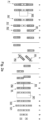
- the feeding module 20 cuts the rods MA into the segments A and feeds two segments A to the assembling unit 30 (stage a in Fig. 2a ), the feeding module 20' cuts the rods MB and feeds the segment B (stage b), the feeding module 20" cuts the rods MC and feeds two segments C (stage c), the feeding module 20′′′ cuts the rods MD and feeds two segments D (stage d).
- the segments A, B, C, D are conveyed in the assembling unit 30, whereas the assembling unit 30 supplies the segment group G1 comprising the segments A, B, C, D.
- the segments A, B, C, D are further conveyed and are pushed together, whereas the segments A, B, C D which have been pushed together form the segment group G2 (step e).
- the wrapping module 40 sections of the first wrapping material W1 are cut from the strand of the first wrapping material MW1 and are wrapped around the segment group G2 (stage f), after wrapping on the rolling drum 43A by means of the rolling unit 43B, the rod R is formed (stage g).
- the rod R is cut by the cutting unit 50 into two half multi-segment rods R1 and R2 (stage h), whereas the rods R1 and R2 are adjacent to each other with the half segments B and are positioned coaxially.
- the rods R1 and R2 are reoriented in the reorienting unit 60 (stages i, j, k, l, m, n) so that, after reorienting, they are again positioned coaxially, with a gap, with opposite ends than initially, namely the half segments B are oriented away from each other, while the segments D are oriented towards each other.
- the reorientation is carried out by rotating the rods R1 and R2 shown in the stage k, and the stages j and I represent the movement of the rods before and after rotation, whereas these stages may be omitted.
- the additional feeding module 70 cuts the rods ME into the segments E and feeds the segments E between the rods R1 and R2, after inserting the segment E a group S1 including the rod R1, the segment E and the rod R2 is formed (stage o), with gaps between the rods R1, the rods R2 and the segment E being maintained. After pushing the rods R1, R2 and the segment E together, a group S2 with no gaps among the rods R1, R2 and the segment E is formed (stage p).
- the second wrapping module 80 sections of the second wrapping material W2 are cut from the strand of the second wrapping material MW2 and are wrapped around the segment group S2 (stage r), after wrapping on the rolling drum 83A by means of the rolling unit 83, the rod P is formed (stage s).
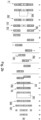
- the feeding module 20 cuts the rods MB into the segments B and feeds the segment B to the assembling unit 30 (stage a in Fig. 2b ), the feeding module 20' cuts the rods MA and feeds two segments A (stage b), the feeding module 20" cuts the rods MD and feeds two segments D (stage c), the feeding module 20'” cuts the rods MC and feeds two segments C (stage d).
- the process stages e to h are carried out as described for the first embodiment.
- the half multi-segment rods R1 and R2 are displaced transversely to the axis of the rods R1, R2, at the stages k, l, m the rods R1, R2 are reoriented so that after the axial displacement of the rods R1, R2 the half segments B are oriented away from each other, while the segments D are oriented towards each other.
- the rods R1 and R2 are displaced transversely to their axes so that the rods R1 and R2 are positioned coaxially. The further process is carried out as in the first embodiment.
- the feeding module is provided with a quality control sensor 92 for checking the quality of the conveyed rods MA, a replenishing apparatus 98 for feeding the rods MA and the rejector 93.
- the rejector 93 for removing defective rods comprises the pressure vessel 94, the valve 95 and the feed channel 96.
- a controller S receives a signal indicating a defective rod MA' and sends the signal to the rejector 93 so that the rejector 93 rejects such a defective rod MA', compressed air gets through the suplly channel 96 and the channel 97 to the rod MA' in the flute 28'.
- the replenishing apparatus 98 fills the empty flute 28' with a rod from an additional hopper 99, the replenishing apparatus 98 being provided with a rotational inserting element 100 adapted to feed the rods MA individually into the flute 28.
- the receiving drum 22 moves at a constant rotational speed ⁇ 1
- the conveying drum 23 moves at a speed ⁇ 2 adapted to the speed ⁇ 1.
- the feeding module is provided with the filling sensor 91 for checking the presence of the rod MA in the flute 28 of the receiving drum 22 and the filling apparatus 98 for feeding the rods MA.
- the controller S receives a signal indicating the absence of the rod and sends the signal to the filling apparatus 98 so that the empty flute 28' becomes filled with the rod MA.
- the filling apparatus 98 is provided with an inserting mechanism 101 which receives the rod MA from the additional hopper 99 and places it in the empty flute 28'.
- the receiving drum 22 moves at the constant speed ⁇ 1, while the conveying drum 23 moves at the speed ⁇ 2 adapted to the speed ⁇ 1.
Landscapes
- Cigarettes, Filters, And Manufacturing Of Filters (AREA)
Abstract
Description
- The object of this application is a feeding module for feeding segments in the form of rod-like articles, an apparatus and a method for manufacturing multi-segment articles.
- At present, the tobacco industry manufactures rod-like articles comprising a plurality of elements, namely tobacco elements containing tobacco or material containing processed tobacco, filter elements, elements containing aromatic substances, distance elements used for example to cool tobacco smoke. In this application, these various elements will be referred to as segments and articles containing such segments as multi-segment articles or multi-segment rods. In the process of manufacturing multi-segment filter rods or multi-segment smoking articles, the segments are usually manufactured by cutting the rods that are multiples of the segments. The patent
EP2230951B1 discloses an apparatus for assembling groups of segments which are used in the process of manufacturing multi-segment articles, the rods are received from a hopper and cut on a single multi-segment conveyor drum. In the state of the art, there are known many apparatuses on which the rods are cut into individual segments, such apparatuses are disclosed among others in the documentsGB2267021A EP1393640A1 ,EP1397965A1 ,EP1493340A1 . - The tobacco industry uses active quality control that includes the rejection of defective rods. The active rejection of defective rods is one of the processes that affect the filling of conveying flutes of conveying drums, a problem that is solved, for example, by filling up the rods or by adjusting the rotational speed of the conveying drum that transfers the rods further through the processing line. Processes involving an increase in speed adversely affect the process of cutting rod-like articles which, in order to maintain the quality of the products, requires the feed speed of the articles to be cut to be as constant as possible. Therefore, there is a need for apparatuses wherein both processes with a variable rotational speed and processes requiring a constant conveyor drum speed are possible. In the state-of-the-art documents presented, the conveying drums on which cutting takes place cannot be accelerated. There is a need for the rod receiving process to be independent of the rod cutting process.
- The object of the invention is a feeding module for feeding segments in the form of rod-like articles, comprising a hopper for storing rods, a receiving drum for receiving the rods from the hopper, a conveying drum, a cutting head, situated at the conveying drum, for cutting the rods into individual segments, a shifting drum for varying the mutual position of the segments, an aligning drum for forming at least one stream of the segments.
- The feeding module according to the invention is further characterised in that the feeding module comprises a filling sensor for checking the presence of the rod in a flute of the receiving drum.
- The feeding module according to the invention is further characterised in that the feeding module comprises a quality control sensor for the rod.
- The feeding module according to the invention is further characterised in that the feeding module comprises a rod rejector for rejecting the rod from the flute of the receiving drum.
- The feeding module according to the invention is characterised in that the receiving drum is adapted to make a rotational movement at an increased speed so that when an unfilled flute on the receiving drum is detected or a rod is rejected from a flute on the receiving drum, it moves at the increased speed so that at the point of transfer of the rod into the flute of the conveying drum, there is another filled flute of the receiving drum and another empty flute of the conveying drum.
- The feeding module according to the invention is further characterised in that the feeding module is provided with a replenishing apparatus for feeding the rod into the flute of the receiving drum.
- The feeding module according to the invention is further characterised in that the filling apparatus comprises an additional hopper for the rods.
- Furthermore, the object of the invention is an apparatus for manufacturing multi-segment articles comprising at least two feeding modules for feeding the segments formed after cutting the rods according to the invention, and an assembling unit provided with assembling drums and conveying drums, for receiving the segments from the feeding modules and forming a group of the segments, a first wrapping module for feeding a section of a first wrapping material and wrapping the group of the segments which have been pushed together so as to form a multi-segment rod, a cutting unit for cutting the formed rod into half multi-segment rods. The apparatus according to the invention further comprises an additional feeding module according to the invention for cutting an additional rod and feeding additional segments between the half multi-segment rods, and a second wrapping module for feeding a section of a second wrapping material and wrapping the two half multi-segment rods and the additional segment.
- The object of the invention is also a method of manufacturing multi-segment articles comprising steps wherein, in the feeding modules, the rods are fed from a hopper for storing the rods by means of a receiving drum for receiving the rods, the rods are cut into segments by means of a cutting head, situated at the conveying drum, for cutting the rods into individual segments, the segments are fed to an assembling unit, via the shifting drum for varying mutual position of the segments and an aligning drum for forming at least one stream of the segments, then segment groups are formed in the assembling unit provided with the assembling drums and the conveying drums for receiving the segments from the feeding modules, the segments are pushed together in the group so that the segments are in contact with one another. In a further step, a section of a first wrapping material is fed in a first wrapping module and a group of the segments which have been pushed together is wrapped whereby the multi-segment rod is formed, whereas by means of the conveying drum the groups of the segments are received and the groups of the segments which have been pushed together are conveyed along with the section of the first wrapping material, and then the groups of the segments which have been pushed together are wrapped with the section of the first wrapping material.
- In the next step, in the cutting unit, the formed multi-segment rod is cut into half multi-segment rods, in an additional feeding module for cutting the additional rod and feeding additional segments between the half multi-segment rods: the rods are received from the hopper, the rods are conveyed by means of the conveying drum, then the cutting head cuts the rods into individual segments, with the cutting head being situated at the conveying drum, then the mutual position of the segments is varied by means of the shifting drum and at least one stream of the segments is formed by means of an aligning drum. In the next step, a section of a second wrapping material is fed and the two half multi-segment rods and the additional segment are wrapped by means of a second wrapping module.
- The method according to the invention is further characterised by comprising a step wherein an empty flute on the drum is identified, and once the empty flute on the receiving drum is identified, the speed of the receiving drum is increased relative to the speed of the conveying drum so that at the point of transfer of the rod into the flute of the conveying drum, there is another filled flute of the receiving drum and another empty flute of the conveying drum.
- The method according to the invention is further characterised in that the step of identifying the empty flute is carried out by using a filling sensor for checking the presence of the rod in the flute.
- The method according to the invention is characterised in that the step of identifying the empty flute is carried out by means of a defective rod rejection signal from a sensor of rod quality control.
- The method according to the invention is characterised in that the empty flute is filled with a rod from the additional hopper by means of a rotational inserting element adapted to feed the rods individually into the flute.
- An advantage of the invention is that it allows the cutting process to be carried out at a constant speed of the conveying drum in an apparatus in which a variable speed of feeding the rod-like articles over the drums is used.
- The object of the invention is described in more detail on the basis of embodiments shown in a drawing in which:
- Fig. 1
- shows an apparatus for manufacturing multi-segment articles,
- Fig. 2a
- shows, in simplified terms, the process stages for manufacturing the multi-segment articles in the first embodiment,
- Fig. 2b
- shows, in simplified terms, the process stages for manufacturing the multi-segment articles in the second embodiment,
- Fig. 3
- shows a feeding module in the first embodiment,
- Fig. 3a
- shows a rod and a group of segments formed after cutting the rod,
- Fig. 3b
- shows the process of forming a segment stream,
- Fig. 3c
- shows the process of forming two segment streams,
- Fig. 4
- shows the phases of momentary acceleration of a receiving drum,
- Fig. 5
- shows the feeding module in the second embodiment, and
- Fig. 6
- shows the feeding module in the third embodiment.
-
Fig. 1 shows anapparatus 1 for manufacturing multi-segment articles, comprising an assemblingapparatus 10, afirst wrapping module 40, acutting unit 50, areorienting unit 60, anadditional feeding unit 70 and asecond wrapping module 80. - The assembling
apparatus 10 comprises at least twofeeding modules 20 and an assemblingunit 30, in the shown embodiment the assemblingapparatus 10 comprises fourfeeding modules feeding module - The
feeding module 20 comprises ahopper 21 for the rods MA, areceiving drum 22 provided with circumferentially arranged flutes in which the rods MA from thehopper 21 are situated, and drums for forming a stream of segments A formed by cutting the rods MA. Thereceiving drum 22 receives the rods MA from thehopper 21 and conveys the rods to the conveyingdrum 23. At the conveyingdrum 23, there is arranged acutting head 24 which is provided with one or morecircular knives 24A for cutting the rods MA. Thefeeding module 20 comprises at least one shiftingdrum 25 and at least one aligningdrum 26. The shiftingdrum 25 may also be referred to as a cascading drum wherein successive segments are arranged in successive flutes of this drum. Thefeeding module 20 supplies the segments A in the form of at least one stream. In the embodiment shown, in thefeeding modules unit 30. - The rods MA stored in the
hopper 21 fill theflutes 28 arranged circumferentially on the receivingdrum 22 during the rotation of this drum (Fig. 3 ). The rods MA are held in theflutes 28 by means of vacuum supplied through holes in the bottom of theflute 28. The receivingdrum 22 transfers the rods MA at the transfer point X to theflutes 29 of the conveyingdrum 23 where the rods MA are also held by means of vacuum. The rod MA is cut into individual segments A, with the segments A formed from one rod MA forming a segment group G (Fig. 3a ). The consecutively fed groups G of the segments A are transferred to the shiftingdrum 25 and further to the aligningdrum 26 to form a stream of individual segments A in which the segments A move so that their axes are situated perpendicular to the direction of movement. Thefeeding module 20 supplies the segments A in the form of at least one stream of the segments A. An example of a stream of the segments A formed by cutting the rods MA is shown inFig. 3b , the drums are not shown, there are presented the rods MA and the segments A are situated successively on the receivingdrum 22, the conveyingdrum 23, the shiftingdrum 25 and the aligningdrum 26. The shiftingdrum 25 varies the arrangement of the segments A with respect to one another, the shiftingdrum 25 may also be referred to as the cascading drum. On thedrum 26, the segments A are positioned so that they move along a single path of movement, in the view of the lateral surface of the drum along a single line.Fig. 3c shows the forming of two streams of the segments A produced by cutting of the rods MA. The stream of the segments A can be transferred further to an assemblingunit 30 of the assembling module of the machine for manufacturing the multi-segment articles. - On the receiving
drum 22, the quality control of the rods MA can be carried out. At the receivingdrum 22, there may be situated a rejector for removing defective rods from the process. Due to the location of the cutting process on the conveyingdrum 23, the receivingdrum 22 may momentarily vary the speed in order to correct the efficiency of feeding the rods MA from the receivingdrum 22 to the conveyingdrum 23. - In the first embodiment shown in
Fig. 3 , thefeeding module 20 is provided with a fillingsensor 91 for checking the presence of the rod MA in theflute 28 of the receivingdrum 22. Furthermore, thefeeding module 20 comprises aquality control sensor 92 for checking the quality of the conveyed rods MA. - The
feeding module 20 comprises arod rejector 93 for rejecting defective rods MA. Therejector 93 comprises apressure vessel 94 and avalve 95 on afeed channel 96 through which compressed air is supplied. The rejection of the rod MA is achieved by momentarily supplying compressed air to arejection channel 97. The rejection force acting on the rod MA is greater than the force holding the rod MA in theflute 28. InFig. 3 , the rejected defective rod is indicated as MA'. - The receiving
drum 22 is adapted to operate at a variable and adjustable rotational speed, preferably with position control, for example by coupling the receivingdrum 22 to a digitally controlled servo drive which is provided with a position encoder. The rotational speed ω1 of the receivingdrum 22 is synchronised with the rotational speed ω2 of the conveyingdrum 23, the synchronisation of the receivingdrum 22 and the conveyingdrum 23 being maintained when all flutes 28 of the receivingdrum 22 are filled. During the operation of thefeeding module 20,individual flutes 28 may be unfilled. The occurrence of an unfilled flute 28' may be due to a momentary ineffective receiving of the rod MA' from thehopper 21. An unfilled flute 28' will also occur when a defective rod MA' is detected by thequality control sensor 92 and therejector 93 is activated. When a low-quality rod MA' is detected by thesensor 92, therejector 93 rejects such a defective rod. InFig. 3a , the flute 28' is denoted as the flute from which the defective rod MA' was rejected after activation of therejector 93. Hereinafter, the flute 28' will denote both a flute from which a defective rod was rejected and a flute that was not filled by the rod MA from thehopper 21. - The receiving
drum 22 is adapted to transfer the rod MA at the transfer point X from theflute 28 of the receivingdrum 22 to theflute 29 of the conveyingdrum 23, the receivingdrum 22 rotating at a speed ω1 and the conveyingdrum 23 rotating at a speed ω2 adjusted to the speed ω1 so that the linear speeds of the receivingdrum 22 and the conveyingdrum 23 are equal. Thefeeding module 20 is adapted to momentarily accelerate the receivingdrum 22 before the unfilled flute 28' of the receivingdrum 22 reaches the transfer point X. Namely, the receivingdrum 22 is adapted to make a rotational movement with an increased speed ω1' so that when an unfilled flute 28' of the receivingdrum 22 is detected, the receivingdrum 22 moves with an increased speed ω1' so that at the transfer point X of the rod MA to theflute 29 of the conveyingdrum 23, there is another filledflute 28" of the receivingdrum 22 and another empty flute 29' of the conveyingdrum 23. An effect of the acceleration of the receivingdrum 22 is that all flutes 29 on the conveyingdrum 23 are filled, i.e. the "unfilling" of the flute 28' is not transferred to the conveyingdrum 23. -
Fig. 4 shows the successive phases of movement of the receivingdrum 22 to be carried out in order to eliminate the "unfilling", the shown phases of movement include the acceleration of the receivingdrum 22, the figure also shows the phases of movement of the conveyingdrum 23 related to the movement of the receivingdrum 22. In the phase a, the rod MA is transferred to theflute 29 and the receivingdrum 22 moves at a nominal rotational speed ω1 adjusted to the rotational speed ω2 of the conveyingdrum 23. On the conveying drum, the next flute to be filled is designated as 29', the flute 28' which approaches the transfer point X being unfilled. Just after transferring the rod MA to theflute 29 of the conveyingdrum 23, the receivingdrum 22 starts to move at an increased speed ω1', as shown in the phase b, where the flute 28' moves faster than the flute 29' to be filled with the next rod MA. In the phase c, the receivingdrum 22 continues to rotate at the increased speed ω1' and the conveyingdrum 23 rotates at the nominal speed ω2. In the phase d, the filled flute 28' of the receivingdrum 22 and the empty flute 29' of the conveyingdrum 23 are positioned opposite each other, i.e. their movements are synchronised so that the rod MA can be transferred between the flutes, whereas the receivingdrum 22 reduces its speed to the nominal rotational speed ω1 and the conveyingdrum 23 rotates at the nominal rotational speed ω2. The receivingdrum 22 and the conveyingdrum 23 continue to rotate synchronously with the speeds ω1 and ω2, respectively, enabling the transfer of the successive rods MA. - An assembling
unit 30 comprises assemblingdrums 31 and conveyingdrums 32 which are provided with flutes into which the segments are received and conveyed. The assemblingdrum drum 31 is adapted to receive only the segments A, while the assembling drum 31' is adapted to receive a stream of the segments A from thefeeding module 20 via the conveyingdrum 32 and to receive a stream of the segments B from the feeding module 20', the streams of the segments A and B being assembled on the assembling drum 31'. Similarly, on the assemblingdrum 31", the streams of the segments A, B are received together, and the stream of the segments C is received from thefeeding module 20". On the assemblingdrum 31‴, the streams of the segments A, B, C are received together, and the stream of the segments D is received from the feeding module 20'". In the assemblingunit 30, the streams of the segments A, B, C, D are arranged in such a way that adjacent segments in the flutes are spaced apart. The assemblingunit 30 is adapted to feed the group G1 comprising the segments A, B, C, D. Due to the adaptation of the assemblingunit 30 to form a group of segments with spacing, the segments A, B, C, D can be fed in any order, the examples of forming processes being described below in this description. - The
first wrapping module 40 comprises afeeding unit 41 for feeding a first wrapping material MW1, a cuttingunit 42 for cutting the strand of the first wrapping material MW1 into sections of the first wrapping material W1, and a rollingunit 43 for wrapping the group of segments. Thefirst wrapping module 40 comprises a conveyingdrum 44 which is adapted to receive and to convey the group of segments, once the group of segments G1 has been assembled in the assembling unit, the segments of the group G1 are pushed together so as to form the group G2 in which the segments touch the ends of one another, the pushing being performed by mechanisms known in the state of the art before wrapping with the section of the first wrapping material. The rollingunit 43 is adapted to wrap a section of the first wrapping material W1 around the group G2. The rod thus formed is designated as R (stage g). - The cutting
unit 50 situated downstream of thefirst wrapping module 40 in the direction T of the process of manufacturing the multi-segment articles is provided with acircular knife 51 for cutting the multi-segment rod R into two halves, i.e. into two half multi-segment rods designated as R1 and R2 (stage h inFig. 2 ). The cutting is effected so that the segment B of the multi-segment rod R is cut into two halves. - The reorienting
module 60 is adapted to vary the orientation of the half multi-segment rods R1 and R2 with respect to each other, i.e. to vary the mutual position of the rods R1 and R2 while they are conveyed. The reorientingmodule 60 may be provided with reorienting drums known in the tobacco industry which, in addition to circumferential conveying, reorient the conveyed rod-like articles axially and/or transversely to the axes of such articles. The reorientingmodule 60 may be provided with rotating drums known in the tobacco industry which, in addition to circumferential conveying, rotate the conveyed rod-like articles around axes which are substantially perpendicular to the circumferential surface. The reorientingmodule 60 is adapted to vary the positioning of the rod-like articles R1 and R2 relative to each other. As a result of the operation of the reorientingmodule 60, the rods R1 and R2 are reoriented so that the segments D being the ends of the rods R1 and R2, originally oriented away from each other, are oriented towards each other, while the half segments B, arranged opposite to the segments D in the rods R1 and R2, originally oriented towards each other, are oriented away from each other. In addition, the rods R1 and R2 become coaxially situated, and there will be a gap maintained between the rods R1 and R2. - The
additional feeding module 70 comprises ahopper 71, a receivingdrum 72 provided with circumferentially arranged flutes in which the rods ME from thehopper 71 are placed (the structure of theadditional feeding module 70 is the same as that of the first feeding module 20). The rods ME are conveyed to a conveyingdrum 73. At the conveyingdrum 73, there is situated a cuttinghead 74 which is provided with one or more circular knives for cutting the rods. Theadditional feeding module 70 comprises at least one shiftingdrum 75 and at least one aligningdrum 76. Theadditional feeding module 70 is adapted to feed a stream of additional segments E. After feeding the additional segment E, there is formed a group S1 including a half multi-segment rod R1, a segment E and a half multi-segment rod R2 with gaps. - The
additional feeding module 70 is constructed similar to thefeeding module 20 described above, namely it is provided with a fillingsensor 91 for checking the presence of the rod MA in a flute of the receivingdrum 72. Furthermore, thefeeding module 70 comprises aquality control sensor 92 for checking the quality of the conveyed rods MA. Thefeeding module 70 comprises arod rejector 93 for rejecting defective rods MA which comprises apressure vessel 94 and avalve 95 on afeed channel 96 through which compressed air is supplied. - The
second wrapping module 80 comprises afeeding unit 81 for feeding a second wrapping material MW2, a cuttingunit 82 for cutting the second wrapping material MW2 into sections of the second wrapping material W2, and a rollingunit 83. Thesecond wrapping module 80 comprises a conveyingdrum 84 which is adapted to receive and to convey a group S1 which includes a half multi-segment rod R1, a segment E and a second half multi-segment rod R2. The group of elements R1, E, R2 which have been pushed together is designated as S2. The conveyingdrum 84 is adapted to convey the group S2 of the elements R1, E, R2 pushed together, along with a section of the second wrapping material W2. The rollingunit 83 is adapted to wrap the section of the second wrapping material W2 around the group S2 on the rollingdrum 83A. The rod thus formed is designated as P. - In the process of manufacturing the multi-segment rod shown in simplified terms in
Fig. 2a , thefeeding module 20 cuts the rods MA into the segments A and feeds two segments A to the assembling unit 30 (stage a inFig. 2a ), the feeding module 20' cuts the rods MB and feeds the segment B (stage b), thefeeding module 20" cuts the rods MC and feeds two segments C (stage c), thefeeding module 20‴ cuts the rods MD and feeds two segments D (stage d). The segments A, B, C, D are conveyed in the assemblingunit 30, whereas the assemblingunit 30 supplies the segment group G1 comprising the segments A, B, C, D. The segments A, B, C, D are further conveyed and are pushed together, whereas the segments A, B, C D which have been pushed together form the segment group G2 (step e). In thewrapping module 40, sections of the first wrapping material W1 are cut from the strand of the first wrapping material MW1 and are wrapped around the segment group G2 (stage f), after wrapping on the rollingdrum 43A by means of the rolling unit 43B, the rod R is formed (stage g). The rod R is cut by the cuttingunit 50 into two half multi-segment rods R1 and R2 (stage h), whereas the rods R1 and R2 are adjacent to each other with the half segments B and are positioned coaxially. The rods R1 and R2 are reoriented in the reorienting unit 60 (stages i, j, k, l, m, n) so that, after reorienting, they are again positioned coaxially, with a gap, with opposite ends than initially, namely the half segments B are oriented away from each other, while the segments D are oriented towards each other. In the process of reorienting the rods R1 and R2 shown inFig. 2a , the reorientation is carried out by rotating the rods R1 and R2 shown in the stage k, and the stages j and I represent the movement of the rods before and after rotation, whereas these stages may be omitted. Theadditional feeding module 70 cuts the rods ME into the segments E and feeds the segments E between the rods R1 and R2, after inserting the segment E a group S1 including the rod R1, the segment E and the rod R2 is formed (stage o), with gaps between the rods R1, the rods R2 and the segment E being maintained. After pushing the rods R1, R2 and the segment E together, a group S2 with no gaps among the rods R1, R2 and the segment E is formed (stage p). In thesecond wrapping module 80, sections of the second wrapping material W2 are cut from the strand of the second wrapping material MW2 and are wrapped around the segment group S2 (stage r), after wrapping on the rollingdrum 83A by means of the rollingunit 83, the rod P is formed (stage s). - In the process of manufacturing the multi-segment rod in the second embodiment shown in simplified terms in
Fig. 2b , thefeeding module 20 cuts the rods MB into the segments B and feeds the segment B to the assembling unit 30 (stage a inFig. 2b ), the feeding module 20' cuts the rods MA and feeds two segments A (stage b), thefeeding module 20" cuts the rods MD and feeds two segments D (stage c), the feeding module 20'" cuts the rods MC and feeds two segments C (stage d). The process stages e to h are carried out as described for the first embodiment. At the stages i, j the half multi-segment rods R1 and R2 are displaced transversely to the axis of the rods R1, R2, at the stages k, l, m the rods R1, R2 are reoriented so that after the axial displacement of the rods R1, R2 the half segments B are oriented away from each other, while the segments D are oriented towards each other. At the stages m and n the rods R1 and R2 are displaced transversely to their axes so that the rods R1 and R2 are positioned coaxially. The further process is carried out as in the first embodiment. - In the second embodiment shown in
Fig. 5 , the feeding module is provided with aquality control sensor 92 for checking the quality of the conveyed rods MA, a replenishingapparatus 98 for feeding the rods MA and therejector 93. Therejector 93 for removing defective rods comprises thepressure vessel 94, thevalve 95 and thefeed channel 96. When a low-quality rod is detected by thesensor 92, a controller S receives a signal indicating a defective rod MA' and sends the signal to therejector 93 so that therejector 93 rejects such a defective rod MA', compressed air gets through thesuplly channel 96 and thechannel 97 to the rod MA' in the flute 28'. The replenishingapparatus 98 fills the empty flute 28' with a rod from anadditional hopper 99, the replenishingapparatus 98 being provided with a rotational insertingelement 100 adapted to feed the rods MA individually into theflute 28. During the operation of the feeding module, the receivingdrum 22 moves at a constant rotational speed ω1, while the conveyingdrum 23 moves at a speed ω2 adapted to the speed ω1. - In the third embodiment shown in
Fig. 6 , the feeding module is provided with the fillingsensor 91 for checking the presence of the rod MA in theflute 28 of the receivingdrum 22 and the fillingapparatus 98 for feeding the rods MA. When thesensor 91 detects the absence of the rod MA in the flute 28', the controller S receives a signal indicating the absence of the rod and sends the signal to the fillingapparatus 98 so that the empty flute 28' becomes filled with the rod MA. The fillingapparatus 98 is provided with an insertingmechanism 101 which receives the rod MA from theadditional hopper 99 and places it in the empty flute 28'. During the operation of the feeding module, the receivingdrum 22 moves at the constant speed ω1, while the conveyingdrum 23 moves at the speed ω2 adapted to the speed ω1.
Claims (13)
- A feeding module (20, 70) for feeding segments in the form of rod-like articles, comprisinga hopper (21, 71) for storing rods (MA),a receiving drum (22, 72) for receiving the rods (MA) from the hopper (21, 71),a conveying drum (23, 73),a cutting head (24, 74), situated at the conveying drum (23, 73), for cutting the rod (MA) into individual segments (A),a shifting drum (25, 75) for varying the mutual position of the segments (A),an aligning drum (26, 76) for forming at least one stream of the segments (A).
- The feeding module as in claim 1, characterised in that the feeding module (20, 70) comprises a filling sensor (91) for checking the presence of the rod (MA) in a flute (28) of the receiving drum (22, 72).
- The feeding module as in claim 1 or 2, characterised in that the feeding module (20, 70) comprises a quality control sensor (92) for the rod (MA).
- The feeding module as in claim 3, characterised in that the feeding module (20, 70) comprises a rod rejector (93) for rejecting the rod (MA') from the flute (28) of the receiving drum (22, 72).
- The feeding module as in any of the claims 2 to 4, characterised in that the receiving drum (22) is adapted to make a rotational movement at an increased speed (ω1') so that when an unfilled flute (28') on the receiving drum (22) is detected or a rod (MA') is rejected from the flute (28') on the receiving drum (22), it moves at the increased speed (ω1') so that at the point of transfer (X) of the rod (MA) into the flute (29) of the conveying drum (23), there is another filled flute (28") of the receiving drum (22) and another empty flute (29') of the conveying drum (23).
- The feeding module as in any of claims 2 to 4, characterised in that the feeding module (20, 70) is provided with a replenishing apparatus (98) for feeding the rod (MA) into the flute (28) of the receiving drum (22, 72).
- The feeding module as in any of the claims 1 to 4, characterised in that the replenishing apparatus (98) comprises an additional hopper (99) for the rods (MA).
- An apparatus (1) for manufacturing multi-segment articles comprisingat least two feeding modules (20) for feeding segments (A, B, C, D) formed after cutting rods (MA, MB, MC, MD) according to any of claims 1 to 7,an assembling unit (30) provided with assembling drums (31) and conveying drums (32), for receiving the segments (A, B, C, D) from the feeding modules (20) and forming a group (G1) of the segments,a first wrapping module (40) for feeding a section of a first wrapping material (W1) and wrapping a group (G2) of the segments (A, B, C, D) pushed together so as to form a multi-segment rod (R),a cutting unit (50) for cutting the formed rod (R) into half multi-segment rods (R1, R2),an additional feeding module (70) as in any of claims 1 to 7 for cutting an additional rod (ME) and feeding additional segments (E) between the half multi-segment rods (R1, R2),a second wrapping module (80) for feeding a section of a second wrapping material (W2) and wrapping two half multi-segment rods (R1, R2) and the additional segment (E).
- A method of manufacturing multi-segment articles comprising steps wherein,in feeding modules (20),rods (MA, MB, MC, MD) are fed from the hopper (21) for storing the rods (MA, MB, MC, MD), by means of the receiving drum (22) for receiving the rods (MA, MB, MC, MD),the rods (MA, MB, MC, MD) are cut into segments (A, B, C, D) by means of a cutting head (24), situated at the conveying drum (23), for cutting the rods (MA, MB, MC, MD) into individual segments (A, B, C, D),the segments (A, B, C, D) are fed to an assembling unit (30), via a shifting drum (25) for varying the mutual position of the segments (A, B, C, D) and an aligning drum (26) for forming at least one stream of the segments (A, B, C, D), thensegment groups (G1) are formed in the assembling unit (30) provided with assembling drums (31) and conveying drums (32) for receiving the segments (A, B, C, D) from the feeding modules (20),the segments (A, B, C, D) are pushed together in group (G1) so that the segments (A, B, C, D) are in contact with one another,in a first wrapping module (40), a section of a first wrapping material (W1) is fed and a group (G2) of the segments (A, B, C, D) pushed together is wrapped whereby the multi-segment rod (R) is formed, whereas by means of the conveying drum (44) the groups of the segments (A, B, C, D) are received and the groups (G2) of the segments (A, B, C, D) pushed together are conveyed along with a section of the first wrapping material (W1), and then the groups (G2) of the segments (A, B, C, D) pushed together are wrapped with the section of the first wrapping material (W1),in the cutting unit (50), the formed multi-segment rod (R) is cut into half multi-segment rods (R1, R2),in an additional feeding module (70) for cutting an additional rod (ME) and feeding additional segments (E) between the half multi-segment rods (R1, R2):the rods (ME) are received from the hopper (71),the rods (ME) are conveyed by means of a conveying drum (73), thenthe cutting head (74) cuts the rods into individual segments, the cutting head (74) being situated at the conveying drum (73),the mutual position of the segments (E) is varied by means of a shifting drum (75), thenat least one stream of the segments (E) is formed by means of an aligning drum (76), and thensections of a second wrapping material (W2) are fed and the two half multi-segment rods (R1, R2) and the additional segment (E) are wrapped with a section of the second wrapping material (W2) by means of a second wrapping unit (80).
- The method as in claim 9, further comprising the step wherein an empty flute (28') on the drum (22) is identified, and once the empty flute (28') on the receiving drum (22) has been identified, the speed (ω1) of the receiving drum (22) is increased relative to the speed (ω2) of the conveying drum (23) so that at the point of transfer (X) of the rod (MA) into the flute (29) of the conveying drum (23), there is another filled flute (28") of the receiving drum (22) and another empty flute (29') of the conveying drum (23).
- The method as in claim 10, characterised in that the step of identifying an empty flute (28') is carried out by means of a filling sensor (91) for checking the presence of the rod (MA) in the flute (28).
- The method as in claim 10 or 11, characterised in that the step of identifying the empty flute (28') is carried out by means of a defective rod (MA) rejection signal from a sensor (92) of quality control of the rod (MA).
- The method as in any of claims 9 to 12, characterised in that the empty flute (28') is filled with a rod from the additional hopper (99) by means of a rotational inserting element (100) adapted to feed the rods (MA) individually into the flute (28).
Priority Applications (2)
| Application Number | Priority Date | Filing Date | Title |
|---|---|---|---|
| EP22209345.2A EP4374714A1 (en) | 2022-11-24 | 2022-11-24 | Feeding module for feeding segments in the form of rod-like articles, apparatus and method for manufacturing multi-segment articles |
| PCT/IB2023/061779 WO2024110888A1 (en) | 2022-11-24 | 2023-11-22 | Feeding module for feeding segments in the form of rod-like articles, apparatus and method for manufacturing multi-segment articles |
Applications Claiming Priority (1)
| Application Number | Priority Date | Filing Date | Title |
|---|---|---|---|
| EP22209345.2A EP4374714A1 (en) | 2022-11-24 | 2022-11-24 | Feeding module for feeding segments in the form of rod-like articles, apparatus and method for manufacturing multi-segment articles |
Publications (1)
| Publication Number | Publication Date |
|---|---|
| EP4374714A1 true EP4374714A1 (en) | 2024-05-29 |
Family
ID=84981379
Family Applications (1)
| Application Number | Title | Priority Date | Filing Date |
|---|---|---|---|
| EP22209345.2A Pending EP4374714A1 (en) | 2022-11-24 | 2022-11-24 | Feeding module for feeding segments in the form of rod-like articles, apparatus and method for manufacturing multi-segment articles |
Country Status (2)
| Country | Link |
|---|---|
| EP (1) | EP4374714A1 (en) |
| WO (1) | WO2024110888A1 (en) |
Cited By (1)
| Publication number | Priority date | Publication date | Assignee | Title |
|---|---|---|---|---|
| EP4725332A1 (en) * | 2024-10-08 | 2026-04-15 | Körber Technologies GmbH | Apparatus and method for wrapping rod-like articles |
Citations (11)
| Publication number | Priority date | Publication date | Assignee | Title |
|---|---|---|---|---|
| US3768353A (en) * | 1970-07-06 | 1973-10-30 | Brown & Williamson Tobacco Corp | Cutting devices |
| US4044659A (en) * | 1974-10-15 | 1977-08-30 | Hauni-Werke Korber & Co. Kg | Apparatus for making composite filter plugs |
| GB2028099A (en) * | 1978-08-03 | 1980-03-05 | Molins Ltd | Filter attachment machines |
| GB2267021A (en) | 1992-05-19 | 1993-11-24 | Molins Plc | Filter cigarette machine |
| EP1393640A1 (en) | 2002-09-02 | 2004-03-03 | Hauni Maschinenbau AG | Method and Apparatus for composing groups of filtersegments |
| EP1397965A1 (en) | 2002-09-11 | 2004-03-17 | Hauni Maschinenbau AG | Injection of a medium in filter segments |
| EP1493340A1 (en) | 2003-07-01 | 2005-01-05 | Hauni Maschinenbau AG | Double line filter assembly machine |
| EP1913822A2 (en) * | 2006-10-16 | 2008-04-23 | Hauni Maschinbau AG | Stagger roller |
| EP2230951B1 (en) | 2007-12-10 | 2012-03-28 | Philip Morris Products S.A. | Method of compiling groups of segments in a process of producing multisegment filters and apparatus for preparing and compiling segments in groups in a process of producing multisegment filters |
| WO2019105813A1 (en) * | 2017-12-03 | 2019-06-06 | International Tobacco Machinery Poland Sp. Z O.O. | A replenishing device, an apparatus for manufacturing multisegment rods and a method for manufacturing multi-segment rods |
| EP3632224A1 (en) * | 2012-10-25 | 2020-04-08 | G.D Societa' Per Azioni | Assembly machine for producing cigarettes, and relative assembly method |
-
2022
- 2022-11-24 EP EP22209345.2A patent/EP4374714A1/en active Pending
-
2023
- 2023-11-22 WO PCT/IB2023/061779 patent/WO2024110888A1/en not_active Ceased
Patent Citations (11)
| Publication number | Priority date | Publication date | Assignee | Title |
|---|---|---|---|---|
| US3768353A (en) * | 1970-07-06 | 1973-10-30 | Brown & Williamson Tobacco Corp | Cutting devices |
| US4044659A (en) * | 1974-10-15 | 1977-08-30 | Hauni-Werke Korber & Co. Kg | Apparatus for making composite filter plugs |
| GB2028099A (en) * | 1978-08-03 | 1980-03-05 | Molins Ltd | Filter attachment machines |
| GB2267021A (en) | 1992-05-19 | 1993-11-24 | Molins Plc | Filter cigarette machine |
| EP1393640A1 (en) | 2002-09-02 | 2004-03-03 | Hauni Maschinenbau AG | Method and Apparatus for composing groups of filtersegments |
| EP1397965A1 (en) | 2002-09-11 | 2004-03-17 | Hauni Maschinenbau AG | Injection of a medium in filter segments |
| EP1493340A1 (en) | 2003-07-01 | 2005-01-05 | Hauni Maschinenbau AG | Double line filter assembly machine |
| EP1913822A2 (en) * | 2006-10-16 | 2008-04-23 | Hauni Maschinbau AG | Stagger roller |
| EP2230951B1 (en) | 2007-12-10 | 2012-03-28 | Philip Morris Products S.A. | Method of compiling groups of segments in a process of producing multisegment filters and apparatus for preparing and compiling segments in groups in a process of producing multisegment filters |
| EP3632224A1 (en) * | 2012-10-25 | 2020-04-08 | G.D Societa' Per Azioni | Assembly machine for producing cigarettes, and relative assembly method |
| WO2019105813A1 (en) * | 2017-12-03 | 2019-06-06 | International Tobacco Machinery Poland Sp. Z O.O. | A replenishing device, an apparatus for manufacturing multisegment rods and a method for manufacturing multi-segment rods |
Cited By (1)
| Publication number | Priority date | Publication date | Assignee | Title |
|---|---|---|---|---|
| EP4725332A1 (en) * | 2024-10-08 | 2026-04-15 | Körber Technologies GmbH | Apparatus and method for wrapping rod-like articles |
Also Published As
| Publication number | Publication date |
|---|---|
| WO2024110888A1 (en) | 2024-05-30 |
Similar Documents
| Publication | Publication Date | Title |
|---|---|---|
| NL2005190C2 (en) | A twin track machine and a method for manufacturing composite filters attachable to cigarettes, cigars and the like. | |
| EP3576553B1 (en) | Method and system for manufacture of multi-segment articles of tobacco industry | |
| EP0580150B1 (en) | Method of producing filter-tipped cigarettes | |
| US12035744B2 (en) | Replenishing device, an apparatus for manufacturing multi-segment rods and a method for manufacturing multi-segment rods | |
| JP6745806B2 (en) | Apparatus for producing multi-segment rods in tobacco industrial products and transport unit for transferring rod-like element rows | |
| US4943272A (en) | Apparatus for manufacturing cigarette filter | |
| EP3322309B1 (en) | Method and apparatus for shifting of rod-like articles, and apparatus of shifting of rod-like articles | |
| WO2024110888A1 (en) | Feeding module for feeding segments in the form of rod-like articles, apparatus and method for manufacturing multi-segment articles | |
| US20040200486A1 (en) | Method for combining smoking article components | |
| EP3639680B1 (en) | Production line and method for the production of rod-shaped articles of the tobacco industry | |
| EP3849348B1 (en) | A device for transferring rod-like articles used in the tobacco industry | |
| EP4378327A1 (en) | Apparatus for manufacturing multi-segment articles | |
| EP4374711B1 (en) | Feeding apparatus for feeding segments of tobacco industry material, feeding module for feeding segments of tobacco industry material and method of feeding tobacco industry rod-like articles | |
| EP4374713A1 (en) | Apparatus and method for manufacturing multi-segment articles | |
| EP4374715B1 (en) | Feeding module for feeding segments, apparatus for manufacturing multi-segment articles and method of feeding the segments for the manufacturing of multi-segment articles | |
| EP4161297B1 (en) | Method and machine for making multisegment articles | |
| EP3549458B1 (en) | Method and apparatus for conveying rod-like articles of tobacco industry | |
| EP4291047B1 (en) | Method of manufacturing rod-like articles for tobacco industry, apparatus for manufacturing rod-like articles and system for manufacturing rod-like articles | |
| US20230371579A1 (en) | Arrangement for transversely axially conveying of rod-shaped articles of the tobacco processing industry | |
| EP4480328B1 (en) | Pushing drum for the tobacco-processing industry and method for operating same | |
| US20260114499A1 (en) | Conveying and forming method and apparatus for forming a stream of tobacco industry segments | |
| KR20190074208A (en) | Apparatus for manufacturing of multi-element rods of tobacco industry |
Legal Events
| Date | Code | Title | Description |
|---|---|---|---|
| PUAI | Public reference made under article 153(3) epc to a published international application that has entered the european phase |
Free format text: ORIGINAL CODE: 0009012 |
|
| STAA | Information on the status of an ep patent application or granted ep patent |
Free format text: STATUS: THE APPLICATION HAS BEEN PUBLISHED |
|
| AK | Designated contracting states |
Kind code of ref document: A1 Designated state(s): AL AT BE BG CH CY CZ DE DK EE ES FI FR GB GR HR HU IE IS IT LI LT LU LV MC ME MK MT NL NO PL PT RO RS SE SI SK SM TR |
|
| STAA | Information on the status of an ep patent application or granted ep patent |
Free format text: STATUS: REQUEST FOR EXAMINATION WAS MADE |
|
| 17P | Request for examination filed |
Effective date: 20241129 |
|
| RBV | Designated contracting states (corrected) |
Designated state(s): AL AT BE BG CH CY CZ DE DK EE ES FI FR GB GR HR HU IE IS IT LI LT LU LV MC ME MK MT NL NO PL PT RO RS SE SI SK SM TR |
|
| GRAP | Despatch of communication of intention to grant a patent |
Free format text: ORIGINAL CODE: EPIDOSNIGR1 |
|
| STAA | Information on the status of an ep patent application or granted ep patent |
Free format text: STATUS: GRANT OF PATENT IS INTENDED |
|
| INTG | Intention to grant announced |
Effective date: 20251212 |