EP4373076A1 - Activation of vehicle convoy rear cameras - Google Patents
Activation of vehicle convoy rear cameras Download PDFInfo
- Publication number
- EP4373076A1 EP4373076A1 EP22207791.9A EP22207791A EP4373076A1 EP 4373076 A1 EP4373076 A1 EP 4373076A1 EP 22207791 A EP22207791 A EP 22207791A EP 4373076 A1 EP4373076 A1 EP 4373076A1
- Authority
- EP
- European Patent Office
- Prior art keywords
- vehicle
- camera
- rearmost
- processor device
- trailer
- Prior art date
- Legal status (The legal status is an assumption and is not a legal conclusion. Google has not performed a legal analysis and makes no representation as to the accuracy of the status listed.)
- Pending
Links
Images




Classifications
-
- H—ELECTRICITY
- H04—ELECTRIC COMMUNICATION TECHNIQUE
- H04N—PICTORIAL COMMUNICATION, e.g. TELEVISION
- H04N7/00—Television systems
- H04N7/18—Closed-circuit television [CCTV] systems, i.e. systems in which the video signal is not broadcast
- H04N7/181—Closed-circuit television [CCTV] systems, i.e. systems in which the video signal is not broadcast for receiving images from a plurality of remote sources
-
- B—PERFORMING OPERATIONS; TRANSPORTING
- B60—VEHICLES IN GENERAL
- B60R—VEHICLES, VEHICLE FITTINGS, OR VEHICLE PARTS, NOT OTHERWISE PROVIDED FOR
- B60R1/00—Optical viewing arrangements; Real-time viewing arrangements for drivers or passengers using optical image capturing systems, e.g. cameras or video systems specially adapted for use in or on vehicles
- B60R1/20—Real-time viewing arrangements for drivers or passengers using optical image capturing systems, e.g. cameras or video systems specially adapted for use in or on vehicles
- B60R1/22—Real-time viewing arrangements for drivers or passengers using optical image capturing systems, e.g. cameras or video systems specially adapted for use in or on vehicles for viewing an area outside the vehicle, e.g. the exterior of the vehicle
- B60R1/23—Real-time viewing arrangements for drivers or passengers using optical image capturing systems, e.g. cameras or video systems specially adapted for use in or on vehicles for viewing an area outside the vehicle, e.g. the exterior of the vehicle with a predetermined field of view
- B60R1/26—Real-time viewing arrangements for drivers or passengers using optical image capturing systems, e.g. cameras or video systems specially adapted for use in or on vehicles for viewing an area outside the vehicle, e.g. the exterior of the vehicle with a predetermined field of view to the rear of the vehicle
-
- H—ELECTRICITY
- H04—ELECTRIC COMMUNICATION TECHNIQUE
- H04N—PICTORIAL COMMUNICATION, e.g. TELEVISION
- H04N5/00—Details of television systems
- H04N5/222—Studio circuitry; Studio devices; Studio equipment
- H04N5/262—Studio circuits, e.g. for mixing, switching-over, change of character of image, other special effects ; Cameras specially adapted for the electronic generation of special effects
- H04N5/268—Signal distribution or switching
-
- B—PERFORMING OPERATIONS; TRANSPORTING
- B60—VEHICLES IN GENERAL
- B60D—VEHICLE CONNECTIONS
- B60D1/00—Traction couplings; Hitches; Draw-gear; Towing devices
- B60D1/58—Auxiliary devices
- B60D1/62—Auxiliary devices involving supply lines, electric circuits or the like
-
- B—PERFORMING OPERATIONS; TRANSPORTING
- B60—VEHICLES IN GENERAL
- B60R—VEHICLES, VEHICLE FITTINGS, OR VEHICLE PARTS, NOT OTHERWISE PROVIDED FOR
- B60R2300/00—Details of viewing arrangements using cameras and displays, specially adapted for use in a vehicle
- B60R2300/10—Details of viewing arrangements using cameras and displays, specially adapted for use in a vehicle characterised by the type of camera system used
- B60R2300/105—Details of viewing arrangements using cameras and displays, specially adapted for use in a vehicle characterised by the type of camera system used using multiple cameras
-
- B—PERFORMING OPERATIONS; TRANSPORTING
- B60—VEHICLES IN GENERAL
- B60R—VEHICLES, VEHICLE FITTINGS, OR VEHICLE PARTS, NOT OTHERWISE PROVIDED FOR
- B60R2300/00—Details of viewing arrangements using cameras and displays, specially adapted for use in a vehicle
- B60R2300/40—Details of viewing arrangements using cameras and displays, specially adapted for use in a vehicle characterised by the details of the power supply or the coupling to vehicle components
-
- G—PHYSICS
- G08—SIGNALLING
- G08G—TRAFFIC CONTROL SYSTEMS
- G08G1/00—Traffic control systems for road vehicles
- G08G1/16—Anti-collision systems
- G08G1/167—Driving aids for lane monitoring, lane changing, e.g. blind spot detection
Definitions
- the disclosure relates generally to a vehicle forming a convoy with at least two trailers.
- the disclosure relates to activation of vehicle convoy rear cameras.
- the disclosure can be applied in heavy-duty vehicles, such as trucks, buses, and construction equipment. Although the disclosure may be described with respect to a particular vehicle, the disclosure is not restricted to any particular vehicle.
- a rear camera of the truck is commonly used for providing a rear view to a driver via a display arranged in a truck cabin.
- a vehicle e.g. a truck
- a rear camera of the truck is commonly used for providing a rear view to a driver via a display arranged in a truck cabin.
- the truck forms a convoy with one or more trailers being attached to a rear of the truck, providing a correct convoy rear view is challenging.
- a computer system comprising a processor device configured to determine electronic communication with at least two trailers attached to a vehicle, the trailers and the vehicle each being equipped with a rear view camera, determine a rearmost camera of the rear view cameras and activate feed from the rearmost camera to a display of the vehicle.
- the first aspect of the disclosure may seek to resolve an issue of having a feed of a rearmost camera of a convoy being displayed on a display of a vehicle of the convoy.
- a technical benefit may include to provide a fully automated process of activating an appropriate rear camera upon forming a convoy.
- a computer-implemented method comprising determining, by a processor device of a computer system of a vehicle, electronic communication with at least two trailers attached to the vehicle, the trailers and the vehicle each being equipped with a rear view camera, determining, by the processor device, a rearmost camera of the rear view cameras and activating, by the processor device, feed from the rearmost camera to a display of the vehicle.
- the determining of a rearmost camera of the rear view cameras comprises determining, by the processor device, a predefined communication address at which each trailer is located in relation to the vehicle and determining, by the processor device, the rearmost camera of the rear view cameras based on the predefined communication addresses.
- a technical benefit may include the processor device concluding which camera, out of a plurality of cameras, is the rearmost camera.
- address number of each predefined communication address indicates trailer order in a convoy formed by the vehicle and the at least two trailers.
- a technical benefit may include the processor device concluding which camera, out of a plurality of cameras, is the rearmost camera from the address number.
- the processor device suppresses feed from the other rear view cameras to the display.
- a technical benefit may include the processor device only activating the feed of the rearmost camera of the convoy.
- the suppressing of feed from the rear view cameras of the other trailers to the display of the vehicle comprising requesting, by the processor device a computer system of the other trailers to omit transmission of the feed of the rear view cameras of the other trailers.
- a technical benefit may include the processor device communicating with computer system of the other trailers to suppress transmission of the feed of the rear view cameras not being the rearmost cameras of the convoy.
- the determining of electronic communication with at least two trailers attached to the vehicle comprises determining, by the processor device, electronic communication with at least two trailers attached to the vehicle by the at least two trailers connecting to a communication bus upon attachment to the vehicle, to which communication bus the processor device is connected,
- the communication bus is a Controller Area Network (CAN) bus, an Ethernet bus, or a Local Interconnect Network (LIN) bus.
- CAN Controller Area Network
- Ethernet Ethernet
- LIN Local Interconnect Network
- the wireless communication device of the vehicle is capable of communication via wifi, a mobile phone network, a vehicle-to-vehicle (V2V) communication network or Bluetooth.
- V2V vehicle-to-vehicle
- the processor device determines detachment of at least the rearmost trailer, determines a rearmost camera of the remaining rear view cameras and activates feed from the rearmost camera of the remaining rear view cameras to a display of the vehicle.
- a technical benefit may include the processor device determining a rearmost camera of the convoy upon detachment of one or more trailers from the convoy communicating with computer system of the other trailers to suppress transmission of the feed of the rear view cameras not being the rearmost cameras of the convoy.
- the activating of the feed from the rearmost camera to a display of the vehicle comprises requesting, by the processor device, a computer system of the rearmost trailer (18) to transmit the feed of the rearmost camera.
- the activating of the feed from the rearmost camera to a display of the vehicle comprises receiving, by the processor device, the feed of the rearmost camera via a computer system of the rearmost trailer upon the rearmost trailer attaching to the vehicle.
- a vehicle comprising the processor device configured to perform the method of the second aspect.
- a computer program product comprising program code for performing, when executed by the processor device, the method of the second aspect.
- a control system comprising one or more control units configured to perform the method according to the second aspect.
- a non-transitory computer-readable storage medium comprising instructions, which when executed by the processor device, cause the processor device to perform the method of the second aspect.
- FIG. 1 illustrates a vehicle in the form of truck 10 being equipped with a rear camera 15.
- a rear camera 15 is typically in communicative connection with a display 16 located in a cabin of the truck 10 to allow a driver of the truck 10 to attain a rear view of the truck 10 via the display 16 without having to turn his/her head towards a rear direction of the truck 10.
- the display 16 may be fixed in the cabin or portable, such has e.g. a tablet or smart phone.
- the rear camera 15 is typically activated to display a rear view when the truck 10 moves in a reverse direction, but may alternatively be activated at any time by the driver for attaining a rear view via the display.
- the truck 10 is equipped with a computer system 14 e.g. in the form of a so-called Electronic Control Unit (ECU) controlling operation of the truck 10.
- ECU Electronic Control Unit
- the ECU 14 generally comprises a processing unit 11 embodied in the form of one or more microprocessors arranged to execute a computer program 12 downloaded to a storage medium 13 associated with the microprocessor, such as a Random Access Memory (RAM), a Flash memory or a hard disk drive.
- the processing unit 11 is arranged to cause the ECU 14 to perform desired operations when the appropriate computer program 12 comprising computer-executable instructions is downloaded to the storage medium 13 and executed by the processing unit 11.
- the storage medium 13 may also be a computer program product comprising the computer program 12.
- the computer program 12 may be transferred to the storage medium 13 by means of a suitable computer program product, such as a Digital Versatile Disc (DVD) or a memory stick.
- DVD Digital Versatile Disc
- the processing unit 11 may alternatively be embodied in the form of a digital signal processor (DSP), an application specific integrated circuit (ASIC), a field-programmable gate array (FPGA), a complex programmable logic device (CPLD), etc.
- DSP digital signal processor
- ASIC application specific integrated circuit
- FPGA field-programmable gate array
- CPLD complex programmable logic device
- CPU central processing unit
- the communication between the rear camera 15 and the display 16 may e.g. occur via a Controller Area Network (CAN) bus, which is commonly used in vehicles for allowing device communication. In other examples, communication is performed via an Ethernet bus, a Local Interconnect Network (LIN) bus, etc.
- CAN Controller Area Network
- LIN Local Interconnect Network
- the communication is exemplified to be performed via a CAN bus 21 complying e.g. with the ISO 11992-2 standard.
- a combination of wired and wireless communication may be envisaged.
- a first trailer connecting to the truck 10 communicates with the truck 10 via the CAN bus while a second trailer connecting to the truck 10 utilizes wireless V2V communication.
- Communication between devices connected to the CAN bus 21 is typically supervised and controlled by the CPU 11 of the ECU 14 with which the truck 10 is arranged.
- vehicle 10 in FIG. 1 is depicted as a heavy-duty truck
- examples of the present disclosure may be implemented in other types of vehicles, such as in passenger cars, busses, light-weight trucks, mid-weight trucks, construction equipment, motorcycles, marine vessels, etc.
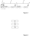
- FIG.3 illustrates an example where the truck 10 attaches to two interconnected trailers 17, 18 for forming a convoy, each trailer comprising a rear view camera 19, 20.
- a problem is then for the processing unit 11 of the truck 10 how to ascertain that a feed the rearmost camera 20 of the convoy is rendered on the display 16 of the truck 10.
- the feed of the rear view camera 15 of the truck 10 is displayed on the display 16.
- the first trailer 17 and the second trailer 18 may be consecutively or concurrently attached.
- the first trailer 17 and the second trailer 18 may be already interconnected when attached to the truck 10.
- FIG. 5 a system diagram of FIG. 5 illustrating connection of the ECU 14 of the truck 10 to the first trailer 17 and to the second trailer 18 and thus to the respective rear view camera 19, 20.
- the CPU 11 determines in 101 electronic communication with the trailers 17, 18 in that the trailers 17, 18 upon attachment to the truck 10 connect to the CAN bus 21 and thus to the CPU 11.
- each of the trailers 17, 18 comprises an ECU 22, 23 configured to manage communication of the respective trailer 17, 18 over the CAN bus 21.
- the CPU 11 determines in 102 a rearmost camera 20 of the three rear view cameras 15, 19, 20 and activates in 103 feed from the rearmost camera - being the rear camera 20 of the second trailer 18 - to the display 16 of the truck 10.
- the CPU 11 has thus supplied the feed of the rearmost camera 20 of the convoy, thereby enabling for the driver of the truck 10 to attain a rear view of the truck 10 via the display 16 without having to turn his/her head in rear direction of the truck 10.
- FIG. 6 shows a flowchart illustrating an example method wherein upon the trailers 17, 18 attaching to the truck 10 and thus the ECUs 22, 23 connecting to the CAN bus 21 and establishing communication with the CPU 11 of the ECU 14 of the truck 10 in 101, in accordance with the previously mentioned ISO 11992-2 standard, an address translation mechanism is exploited. This mechanism will further be described with reference to FIG. 7 .
- ach ECU 22, 23 may under ISO 11992-2 communicating over the CAN bus 21 with an immediately preceding vehicle (i.e. trailer or truck) utilize CAN bus address 192.
- the ECU 23 of the second trailer 18 may communicate with the ECU 22 of the first trailer 17 via address 192, and the ECU 22 of the first trailer 17 may in its turn communicate with the ECU 14 of the truck 10 using address 192 while performing translation of address 192 used by the ECU 23 of the second trailer 18 such that any data communicated by the second trailer 19 via the first trailer 18 is communicated to the ECU 14 of the truck 10 from the ECU 22 of the first trailer 17 using CAN bus address 184.
- a predefined bus address may be assigned for communication with each of the trailers 17, 18, where
- the CPU 11 of the ECU 14 may hence in 102a conclude that a trailer (and corresponding ECU) communicating via CAN bus address 192 is the first trailer 17 (and first ECU 22) while a trailer communicating over address 184 via the first trailer 17 is the second trailer 18 (and second ECU 23).
- a third trailer would according to the ISO 11992-2 standard correspondingly communicate with the truck 10 via the first and second trailers 17, 18 by using address 176, and so on.
- the CPU 11 communicates with the rear camera 15 of the truck 10 via address 200.
- the CPU 11 determines in 102b that the rear camera 20 of the second trailer 18 being located as bus address 184 must be the rearmost camera and activates the feed of the determined rearmost camera 20 to the display 16 of the truck 10 via the CAN bus 21 in 103.
- the CPU 11 of the ECU 14 with which the truck is equipped will be able to determine which of the rear cameras 15, 19, 20 is the rearmost camera of the convoy from the order of the CAN bus addresses via which the ECU 14 of the truck 10 and the ECUs 22, 23 of the first and second trailers 17, 18 communicate.
- the CPU 11 does not need information beforehand as regards the number of interconnected trailers to which the truck 10 attaches; any second trailer is located at bus address 184, while a third trailer is located at bus address 176, and so on, from the perspective of the truck 10.
- address number of each predefined communication address indicates trailer order in a convoy formed by the truck 10 and the trailers 17, 18.
- the CPU 11 activates the feed of the determined rearmost camera 20 to the display 16 of the truck 10 via the CAN bus 21 in 103 by actively requesting the feed from the rearmost camera 20 via address 184 of the CAN bus 21.
- the second trailer 18 actively provides the feed of the rearmost camera 20 upon attachment via address 192 to the first trailer 17 and further on to the truck 10 via address 184, while the preceding vehicle - i.e. the first trailer 17 - refrains from providing the feed of the rear camera 19 since a further rearmost trailer is present in the convoy.
- FIG. 8 shows a flowchart illustrating an example method wherein after the CPU 11 of the truck 10 determines communication with the trailers 17, 18 in 101, determines the rearmost camera 20 in 102 and activates the feed of the rearmost camera 20 to the truck display 16 in 103 as previously described, the CPU 11 further supresses any feed from the remaining rear cameras 15, 19 to the display 16.
- the rear camera 15 of the truck 10 is typically activated to provide the driver of the truck 10 with a rear view via the display 16.
- the CPU 11 will suppress feed from the other rear view cameras 15, 19 to the display 16 in 104.
- the suppressing of the feed from the other rear view cameras 15, 19 to the display 16 in 104 may be performed before, or simultaneously with, the activation of the feed from the rearmost camera 20 to the display 16 of the truck 10 in 103.
- the CPU 11 may perform a ping, thereby alerting all rear cameras 15, 19, 20 to provide a respective feed, in which case the CPU 11 may need to suppress the feed of the truck rear camera 15 and the rear camera 19 of the first trailer 17.
- the CPU 11 may actively request the second ECU 23 to transmit the feed of the rear view camera 20 of the second trailer 18.
- the feed may already be activated by the second ECU 23 upon the truck 10 attaching to the trailers 17, 18, in which case the feed is routed by the ECU 14 of the truck 10 to the display 16. This may further include supressing the feed of the rear camera 19 of the first trailer 17 and the feed of the truck rear camera 15, should these two feeds already be activated at attachment.
- FIG. 9 illustrates an example where the second trailer 18 is disconnected form the convoy.
- FIG. 10 showing a flowchart illustrating an example method.
- the CPU 11 determines a rearmost camera 19 of the remaining rear view cameras 15, 19 in the convoy. As described hereinabove, after the second trailer 18 has detached in 105, the CAN bus communication address 192 assigned to the first trailer 17 indicates that the first trailer 17 now is the rearmost trailer of the convey, since there is no longer a trailer in the convoy communicating via address 184, and the CPU 11 activates the feed from rear camera 19 of the first trailer 17 to the truck display 16.
- FIG. 3 illustrates a scenario where the truck 10 attaches to two interconnected trailers 17, 18 it may be that that the truck 10 initially attaches to the first trailer 17 and thereafter the convoy comprising the truck 10 and the first trailer 17 attaches to the second trailer, as shown in FIG. 11 .
- the CPU 11 determines in 101 electronic communication with the second trailer 18 in that the second trailer 18 upon attachment to the truck 10 connects to the CAN bus 21 and thus to the CPU 11.
- the CPU 11 determines in 102 a rearmost camera 20 of the three rear view cameras 15, 19, 20 and activates in 103 feed from the rearmost camera - being the rear camera 20 of the second trailer 18 - to the display 16 of the truck 10.
- the CPU 11 determines that the first trailer 17 located at communication address 192 no longer is the rearmost trailer of the convoy, since the second trailer 18 is assigned communication address 184.
- the CPU 11 will activate the feed of the rearmost camera 20 of the convoy, while suppressing the feed for the (no longer rearmost) rear camera 19 of the second trailer 17.
- While communication between the truck 10 and the trailers 17, 18 has been exemplified as being undertaken via wired CAN bus connections, it may also be envisaged that wireless communication between the truck 10 and the trailers 17, 18 is utilized (or a combination of wired and wireless communication). Ultimately, communication between any two devices in the convoy may be performed via wireless communication, such as the communication between three ECUs 14, 22, 23, given that the devices are capable of wireless communication.
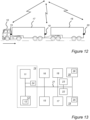
- FIG. 12 illustrates a scenario where the truck 10 attaches to two interconnected trailers 17, 18 as has been described in detail hereinabove.
- ECU 14 of the truck 10 communicates with the first ECU 22 and the second ECU 23 via the wired CAN communication bus 21 upon trailer attachment to the truck 10.
- the ECU 14 of the truck 10 is equipped with a wireless transmitter/receiver 24 (commonly referred to as a transceiver) for wireless communication with remotely located devices.
- a wireless transmitter/receiver 24 commonly referred to as a transceiver
- the rear view cameras 19, 20 are each equipped with wireless transceivers 25, 26.
- the respective ECU 22, 23 may provide the ECU 14 of the truck 10 with a communication address of each rear camera 19, 20, thereby allowing the ECU 14 of the truck 10 to activate the feed of the rearmost camera 20 to the display 16 via wireless communication between the transceivers 24, 26 (and potentially having the transceiver 24 to send a message to the transceiver 25 of the rear camera 19 of the first trailer 19 to perform camera feed suppression).
- FIG. 14 is a schematic diagram of a computer system 1400 for implementing examples disclosed herein.
- the computer system 1400 is adapted to execute instructions from a computer-readable medium to perform these and/or any of the functions or processing described herein.
- the computer system 1400 may be connected (e.g., networked) to other machines in a LAN, an intranet, an extranet, or the Internet. While only a single device is illustrated, the computer system 1400 may include any collection of devices that individually or jointly execute a set (or multiple sets) of instructions to perform any one or more of the methodologies discussed herein.
- any reference in the disclosure and/or claims to a computer system, computing system, computer device, computing device, control system, control unit, electronic control unit (ECU), processor device, etc. includes reference to one or more such devices to individually or jointly execute a set (or multiple sets) of instructions to perform any one or more of the methodologies discussed herein.
- control system may include a single control unit or a plurality of control units connected or otherwise communicatively coupled to each other, such that any performed function may be distributed between the control units as desired.
- such devices may communicate with each other or other devices by various system architectures, such as directly or via a Controller Area Network (CAN) bus, etc.
- CAN Controller Area Network
- the computer system 1400 may comprise at least one computing device or electronic device capable of including firmware, hardware, and/or executing software instructions to implement the functionality described herein.
- the computer system 1400 may include a processor device 1402 (may also be referred to as a control unit), a memory 1404, and a system bus 1406.
- the computer system 1400 may include at least one computing device having the processor device 1402.
- the system bus 1406 provides an interface for system components including, but not limited to, the memory 1404 and the processor device 1402.
- the processor device 1402 may include any number of hardware components for conducting data or signal processing or for executing computer code stored in memory 1404.
- the processor device 1402 may, for example, include a general-purpose processor, an application specific processor, a Digital Signal Processor (DSP), an Application Specific Integrated Circuit (ASIC), a Field Programmable Gate Array (FPGA), a circuit containing processing components, a group of distributed processing components, a group of distributed computers configured for processing, or other programmable logic device, discrete gate or transistor logic, discrete hardware components, or any combination thereof designed to perform the functions described herein.
- the processor device may further include computer executable code that controls operation of the programmable device.
- the system bus 1406 may be any of several types of bus structures that may further interconnect to a memory bus (with or without a memory controller), a peripheral bus, and/or a local bus using any of a variety of bus architectures.
- the memory 1404 may be one or more devices for storing data and/or computer code for completing or facilitating methods described herein.
- the memory 1404 may include database components, object code components, script components, or other types of information structure for supporting the various activities herein. Any distributed or local memory device may be utilized with the systems and methods of this description.
- the memory 1404 may be communicably connected to the processor device 1402 (e.g., via a circuit or any other wired, wireless, or network connection) and may include computer code for executing one or more processes described herein.
- the memory 1404 may include non-volatile memory 1408 (e.g., read-only memory (ROM), erasable programmable read-only memory (EPROM), electrically erasable programmable read-only memory (EEPROM), etc.), and volatile memory 1410 (e.g., random-access memory (RAM)), or any other medium which can be used to carry or store desired program code in the form of machine-executable instructions or data structures and which can be accessed by a computer or other machine with a processor device 1402.
- a basic input/output system (BIOS) 1412 may be stored in the non-volatile memory 1408 and can include the basic routines that help to transfer information between elements within the computer system 1400.
- BIOS basic input/output system
- the computer system 1400 may further include or be coupled to a non-transitory computer-readable storage medium such as the storage device 1414, which may comprise, for example, an internal or external hard disk drive (HDD) (e.g., enhanced integrated drive electronics (EIDE) or serial advanced technology attachment (SATA)), HDD (e.g., EIDE or SATA) for storage, flash memory, or the like.
- HDD enhanced integrated drive electronics
- SATA serial advanced technology attachment
- the storage device 1414 and other drives associated with computer-readable media and computer-usable media may provide non-volatile storage of data, data structures, computer-executable instructions, and the like.
- a number of modules can be implemented as software and/or hard-coded in circuitry to implement the functionality described herein in whole or in part.
- the modules may be stored in the storage device 1414 and/or in the volatile memory 1410, which may include an operating system 1416 and/or one or more program modules 1418. All or a portion of the examples disclosed herein may be implemented as a computer program product 1420 stored on a transitory or non-transitory computer-usable or computer-readable storage medium (e.g., single medium or multiple media), such as the storage device 1414, which includes complex programming instructions (e.g., complex computer-readable program code) to cause the processor device 1402 to carry out actions described herein.
- the computer-readable program code can comprise software instructions for implementing the functionality of the examples described herein when executed by the processor device 1402.
- the processor device 1402 may serve as a controller or control system for the computer system 1400 that is to implement the functionality described herein.
- the computer system 1400 also may include an input device interface 1422 (e.g., input device interface and/or output device interface).
- the input device interface 1422 may be configured to receive input and selections to be communicated to the computer system 1400 when executing instructions, such as from a keyboard, mouse, touch-sensitive surface, etc.
- Such input devices may be connected to the processor device 1402 through the input device interface 1422 coupled to the system bus 1406 but can be connected through other interfaces such as a parallel port, an Institute of Electrical and Electronic Engineers (IEEE) 1494 serial port, a Universal Serial Bus (USB) port, an IR interface, and the like.
- IEEE Institute of Electrical and Electronic Engineers
- USB Universal Serial Bus
- the computer system 1400 may include an output device interface 1424 configured to forward output, such as to a display, a video display unit (e.g., a liquid crystal display (LCD) or a cathode ray tube (CRT)).
- the computer system 1400 may also include a communications interface 1426 suitable for communicating with a network as appropriate or desired.
- an output device interface 1424 configured to forward output, such as to a display, a video display unit (e.g., a liquid crystal display (LCD) or a cathode ray tube (CRT)).
- the computer system 1400 may also include a communications interface 1426 suitable for communicating with a network as appropriate or desired.
- Relative terms such as “below” or “above” or “upper” or “lower” or “horizontal” or “vertical” may be used herein to describe a relationship of one element to another element as illustrated in the Figures. It will be understood that these terms and those discussed above are intended to encompass different orientations of the device in addition to the orientation depicted in the Figures. It will be understood that when an element is referred to as being “connected” or “coupled” to another element, it can be directly connected or coupled to the other element, or intervening elements may be present. In contrast, when an element is referred to as being “directly connected” or “directly coupled” to another element, there are no intervening elements present.
Landscapes
- Engineering & Computer Science (AREA)
- Multimedia (AREA)
- Signal Processing (AREA)
- Mechanical Engineering (AREA)
- Traffic Control Systems (AREA)
Abstract
Description
- The disclosure relates generally to a vehicle forming a convoy with at least two trailers. In particular aspects, the disclosure relates to activation of vehicle convoy rear cameras. The disclosure can be applied in heavy-duty vehicles, such as trucks, buses, and construction equipment. Although the disclosure may be described with respect to a particular vehicle, the disclosure is not restricted to any particular vehicle.
- Upon a vehicle (e.g. a truck) moving in a reverse direction, a rear camera of the truck is commonly used for providing a rear view to a driver via a display arranged in a truck cabin. However, when the truck forms a convoy with one or more trailers being attached to a rear of the truck, providing a correct convoy rear view is challenging.
- According to a first aspect of the disclosure, a computer system is provided comprising a processor device configured to determine electronic communication with at least two trailers attached to a vehicle, the trailers and the vehicle each being equipped with a rear view camera, determine a rearmost camera of the rear view cameras and activate feed from the rearmost camera to a display of the vehicle.
- The first aspect of the disclosure may seek to resolve an issue of having a feed of a rearmost camera of a convoy being displayed on a display of a vehicle of the convoy. A technical benefit may include to provide a fully automated process of activating an appropriate rear camera upon forming a convoy.
- According to a second aspect of the disclosure, a computer-implemented method is provided comprising determining, by a processor device of a computer system of a vehicle, electronic communication with at least two trailers attached to the vehicle, the trailers and the vehicle each being equipped with a rear view camera, determining, by the processor device, a rearmost camera of the rear view cameras and activating, by the processor device, feed from the rearmost camera to a display of the vehicle.
- In some examples, the determining of a rearmost camera of the rear view cameras comprises determining, by the processor device, a predefined communication address at which each trailer is located in relation to the vehicle and determining, by the processor device, the rearmost camera of the rear view cameras based on the predefined communication addresses. A technical benefit may include the processor device concluding which camera, out of a plurality of cameras, is the rearmost camera.
- In some examples, address number of each predefined communication address indicates trailer order in a convoy formed by the vehicle and the at least two trailers. A technical benefit may include the processor device concluding which camera, out of a plurality of cameras, is the rearmost camera from the address number.
- In some examples, the processor device suppresses feed from the other rear view cameras to the display. A technical benefit may include the processor device only activating the feed of the rearmost camera of the convoy.
- In some examples, the suppressing of feed from the rear view cameras of the other trailers to the display of the vehicle comprising requesting, by the processor device a computer system of the other trailers to omit transmission of the feed of the rear view cameras of the other trailers. A technical benefit may include the processor device communicating with computer system of the other trailers to suppress transmission of the feed of the rear view cameras not being the rearmost cameras of the convoy.
- In some examples, the determining of electronic communication with at least two trailers attached to the vehicle comprises determining, by the processor device, electronic communication with at least two trailers attached to the vehicle by the at least two trailers connecting to a communication bus upon attachment to the vehicle, to which communication bus the processor device is connected,
- In some examples, the communication bus is a Controller Area Network (CAN) bus, an Ethernet bus, or a Local Interconnect Network (LIN) bus.
- In some examples, the electronic communication between the vehicle and the at least two trailers is established via a wireless communication device of the vehicle. A technical benefit may include the processor device communicating wirelessly with devices to which the processer device has no wired connection.
- In some examples, the wireless communication device of the vehicle is capable of communication via wifi, a mobile phone network, a vehicle-to-vehicle (V2V) communication network or Bluetooth.
- In some examples, the processor device determines detachment of at least the rearmost trailer, determines a rearmost camera of the remaining rear view cameras and activates feed from the rearmost camera of the remaining rear view cameras to a display of the vehicle. A technical benefit may include the processor device determining a rearmost camera of the convoy upon detachment of one or more trailers from the convoy communicating with computer system of the other trailers to suppress transmission of the feed of the rear view cameras not being the rearmost cameras of the convoy.
- In some examples, the activating of the feed from the rearmost camera to a display of the vehicle comprises requesting, by the processor device, a computer system of the rearmost trailer (18) to transmit the feed of the rearmost camera.
- In some examples, the activating of the feed from the rearmost camera to a display of the vehicle comprises receiving, by the processor device, the feed of the rearmost camera via a computer system of the rearmost trailer upon the rearmost trailer attaching to the vehicle.
- In some examples, a vehicle is provided comprising the processor device configured to perform the method of the second aspect.
- In some examples, a computer program product is provided comprising program code for performing, when executed by the processor device, the method of the second aspect.
- In some examples, a control system is provided comprising one or more control units configured to perform the method according to the second aspect.
- In some examples, a non-transitory computer-readable storage medium is provided comprising instructions, which when executed by the processor device, cause the processor device to perform the method of the second aspect.
- The above aspects, accompanying claims, and/or examples disclosed herein above and later below may be suitably combined with each other as would be apparent to anyone of ordinary skill in the art.
- Additional features and advantages are disclosed in the following description, claims, and drawings, and in part will be readily apparent therefrom to those skilled in the art or recognized by practicing the disclosure as described herein. There are also disclosed herein control units, computer readable media, and computer program products associated with the above discussed technical benefits.
- With reference to the appended drawings, below follows a more detailed description of aspects of the disclosure cited as examples.
-
FIG. 1 illustrates a vehicle in the form of truck being equipped with a rear camera. -
FIG. 2 illustrates a system diagram according to an example of the present disclosure. -
FIG. 3 illustrates the truck forming a convoy with a first and a second trailer. -
FIG. 4 shows a flowchart of a method of the truck forming a convoy with the first trailer and the second trailer in an example. -
FIG. 5 illustrates a system diagram according to another example of the present disclosure. -
FIG. 6 shows a flowchart of a method of the truck forming a convoy with the first trailer and the second trailer in another example. -
FIG. 7 illustrates a CAN bus address translation mechanism. -
FIG. 8 shows a flowchart of a method of the truck forming a convoy with the first trailer and the second trailer in yet another example. -
FIG. 9 illustrates the second trailer being detached from the convoy. -
FIG. 10 shows a flowchart of a method of the second trailer being detached from the convoy in an example. -
FIG. 11 illustrates the truck and the first trailer attaching to the second trailer. -
FIG. 12 illustrates the truck performing wireless communication with the first and a second trailer. -
FIG. 13 illustrates a system diagram according to another example of the present disclosure. -
FIG. 14 shows a schematic diagram of a computer system for implementing examples disclosed herein. - Aspects set forth below represent the necessary information to enable those skilled in the art to practice the disclosure.
-
FIG. 1 illustrates a vehicle in the form oftruck 10 being equipped with arear camera 15. As shown inFIG. 2 , suchrear camera 15 is typically in communicative connection with adisplay 16 located in a cabin of thetruck 10 to allow a driver of thetruck 10 to attain a rear view of thetruck 10 via thedisplay 16 without having to turn his/her head towards a rear direction of thetruck 10. As is understood, thedisplay 16 may be fixed in the cabin or portable, such has e.g. a tablet or smart phone. - The
rear camera 15 is typically activated to display a rear view when thetruck 10 moves in a reverse direction, but may alternatively be activated at any time by the driver for attaining a rear view via the display. - Further, the
truck 10 is equipped with acomputer system 14 e.g. in the form of a so-called Electronic Control Unit (ECU) controlling operation of thetruck 10. - The
ECU 14 generally comprises aprocessing unit 11 embodied in the form of one or more microprocessors arranged to execute acomputer program 12 downloaded to astorage medium 13 associated with the microprocessor, such as a Random Access Memory (RAM), a Flash memory or a hard disk drive. Theprocessing unit 11 is arranged to cause theECU 14 to perform desired operations when theappropriate computer program 12 comprising computer-executable instructions is downloaded to thestorage medium 13 and executed by theprocessing unit 11. Thestorage medium 13 may also be a computer program product comprising thecomputer program 12. Alternatively, thecomputer program 12 may be transferred to thestorage medium 13 by means of a suitable computer program product, such as a Digital Versatile Disc (DVD) or a memory stick. As a further alternative, thecomputer program 12 may be downloaded to thestorage medium 13 over a network. Theprocessing unit 11 may alternatively be embodied in the form of a digital signal processor (DSP), an application specific integrated circuit (ASIC), a field-programmable gate array (FPGA), a complex programmable logic device (CPLD), etc. Theprocessing device 11 will in the following be referred to as a central processing unit (CPU).The communication between therear camera 15 and thedisplay 16 may e.g. occur via a Controller Area Network (CAN) bus, which is commonly used in vehicles for allowing device communication. In other examples, communication is performed via an Ethernet bus, a Local Interconnect Network (LIN) bus, etc. or a wireless network, such as a local wifi network, a mobile phone network, a vehicle-to-vehicle (V2V) communication network or even Bluetooth. In the following, the communication is exemplified to be performed via aCAN bus 21 complying e.g. with the ISO 11992-2 standard. - Further, a combination of wired and wireless communication may be envisaged. For instance, a first trailer connecting to the
truck 10 communicates with thetruck 10 via the CAN bus while a second trailer connecting to thetruck 10 utilizes wireless V2V communication. - Communication between devices connected to the
CAN bus 21 is typically supervised and controlled by theCPU 11 of theECU 14 with which thetruck 10 is arranged. - Although the
vehicle 10 inFIG. 1 is depicted as a heavy-duty truck, examples of the present disclosure may be implemented in other types of vehicles, such as in passenger cars, busses, light-weight trucks, mid-weight trucks, construction equipment, motorcycles, marine vessels, etc. -
FIG.3 illustrates an example where thetruck 10 attaches to twointerconnected trailers rear view camera processing unit 11 of thetruck 10 how to ascertain that a feed therearmost camera 20 of the convoy is rendered on thedisplay 16 of thetruck 10. Typically, while attaching to interconnectedfirst trailer 17 andsecond trailer 18 to form a convoy, the feed of therear view camera 15 of thetruck 10 is displayed on thedisplay 16. Thefirst trailer 17 and thesecond trailer 18 may be consecutively or concurrently attached. For example, thefirst trailer 17 and thesecond trailer 18 may be already interconnected when attached to thetruck 10. - This is resolved in an example of the present disclosure by the
CPU 11 of theECU 14 of thetruck 14 by an example method described with reference to a flowchart ofFIG. 4 . Reference will further be made to a system diagram ofFIG. 5 illustrating connection of theECU 14 of thetruck 10 to thefirst trailer 17 and to thesecond trailer 18 and thus to the respectiverear view camera - Hence, upon attaching to the
trailers CPU 11 determines in 101 electronic communication with thetrailers trailers truck 10 connect to theCAN bus 21 and thus to theCPU 11. - As is understood, similar to the
truck 10, each of thetrailers ECU respective trailer CAN bus 21. - Thereafter, the
CPU 11 determines in 102 arearmost camera 20 of the threerear view cameras rear camera 20 of the second trailer 18 - to thedisplay 16 of thetruck 10. - The
CPU 11 has thus supplied the feed of therearmost camera 20 of the convoy, thereby enabling for the driver of thetruck 10 to attain a rear view of thetruck 10 via thedisplay 16 without having to turn his/her head in rear direction of thetruck 10. - Further, to the driver of the
truck 10, the process of activating/deactivating the appropriate rear cameras upon forming a convoy with thetrailers -
FIG. 6 shows a flowchart illustrating an example method wherein upon thetrailers truck 10 and thus theECUs CAN bus 21 and establishing communication with theCPU 11 of theECU 14 of thetruck 10 in 101, in accordance with the previously mentioned ISO 11992-2 standard, an address translation mechanism is exploited. This mechanism will further be described with reference toFIG. 7 . - Now, upon attachment of the
trailers 17. 18 to thetruck 10,ach ECU CAN bus 21 with an immediately preceding vehicle (i.e. trailer or truck) utilizeCAN bus address 192. - Thus, the
ECU 23 of thesecond trailer 18 may communicate with theECU 22 of thefirst trailer 17 viaaddress 192, and theECU 22 of thefirst trailer 17 may in its turn communicate with theECU 14 of thetruck 10 usingaddress 192 while performing translation ofaddress 192 used by theECU 23 of thesecond trailer 18 such that any data communicated by thesecond trailer 19 via thefirst trailer 18 is communicated to theECU 14 of thetruck 10 from theECU 22 of thefirst trailer 17 usingCAN bus address 184. - As is understood, should a further trailer be attached to the convoy, that further trailer would communicate with the
second trailer 18 usingaddress 192 and - after two address translations being performed via the first andsecond trailers 17, 18 - ultimately communicate with the truck via CAN bus address 176. - As a result, from the perspective of the
ECU 14 of thetruck 10, a predefined bus address may be assigned for communication with each of thetrailers - communication with the
first trailer 17 is performed via CANbus communication address 192; - communication with the
second trailer 18 is performed viaaddress 184; and - communication with a potential third trailer is performed via address 176, and so on.
- The
CPU 11 of theECU 14 may hence in 102a conclude that a trailer (and corresponding ECU) communicating viaCAN bus address 192 is the first trailer 17 (and first ECU 22) while a trailer communicating overaddress 184 via thefirst trailer 17 is the second trailer 18 (and second ECU 23). - A third trailer would according to the ISO 11992-2 standard correspondingly communicate with the
truck 10 via the first andsecond trailers CPU 11 communicates with therear camera 15 of thetruck 10 via address 200. - In this particular example, the
CPU 11 determines in 102b that therear camera 20 of thesecond trailer 18 being located asbus address 184 must be the rearmost camera and activates the feed of the determinedrearmost camera 20 to thedisplay 16 of thetruck 10 via theCAN bus 21 in 103. - With this example method of the present disclosure, the
CPU 11 of theECU 14 with which the truck is equipped will be able to determine which of therear cameras ECU 14 of thetruck 10 and theECUs second trailers CPU 11 does not need information beforehand as regards the number of interconnected trailers to which thetruck 10 attaches; any second trailer is located atbus address 184, while a third trailer is located at bus address 176, and so on, from the perspective of thetruck 10. Hence, address number of each predefined communication address indicates trailer order in a convoy formed by thetruck 10 and thetrailers - In an example, the
CPU 11 activates the feed of the determinedrearmost camera 20 to thedisplay 16 of thetruck 10 via theCAN bus 21 in 103 by actively requesting the feed from therearmost camera 20 viaaddress 184 of theCAN bus 21. - In another example, the
second trailer 18 actively provides the feed of therearmost camera 20 upon attachment viaaddress 192 to thefirst trailer 17 and further on to thetruck 10 viaaddress 184, while the preceding vehicle - i.e. the first trailer 17 - refrains from providing the feed of therear camera 19 since a further rearmost trailer is present in the convoy. -
FIG. 8 shows a flowchart illustrating an example method wherein after theCPU 11 of thetruck 10 determines communication with thetrailers rearmost camera 20 in 102 and activates the feed of therearmost camera 20 to thetruck display 16 in 103 as previously described, theCPU 11 further supresses any feed from the remainingrear cameras display 16. - As previously mentioned, upon the
truck 10 attaching to thetrailers rear camera 15 of thetruck 10 is typically activated to provide the driver of thetruck 10 with a rear view via thedisplay 16. - Hence, after having activated the feed from the
rearmost camera 20 to thedisplay 16 of thetruck 10 in 103, theCPU 11 will suppress feed from the otherrear view cameras display 16 in 104. As is understood, the suppressing of the feed from the otherrear view cameras display 16 in 104 may be performed before, or simultaneously with, the activation of the feed from therearmost camera 20 to thedisplay 16 of thetruck 10 in 103. - In an example, the
CPU 11 may perform a ping, thereby alerting allrear cameras CPU 11 may need to suppress the feed of the truckrear camera 15 and therear camera 19 of thefirst trailer 17. - However, as previously mentioned, the
CPU 11 may actively request thesecond ECU 23 to transmit the feed of therear view camera 20 of thesecond trailer 18. In another scenario, the feed may already be activated by thesecond ECU 23 upon thetruck 10 attaching to thetrailers ECU 14 of thetruck 10 to thedisplay 16. This may further include supressing the feed of therear camera 19 of thefirst trailer 17 and the feed of the truckrear camera 15, should these two feeds already be activated at attachment. -
FIG. 9 illustrates an example where thesecond trailer 18 is disconnected form the convoy. Reference is further made toFIG. 10 showing a flowchart illustrating an example method. - After having activated the feed from the
rear camera 20 of thesecond trailer 18 to thedisplay 16 of thetruck 10 in 103, it may be that - typically after some time of convoy operation - it is determined that thesecond trailer 18 should be detached from the convoy as illustrated in 104. In other words, detachment of therearmost trailer 18 of the convoy is determined in 104 by theCPU 11. - In 106, the
CPU 11 determines arearmost camera 19 of the remainingrear view cameras second trailer 18 has detached in 105, the CANbus communication address 192 assigned to thefirst trailer 17 indicates that thefirst trailer 17 now is the rearmost trailer of the convey, since there is no longer a trailer in the convoy communicating viaaddress 184, and theCPU 11 activates the feed fromrear camera 19 of thefirst trailer 17 to thetruck display 16. - While
FIG. 3 illustrates a scenario where thetruck 10 attaches to twointerconnected trailers truck 10 initially attaches to thefirst trailer 17 and thereafter the convoy comprising thetruck 10 and thefirst trailer 17 attaches to the second trailer, as shown inFIG. 11 . - Again with reference to the flowchart of
FIG. 8 , upon thetruck 10 and thefirst trailer 17 attaching to thesecond trailers CPU 11 determines in 101 electronic communication with thesecond trailer 18 in that thesecond trailer 18 upon attachment to thetruck 10 connects to theCAN bus 21 and thus to theCPU 11. - Thereafter, the
CPU 11 determines in 102 arearmost camera 20 of the threerear view cameras rear camera 20 of the second trailer 18 - to thedisplay 16 of thetruck 10. - Hence, in accordance with the CAN bus standard, the
CPU 11 determines that thefirst trailer 17 located atcommunication address 192 no longer is the rearmost trailer of the convoy, since thesecond trailer 18 is assignedcommunication address 184. - In 104, the
CPU 11 will activate the feed of therearmost camera 20 of the convoy, while suppressing the feed for the (no longer rearmost)rear camera 19 of thesecond trailer 17. - While communication between the
truck 10 and thetrailers truck 10 and thetrailers ECUs -
FIG. 12 illustrates a scenario where thetruck 10 attaches to twointerconnected trailers ECU 14 of thetruck 10 communicates with thefirst ECU 22 and thesecond ECU 23 via the wiredCAN communication bus 21 upon trailer attachment to thetruck 10. - However, as illustrated in
FIG. 13 , in this particular example, theECU 14 of thetruck 10 is equipped with a wireless transmitter/receiver 24 (commonly referred to as a transceiver) for wireless communication with remotely located devices. - Further in this example, the
rear view cameras wireless transceivers ECU 14 of thetruck 10 establishing communication with thefirst ECU 22 and thesecond ECU 23, therespective ECU ECU 14 of thetruck 10 with a communication address of eachrear camera ECU 14 of thetruck 10 to activate the feed of therearmost camera 20 to thedisplay 16 via wireless communication between thetransceivers 24, 26 (and potentially having thetransceiver 24 to send a message to thetransceiver 25 of therear camera 19 of thefirst trailer 19 to perform camera feed suppression). -
FIG. 14 is a schematic diagram of acomputer system 1400 for implementing examples disclosed herein. Thecomputer system 1400 is adapted to execute instructions from a computer-readable medium to perform these and/or any of the functions or processing described herein. Thecomputer system 1400 may be connected (e.g., networked) to other machines in a LAN, an intranet, an extranet, or the Internet. While only a single device is illustrated, thecomputer system 1400 may include any collection of devices that individually or jointly execute a set (or multiple sets) of instructions to perform any one or more of the methodologies discussed herein. Accordingly, any reference in the disclosure and/or claims to a computer system, computing system, computer device, computing device, control system, control unit, electronic control unit (ECU), processor device, etc., includes reference to one or more such devices to individually or jointly execute a set (or multiple sets) of instructions to perform any one or more of the methodologies discussed herein. For example, control system may include a single control unit or a plurality of control units connected or otherwise communicatively coupled to each other, such that any performed function may be distributed between the control units as desired. Further, such devices may communicate with each other or other devices by various system architectures, such as directly or via a Controller Area Network (CAN) bus, etc. - The
computer system 1400 may comprise at least one computing device or electronic device capable of including firmware, hardware, and/or executing software instructions to implement the functionality described herein. Thecomputer system 1400 may include a processor device 1402 (may also be referred to as a control unit), amemory 1404, and asystem bus 1406. Thecomputer system 1400 may include at least one computing device having theprocessor device 1402. Thesystem bus 1406 provides an interface for system components including, but not limited to, thememory 1404 and theprocessor device 1402. Theprocessor device 1402 may include any number of hardware components for conducting data or signal processing or for executing computer code stored inmemory 1404. The processor device 1402 (e.g., control unit) may, for example, include a general-purpose processor, an application specific processor, a Digital Signal Processor (DSP), an Application Specific Integrated Circuit (ASIC), a Field Programmable Gate Array (FPGA), a circuit containing processing components, a group of distributed processing components, a group of distributed computers configured for processing, or other programmable logic device, discrete gate or transistor logic, discrete hardware components, or any combination thereof designed to perform the functions described herein. The processor device may further include computer executable code that controls operation of the programmable device. - The
system bus 1406 may be any of several types of bus structures that may further interconnect to a memory bus (with or without a memory controller), a peripheral bus, and/or a local bus using any of a variety of bus architectures. Thememory 1404 may be one or more devices for storing data and/or computer code for completing or facilitating methods described herein. Thememory 1404 may include database components, object code components, script components, or other types of information structure for supporting the various activities herein. Any distributed or local memory device may be utilized with the systems and methods of this description. Thememory 1404 may be communicably connected to the processor device 1402 (e.g., via a circuit or any other wired, wireless, or network connection) and may include computer code for executing one or more processes described herein. Thememory 1404 may include non-volatile memory 1408 (e.g., read-only memory (ROM), erasable programmable read-only memory (EPROM), electrically erasable programmable read-only memory (EEPROM), etc.), and volatile memory 1410 (e.g., random-access memory (RAM)), or any other medium which can be used to carry or store desired program code in the form of machine-executable instructions or data structures and which can be accessed by a computer or other machine with aprocessor device 1402. A basic input/output system (BIOS) 1412 may be stored in thenon-volatile memory 1408 and can include the basic routines that help to transfer information between elements within thecomputer system 1400. - The
computer system 1400 may further include or be coupled to a non-transitory computer-readable storage medium such as thestorage device 1414, which may comprise, for example, an internal or external hard disk drive (HDD) (e.g., enhanced integrated drive electronics (EIDE) or serial advanced technology attachment (SATA)), HDD (e.g., EIDE or SATA) for storage, flash memory, or the like. Thestorage device 1414 and other drives associated with computer-readable media and computer-usable media may provide non-volatile storage of data, data structures, computer-executable instructions, and the like. - A number of modules can be implemented as software and/or hard-coded in circuitry to implement the functionality described herein in whole or in part. The modules may be stored in the
storage device 1414 and/or in thevolatile memory 1410, which may include anoperating system 1416 and/or one ormore program modules 1418. All or a portion of the examples disclosed herein may be implemented as acomputer program product 1420 stored on a transitory or non-transitory computer-usable or computer-readable storage medium (e.g., single medium or multiple media), such as thestorage device 1414, which includes complex programming instructions (e.g., complex computer-readable program code) to cause theprocessor device 1402 to carry out actions described herein. Thus, the computer-readable program code can comprise software instructions for implementing the functionality of the examples described herein when executed by theprocessor device 1402. Theprocessor device 1402 may serve as a controller or control system for thecomputer system 1400 that is to implement the functionality described herein. - The
computer system 1400 also may include an input device interface 1422 (e.g., input device interface and/or output device interface). Theinput device interface 1422 may be configured to receive input and selections to be communicated to thecomputer system 1400 when executing instructions, such as from a keyboard, mouse, touch-sensitive surface, etc. Such input devices may be connected to theprocessor device 1402 through theinput device interface 1422 coupled to thesystem bus 1406 but can be connected through other interfaces such as a parallel port, an Institute of Electrical and Electronic Engineers (IEEE) 1494 serial port, a Universal Serial Bus (USB) port, an IR interface, and the like. Thecomputer system 1400 may include anoutput device interface 1424 configured to forward output, such as to a display, a video display unit (e.g., a liquid crystal display (LCD) or a cathode ray tube (CRT)). Thecomputer system 1400 may also include acommunications interface 1426 suitable for communicating with a network as appropriate or desired. - The operations described in any of the exemplary aspects herein are described to provide examples and discussion. The operations may be performed by hardware components, may be embodied in machine-executable instructions to cause a processor to perform the operations, or may be performed by a combination of hardware and software. Although a specific order of method operations may be shown or described, the order of the operations may differ. In addition, two or more operations may be performed concurrently or with partial concurrence.
- The terminology used herein is for the purpose of describing particular aspects only and is not intended to be limiting of the disclosure. As used herein, the singular forms "a," "an," and "the" are intended to include the plural forms as well, unless the context clearly indicates otherwise. As used herein, the term "and/or" includes any and all combinations of one or more of the associated listed items. It will be further understood that the terms "comprises," "comprising," "includes," and/or "including" when used herein specify the presence of stated features, integers, actions, operations, elements, and/or components, but do not preclude the presence or addition of one or more other features, integers, actions, operations, elements, components, and/or groups thereof.
- It will be understood that, although the terms first, second, etc., may be used herein to describe various elements, these elements should not be limited by these terms. These terms are only used to distinguish one element from another. For example, a first element could be termed a second element, and, similarly, a second element could be termed a first element without departing from the scope of the present disclosure.
- Relative terms such as "below" or "above" or "upper" or "lower" or "horizontal" or "vertical" may be used herein to describe a relationship of one element to another element as illustrated in the Figures. It will be understood that these terms and those discussed above are intended to encompass different orientations of the device in addition to the orientation depicted in the Figures. It will be understood that when an element is referred to as being "connected" or "coupled" to another element, it can be directly connected or coupled to the other element, or intervening elements may be present. In contrast, when an element is referred to as being "directly connected" or "directly coupled" to another element, there are no intervening elements present.
- Unless otherwise defined, all terms (including technical and scientific terms) used herein have the same meaning as commonly understood by one of ordinary skill in the art to which this disclosure belongs. It will be further understood that terms used herein should be interpreted as having a meaning consistent with their meaning in the context of this specification and the relevant art and will not be interpreted in an idealized or overly formal sense unless expressly so defined herein.
- It is to be understood that the present disclosure is not limited to the aspects described above and illustrated in the drawings; rather, the skilled person will recognize that many changes and modifications may be made within the scope of the present disclosure and appended claims. In the drawings and specification, there have been disclosed aspects for purposes of illustration only and not for purposes of limitation, the scope of the inventive concepts being set forth in the following claims.
Claims (15)
- A computer system (14) comprising a processor device (11) configured to:determine (101) electronic communication with at least two trailers (17, 18) attached to a vehicle (10), the trailers (17, 18) and the vehicle (10) each being equipped with a rear view camera (15, 19, 20);determine (102) a rearmost camera (20) of the rear view cameras (15, 19, 20); andactivate (103) feed from the rearmost camera to a display (16) of the vehicle (10).
- A computer-implemented method, comprising:determining (101), by a processor device (11) of a computer system (14) of a vehicle (10), electronic communication with at least two trailers (17, 18) attached to the vehicle (10), the trailers (17, 18) and the vehicle (10) each being equipped with a rear view camera (15, 19, 20);determining (102), by the processor device (11), a rearmost camera (20) of the rear view cameras (15, 19, 20); andactivating (103), by the processor device (11), feed from the rearmost camera to a display (16) of the vehicle (10).
- The method of claim 2, the determining (102) of a rearmost camera (20) of the rear view cameras (15, 19, 20) comprising:determining (102a), by the processor device (11), a predefined communication address at which each trailer (17, 18) is located in relation to the vehicle (10); anddetermining (102b), by the processor device (11), the rearmost camera (20) of the rear view cameras (15, 19, 20) based on the predefined communication addresses.
- The method of claim 3, wherein address number of each predefined communication address indicates trailer order in a convoy formed by the vehicle (10) and the at least two trailers (17, 18).
- The method of any one of claims 2-4, further comprising:
suppressing (104), by the processor device (11), feed from the other rear view cameras (15, 19) to the display (16). - The method of claim 5, the suppressing (104) of feed from the rear view cameras (19) of the other trailers (17) to the display (16) of the vehicle (10) comprising:
requesting, by the processor device (11), a computer system (22) of the other trailers (17) to omit transmission of the feed of the rear view cameras (19) of the other trailers (17). - The method of any one of claims 2-6, the determining (101) of electronic communication with at least two trailers (17, 18) attached to the vehicle (10) comprising:
determining, by the processor device (11), electronic communication with at least two trailers (17, 18) attached to the vehicle (10) by the at least two trailers (17, 18) connecting to a communication bus (20) upon attachment to the vehicle (10), to which communication bus (20) the processor device (11) is connected, - The method of any one of claims 2-7, wherein electronic communication between the vehicle (10) and the at least two trailers (17, 18) is established via a wireless communication device (24) of the vehicle (10).
- The method of any one of claims 2-8, further comprising:
determining (105), by the processor device (11), detachment of at least the rearmost trailer (18):determining (106), by the processor device (11), a rearmost camera (19) of the remaining rear view cameras (15, 19); andactivating (107), by the processor device (11), feed from the rearmost camera (19) of the remaining rear view cameras (15, 19) to a display (16) of the vehicle (10). - The method of any one of claims 2-9, the activating (103) of the feed from the rearmost camera to a display (16) of the vehicle (10) comprising:
requesting, by the processor device (11), a computer system (23) of the rearmost trailer (18) to transmit the feed of the rearmost camera (20). - The method of any one of claims 2-10, the activating (103) of the feed from the rearmost camera to a display (16) of the vehicle (10) comprising:
receiving, by the processor device (11), the feed of the rearmost camera (20) via a computer system (23) of the rearmost trailer (18) upon the rearmost trailer (18) attaching to the vehicle (10). - A vehicle (10) comprising the processor device (11) to perform the method of any of claims 2-11.
- A computer program product comprising program code (13) for performing, when executed by the processor device (11), the method of any of claims 2-11.
- A control system comprising one or more control units configured to perform the method according to any of claims 2-11.
- A non-transitory computer-readable storage medium (12) comprising instructions (13), which when executed by the processor device (11), cause the processor device (11) to perform the method of any of claims 2-11.
Priority Applications (2)
| Application Number | Priority Date | Filing Date | Title |
|---|---|---|---|
| EP22207791.9A EP4373076A1 (en) | 2022-11-16 | 2022-11-16 | Activation of vehicle convoy rear cameras |
| US18/480,615 US12309534B2 (en) | 2022-11-16 | 2023-10-04 | Activation of vehicle convoy rear cameras |
Applications Claiming Priority (1)
| Application Number | Priority Date | Filing Date | Title |
|---|---|---|---|
| EP22207791.9A EP4373076A1 (en) | 2022-11-16 | 2022-11-16 | Activation of vehicle convoy rear cameras |
Publications (1)
| Publication Number | Publication Date |
|---|---|
| EP4373076A1 true EP4373076A1 (en) | 2024-05-22 |
Family
ID=84358437
Family Applications (1)
| Application Number | Title | Priority Date | Filing Date |
|---|---|---|---|
| EP22207791.9A Pending EP4373076A1 (en) | 2022-11-16 | 2022-11-16 | Activation of vehicle convoy rear cameras |
Country Status (2)
| Country | Link |
|---|---|
| US (1) | US12309534B2 (en) |
| EP (1) | EP4373076A1 (en) |
Citations (3)
| Publication number | Priority date | Publication date | Assignee | Title |
|---|---|---|---|---|
| US20160039343A1 (en) * | 2014-08-08 | 2016-02-11 | Bendix Commercial Vehicle Systems Llc | System and method for determining a distance between sensors on a vehicle |
| GB2529408A (en) * | 2014-08-18 | 2016-02-24 | Jaguar Land Rover Ltd | Display system and method |
| US20220144169A1 (en) * | 2020-11-06 | 2022-05-12 | Robert Bosch Gmbh | Rear-view camera system for a trailer hitch system |
Family Cites Families (10)
| Publication number | Priority date | Publication date | Assignee | Title |
|---|---|---|---|---|
| US6891563B2 (en) * | 1996-05-22 | 2005-05-10 | Donnelly Corporation | Vehicular vision system |
| US6268803B1 (en) * | 1998-08-06 | 2001-07-31 | Altra Technologies Incorporated | System and method of avoiding collisions |
| US9154746B2 (en) | 2012-07-20 | 2015-10-06 | Scott Kageta | Rear camera system for a vehicle with a trailer |
| US20150172518A1 (en) | 2013-12-13 | 2015-06-18 | Convoy Technologies, LLC, | Monitoring system and method including selectively mountable wireless camera |
| US20170124881A1 (en) * | 2015-10-28 | 2017-05-04 | Velvac Incorporated | Blind zone warning for semi-trailer |
| JP2019171971A (en) * | 2018-03-27 | 2019-10-10 | 株式会社デンソー | Vehicle control device |
| US11072284B2 (en) * | 2018-03-28 | 2021-07-27 | Magna Electronics Inc. | Vehicular vision system using wireless camera |
| US10955858B2 (en) * | 2018-12-27 | 2021-03-23 | Wipro Limited | Method of generating a surround view of a vehicle platoon and a device thereof |
| IT201900005598A1 (en) * | 2019-04-11 | 2020-10-11 | Antonio Ribighini | PERFECTED SAFETY DEVICE FOR VEHICLES |
| US11066014B1 (en) * | 2020-01-13 | 2021-07-20 | Ford Global Technologies, Llc | 360 degree trailer camera view system |
-
2022
- 2022-11-16 EP EP22207791.9A patent/EP4373076A1/en active Pending
-
2023
- 2023-10-04 US US18/480,615 patent/US12309534B2/en active Active
Patent Citations (3)
| Publication number | Priority date | Publication date | Assignee | Title |
|---|---|---|---|---|
| US20160039343A1 (en) * | 2014-08-08 | 2016-02-11 | Bendix Commercial Vehicle Systems Llc | System and method for determining a distance between sensors on a vehicle |
| GB2529408A (en) * | 2014-08-18 | 2016-02-24 | Jaguar Land Rover Ltd | Display system and method |
| US20220144169A1 (en) * | 2020-11-06 | 2022-05-12 | Robert Bosch Gmbh | Rear-view camera system for a trailer hitch system |
Non-Patent Citations (1)
| Title |
|---|
| "ISO 11992-3:2003 Road vehicles - Interchange of digital information on electrical connections between towing and towed vehicles - Part 3: Application layer for equipment other than brakes and running gear", INTERNATIONAL STANDARD ISO/IEC, XX, XX, vol. ISO 11992-3, 1 January 2003 (2003-01-01), pages 1 - 37, XP009115238 * |
Also Published As
| Publication number | Publication date |
|---|---|
| US20240163403A1 (en) | 2024-05-16 |
| US12309534B2 (en) | 2025-05-20 |
Similar Documents
| Publication | Publication Date | Title |
|---|---|---|
| US10717432B2 (en) | Park-assist based on vehicle door open positions | |
| US10061315B2 (en) | Advanced autonomous vehicle tutorial | |
| CN107810506B (en) | Remote viewing system with privacy protection | |
| US9889714B2 (en) | Overhead view for hitch connection | |
| US10108191B2 (en) | Driver interactive system for semi-autonomous modes of a vehicle | |
| US20200012342A1 (en) | Gaze detection of occupants for vehicle displays | |
| DE102018123156A1 (en) | SYSTEMS AND METHOD FOR VEHICLE-TPMS LOCALIZATION | |
| US20170227960A1 (en) | Autonomous vehicle with modular control interface | |
| DE102017115317A1 (en) | INSERT WAX-BASED NAVIGATION | |
| GB2560088A (en) | Flat tow assistance | |
| US20160114805A1 (en) | Driver-centric learning | |
| US10351143B2 (en) | Vehicle-based mobile device usage monitoring with a cell phone usage sensor | |
| US9319478B2 (en) | Vehicle communications interface and method of operations thereof | |
| US10379197B2 (en) | Dongles for controlling vehicle drive assist systems | |
| US10286781B2 (en) | Method for the automatic execution of at least one driving function of a motor vehicle | |
| DE102018117911B4 (en) | Vehicle calibration based on power product detection | |
| US20210409717A1 (en) | Display control apparatus, display apparatus, display control system, and storage medium | |
| US10331125B2 (en) | Determination of vehicle view based on relative location | |
| CN106483875B (en) | Automobile controller, system and method used in automobile controller | |
| US12309534B2 (en) | Activation of vehicle convoy rear cameras | |
| US11348377B2 (en) | Vehicle entry through access points via mobile devices | |
| EP3838683B1 (en) | In-vehicle detection of a charge-only connection with a mobile computing device | |
| US20230264686A1 (en) | Remote trailer backup assist multiple user engagement | |
| US20190206241A1 (en) | Concept for detecting the surroundings of a motor vehicle | |
| US20240201004A1 (en) | System and method for weighing of a vehicle |
Legal Events
| Date | Code | Title | Description |
|---|---|---|---|
| PUAI | Public reference made under article 153(3) epc to a published international application that has entered the european phase |
Free format text: ORIGINAL CODE: 0009012 |
|
| STAA | Information on the status of an ep patent application or granted ep patent |
Free format text: STATUS: THE APPLICATION HAS BEEN PUBLISHED |
|
| AK | Designated contracting states |
Kind code of ref document: A1 Designated state(s): AL AT BE BG CH CY CZ DE DK EE ES FI FR GB GR HR HU IE IS IT LI LT LU LV MC ME MK MT NL NO PL PT RO RS SE SI SK SM TR |
|
| STAA | Information on the status of an ep patent application or granted ep patent |
Free format text: STATUS: REQUEST FOR EXAMINATION WAS MADE |
|
| 17P | Request for examination filed |
Effective date: 20241105 |
|
| RBV | Designated contracting states (corrected) |
Designated state(s): AL AT BE BG CH CY CZ DE DK EE ES FI FR GB GR HR HU IE IS IT LI LT LU LV MC ME MK MT NL NO PL PT RO RS SE SI SK SM TR |
|
| STAA | Information on the status of an ep patent application or granted ep patent |
Free format text: STATUS: EXAMINATION IS IN PROGRESS |
|
| 17Q | First examination report despatched |
Effective date: 20250723 |