EP4373058A1 - Internet of things equipment management system and operation method thereof - Google Patents
Internet of things equipment management system and operation method thereof Download PDFInfo
- Publication number
- EP4373058A1 EP4373058A1 EP23160965.2A EP23160965A EP4373058A1 EP 4373058 A1 EP4373058 A1 EP 4373058A1 EP 23160965 A EP23160965 A EP 23160965A EP 4373058 A1 EP4373058 A1 EP 4373058A1
- Authority
- EP
- European Patent Office
- Prior art keywords
- wearable camera
- sensor
- group name
- client
- side server
- Prior art date
- Legal status (The legal status is an assumption and is not a legal conclusion. Google has not performed a legal analysis and makes no representation as to the accuracy of the status listed.)
- Granted
Links
Images



Classifications
-
- H—ELECTRICITY
- H04—ELECTRIC COMMUNICATION TECHNIQUE
- H04L—TRANSMISSION OF DIGITAL INFORMATION, e.g. TELEGRAPHIC COMMUNICATION
- H04L65/00—Network arrangements, protocols or services for supporting real-time applications in data packet communication
- H04L65/1066—Session management
- H04L65/1073—Registration or de-registration
-
- G—PHYSICS
- G06—COMPUTING OR CALCULATING; COUNTING
- G06K—GRAPHICAL DATA READING; PRESENTATION OF DATA; RECORD CARRIERS; HANDLING RECORD CARRIERS
- G06K7/00—Methods or arrangements for sensing record carriers, e.g. for reading patterns
- G06K7/10—Methods or arrangements for sensing record carriers, e.g. for reading patterns by electromagnetic radiation, e.g. optical sensing; by corpuscular radiation
- G06K7/14—Methods or arrangements for sensing record carriers, e.g. for reading patterns by electromagnetic radiation, e.g. optical sensing; by corpuscular radiation using light without selection of wavelength, e.g. sensing reflected white light
- G06K7/1404—Methods for optical code recognition
- G06K7/1408—Methods for optical code recognition the method being specifically adapted for the type of code
- G06K7/1413—1D bar codes
-
- H—ELECTRICITY
- H04—ELECTRIC COMMUNICATION TECHNIQUE
- H04L—TRANSMISSION OF DIGITAL INFORMATION, e.g. TELEGRAPHIC COMMUNICATION
- H04L12/00—Data switching networks
- H04L12/02—Details
- H04L12/16—Arrangements for providing special services to substations
- H04L12/18—Arrangements for providing special services to substations for broadcast or conference, e.g. multicast
- H04L12/185—Arrangements for providing special services to substations for broadcast or conference, e.g. multicast with management of multicast group membership
-
- G—PHYSICS
- G06—COMPUTING OR CALCULATING; COUNTING
- G06F—ELECTRIC DIGITAL DATA PROCESSING
- G06F1/00—Details not covered by groups G06F3/00 - G06F13/00 and G06F21/00
- G06F1/16—Constructional details or arrangements
- G06F1/1613—Constructional details or arrangements for portable computers
- G06F1/163—Wearable computers, e.g. on a belt
-
- G—PHYSICS
- G06—COMPUTING OR CALCULATING; COUNTING
- G06F—ELECTRIC DIGITAL DATA PROCESSING
- G06F16/00—Information retrieval; Database structures therefor; File system structures therefor
- G06F16/30—Information retrieval; Database structures therefor; File system structures therefor of unstructured textual data
- G06F16/38—Retrieval characterised by using metadata, e.g. metadata not derived from the content or metadata generated manually
- G06F16/381—Retrieval characterised by using metadata, e.g. metadata not derived from the content or metadata generated manually using identifiers, e.g. barcodes, RFIDs
-
- G—PHYSICS
- G06—COMPUTING OR CALCULATING; COUNTING
- G06K—GRAPHICAL DATA READING; PRESENTATION OF DATA; RECORD CARRIERS; HANDLING RECORD CARRIERS
- G06K7/00—Methods or arrangements for sensing record carriers, e.g. for reading patterns
- G06K7/10—Methods or arrangements for sensing record carriers, e.g. for reading patterns by electromagnetic radiation, e.g. optical sensing; by corpuscular radiation
- G06K7/10544—Methods or arrangements for sensing record carriers, e.g. for reading patterns by electromagnetic radiation, e.g. optical sensing; by corpuscular radiation by scanning of the records by radiation in the optical part of the electromagnetic spectrum
- G06K7/10821—Methods or arrangements for sensing record carriers, e.g. for reading patterns by electromagnetic radiation, e.g. optical sensing; by corpuscular radiation by scanning of the records by radiation in the optical part of the electromagnetic spectrum further details of bar or optical code scanning devices
- G06K7/10861—Methods or arrangements for sensing record carriers, e.g. for reading patterns by electromagnetic radiation, e.g. optical sensing; by corpuscular radiation by scanning of the records by radiation in the optical part of the electromagnetic spectrum further details of bar or optical code scanning devices sensing of data fields affixed to objects or articles, e.g. coded labels
-
- G—PHYSICS
- G06—COMPUTING OR CALCULATING; COUNTING
- G06Q—INFORMATION AND COMMUNICATION TECHNOLOGY [ICT] SPECIALLY ADAPTED FOR ADMINISTRATIVE, COMMERCIAL, FINANCIAL, MANAGERIAL OR SUPERVISORY PURPOSES; SYSTEMS OR METHODS SPECIALLY ADAPTED FOR ADMINISTRATIVE, COMMERCIAL, FINANCIAL, MANAGERIAL OR SUPERVISORY PURPOSES, NOT OTHERWISE PROVIDED FOR
- G06Q10/00—Administration; Management
- G06Q10/06—Resources, workflows, human or project management; Enterprise or organisation planning; Enterprise or organisation modelling
- G06Q10/063—Operations research, analysis or management
-
- G—PHYSICS
- G06—COMPUTING OR CALCULATING; COUNTING
- G06Q—INFORMATION AND COMMUNICATION TECHNOLOGY [ICT] SPECIALLY ADAPTED FOR ADMINISTRATIVE, COMMERCIAL, FINANCIAL, MANAGERIAL OR SUPERVISORY PURPOSES; SYSTEMS OR METHODS SPECIALLY ADAPTED FOR ADMINISTRATIVE, COMMERCIAL, FINANCIAL, MANAGERIAL OR SUPERVISORY PURPOSES, NOT OTHERWISE PROVIDED FOR
- G06Q10/00—Administration; Management
- G06Q10/06—Resources, workflows, human or project management; Enterprise or organisation planning; Enterprise or organisation modelling
- G06Q10/063—Operations research, analysis or management
- G06Q10/0631—Resource planning, allocation, distributing or scheduling for enterprises or organisations
-
- G—PHYSICS
- G06—COMPUTING OR CALCULATING; COUNTING
- G06Q—INFORMATION AND COMMUNICATION TECHNOLOGY [ICT] SPECIALLY ADAPTED FOR ADMINISTRATIVE, COMMERCIAL, FINANCIAL, MANAGERIAL OR SUPERVISORY PURPOSES; SYSTEMS OR METHODS SPECIALLY ADAPTED FOR ADMINISTRATIVE, COMMERCIAL, FINANCIAL, MANAGERIAL OR SUPERVISORY PURPOSES, NOT OTHERWISE PROVIDED FOR
- G06Q10/00—Administration; Management
- G06Q10/10—Office automation; Time management
-
- G—PHYSICS
- G06—COMPUTING OR CALCULATING; COUNTING
- G06Q—INFORMATION AND COMMUNICATION TECHNOLOGY [ICT] SPECIALLY ADAPTED FOR ADMINISTRATIVE, COMMERCIAL, FINANCIAL, MANAGERIAL OR SUPERVISORY PURPOSES; SYSTEMS OR METHODS SPECIALLY ADAPTED FOR ADMINISTRATIVE, COMMERCIAL, FINANCIAL, MANAGERIAL OR SUPERVISORY PURPOSES, NOT OTHERWISE PROVIDED FOR
- G06Q50/00—Information and communication technology [ICT] specially adapted for implementation of business processes of specific business sectors, e.g. utilities or tourism
- G06Q50/10—Services
- G06Q50/18—Legal services
-
- G—PHYSICS
- G06—COMPUTING OR CALCULATING; COUNTING
- G06Q—INFORMATION AND COMMUNICATION TECHNOLOGY [ICT] SPECIALLY ADAPTED FOR ADMINISTRATIVE, COMMERCIAL, FINANCIAL, MANAGERIAL OR SUPERVISORY PURPOSES; SYSTEMS OR METHODS SPECIALLY ADAPTED FOR ADMINISTRATIVE, COMMERCIAL, FINANCIAL, MANAGERIAL OR SUPERVISORY PURPOSES, NOT OTHERWISE PROVIDED FOR
- G06Q50/00—Information and communication technology [ICT] specially adapted for implementation of business processes of specific business sectors, e.g. utilities or tourism
- G06Q50/10—Services
- G06Q50/26—Government or public services
-
- G—PHYSICS
- G06—COMPUTING OR CALCULATING; COUNTING
- G06Q—INFORMATION AND COMMUNICATION TECHNOLOGY [ICT] SPECIALLY ADAPTED FOR ADMINISTRATIVE, COMMERCIAL, FINANCIAL, MANAGERIAL OR SUPERVISORY PURPOSES; SYSTEMS OR METHODS SPECIALLY ADAPTED FOR ADMINISTRATIVE, COMMERCIAL, FINANCIAL, MANAGERIAL OR SUPERVISORY PURPOSES, NOT OTHERWISE PROVIDED FOR
- G06Q50/00—Information and communication technology [ICT] specially adapted for implementation of business processes of specific business sectors, e.g. utilities or tourism
- G06Q50/10—Services
- G06Q50/26—Government or public services
- G06Q50/265—Personal security, identity or safety
-
- H—ELECTRICITY
- H04—ELECTRIC COMMUNICATION TECHNIQUE
- H04L—TRANSMISSION OF DIGITAL INFORMATION, e.g. TELEGRAPHIC COMMUNICATION
- H04L67/00—Network arrangements or protocols for supporting network services or applications
- H04L67/01—Protocols
- H04L67/12—Protocols specially adapted for proprietary or special-purpose networking environments, e.g. medical networks, sensor networks, networks in vehicles or remote metering networks
-
- H—ELECTRICITY
- H04—ELECTRIC COMMUNICATION TECHNIQUE
- H04L—TRANSMISSION OF DIGITAL INFORMATION, e.g. TELEGRAPHIC COMMUNICATION
- H04L67/00—Network arrangements or protocols for supporting network services or applications
- H04L67/01—Protocols
- H04L67/12—Protocols specially adapted for proprietary or special-purpose networking environments, e.g. medical networks, sensor networks, networks in vehicles or remote metering networks
- H04L67/125—Protocols specially adapted for proprietary or special-purpose networking environments, e.g. medical networks, sensor networks, networks in vehicles or remote metering networks involving control of end-device applications over a network
-
- H—ELECTRICITY
- H04—ELECTRIC COMMUNICATION TECHNIQUE
- H04L—TRANSMISSION OF DIGITAL INFORMATION, e.g. TELEGRAPHIC COMMUNICATION
- H04L67/00—Network arrangements or protocols for supporting network services or applications
- H04L67/2866—Architectures; Arrangements
- H04L67/30—Profiles
- H04L67/303—Terminal profiles
-
- H—ELECTRICITY
- H04—ELECTRIC COMMUNICATION TECHNIQUE
- H04L—TRANSMISSION OF DIGITAL INFORMATION, e.g. TELEGRAPHIC COMMUNICATION
- H04L67/00—Network arrangements or protocols for supporting network services or applications
- H04L67/50—Network services
- H04L67/51—Discovery or management thereof, e.g. service location protocol [SLP] or web services
-
- H—ELECTRICITY
- H04—ELECTRIC COMMUNICATION TECHNIQUE
- H04W—WIRELESS COMMUNICATION NETWORKS
- H04W4/00—Services specially adapted for wireless communication networks; Facilities therefor
- H04W4/70—Services for machine-to-machine communication [M2M] or machine type communication [MTC]
-
- H—ELECTRICITY
- H04—ELECTRIC COMMUNICATION TECHNIQUE
- H04W—WIRELESS COMMUNICATION NETWORKS
- H04W4/00—Services specially adapted for wireless communication networks; Facilities therefor
- H04W4/80—Services using short range communication, e.g. near-field communication [NFC], radio-frequency identification [RFID] or low energy communication
-
- G—PHYSICS
- G16—INFORMATION AND COMMUNICATION TECHNOLOGY [ICT] SPECIALLY ADAPTED FOR SPECIFIC APPLICATION FIELDS
- G16Y—INFORMATION AND COMMUNICATION TECHNOLOGY SPECIALLY ADAPTED FOR THE INTERNET OF THINGS [IoT]
- G16Y20/00—Information sensed or collected by the things
- G16Y20/20—Information sensed or collected by the things relating to the thing itself
-
- H—ELECTRICITY
- H04—ELECTRIC COMMUNICATION TECHNIQUE
- H04L—TRANSMISSION OF DIGITAL INFORMATION, e.g. TELEGRAPHIC COMMUNICATION
- H04L67/00—Network arrangements or protocols for supporting network services or applications
- H04L67/01—Protocols
- H04L67/10—Protocols in which an application is distributed across nodes in the network
- H04L67/104—Peer-to-peer [P2P] networks
-
- H—ELECTRICITY
- H04—ELECTRIC COMMUNICATION TECHNIQUE
- H04L—TRANSMISSION OF DIGITAL INFORMATION, e.g. TELEGRAPHIC COMMUNICATION
- H04L67/00—Network arrangements or protocols for supporting network services or applications
- H04L67/50—Network services
- H04L67/52—Network services specially adapted for the location of the user terminal
Definitions
- the present disclosure relates to an Internet of Things system and an operation method thereof, and more particularly to an Internet of Things equipment management system and an operation method thereof.
- policemen are divided into different squads to perform a variety of tasks, and the weapons assigned to each squad may correspond to an exclusive group name in the database. For example, if 50 out of a total of 100 weapons are assigned to the policemen of a first squad during documentation of the weapons, a first group name can be designated to each of the weapons of the first squad. The remaining 50 weapons may be assigned to the policemen of a second squad, and during documentation of these weapons, a second group name can be designated for each of the weapons of the second squad.
- the present disclosure provides an Internet of Things equipment management system and an operation method thereof.
- the present disclosure provides an Internet of Things equipment management system for a mobile terminal device.
- the Internet of Things equipment management system includes a client-side server, a first wearable camera, a mobile application, and a sensor.
- the first wearable camera is connected to the client-side server through a network and obtains a group name and a user name of the first wearable camera from the client-side server.
- the mobile application is installed in the mobile terminal device.
- the sensor has a barcode.
- the mobile application is configured to: obtain the group name from the first wearable camera; scan the barcode to obtain a serial number from the sensor and write the group name to the sensor; pair the group name and the serial number to establish a pairing relationship between the first wearable camera and the sensor; and transmit the pairing relationship to the client-side server for establishing, by the client-side server, a mapping table according to the pairing relationship, and the mapping table includes the user name, the group name, and the serial number.
- the present disclosure provides an Internet of Things equipment management system for a mobile terminal device and a sensor having a barcode.
- the Internet of Things equipment management system includes a client-side server, a first wearable camera, and a mobile application.
- the first wearable camera is connected to the client-side server through a network and obtains a group name and a user name of the first wearable camera from the client-side server.
- the mobile application is installed in the mobile terminal device.
- the mobile application is configured to: obtain the group name from the first wearable camera; scan the barcode to obtain a serial number from the sensor and write the group name to the sensor; pair the group name and the serial number to establish a pairing relationship between the first wearable camera and the sensor; and transmit the pairing relationship to the client-side server for establishing, by the client-side server, a mapping table according to the pairing relationship, and the mapping table includes the user name, the group name, and the serial number.
- the present disclosure provides an operation method of an Internet of Things equipment management system, which includes: obtaining, by a wearable camera, a group name and a user name of the wearable camera from a client-side server; obtaining, by a mobile application of a mobile terminal device, the group name from the wearable camera; scanning a barcode of a sensor to obtain a serial number of the sensor and writing the group name into the sensor by the mobile application; pairing, by the mobile application, the group name and the serial number to establish a pairing relationship between the wearable camera and the sensor; transmitting, by the mobile application, the pairing relationship to the client-side server; and establishing, by the client-side server, a mapping table according to the pairing relationship with the client-side server.
- the mapping table includes the user name, the group name, and the serial number.
- users can pair the wearable camera with the sensor and document relevant data in the client-side server for data management of the wearable camera and the sensor.
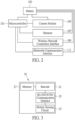
- FIG. 1 is a functional block diagram of an Internet of Things equipment management system according to a first embodiment of the present disclosure.
- an Internet of Things equipment management system IOT 1 is applicable to a first mobile terminal device MT1 used by a first user.
- the first mobile terminal device MT1 can be, for example, a mobile phone, a tablet, or a laptop computer that is network connectable, but is not limited thereto.
- the Internet of Things equipment management system IOT1 includes, for example, a client-side server CS, a first wearable camera BC1, a mobile application APP, and a first sensor S 1.
- the first mobile terminal device MT1 is network-connected to the first wearable camera BC1 and the client-side server CS, and the mobile application APP is installed in the first mobile terminal device MT1.
- the first wearable camera BC1 is worn on the body of the first user.
- the first sensor S1 is disposed on a first device D1 used by the first user.
- the first device D1 can be, for example, a police weapon or a protective device, but is not limited thereto.
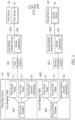
- FIG. 2 is a functional block diagram of a first wearable camera of FIG. 1 .
- the first wearable camera BC1 includes, for example, a microcontroller 101, a battery 103, a camera module 105, a memory 107, a wireless network connection interface 109, and a BLUETOOTH ® communication interface 111.
- the battery 103 is electrically connected to the microcontroller 101, the camera module 105, the memory 107, the wireless network connection interface 109, and the BLUETOOTH ® communication interface 111, so as to supply the power required for operation of the microcontroller 101, the camera module 105, the memory 107, the wireless network connection interface 109, and BLUETOOTH ® communication interface 111.
- Images or videos obtained by the camera module 105 are transmitted to the memory 107 for storage.
- FIG. 3 is a functional block diagram of a first sensor of FIG. 1 .
- the first sensor S1 may include, for example, a barcode 21, a motion sensing circuit 23, a BLUETOOTH ® communication interface 25, and a memory 27.
- the barcode 21 can be, for example, a 2D barcode or a 3D barcode, but is not limited thereto.
- the BLUETOOTH ® communication interface 25 is electrically connected to the motion sensing circuit 23 and the barcode 21, and the memory 27 is electrically connected to the barcode 21.
- the triggering of the first sensor S 1 indicates that the motion sensing circuit 23 of the first sensor S 1 detects the motion of the first device D1 and transmits a control signal to activate the BLUETOOTH ® communication interface 25.
- the BLUETOOTH ® communication interface 25 broadcasts data packets.
- the first wearable camera BC1 is network-connected to the client-side server CS, so as to receive data packets from the client-side server CS and transmit data packets to the client-side server CS.
- the first wearable camera BC1 is also network-connected to the first mobile terminal device MT1, so as to receive data packets from the first mobile terminal device MT 1 and transmit data packets to the first mobile terminal device MT1.
- the first wearable camera BC1 When the first wearable camera BC1 is turned on, the first wearable camera BC1 is network-connected to the client-side server CS. The first wearable camera BC1 obtains a first group name G1 and a first user name U1 of the first wearable camera BC1 from the client-side server CS, and stores the first group name G1 and the first user name U1 in the memory 107 of the first wearable camera BC1.
- the first mobile terminal device MT1 When being turned on, the first mobile terminal device MT1 is network-connected to the first wearable camera BC1. When the first mobile terminal device MT1 executes the mobile application APP, the mobile application APP obtains the first group name G1 from the memory 107 of the first wearable camera BC1.
- the first mobile terminal device MT1 executes the mobile application APP to scan the barcode 21 of the first sensor S 1.
- the mobile application APP scans the barcode 21 of the first sensor S 1
- the mobile application APP obtains a first serial number SN1 of the first sensor S1 from the first sensor S 1, and writes the first group name G1 of the first wearable camera BC1 to the memory 27 of the first sensor S1.
- the first mobile terminal device MT1 After the first mobile terminal device MT1 obtains the first serial number SN1 and writes the first group name G1 to the memory 27 of the first sensor S 1, the first mobile terminal device MT1 executes the mobile application APP to pair the first serial number SN1 of the first sensor S 1 and the first group name G1 of the first wearable camera BC1. In this way, a pairing relationship between the first sensor S 1 and the first wearable camera BC1 can be established.
- the mobile application APP After the mobile application APP establishes the pairing relationship between the first sensor S1 and the first wearable camera BC1, the mobile application APP transmits the pairing relationship between the first sensor S1 and the first wearable camera BC1 to the client-side server CS through a network.
- the client-side server CS When the client-side server CS receives the pairing relationship between the first sensor S1 and the first wearable camera BC1, the client-side server CS establishes a first mapping table MP1 according to the pairing relationship between the first sensor S1 and the first wearable camera BC1.
- the first mapping table MP1 includes the first serial number SN1, the first user name U1, and the first group name G1.
- the first sensor S1 broadcasts one data packet to the first wearable camera BC1 by a predetermined period.
- the data packet includes a first electric quantity information E1 of the first sensor S1.
- the first wearable camera BC1 receives the first electric quantity information E1 broadcast by the first sensor S1
- the first wearable camera BC1 transmits the first electric quantity information E1 to the client-side server CS through the network.
- the client-side server CS receives the first electric quantity information E1
- the client-side server CS writes the first electric quantity information E1 to the previously created first mapping table MP1.
- the first sensor S1 of the first device D1 is triggered.
- the BLUETOOTH ® communication interface 25 of the first sensor S1 broadcasts one data packet that includes the first group name G1, the first serial number SN1, and the first electric quantity information E1 of the first sensor S 1.
- the first wearable camera BC1 receives the data packet broadcast by the first sensor S1, a shooting function of the first wearable camera BC1 is activated.
- FIG. 4 is a functional block diagram of the Internet of Things equipment management system according to a second embodiment of the present disclosure. Differences between an Internet of Things equipment management system IOT2 and the Internet of Things equipment management system IOT 1 are illustrated below.
- the Internet of Things equipment management system IOT2 is applicable to a first mobile terminal device MT1 used by a first user, a first sensor S 1 used by the first user, a second mobile terminal device MT2 used by a second user, and a second sensor S2 used by the second user.
- Hardware architectures of the second mobile terminal device MT2 and the second sensor S2 are respectively identical to those of the first mobile terminal device MT1 and the first sensor S 1.
- the Internet of Things equipment management system IOT2 includes a client-side server CS, a first wearable camera BC1, a mobile application APP, and a second wearable camera BC2.
- the second wearable camera BC2 is worn on the body of the second user, and the hardware architecture of the second wearable camera BC2 is identical to that of the first wearable camera BC1.
- the second mobile terminal device MT2 is also installed with the mobile application APP.
- the second sensor S2 is disposed on a second device D2 used by the second user.
- the second device D2 can be, for example, a police weapon or a protective device, but is not limited thereto.
- the second wearable camera BC2 When being turned on, the second wearable camera BC2 is network-connected to the client-side server CS.
- the second wearable camera BC2 obtains a first group name G1 and a second user name U2 of the second wearable camera BC2 from the client-side server CS, and stores the first group name G1 and the second user name U2 in a memory 107 of the second wearable camera BC2.
- the second mobile terminal device MT2 When being turned on, the second mobile terminal device MT2 is network-connected to the second wearable camera BC2. When the second mobile terminal device MT2 executes the mobile application APP, the mobile application APP obtains the first group name G1 from the memory 107 of the second wearable camera BC2.
- the second mobile terminal device MT2 executes the mobile application APP to scan a barcode 21 of the second sensor S2.
- the mobile application APP scans the barcode 21 of the second sensor S2
- the mobile application APP obtains a second serial number SN2 of the second sensor S2 from the second sensor S2, and writes the first group name G1 of the second wearable camera BC2 to a memory 27 of the second sensor S2.
- the second mobile terminal device MT2 After the second mobile terminal device MT2 obtains the second serial number SN2 and writes the first group name G1 to the memory 27 of the second sensor S2, the second mobile terminal device MT2 executes the mobile application APP to pair the second serial number SN2 of the second sensor S2 with the first group name G1 of the second wearable camera BC2. In this way, a pairing relationship between the second sensor S2 and the second wearable camera BC2 can be established.
- the mobile application APP of the second mobile terminal device MT2 After the mobile application APP of the second mobile terminal device MT2 establishes the pairing relationship between the second sensor S2 and the second wearable camera BC2, the mobile application APP transmits the pairing relationship between the second sensor S2 and the second wearable camera BC2 to the client-side server CS through a network.
- the client-side server CS When the client-side server CS receives the pairing relationship between the second sensor S2 and the second wearable camera BC2, the client-side server CS establishes a second mapping table MP2 according to the pairing relationship between the second sensor S2 and the second wearable camera BC2.
- the second mapping table MP2 includes the second serial number SN2, the second user name U2, and the first group name G1.
- the second sensor S2 broadcasts one data packet to the second wearable camera BC2 by a predetermined period.
- the data packet includes a second electric quantity information E2 of the second sensor S2.
- the second wearable camera BC2 receives the second electric quantity information E2 broadcast by the second sensor S2
- the second wearable camera BC2 transmits the second electric quantity information E2 to the client-side server CS through the network.
- the client-side server CS receives the second electric quantity information E2
- the client-side server CS writes the second electric quantity information E2 to the previously created second mapping table MP2.
- the first sensor S1 on the first device D1 is triggered.
- a BLUETOOTH ® communication interface 25 of the first sensor S1 broadcasts one data packet that includes the first group name G1, a first serial number SN1, and a first electric quantity information E1 of the first sensor S1.
- both the first wearable camera BC1 and the second wearable camera BC2 receive the data packet broadcast by the first sensor S1, since the first wearable camera BC1 and the second wearable camera BC2 belong to the first group name G1, a shooting function of the first wearable camera BC1 and a shooting function of the second wearable camera BC2 can both be activated.
- the first sensor S1, the second sensor S2, the first wearable camera BC1, and the second wearable camera BC2 all belong to the first group name G1.
- the first sensor S 1 and the first wearable camera BC1 may belong to the first group name G1, while the second sensor S2 and the second wearable camera BC2 belong to the second group name.
- FIG. 5 is a flow chart of an operation method of the Internet of Things equipment management system according to one embodiment of the present disclosure.
- the operation method of the Internet of Things equipment management system in FIG. 5 can be implemented, for example, in the Internet of Things equipment management system IOT1 of FIG. 1 or in the Internet of Things equipment management system IOT2 of FIG. 4 , but is not limited thereto.
- a wearable camera is network-connected to a backend server to obtain a location of a client-side server.
- the wearable camera performs a registration process in the client-side server.
- the wearable camera obtains a group name and a user name of the wearable camera from the client-side server.
- a mobile terminal device executes a mobile application to perform the registration process in the wearable camera.
- the mobile terminal device executes the mobile application to obtain the group name from the wearable camera.
- the mobile terminal device executes the mobile application to scan a barcode of the sensor.
- step S513 the mobile application obtains a serial number of the sensor and writes the group name to the sensor.
- step S515 the mobile application pairs the serial number and the group name to establish a pairing relationship between the sensor and the wearable camera.
- step S517 the mobile application transmits the pairing relationship between the sensor and the wearable camera to the client-side server.
- step S519 the client-side server establishes a mapping table according to the pairing relationship between the sensor and the wearable camera, in which the mapping table includes the group name, the serial number, and the user name.
- FIG. 6 is an operation flow chart of the Internet of Things equipment management system of the present disclosure when the first sensor is triggered.
- a first device D1 is subject to an external force, so that a first sensor S1 is triggered.
- the first sensor S1 broadcasts a data packet that includes a first group name G1, a first serial number SN1, and first electric quantity information E1 of the first sensor S1.
- a first wearable camera BC1 and a second wearable camera BC2 both receive the data packet from the first sensor S1.
- the shooting function of the first wearable camera BC1 and the shooting function of the second wearable camera BC2 are both activated.
- step S609 the first wearable camera BC1 transmits the first electric quantity information E1 of the first sensor S1 to a client-side server CS.
- step S611 the client-side server CS writes the first electric quantity information E1 of the first sensor S1 into a first mapping table MP1.
- users can pair the wearable camera with the sensor and document relevant data in the client-side server for data management of the wearable camera and the sensor.
Landscapes
- Engineering & Computer Science (AREA)
- Business, Economics & Management (AREA)
- Physics & Mathematics (AREA)
- Theoretical Computer Science (AREA)
- Human Resources & Organizations (AREA)
- General Physics & Mathematics (AREA)
- Strategic Management (AREA)
- Tourism & Hospitality (AREA)
- Signal Processing (AREA)
- Computer Networks & Wireless Communication (AREA)
- Economics (AREA)
- Health & Medical Sciences (AREA)
- General Health & Medical Sciences (AREA)
- General Business, Economics & Management (AREA)
- Marketing (AREA)
- Entrepreneurship & Innovation (AREA)
- Development Economics (AREA)
- Educational Administration (AREA)
- Electromagnetism (AREA)
- Primary Health Care (AREA)
- Operations Research (AREA)
- Quality & Reliability (AREA)
- Computer Hardware Design (AREA)
- General Engineering & Computer Science (AREA)
- Computer Vision & Pattern Recognition (AREA)
- Toxicology (AREA)
- Artificial Intelligence (AREA)
- Data Mining & Analysis (AREA)
- Medical Informatics (AREA)
- Computing Systems (AREA)
- Game Theory and Decision Science (AREA)
- Human Computer Interaction (AREA)
- Library & Information Science (AREA)
- Databases & Information Systems (AREA)
- Computer Security & Cryptography (AREA)
- Technology Law (AREA)
- Multimedia (AREA)
- Telephonic Communication Services (AREA)
- Mobile Radio Communication Systems (AREA)
Abstract
Description
- The present disclosure relates to an Internet of Things system and an operation method thereof, and more particularly to an Internet of Things equipment management system and an operation method thereof.
- Police duties are often accompanied by potential danger, and it is necessary to document data corresponding to weapons and protective equipment on a server, so that the status of the weapons and protective equipment equipped by each policeman can be effectively managed.
- For example, according to different requirements for a mission, policemen are divided into different squads to perform a variety of tasks, and the weapons assigned to each squad may correspond to an exclusive group name in the database. For example, if 50 out of a total of 100 weapons are assigned to the policemen of a first squad during documentation of the weapons, a first group name can be designated to each of the weapons of the first squad. The remaining 50 weapons may be assigned to the policemen of a second squad, and during documentation of these weapons, a second group name can be designated for each of the weapons of the second squad.
- Due to allocation of duties, the number of squads and the weapons assigned thereto may vary. Thus, service contractors for gear documentation may need to re-designate a new group name for each weapon, which can quickly become a time-consuming burden.
- In response to the above-referenced technical inadequacy, the present disclosure provides an Internet of Things equipment management system and an operation method thereof.
- In one aspect, the present disclosure provides an Internet of Things equipment management system for a mobile terminal device. The Internet of Things equipment management system includes a client-side server, a first wearable camera, a mobile application, and a sensor. The first wearable camera is connected to the client-side server through a network and obtains a group name and a user name of the first wearable camera from the client-side server. The mobile application is installed in the mobile terminal device. The sensor has a barcode. The mobile application is configured to: obtain the group name from the first wearable camera; scan the barcode to obtain a serial number from the sensor and write the group name to the sensor; pair the group name and the serial number to establish a pairing relationship between the first wearable camera and the sensor; and transmit the pairing relationship to the client-side server for establishing, by the client-side server, a mapping table according to the pairing relationship, and the mapping table includes the user name, the group name, and the serial number.
- In another aspect, the present disclosure provides an Internet of Things equipment management system for a mobile terminal device and a sensor having a barcode. The Internet of Things equipment management system includes a client-side server, a first wearable camera, and a mobile application. The first wearable camera is connected to the client-side server through a network and obtains a group name and a user name of the first wearable camera from the client-side server. The mobile application is installed in the mobile terminal device. The mobile application is configured to: obtain the group name from the first wearable camera; scan the barcode to obtain a serial number from the sensor and write the group name to the sensor; pair the group name and the serial number to establish a pairing relationship between the first wearable camera and the sensor; and transmit the pairing relationship to the client-side server for establishing, by the client-side server, a mapping table according to the pairing relationship, and the mapping table includes the user name, the group name, and the serial number.
- In yet another aspect, the present disclosure provides an operation method of an Internet of Things equipment management system, which includes: obtaining, by a wearable camera, a group name and a user name of the wearable camera from a client-side server; obtaining, by a mobile application of a mobile terminal device, the group name from the wearable camera; scanning a barcode of a sensor to obtain a serial number of the sensor and writing the group name into the sensor by the mobile application; pairing, by the mobile application, the group name and the serial number to establish a pairing relationship between the wearable camera and the sensor; transmitting, by the mobile application, the pairing relationship to the client-side server; and establishing, by the client-side server, a mapping table according to the pairing relationship with the client-side server. The mapping table includes the user name, the group name, and the serial number.
- Therefore, in the Internet of Things equipment management system and the operation method thereof provided by the present disclosure, users can pair the wearable camera with the sensor and document relevant data in the client-side server for data management of the wearable camera and the sensor.
- These and other aspects of the present disclosure will become apparent from the following description of the embodiment taken in conjunction with the following drawings and their captions, although variations and modifications therein may be affected without departing from the spirit and scope of the novel concepts of the disclosure.
- The described embodiments may be better understood by reference to the following description and the accompanying drawings, in which:
-
FIG. 1 is a functional block diagram of an Internet of Things equipment management system according to a first embodiment of the present disclosure; -
FIG. 2 is a functional block diagram of a first wearable camera ofFIG. 1 ; -
FIG. 3 is a functional block diagram of a first sensor ofFIG. 1 ; -
FIG. 4 is a functional block diagram of the Internet of Things equipment management system according to a second embodiment of the present disclosure; -
FIG. 5 is a flow chart of an operation method of the Internet of Things equipment management system according to one embodiment of the present disclosure; and -
FIG. 6 is an operation flow chart of the Internet of Things equipment management system of the present disclosure when the first sensor is triggered. - The present disclosure is more particularly described in the following examples that are intended as illustrative only since numerous modifications and variations therein will be apparent to those skilled in the art. Like numbers in the drawings indicate like components throughout the views. As used in the description herein and throughout the claims that follow, unless the context clearly dictates otherwise, the meaning of "a", "an", and "the" includes plural reference, and the meaning of "in" includes "in" and "on". Titles or subtitles can be used herein for the convenience of a reader, which shall have no influence on the scope of the present disclosure.
- The terms used herein generally have their ordinary meanings in the art. In the case of conflict, the present document, including any definitions given herein, will prevail. The same thing can be expressed in more than one way. Alternative language and synonyms can be used for any term(s) discussed herein, and no special significance is to be placed upon whether a term is elaborated or discussed herein. A recital of one or more synonyms does not exclude the use of other synonyms. The use of examples anywhere in this specification including examples of any terms is illustrative only, and in no way limits the scope and meaning of the present disclosure or of any exemplified term. Likewise, the present disclosure is not limited to various embodiments given herein. Numbering terms such as "first", "second" or "third" can be used to describe various components, signals or the like, which are for distinguishing one component/signal from another one only, and are not intended to, nor should be construed to impose any substantive limitations on the components, signals or the like.
-
FIG. 1 is a functional block diagram of an Internet of Things equipment management system according to a first embodiment of the present disclosure. As shown inFIG. 1 , an Internet of Things equipmentmanagement system IOT 1 is applicable to a first mobile terminal device MT1 used by a first user. The first mobile terminal device MT1 can be, for example, a mobile phone, a tablet, or a laptop computer that is network connectable, but is not limited thereto. - The Internet of Things equipment management system IOT1 includes, for example, a client-side server CS, a first wearable camera BC1, a mobile application APP, and a
first sensor S 1. The first mobile terminal device MT1 is network-connected to the first wearable camera BC1 and the client-side server CS, and the mobile application APP is installed in the first mobile terminal device MT1. The first wearable camera BC1 is worn on the body of the first user. The first sensor S1 is disposed on a first device D1 used by the first user. The first device D1 can be, for example, a police weapon or a protective device, but is not limited thereto. -
FIG. 2 is a functional block diagram of a first wearable camera ofFIG. 1 . As shown inFIG. 2 , the first wearable camera BC1 includes, for example, amicrocontroller 101, abattery 103, acamera module 105, amemory 107, a wirelessnetwork connection interface 109, and a BLUETOOTH®communication interface 111. Thebattery 103 is electrically connected to themicrocontroller 101, thecamera module 105, thememory 107, the wirelessnetwork connection interface 109, and the BLUETOOTH®communication interface 111, so as to supply the power required for operation of themicrocontroller 101, thecamera module 105, thememory 107, the wirelessnetwork connection interface 109, and BLUETOOTH®communication interface 111. Images or videos obtained by thecamera module 105 are transmitted to thememory 107 for storage. -
FIG. 3 is a functional block diagram of a first sensor ofFIG. 1 . The first sensor S1 may include, for example, abarcode 21, amotion sensing circuit 23, a BLUETOOTH®communication interface 25, and amemory 27. Thebarcode 21 can be, for example, a 2D barcode or a 3D barcode, but is not limited thereto. The BLUETOOTH®communication interface 25 is electrically connected to themotion sensing circuit 23 and thebarcode 21, and thememory 27 is electrically connected to thebarcode 21. When the first device D1 is subject to an external force and generates a motion, thefirst sensor S 1 is triggered. The triggering of thefirst sensor S 1 indicates that themotion sensing circuit 23 of thefirst sensor S 1 detects the motion of the first device D1 and transmits a control signal to activate the BLUETOOTH® communication interface 25. When being activated, the BLUETOOTH® communication interface 25 broadcasts data packets. - The first wearable camera BC1 is network-connected to the client-side server CS, so as to receive data packets from the client-side server CS and transmit data packets to the client-side server CS. The first wearable camera BC1 is also network-connected to the first mobile terminal device MT1, so as to receive data packets from the first mobile
terminal device MT 1 and transmit data packets to the first mobile terminal device MT1. - When the first wearable camera BC1 is turned on, the first wearable camera BC1 is network-connected to the client-side server CS. The first wearable camera BC1 obtains a first group name G1 and a first user name U1 of the first wearable camera BC1 from the client-side server CS, and stores the first group name G1 and the first user name U1 in the
memory 107 of the first wearable camera BC1. - When being turned on, the first mobile terminal device MT1 is network-connected to the first wearable camera BC1. When the first mobile terminal device MT1 executes the mobile application APP, the mobile application APP obtains the first group name G1 from the
memory 107 of the first wearable camera BC1. - The first mobile terminal device MT1 executes the mobile application APP to scan the
barcode 21 of thefirst sensor S 1. When the mobile application APP scans thebarcode 21 of thefirst sensor S 1, the mobile application APP obtains a first serial number SN1 of the first sensor S1 from thefirst sensor S 1, and writes the first group name G1 of the first wearable camera BC1 to thememory 27 of the first sensor S1. - After the first mobile terminal device MT1 obtains the first serial number SN1 and writes the first group name G1 to the
memory 27 of thefirst sensor S 1, the first mobile terminal device MT1 executes the mobile application APP to pair the first serial number SN1 of thefirst sensor S 1 and the first group name G1 of the first wearable camera BC1. In this way, a pairing relationship between thefirst sensor S 1 and the first wearable camera BC1 can be established. - After the mobile application APP establishes the pairing relationship between the first sensor S1 and the first wearable camera BC1, the mobile application APP transmits the pairing relationship between the first sensor S1 and the first wearable camera BC1 to the client-side server CS through a network.
- When the client-side server CS receives the pairing relationship between the first sensor S1 and the first wearable camera BC1, the client-side server CS establishes a first mapping table MP1 according to the pairing relationship between the first sensor S1 and the first wearable camera BC1. The first mapping table MP1 includes the first serial number SN1, the first user name U1, and the first group name G1.
- Moreover, after the client-side server CS establishes the first mapping table MP1, the first sensor S1 broadcasts one data packet to the first wearable camera BC1 by a predetermined period. The data packet includes a first electric quantity information E1 of the first sensor S1. When the first wearable camera BC1 receives the first electric quantity information E1 broadcast by the first sensor S1, the first wearable camera BC1 transmits the first electric quantity information E1 to the client-side server CS through the network. When the client-side server CS receives the first electric quantity information E1, the client-side server CS writes the first electric quantity information E1 to the previously created first mapping table MP1.
- In addition, when the first device D1 is subject to an external force and generates a motion, the first sensor S1 of the first device D1 is triggered. When the first sensor S1 is triggered, the BLUETOOTH® communication interface 25 of the first sensor S1 broadcasts one data packet that includes the first group name G1, the first serial number SN1, and the first electric quantity information E1 of the
first sensor S 1. When the first wearable camera BC1 receives the data packet broadcast by the first sensor S1, a shooting function of the first wearable camera BC1 is activated. -
FIG. 4 is a functional block diagram of the Internet of Things equipment management system according to a second embodiment of the present disclosure. Differences between an Internet of Things equipment management system IOT2 and the Internet of Things equipmentmanagement system IOT 1 are illustrated below. - As shown in
FIG. 4 , the Internet of Things equipment management system IOT2 is applicable to a first mobile terminal device MT1 used by a first user, afirst sensor S 1 used by the first user, a second mobile terminal device MT2 used by a second user, and a second sensor S2 used by the second user. Hardware architectures of the second mobile terminal device MT2 and the second sensor S2 are respectively identical to those of the first mobile terminal device MT1 and thefirst sensor S 1. - The Internet of Things equipment management system IOT2 includes a client-side server CS, a first wearable camera BC1, a mobile application APP, and a second wearable camera BC2. The second wearable camera BC2 is worn on the body of the second user, and the hardware architecture of the second wearable camera BC2 is identical to that of the first wearable camera BC1. The second mobile terminal device MT2 is also installed with the mobile application APP. The second sensor S2 is disposed on a second device D2 used by the second user. The second device D2 can be, for example, a police weapon or a protective device, but is not limited thereto.
- When being turned on, the second wearable camera BC2 is network-connected to the client-side server CS. The second wearable camera BC2 obtains a first group name G1 and a second user name U2 of the second wearable camera BC2 from the client-side server CS, and stores the first group name G1 and the second user name U2 in a
memory 107 of the second wearable camera BC2. - When being turned on, the second mobile terminal device MT2 is network-connected to the second wearable camera BC2. When the second mobile terminal device MT2 executes the mobile application APP, the mobile application APP obtains the first group name G1 from the
memory 107 of the second wearable camera BC2. - The second mobile terminal device MT2 executes the mobile application APP to scan a
barcode 21 of the second sensor S2. When the mobile application APP scans thebarcode 21 of the second sensor S2, the mobile application APP obtains a second serial number SN2 of the second sensor S2 from the second sensor S2, and writes the first group name G1 of the second wearable camera BC2 to amemory 27 of the second sensor S2. - After the second mobile terminal device MT2 obtains the second serial number SN2 and writes the first group name G1 to the
memory 27 of the second sensor S2, the second mobile terminal device MT2 executes the mobile application APP to pair the second serial number SN2 of the second sensor S2 with the first group name G1 of the second wearable camera BC2. In this way, a pairing relationship between the second sensor S2 and the second wearable camera BC2 can be established. - After the mobile application APP of the second mobile terminal device MT2 establishes the pairing relationship between the second sensor S2 and the second wearable camera BC2, the mobile application APP transmits the pairing relationship between the second sensor S2 and the second wearable camera BC2 to the client-side server CS through a network.
- When the client-side server CS receives the pairing relationship between the second sensor S2 and the second wearable camera BC2, the client-side server CS establishes a second mapping table MP2 according to the pairing relationship between the second sensor S2 and the second wearable camera BC2. The second mapping table MP2 includes the second serial number SN2, the second user name U2, and the first group name G1.
- Moreover, after the client-side server CS establishes the second mapping table MP2, the second sensor S2 broadcasts one data packet to the second wearable camera BC2 by a predetermined period. The data packet includes a second electric quantity information E2 of the second sensor S2. When the second wearable camera BC2 receives the second electric quantity information E2 broadcast by the second sensor S2, the second wearable camera BC2 transmits the second electric quantity information E2 to the client-side server CS through the network. When the client-side server CS receives the second electric quantity information E2, the client-side server CS writes the second electric quantity information E2 to the previously created second mapping table MP2.
- In addition, when a first device D1 is subject to an external force and generates a motion, the first sensor S1 on the first device D1 is triggered. When the first sensor S1 is triggered, a BLUETOOTH® communication interface 25 of the first sensor S1 broadcasts one data packet that includes the first group name G1, a first serial number SN1, and a first electric quantity information E1 of the first sensor S1. When both the first wearable camera BC1 and the second wearable camera BC2 receive the data packet broadcast by the first sensor S1, since the first wearable camera BC1 and the second wearable camera BC2 belong to the first group name G1, a shooting function of the first wearable camera BC1 and a shooting function of the second wearable camera BC2 can both be activated.
- In the Internet of Things equipment management system IOT2 shown in
FIG. 4 , the first sensor S1, the second sensor S2, the first wearable camera BC1, and the second wearable camera BC2 all belong to the first group name G1. However, in other embodiments, thefirst sensor S 1 and the first wearable camera BC1 may belong to the first group name G1, while the second sensor S2 and the second wearable camera BC2 belong to the second group name. -
FIG. 5 is a flow chart of an operation method of the Internet of Things equipment management system according to one embodiment of the present disclosure. The operation method of the Internet of Things equipment management system inFIG. 5 can be implemented, for example, in the Internet of Things equipment management system IOT1 ofFIG. 1 or in the Internet of Things equipment management system IOT2 ofFIG. 4 , but is not limited thereto. - As shown in
FIG. 5 , in step S501, a wearable camera is network-connected to a backend server to obtain a location of a client-side server. In step S503, the wearable camera performs a registration process in the client-side server. In step S505, the wearable camera obtains a group name and a user name of the wearable camera from the client-side server. In step S507, a mobile terminal device executes a mobile application to perform the registration process in the wearable camera. In step S509, the mobile terminal device executes the mobile application to obtain the group name from the wearable camera. In step S511, the mobile terminal device executes the mobile application to scan a barcode of the sensor. In step S513, the mobile application obtains a serial number of the sensor and writes the group name to the sensor. In step S515, the mobile application pairs the serial number and the group name to establish a pairing relationship between the sensor and the wearable camera. In step S517, the mobile application transmits the pairing relationship between the sensor and the wearable camera to the client-side server. In step S519, the client-side server establishes a mapping table according to the pairing relationship between the sensor and the wearable camera, in which the mapping table includes the group name, the serial number, and the user name. -
FIG. 6 is an operation flow chart of the Internet of Things equipment management system of the present disclosure when the first sensor is triggered. As shown inFIG. 6 , in step S601, a first device D1 is subject to an external force, so that a first sensor S1 is triggered. In step S603, the first sensor S1 broadcasts a data packet that includes a first group name G1, a first serial number SN1, and first electric quantity information E1 of the first sensor S1. In step S605, a first wearable camera BC1 and a second wearable camera BC2 both receive the data packet from the first sensor S1. In step S607, the shooting function of the first wearable camera BC1 and the shooting function of the second wearable camera BC2 are both activated. In step S609, the first wearable camera BC1 transmits the first electric quantity information E1 of the first sensor S1 to a client-side server CS. In step S611, the client-side server CS writes the first electric quantity information E1 of the first sensor S1 into a first mapping table MP1. - In conclusion, in the Internet of Things equipment management system and the operation method thereof provided by the present disclosure, users can pair the wearable camera with the sensor and document relevant data in the client-side server for data management of the wearable camera and the sensor.
- The foregoing description of the exemplary embodiments of the disclosure has been presented only for the purposes of illustration and description and is not intended to be exhaustive or to limit the disclosure to the precise forms disclosed. Many modifications and variations are possible in light of the above teaching.
- The embodiments were chosen and described in order to explain the principles of the disclosure and their practical application so as to enable others skilled in the art to utilize the disclosure and various embodiments and with various modifications as are suited to the particular use contemplated. Alternative embodiments will become apparent to those skilled in the art to which the present disclosure pertains without departing from its spirit and scope.
Claims (12)
- An Internet of Things equipment management system (IOT1, IOT2) for a mobile terminal device, characterized in that the Internet of Things equipment management system (IOT1, IOT2) comprising:a client-side server (CS);a first wearable camera (BC1) network-connected to the client-side server (CS) and obtaining a group name and a user name of the first wearable camera (BC1) from the client-side server (CS);a mobile application (APP) installed in the mobile terminal device; anda sensor having a barcode (21);wherein the mobile application (APP) is configured to:obtain the group name from the first wearable camera (BC1);scan the barcode (21) to obtain a serial number from the sensor and write the group name to the sensor;pair the group name and the serial number to establish a pairing relationship between the first wearable camera (BC1) and the sensor; andtransmit the pairing relationship to the client-side server (CS) for establishing, by the client-side server (CS), a mapping table according to the pairing relationship;wherein the mapping table includes the user name, the group name, and the serial number.
- The Internet of Things equipment management system (IOT1, IOT2) according to claim 1, wherein, when the sensor is triggered, the sensor sends a data packet, and the data packet includes the serial number, the group name, and electric quantity information of the sensor; wherein, after the first wearable camera (BC1) reads the data packet, a shooting function of the first wearable camera (BC1) is activated.
- The Internet of Things equipment management system (IOT1, IOT2) according to claim 2, wherein the sensor includes a motion sensing circuit (23) and a BLUETOOTH® communication interface electrically connected to the motion sensing circuit (23); wherein, when the motion sensing circuit (23) detects a motion, the BLUETOOTH® communication interface broadcasts the data packet.
- The Internet of Things equipment management system (IOT1, IOT2) according to claim 1, further comprising a second wearable camera (BC2), a group name of the second wearable camera (BC2) being identical to the group name of the first wearable camera (BC1);
wherein, when the sensor is triggered, the sensor broadcasts a data packet, and the data packet includes the serial number, the group name, and electric quantity information of the sensor; wherein, after the data packet is read by the first wearable camera (BC1) and the second wearable camera (BC2), a shooting function of the first wearable camera (BC1) and a shooting function of the second wearable camera (BC2) are activated. - An Internet of Things equipment management system (IOT1, IOT2) for a mobile terminal device and a sensor having a barcode (21), characterized in that the Internet of Things equipment management system (IOT1, IOT2) comprising:a client-side server (CS);a first wearable camera (BC1) network-connected to the client-side server (CS) and obtaining a group name and a user name of the first wearable camera (BC1) from the client-side server (CS); anda mobile application (APP) installed in the mobile terminal device;wherein the mobile application (APP) is configured to:obtain the group name from the first wearable camera (BC1);scan the barcode (21) to obtain a serial number from the sensor and write the group name to the sensor;pair the group name and the serial number to establish a pairing relationship between the first wearable camera (BC1) and the sensor; andtransmit the pairing relationship to the client-side server (CS) for establishing, by the client-side server (CS), a mapping table according to the pairing relationship;wherein the mapping table includes the user name, the group name, and the serial number.
- The Internet of Things equipment management system (IOT1, IOT2) according to claim 5, wherein, when the sensor is triggered, the sensor broadcasts a data packet, and the data packet includes the serial number, the group name, and electric quantity information of the sensor; wherein, after the data packet is read by the first wearable camera (BC1), a shooting function of the first wearable camera (BC1) is activated.
- The Internet of Things equipment management system (IOT1, IOT2) according to claim 6, wherein the sensor includes a motion sensing circuit (23) and a BLUETOOTH® communication interface (111) electrically connected to the motion sensing circuit (23); wherein, when the motion sensing circuit (23) detects a motion, the BLUETOOTH® communication interface (111) broadcasts the data packet.
- The Internet of Things equipment management system (IOT1, IOT2) according to claim 6, further comprising a second wearable camera (BC2), a group name of the second wearable camera (BC2) being identical to the group name of the first wearable camera (BC1);
wherein, when the sensor is triggered, the sensor broadcasts a data packet, and the data packet includes the serial number, the group name, and electric quantity information of the sensor; wherein, after the data packet is read by the first wearable camera (BC1) and the second wearable camera (BC2), a shooting function of the first wearable camera (BC1) and a shooting function of the second wearable camera (BC2) are activated. - An operation method of an Internet of Things equipment management system (IOT1, IOT2), characterized in that the operation method comprising:obtaining, by a wearable camera, a group name and a user name of the wearable camera from a client-side server (CS);obtaining, by a mobile application (APP) of a mobile terminal device, the group name from the wearable camera;scanning a barcode (21) of a sensor to obtain a serial number of the sensor and writing the group name into the sensor by the mobile application (APP);pairing, by the mobile application (APP), the group name and the serial number to establish a pairing relationship between the wearable camera and the sensor;transmitting, by the mobile application (APP), the pairing relationship to the client-side server (CS); andestablishing, by the client-side server (CS), a mapping table according to the pairing relationship, wherein the mapping table includes the user name, the group name, and the serial number.
- The operation method according to claim 9, further comprising:configuring the wearable camera to be network-connected to a backend server to obtain a location of the client-side server (CS) before the group name and the user name are obtained from the client-side server (CS); andperforming, by the wearable camera, a registration process in the client-side server (CS) after the location of the client-side server (CS) is obtained.
- The operation method according to claim 9, further comprising:
performing, by the mobile application (APP), a registration process in the wearable camera after the group name and the user name are obtained from the client-side server (CS) and before the group name is obtained from the wearable camera. - The operation method according to claim 9, further comprising:
broadcasting, by the sensor, a data packet to the wearable camera when the sensor is triggered, wherein the data packet includes the group name, the serial number, and electric quantity information of the sensor; wherein, after the wearable camera reads the data packet, a shooting function of the wearable camera is activated.
Applications Claiming Priority (1)
| Application Number | Priority Date | Filing Date | Title |
|---|---|---|---|
| CN202211424132.8A CN118101358A (en) | 2022-11-15 | 2022-11-15 | Internet of things equipment management system and operation method thereof |
Publications (2)
| Publication Number | Publication Date |
|---|---|
| EP4373058A1 true EP4373058A1 (en) | 2024-05-22 |
| EP4373058B1 EP4373058B1 (en) | 2025-11-12 |
Family
ID=85571256
Family Applications (1)
| Application Number | Title | Priority Date | Filing Date |
|---|---|---|---|
| EP23160965.2A Active EP4373058B1 (en) | 2022-11-15 | 2023-03-09 | Internet of things equipment management system and operation method thereof |
Country Status (5)
| Country | Link |
|---|---|
| US (1) | US11954558B1 (en) |
| EP (1) | EP4373058B1 (en) |
| CN (1) | CN118101358A (en) |
| AU (1) | AU2023201446B2 (en) |
| PL (1) | PL4373058T3 (en) |
Families Citing this family (1)
| Publication number | Priority date | Publication date | Assignee | Title |
|---|---|---|---|---|
| CN118057406A (en) * | 2022-11-15 | 2024-05-21 | 神基科技股份有限公司 | Internet of things equipment management system and operation method thereof |
Citations (1)
| Publication number | Priority date | Publication date | Assignee | Title |
|---|---|---|---|---|
| US20180314861A1 (en) * | 2017-04-28 | 2018-11-01 | Whp Workflow Solutions, Inc. | Device control using entity identifiers |
Family Cites Families (19)
| Publication number | Priority date | Publication date | Assignee | Title |
|---|---|---|---|---|
| US10073953B2 (en) * | 2002-10-01 | 2018-09-11 | World Award Academy, World Award Foundation, Amobilepay, Inc. | Wearable personal digital device for facilitating mobile device payments and personal use |
| US9853826B2 (en) | 2013-02-25 | 2017-12-26 | Qualcomm Incorporated | Establishing groups of internet of things (IOT) devices and enabling communication among the groups of IOT devices |
| US9451462B2 (en) | 2014-08-10 | 2016-09-20 | Belkin International Inc. | Setup of multiple IoT network devices |
| US10192277B2 (en) | 2015-07-14 | 2019-01-29 | Axon Enterprise, Inc. | Systems and methods for generating an audit trail for auditable devices |
| TWI579758B (en) | 2016-01-29 | 2017-04-21 | 物聯智慧科技(深圳)有限公司 | User Electronic Device, User Interface And Computer Program Product |
| CA3031253A1 (en) * | 2016-07-21 | 2018-01-25 | Clinical Biotechnology Research Institute At Rsfh | Container tracking system |
| US10511801B2 (en) | 2016-08-24 | 2019-12-17 | Whp Workflow Solutions, Inc. | Portable recording device multimedia classification system |
| US10110272B2 (en) * | 2016-08-24 | 2018-10-23 | Centurylink Intellectual Property Llc | Wearable gesture control device and method |
| US11665758B2 (en) | 2017-05-01 | 2023-05-30 | Axon Enterprise, Inc. | Systems and methods for dynamic pairing of electronic devices |
| US10887189B2 (en) | 2017-08-03 | 2021-01-05 | Dish Network L.L.C. | Systems and methods of mapping connected devices |
| TWI663580B (en) | 2017-12-01 | 2019-06-21 | Getac Technology Corporation | A control method of surveillance system |
| US11075709B2 (en) * | 2018-02-15 | 2021-07-27 | Qualcomm Incorporated | Variable spreading factor codes for non-orthogonal multiple access |
| US10862756B2 (en) * | 2018-03-22 | 2020-12-08 | Citrix Systems, Inc. | Systems and methods for inventory discovery in a network |
| US11471052B2 (en) | 2019-05-29 | 2022-10-18 | Dexcom, Inc. | System and method for wireless communication of analyte data |
| US11520677B1 (en) * | 2019-09-25 | 2022-12-06 | Aimcast Ip, Llc | Real-time Iot device reliability and maintenance system and method |
| KR102929039B1 (en) * | 2019-10-18 | 2026-02-20 | 삼성전자주식회사 | Method and apparatus for key storing and recovery for blockchain based system |
| US20210311987A1 (en) | 2020-04-07 | 2021-10-07 | Motorola Solutions, Inc. | Digital assistant word choice |
| US12028709B2 (en) | 2020-05-04 | 2024-07-02 | Getac Technology Corporation | Remote triggering of events by personal devices |
| US11461991B2 (en) * | 2020-12-30 | 2022-10-04 | Imagine Technologies, Inc. | Method of developing a database of controllable objects in an environment |
-
2022
- 2022-11-15 CN CN202211424132.8A patent/CN118101358A/en active Pending
-
2023
- 2023-01-17 US US18/155,695 patent/US11954558B1/en active Active
- 2023-03-08 AU AU2023201446A patent/AU2023201446B2/en active Active
- 2023-03-09 PL PL23160965.2T patent/PL4373058T3/en unknown
- 2023-03-09 EP EP23160965.2A patent/EP4373058B1/en active Active
Patent Citations (1)
| Publication number | Priority date | Publication date | Assignee | Title |
|---|---|---|---|---|
| US20180314861A1 (en) * | 2017-04-28 | 2018-11-01 | Whp Workflow Solutions, Inc. | Device control using entity identifiers |
Non-Patent Citations (2)
| Title |
|---|
| MOTOROLA: "VB400 BODY-WORN CAMERA BROCHURE", WWW.MOTOROLASOLUTIONS.COM, 31 December 2020 (2020-12-31), Motorola Solutions Ltd. Nova South, 160 Victoria Street, London, SW1E 5LB, United Kingdom, pages 1 - 8, XP093075767, Retrieved from the Internet <URL:https://www.motorolasolutions.com/content/dam/msi/docs/EA_Collaterals/ENGLISH/bwc/vb400_brochure_eng.pdf?elqTrackId=737325606b9d4806a76e9301cb18e036&elqaid=6177&elqat=2&_gl=1*1cacrrg*_ga*OTEzNDQ2OTIxLjE2OTI3NzkwODA.*_ga_23THW5EV9N*MTY5Mjc3OTA4MC4xLjEuMTY5Mjc4MDE5MS42MC4wLjA.> [retrieved on 20230823] * |
| SAMSUNG: "Mobile barcode scanner", 31 December 2020 (2020-12-31), pages 1 - 2, XP093069517, Retrieved from the Internet <URL:https://image-us.samsung.com/SamsungUS/samsungbusiness/solutions/industries/transportation/field-service-solutions/11232020/SE-7284-20-HHP-MFG-XCOVERPRO-KOAMTACSCANNER-FLYER-JUL20T_C14.pdf> [retrieved on 20230801] * |
Also Published As
| Publication number | Publication date |
|---|---|
| CN118101358A (en) | 2024-05-28 |
| PL4373058T3 (en) | 2026-03-09 |
| AU2023201446A1 (en) | 2024-05-30 |
| US11954558B1 (en) | 2024-04-09 |
| AU2023201446B2 (en) | 2025-01-30 |
| EP4373058B1 (en) | 2025-11-12 |
Similar Documents
| Publication | Publication Date | Title |
|---|---|---|
| US10887745B2 (en) | Method and device for sharing file between different terminals | |
| CN103596160B (en) | Method and device for data transmission | |
| EP1833230A1 (en) | Wireless communication device, MAC address management system, wireless communication method, and program | |
| KR20190106913A (en) | Electronic device using an augmented reality | |
| DE10253923A1 (en) | Digital camera that has an image transmission method and system | |
| US20180343231A1 (en) | Communication device, address configuration method, and recording medium | |
| JP2013157744A (en) | Mobile terminal, control method, and program | |
| EP4373058B1 (en) | Internet of things equipment management system and operation method thereof | |
| CN106327159A (en) | Attendance system and attendance system control method | |
| EP4373057A1 (en) | Internet of things equipment management system and operation method thereof | |
| HK1221852A1 (en) | Electronic business card exchange method, device and system | |
| EP3226513A1 (en) | Network-based file transfer method and system | |
| KR101716183B1 (en) | Network camera and surveillance system includint the same | |
| WO2019084742A1 (en) | Data transmission method, server, storage system, terminal device, and system | |
| CN110768749B (en) | Data transmission method and device and power peak shaving system | |
| EP3364694A1 (en) | Network element selection method and network element selector | |
| CN107818672A (en) | A kind of method and apparatus for controlling aircraft | |
| US11803494B2 (en) | Data communication method, master device and system | |
| CN109246232A (en) | Data transmission method, system and device | |
| US20200065508A1 (en) | Device and method to share image received from user terminal with other user terminals | |
| TW202423168A (en) | Internet of things equipment management system and operation method thereof | |
| CN113438266B (en) | Method, device, equipment and storage medium for acquiring data of wearable massager | |
| US8843137B2 (en) | Femtocell radio base station, communication control method, and recording medium | |
| WO2013095052A1 (en) | Method and apparatus for providing contents in communication system | |
| TW202423169A (en) | Internet of things equipment management system and operation method thereof |
Legal Events
| Date | Code | Title | Description |
|---|---|---|---|
| PUAI | Public reference made under article 153(3) epc to a published international application that has entered the european phase |
Free format text: ORIGINAL CODE: 0009012 |
|
| STAA | Information on the status of an ep patent application or granted ep patent |
Free format text: STATUS: THE APPLICATION HAS BEEN PUBLISHED |
|
| AK | Designated contracting states |
Kind code of ref document: A1 Designated state(s): AL AT BE BG CH CY CZ DE DK EE ES FI FR GB GR HR HU IE IS IT LI LT LU LV MC ME MK MT NL NO PL PT RO RS SE SI SK SM TR |
|
| STAA | Information on the status of an ep patent application or granted ep patent |
Free format text: STATUS: REQUEST FOR EXAMINATION WAS MADE |
|
| 17P | Request for examination filed |
Effective date: 20240912 |
|
| RBV | Designated contracting states (corrected) |
Designated state(s): AL AT BE BG CH CY CZ DE DK EE ES FI FR GB GR HR HU IE IS IT LI LT LU LV MC ME MK MT NL NO PL PT RO RS SE SI SK SM TR |
|
| GRAP | Despatch of communication of intention to grant a patent |
Free format text: ORIGINAL CODE: EPIDOSNIGR1 |
|
| STAA | Information on the status of an ep patent application or granted ep patent |
Free format text: STATUS: GRANT OF PATENT IS INTENDED |
|
| INTG | Intention to grant announced |
Effective date: 20250703 |
|
| GRAS | Grant fee paid |
Free format text: ORIGINAL CODE: EPIDOSNIGR3 |
|
| GRAA | (expected) grant |
Free format text: ORIGINAL CODE: 0009210 |
|
| STAA | Information on the status of an ep patent application or granted ep patent |
Free format text: STATUS: THE PATENT HAS BEEN GRANTED |
|
| AK | Designated contracting states |
Kind code of ref document: B1 Designated state(s): AL AT BE BG CH CY CZ DE DK EE ES FI FR GB GR HR HU IE IS IT LI LT LU LV MC ME MK MT NL NO PL PT RO RS SE SI SK SM TR |
|
| REG | Reference to a national code |
Ref country code: CH Ref legal event code: F10 Free format text: ST27 STATUS EVENT CODE: U-0-0-F10-F00 (AS PROVIDED BY THE NATIONAL OFFICE) Effective date: 20251112 Ref country code: GB Ref legal event code: FG4D |
|
| REG | Reference to a national code |
Ref country code: IE Ref legal event code: FG4D |
|
| REG | Reference to a national code |
Ref country code: DE Ref legal event code: R096 Ref document number: 602023008429 Country of ref document: DE |
|
| REG | Reference to a national code |
Ref country code: NL Ref legal event code: MP Effective date: 20251112 |
|
| PG25 | Lapsed in a contracting state [announced via postgrant information from national office to epo] |
Ref country code: ES Free format text: LAPSE BECAUSE OF FAILURE TO SUBMIT A TRANSLATION OF THE DESCRIPTION OR TO PAY THE FEE WITHIN THE PRESCRIBED TIME-LIMIT Effective date: 20251112 |
|
| REG | Reference to a national code |
Ref country code: LT Ref legal event code: MG9D |
|
| PG25 | Lapsed in a contracting state [announced via postgrant information from national office to epo] |
Ref country code: NO Free format text: LAPSE BECAUSE OF FAILURE TO SUBMIT A TRANSLATION OF THE DESCRIPTION OR TO PAY THE FEE WITHIN THE PRESCRIBED TIME-LIMIT Effective date: 20260212 |
|
| PGFP | Annual fee paid to national office [announced via postgrant information from national office to epo] |
Ref country code: DE Payment date: 20260305 Year of fee payment: 4 |
|
| PG25 | Lapsed in a contracting state [announced via postgrant information from national office to epo] |
Ref country code: FI Free format text: LAPSE BECAUSE OF FAILURE TO SUBMIT A TRANSLATION OF THE DESCRIPTION OR TO PAY THE FEE WITHIN THE PRESCRIBED TIME-LIMIT Effective date: 20251112 Ref country code: HR Free format text: LAPSE BECAUSE OF FAILURE TO SUBMIT A TRANSLATION OF THE DESCRIPTION OR TO PAY THE FEE WITHIN THE PRESCRIBED TIME-LIMIT Effective date: 20251112 Ref country code: AT Free format text: LAPSE BECAUSE OF FAILURE TO SUBMIT A TRANSLATION OF THE DESCRIPTION OR TO PAY THE FEE WITHIN THE PRESCRIBED TIME-LIMIT Effective date: 20251112 |
|
| PGFP | Annual fee paid to national office [announced via postgrant information from national office to epo] |
Ref country code: AT Payment date: 20260301 Year of fee payment: 4 |
|
| REG | Reference to a national code |
Ref country code: AT Ref legal event code: MK05 Ref document number: 1857788 Country of ref document: AT Kind code of ref document: T Effective date: 20251112 |
|
| PG25 | Lapsed in a contracting state [announced via postgrant information from national office to epo] |
Ref country code: NL Free format text: LAPSE BECAUSE OF FAILURE TO SUBMIT A TRANSLATION OF THE DESCRIPTION OR TO PAY THE FEE WITHIN THE PRESCRIBED TIME-LIMIT Effective date: 20251112 |
|
| PG25 | Lapsed in a contracting state [announced via postgrant information from national office to epo] |
Ref country code: RS Free format text: LAPSE BECAUSE OF FAILURE TO SUBMIT A TRANSLATION OF THE DESCRIPTION OR TO PAY THE FEE WITHIN THE PRESCRIBED TIME-LIMIT Effective date: 20260212 |
|
| PG25 | Lapsed in a contracting state [announced via postgrant information from national office to epo] |
Ref country code: IS Free format text: LAPSE BECAUSE OF FAILURE TO SUBMIT A TRANSLATION OF THE DESCRIPTION OR TO PAY THE FEE WITHIN THE PRESCRIBED TIME-LIMIT Effective date: 20260312 |
|
| PGFP | Annual fee paid to national office [announced via postgrant information from national office to epo] |
Ref country code: FR Payment date: 20260302 Year of fee payment: 4 |
|
| PG25 | Lapsed in a contracting state [announced via postgrant information from national office to epo] |
Ref country code: PT Free format text: LAPSE BECAUSE OF FAILURE TO SUBMIT A TRANSLATION OF THE DESCRIPTION OR TO PAY THE FEE WITHIN THE PRESCRIBED TIME-LIMIT Effective date: 20260312 |
|
| PGFP | Annual fee paid to national office [announced via postgrant information from national office to epo] |
Ref country code: PL Payment date: 20260220 Year of fee payment: 4 |
|
| PG25 | Lapsed in a contracting state [announced via postgrant information from national office to epo] |
Ref country code: LV Free format text: LAPSE BECAUSE OF FAILURE TO SUBMIT A TRANSLATION OF THE DESCRIPTION OR TO PAY THE FEE WITHIN THE PRESCRIBED TIME-LIMIT Effective date: 20251112 |
|
| PG25 | Lapsed in a contracting state [announced via postgrant information from national office to epo] |
Ref country code: BG Free format text: LAPSE BECAUSE OF FAILURE TO SUBMIT A TRANSLATION OF THE DESCRIPTION OR TO PAY THE FEE WITHIN THE PRESCRIBED TIME-LIMIT Effective date: 20251112 |