EP4372974A1 - Micro inverter, photovoltaic system and control method - Google Patents
Micro inverter, photovoltaic system and control method Download PDFInfo
- Publication number
- EP4372974A1 EP4372974A1 EP23207931.9A EP23207931A EP4372974A1 EP 4372974 A1 EP4372974 A1 EP 4372974A1 EP 23207931 A EP23207931 A EP 23207931A EP 4372974 A1 EP4372974 A1 EP 4372974A1
- Authority
- EP
- European Patent Office
- Prior art keywords
- primary
- bridge
- shift angle
- phase
- arm
- Prior art date
- Legal status (The legal status is an assumption and is not a legal conclusion. Google has not performed a legal analysis and makes no representation as to the accuracy of the status listed.)
- Pending
Links
Images

Classifications
-
- H—ELECTRICITY
- H02—GENERATION; CONVERSION OR DISTRIBUTION OF ELECTRIC POWER
- H02M—APPARATUS FOR CONVERSION BETWEEN AC AND AC, BETWEEN AC AND DC, OR BETWEEN DC AND DC, AND FOR USE WITH MAINS OR SIMILAR POWER SUPPLY SYSTEMS; CONVERSION OF DC OR AC INPUT POWER INTO SURGE OUTPUT POWER; CONTROL OR REGULATION THEREOF
- H02M3/00—Conversion of DC power input into DC power output
- H02M3/22—Conversion of DC power input into DC power output with intermediate conversion into AC
- H02M3/24—Conversion of DC power input into DC power output with intermediate conversion into AC by static converters
- H02M3/28—Conversion of DC power input into DC power output with intermediate conversion into AC by static converters using discharge tubes with control electrode or semiconductor devices with control electrode to produce the intermediate AC
- H02M3/325—Conversion of DC power input into DC power output with intermediate conversion into AC by static converters using discharge tubes with control electrode or semiconductor devices with control electrode to produce the intermediate AC using devices of a triode or a transistor type requiring continuous application of a control signal
- H02M3/335—Conversion of DC power input into DC power output with intermediate conversion into AC by static converters using discharge tubes with control electrode or semiconductor devices with control electrode to produce the intermediate AC using devices of a triode or a transistor type requiring continuous application of a control signal using semiconductor devices only
- H02M3/33569—Conversion of DC power input into DC power output with intermediate conversion into AC by static converters using discharge tubes with control electrode or semiconductor devices with control electrode to produce the intermediate AC using devices of a triode or a transistor type requiring continuous application of a control signal using semiconductor devices only having several active switching elements
- H02M3/33576—Conversion of DC power input into DC power output with intermediate conversion into AC by static converters using discharge tubes with control electrode or semiconductor devices with control electrode to produce the intermediate AC using devices of a triode or a transistor type requiring continuous application of a control signal using semiconductor devices only having several active switching elements having at least one active switching element at the secondary side of an isolation transformer
-
- H—ELECTRICITY
- H02—GENERATION; CONVERSION OR DISTRIBUTION OF ELECTRIC POWER
- H02J—ELECTRIC POWER NETWORKS; CIRCUIT ARRANGEMENTS OR SYSTEMS FOR SUPPLYING OR DISTRIBUTING ELECTRIC POWER; SYSTEMS FOR STORING ELECTRIC ENERGY
- H02J3/00—Circuit arrangements for AC mains or AC distribution networks
- H02J3/18—Arrangements for adjusting, eliminating or compensating reactive power in networks
- H02J3/1878—Arrangements for adjusting, eliminating or compensating reactive power in networks using tap changing or phase shifting transformers
-
- H—ELECTRICITY
- H02—GENERATION; CONVERSION OR DISTRIBUTION OF ELECTRIC POWER
- H02J—ELECTRIC POWER NETWORKS; CIRCUIT ARRANGEMENTS OR SYSTEMS FOR SUPPLYING OR DISTRIBUTING ELECTRIC POWER; SYSTEMS FOR STORING ELECTRIC ENERGY
- H02J3/00—Circuit arrangements for AC mains or AC distribution networks
- H02J3/38—Arrangements for feeding a single network from two or more generators or sources in parallel; Arrangements for feeding already energised networks from additional generators or sources in parallel
- H02J3/381—Dispersed generators
-
- H—ELECTRICITY
- H02—GENERATION; CONVERSION OR DISTRIBUTION OF ELECTRIC POWER
- H02M—APPARATUS FOR CONVERSION BETWEEN AC AND AC, BETWEEN AC AND DC, OR BETWEEN DC AND DC, AND FOR USE WITH MAINS OR SIMILAR POWER SUPPLY SYSTEMS; CONVERSION OF DC OR AC INPUT POWER INTO SURGE OUTPUT POWER; CONTROL OR REGULATION THEREOF
- H02M3/00—Conversion of DC power input into DC power output
- H02M3/22—Conversion of DC power input into DC power output with intermediate conversion into AC
- H02M3/24—Conversion of DC power input into DC power output with intermediate conversion into AC by static converters
- H02M3/28—Conversion of DC power input into DC power output with intermediate conversion into AC by static converters using discharge tubes with control electrode or semiconductor devices with control electrode to produce the intermediate AC
- H02M3/325—Conversion of DC power input into DC power output with intermediate conversion into AC by static converters using discharge tubes with control electrode or semiconductor devices with control electrode to produce the intermediate AC using devices of a triode or a transistor type requiring continuous application of a control signal
- H02M3/335—Conversion of DC power input into DC power output with intermediate conversion into AC by static converters using discharge tubes with control electrode or semiconductor devices with control electrode to produce the intermediate AC using devices of a triode or a transistor type requiring continuous application of a control signal using semiconductor devices only
- H02M3/33569—Conversion of DC power input into DC power output with intermediate conversion into AC by static converters using discharge tubes with control electrode or semiconductor devices with control electrode to produce the intermediate AC using devices of a triode or a transistor type requiring continuous application of a control signal using semiconductor devices only having several active switching elements
-
- H—ELECTRICITY
- H02—GENERATION; CONVERSION OR DISTRIBUTION OF ELECTRIC POWER
- H02M—APPARATUS FOR CONVERSION BETWEEN AC AND AC, BETWEEN AC AND DC, OR BETWEEN DC AND DC, AND FOR USE WITH MAINS OR SIMILAR POWER SUPPLY SYSTEMS; CONVERSION OF DC OR AC INPUT POWER INTO SURGE OUTPUT POWER; CONTROL OR REGULATION THEREOF
- H02M3/00—Conversion of DC power input into DC power output
- H02M3/22—Conversion of DC power input into DC power output with intermediate conversion into AC
- H02M3/24—Conversion of DC power input into DC power output with intermediate conversion into AC by static converters
- H02M3/28—Conversion of DC power input into DC power output with intermediate conversion into AC by static converters using discharge tubes with control electrode or semiconductor devices with control electrode to produce the intermediate AC
- H02M3/325—Conversion of DC power input into DC power output with intermediate conversion into AC by static converters using discharge tubes with control electrode or semiconductor devices with control electrode to produce the intermediate AC using devices of a triode or a transistor type requiring continuous application of a control signal
- H02M3/335—Conversion of DC power input into DC power output with intermediate conversion into AC by static converters using discharge tubes with control electrode or semiconductor devices with control electrode to produce the intermediate AC using devices of a triode or a transistor type requiring continuous application of a control signal using semiconductor devices only
- H02M3/33569—Conversion of DC power input into DC power output with intermediate conversion into AC by static converters using discharge tubes with control electrode or semiconductor devices with control electrode to produce the intermediate AC using devices of a triode or a transistor type requiring continuous application of a control signal using semiconductor devices only having several active switching elements
- H02M3/33576—Conversion of DC power input into DC power output with intermediate conversion into AC by static converters using discharge tubes with control electrode or semiconductor devices with control electrode to produce the intermediate AC using devices of a triode or a transistor type requiring continuous application of a control signal using semiconductor devices only having several active switching elements having at least one active switching element at the secondary side of an isolation transformer
- H02M3/33584—Bidirectional converters
-
- H—ELECTRICITY
- H02—GENERATION; CONVERSION OR DISTRIBUTION OF ELECTRIC POWER
- H02J—ELECTRIC POWER NETWORKS; CIRCUIT ARRANGEMENTS OR SYSTEMS FOR SUPPLYING OR DISTRIBUTING ELECTRIC POWER; SYSTEMS FOR STORING ELECTRIC ENERGY
- H02J2101/00—Supply or distribution of decentralised, dispersed or local electric power generation
- H02J2101/20—Dispersed power generation using renewable energy sources
- H02J2101/22—Solar energy
- H02J2101/24—Photovoltaics
-
- H—ELECTRICITY
- H02—GENERATION; CONVERSION OR DISTRIBUTION OF ELECTRIC POWER
- H02J—ELECTRIC POWER NETWORKS; CIRCUIT ARRANGEMENTS OR SYSTEMS FOR SUPPLYING OR DISTRIBUTING ELECTRIC POWER; SYSTEMS FOR STORING ELECTRIC ENERGY
- H02J2101/00—Supply or distribution of decentralised, dispersed or local electric power generation
- H02J2101/20—Dispersed power generation using renewable energy sources
- H02J2101/22—Solar energy
- H02J2101/24—Photovoltaics
- H02J2101/25—Photovoltaics involving maximum power point tracking control for photovoltaic sources
-
- H—ELECTRICITY
- H02—GENERATION; CONVERSION OR DISTRIBUTION OF ELECTRIC POWER
- H02J—ELECTRIC POWER NETWORKS; CIRCUIT ARRANGEMENTS OR SYSTEMS FOR SUPPLYING OR DISTRIBUTING ELECTRIC POWER; SYSTEMS FOR STORING ELECTRIC ENERGY
- H02J3/00—Circuit arrangements for AC mains or AC distribution networks
- H02J3/38—Arrangements for feeding a single network from two or more generators or sources in parallel; Arrangements for feeding already energised networks from additional generators or sources in parallel
- H02J3/46—Controlling the sharing of generated power between the generators, sources or networks
- H02J3/50—Controlling the sharing of reactive power
-
- H—ELECTRICITY
- H02—GENERATION; CONVERSION OR DISTRIBUTION OF ELECTRIC POWER
- H02M—APPARATUS FOR CONVERSION BETWEEN AC AND AC, BETWEEN AC AND DC, OR BETWEEN DC AND DC, AND FOR USE WITH MAINS OR SIMILAR POWER SUPPLY SYSTEMS; CONVERSION OF DC OR AC INPUT POWER INTO SURGE OUTPUT POWER; CONTROL OR REGULATION THEREOF
- H02M7/00—Conversion of AC power input into DC power output; Conversion of DC power input into AC power output
- H02M7/42—Conversion of DC power input into AC power output without possibility of reversal
- H02M7/44—Conversion of DC power input into AC power output without possibility of reversal by static converters
- H02M7/48—Conversion of DC power input into AC power output without possibility of reversal by static converters using discharge tubes with control electrode or semiconductor devices with control electrode
- H02M7/53—Conversion of DC power input into AC power output without possibility of reversal by static converters using discharge tubes with control electrode or semiconductor devices with control electrode using devices of a triode or transistor type requiring continuous application of a control signal
- H02M7/537—Conversion of DC power input into AC power output without possibility of reversal by static converters using discharge tubes with control electrode or semiconductor devices with control electrode using devices of a triode or transistor type requiring continuous application of a control signal using semiconductor devices only, e.g. single switched pulse inverters
- H02M7/5387—Conversion of DC power input into AC power output without possibility of reversal by static converters using discharge tubes with control electrode or semiconductor devices with control electrode using devices of a triode or transistor type requiring continuous application of a control signal using semiconductor devices only, e.g. single switched pulse inverters in a bridge configuration
- H02M7/53871—Conversion of DC power input into AC power output without possibility of reversal by static converters using discharge tubes with control electrode or semiconductor devices with control electrode using devices of a triode or transistor type requiring continuous application of a control signal using semiconductor devices only, e.g. single switched pulse inverters in a bridge configuration with automatic control of output voltage or current
-
- Y—GENERAL TAGGING OF NEW TECHNOLOGICAL DEVELOPMENTS; GENERAL TAGGING OF CROSS-SECTIONAL TECHNOLOGIES SPANNING OVER SEVERAL SECTIONS OF THE IPC; TECHNICAL SUBJECTS COVERED BY FORMER USPC CROSS-REFERENCE ART COLLECTIONS [XRACs] AND DIGESTS
- Y02—TECHNOLOGIES OR APPLICATIONS FOR MITIGATION OR ADAPTATION AGAINST CLIMATE CHANGE
- Y02E—REDUCTION OF GREENHOUSE GAS [GHG] EMISSIONS, RELATED TO ENERGY GENERATION, TRANSMISSION OR DISTRIBUTION
- Y02E10/00—Energy generation through renewable energy sources
- Y02E10/50—Photovoltaic [PV] energy
- Y02E10/56—Power conversion systems, e.g. maximum power point trackers
Definitions
- the present disclosure relates to the technical field of photovoltaic power generation, and in particular to a micro inverter, a photovoltaic system and a method for controlling the micro inverter.
- Photovoltaic power generation develops and is increasingly applied to households. With the development of household photovoltaic systems, a household inverter has smaller size, and micro inverters are provided.
- a micro inverter, a photovoltaic system and a method for controlling the micro inverter are provided according to the present disclosure, in order to reduce an impact of a reactive current on a grid current.
- a micro inverter is provided according to the present disclosure.
- the micro inverter includes a controller, a primary H-bridge, a transformer, a bi-directional switch arm, and a capacitor arm.
- An input terminal of the primary H-bridge is connected to a direct current power supply.
- Two output terminals of the primary H-bridge are connected to two terminals of a primary side of the transformer, respectively.
- Two terminals on a secondary side of the transformer are connected to an intermediate terminal of the bi-directional switch arm and an intermediate terminal of the capacitor arm, respectively.
- the bi-directional switch arm and the capacitor arm are connected in parallel.
- the controller is configured to: determine a reactive current based on a grid voltage, an equivalent capacitance of an output terminal of the inverter and a grid angle; add the reactive current to a given current to generate an internal phase-shift angle and an external phase-shift angle from a new given current obtained through the addition, where the internal phase-shift angle refers to a phase-shift angle between two arms of the primary H-bridge and the external phase-shift angle refers to a phase-shift angle between the primary H-bridge and the bi-directional switch arm.
- the primary H-bridge is in a quantity of one.
- the input terminal of the primary H-bridge is configured to connect to a photovoltaic component.
- the given current is obtained through maximum power point tracking of the photovoltaic component.
- the primary H-bridge is in a quantity of N and the transformer is in a quantity of N, where N is an integer greater than or equal to 1.
- the N transformers share the bi-directional switch arm and the capacitor arm.
- Each primary H-bridge has an input terminal configured to connect to a corresponding photovoltaic component.
- Each photovoltaic component corresponds to a given current obtained through maximum power point tracking of the photovoltaic component.
- the controller is configured to determine an average reactive current by dividing the reactive current by M, where M is an integer less than or equal to N; and for each photovoltaic component for power transmission, add the average reactive current to a given current corresponding to the photovoltaic component, and generate the internal phase-shift angle and the external phase-shift angle from a new given current obtained through the addition.
- the controller is configured to determine the reactive current based on a d-axis component of the grid voltage, an angular frequency of the grid voltage, the equivalent capacitance of the output terminal of the inverter, and a cosine value of the grid angle.
- the d-axis component of the grid voltage and the angular frequency of the grid voltage are obtained through a phase locked loop.
- the transformer includes a primary winding and a secondary winding.
- An upper half of the bi-directional switch arm includes a first switch transistor and a second switch transistor connected in series, and a lower half of the bi-directional switch arm includes a third switch transistor and a fourth switch transistor connected in series.
- An upper half of the capacitor arm includes at least one capacitor, and a lower half of the capacitor arm includes at least one capacitor.
- a photovoltaic system is further provided according to the present disclosure.
- the photovoltaic system includes the micro inverter described above and at least one photovoltaic component. An input terminal of the micro inverter is connected to the photovoltaic component.
- the micro inverter includes a primary H-bridge, a transformer, a bi-directional switch arm and a capacitor arm.
- An input terminal of the primary H-bridge is connected to a direct current power supply.
- Two output terminals of the primary H-bridge are connected to two terminals of a primary side of the transformer, respectively; and two terminals on a secondary side of the transformer are connected to an intermediate terminal of the bi-directional switch arm and an intermediate terminal of the capacitor arm, respectively.
- the bi-directional switch arm and the capacitor arm are connected in parallel.
- the method includes: determining a reactive current based on a grid voltage, an equivalent capacitance of an output terminal of the inverter and a grid angle; and adding the reactive current to a given current to generate an internal phase-shift angle and an external phase-shift angle from a new given current obtained through the addition, wherein the internal phase-shift angle refers to a phase-shift angle between two arms of the primary H-bridge and the external phase-shift angle refers to a phase-shift angle between the primary H-bridge and the bi-directional switch arm.
- the primary H-bridge is in a quantity of one.
- the input terminal of the primary H-bridge is configured to connect to a photovoltaic component.
- the given current is obtained through maximum power point tracking of the photovoltaic component.
- the primary H-bridge is in a quantity of N and the transformer is in a quantity of N, where N is an integer greater than or equal to 1.
- the N transformers share the bi-directional switch arm and the capacitor arm.
- Each primary H-bridge has an input terminal configured to connect to a corresponding photovoltaic component.
- Each photovoltaic component corresponds to a given current obtained through maximum power point tracking of the photovoltaic component.
- the adding the reactive current to a given current to generate an internal phase-shift angle and an external phase-shift angle from a new given current obtained through the addition includes: determining an average reactive current by dividing the reactive current by M, where M is an integer less than or equal to N; and for each photovoltaic component for power transmission, adding the average reactive current to a given current corresponding to the photovoltaic component, and generating the internal phase-shift angle and the external phase-shift angle from a new given current obtained through the addition.
- the determining a reactive current based on a grid voltage, an equivalent capacitance of an output terminal of the inverter and a grid angle includes: determining the reactive current based on a d-axis component of the grid voltage, an angular frequency of the grid voltage, the equivalent capacitance of the output terminal of the inverter, and a cosine value of the grid angle.
- the d-axis component of the grid voltage and the angular frequency of the grid voltage are obtained through a phase locked loop.
- the reactive current generated due to the equivalent capacitor at the output terminal of the inverter has an impact on a quality of a grid-connected current. Therefore, the reactive current is compensated in the present disclosure.
- the reactive current is determined based on the grid voltage, the equivalent capacitance of the output terminal of the inverter and the grid angle.
- the reactive current is added to the given current to generate the internal phase-shift angle and the external phase-shift angle from the new given current obtained through the addition. In this way, the impact of the reactive current on the grid-connected current is reduced.
- the reactive current is added to the given current in feedforward control in advance, so that the quality of the grid-connected current is improved.
- micro inverter is first described below by taking an example in which the micro inverter is applied to a household photovoltaic system.
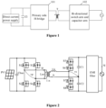
- Figure 1 is a schematic diagram of a micro inverter according to an embodiment of the present disclosure.
- the micro inverter is an isolated inverter, including a transformer for realizing isolation between a primary side and a secondary side.
- the micro inverter includes a primary H-bridge 101, a transformer T, a bi-directional switch arm and a capacitor arm 102.
- the transformer T includes the primary winding, the secondary winding, and an inductor L.
- An input terminal of the primary H-bridge 101 is connected to a direct current power supply.
- the direct current power supply may be a photovoltaic component or a battery.
- the present disclosure is described by taking an example in which the direct current power supply is a photovoltaic component.
- Two output terminals of the primary H-bridge 101 are connected to two terminals on the primary side of the transformer T, respectively.
- Two terminals on the secondary side of the transformer T are connected to an intermediate terminal of the bi-directional switch arm and an intermediate terminal of the capacitor arm, respectively.
- the bi-directional switch arm and the capacitor arm 102 are connected in parallel.
- Figure 2 is a circuit diagram of a micro inverter according to an embodiment of the present disclosure.
- the primary H-bridge includes four switch transistors, i.e., S1, S2, S3 and S4.
- the switch transistor S1 and the switch transistor S2 are connected in series to form a first inverter bridge arm.
- the switch transistor S3 and the switch transistor S4 are connected in series to form a second inverter bridge arm.
- a common terminal shared by the switch transistor S1 and the switch transistor S2 serves as a first output terminal of the primary H-bridge.
- a common terminal shared by the switch transistor S3 and the switch transistor S4 serves as a second output terminal of the primary H-bridge.
- An output voltage of the primary H-bridge is represented as vp
- an output current of the primary H-bridge is represented as ip.
- a turn ratio of the primary winding to the secondary winding of the transformer is 1:n.
- a magnetic inductance of the transformer T is represented as Lm.
- a leakage inductance of the transformer T is represented as Lk.
- An output current of the transformer T is represented as is.
- a voltage on the secondary side of the transformer T is represented as vs.
- An upper half of the bi-directional switch arm includes a fifth switch transistor S5 and a sixth switch transistor S6, which are connected in series.
- a lower half of the bi-directional switch arm includes a seventh switch transistor S7 and an eighth switch transistor S8, which are connected in series.
- the switch transistors on the secondary side operate in a mode 1.
- the S5 and the S7 serve as high-frequency transistors for high-frequency chopping, and the S6 and the S8 are conducted.
- the switch transistors on the secondary side operate in a mode 2.
- the S6 and the S8 serve as high-frequency transistors for high-frequency chopping, and the S5 and the S7 are conducted.
- An upper half of the capacitor arm includes at least one capacitor, and a lower half of the capacitor arm includes at least one capacitor.
- the upper half of the capacitor arm includes a capacitor C1 and the lower half of the capacitor arm includes a capacitor C2.
- the micro inverter can realize a single-stage on-grid function by controlling an external phase-shift angle, which is between the primary H-bridge arm and the secondary arm, and an internal phase-shift angle, which is between the two arms of the primary H-bridge.
- the micro inverter has two degrees of freedom, i.e., D1 for the internal phase-shift angle between the two arms of the primary H-bridge and D2 for the external phase-shift angle between the primary H-bridge arm and the secondary arm.
- Power transmission is realized by controlling the D1 and the D2.
- the D1 is defined to be an angle by which a phase of the S4 lags behind a phase of the S1.
- the D2 is defined to be an angle by which a phase of the S5 (or the S8) lags behind the phase of the S1.
- the output terminal of the micro inverter may further include an EMI filter circuit for filtering out an interference signal, so as to provide a high-quality grid-connected current.
- An output current of the micro inverter, or the grid-connected current, is represented as ig.
- the transformer is in a quantity of one, corresponding to one PV input.
- the PV input may be a photovoltaic component.
- the micro inverter according to another embodiment of the present disclosure may include multiple PV inputs, corresponding to multiple transformers and multiple primary H-bridges, which is described in detail below in conjunction with the drawings.
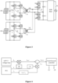
- Figure 3 is a circuit diagram of a micro inverter according to another embodiment of the present disclosure.
- the micro inverter includes N primary H-bridges and N transformers.
- the N transformers share a same bi-directional switch arm and a same capacitor arm.
- N is an integer greater than or equal to 1, which is not limited in the embodiments of the present disclosure. A case in which N is equal to 2 is taken as an example in this embodiment for convenience of description.
- the micro inverter includes two primary H-bridges and two transformers. Connections in the micro inverter may be as shown in Figure 2 and are not repeated here. Output terminals on the secondary sides of the inverter are connected in parallel and share a same bi-directional switch arm and a same capacitor arm.
- the internal phase-shift angle and the external phase-shift angle are controlled, so that capacitance of the capacitor C1 and the capacitor C2 in the secondary arm are required to be large (8uF, for example), in order to ensure that a voltage of the secondary side of the transformer remains unchanged in a switching cycle.
- a reactive current is generated in the capacitor C1 and the capacitor C2 when the grid voltage is applied on the capacitor C1 and the capacitor C2.
- the reactive current has a great impact on the grid-connected current.
- the grid-connected current has a leading phase in a case of no closed loop added. Even if a closed-loop control of a current is added, the reactive current has an adverse impact on the closed-loop control.
- a reactive power compensation solution is provided according to the present disclosure to reduce the impact of the reactive current on the grid-connected current.
- Figure 4 is a schematic diagram showing a control principle of a micro inverter according to an embodiment of the present disclosure.
- the micro inverter includes a controller (not shown in the Figure), a primary H-bridge, a transformer, a bi-directional switch arm and a capacitor arm. Connections in the micro inverter may be with reference to Figure 1 and Figure 2 , which is not described here.
- the controller is configured to: determine a reactive current based on a grid voltage, an equivalent capacitance of an output terminal of the inverter and a grid angle; add the reactive current to a given current i g,ref ; to generate an internal phase-shift angle D1 and an external phase-shift angle D2 from a new given current i g,trans obtained through the addition.
- the internal phase-shift angle D1 refers to a phase-shift angle between the two arms of the primary H-bridge.
- the external phase-shift angle D2 refers to a phase-shift angle between the primary H-bridge and the bi-directional switch arm.
- the given current i g,ref is obtained through maximum power point tracking of the photovoltaic component. As shown in the Figure, am amplitude i m of the given current is obtained through MPPT and a voltage loop. I g,ref represents a cosine value of I m , i.e., a product of I m and sin ⁇ .
- i g,Q represents the reactive current
- V d represents the d-axis component of the grid voltage
- C eq represents the equivalent capacitance of the output terminal of the inverter, i.e., the equivalent capacitance view from the output terminal of the inverter
- ⁇ represents the grid angle
- ⁇ ac represents the angular frequency of grid voltage.
- the d-axis component of the grid voltage and the angular frequency of the grid voltage are obtained through a phase locked loop (PLL).
- PLL phase locked loop
- the input terminal is connected to only one PV device, and therefore the reactive current is added to only the given current for this PV device. That is, the micro inverter includes one primary H-bridge, and the input terminal of the primary H-bridge is configured to connect to a photovoltaic component. The given current is obtained through maximum power point tracking of the photovoltaic component.
- the micro inverter In a case that the micro inverter is connected to multiple PV devices, as shown in Figure 3 , it is necessary to determine operation states of the multiple PV devices. In a case that only one PV device of the multiple PV devices performs power transmission, the reactive current may be added to this PV device. In a case that multiple PV devices perform power transmission, the reactive current may be evenly added to the multiple PV devices, so as to avoid inconsistency in controlling of the multiple PV devices caused by adding all reactive power to a single PV device, thereby reducing the impact of reactive power compensation on control. That is, the micro inverter includes N primary H-bridges and N transformers, and the N transformers share a same bi-directional switch arm and a same capacitor arm. N is an integer greater than or equal to 1. Each primary H-bridge has an input terminal configured to connect to a photovoltaic component. Each photovoltaic component corresponds to a given current obtained through maximum power point tracking of the photovoltaic component.
- the controller is configured to: determine an average reactive current by dividing the reactive current by M, where M is an integer less than or equal to N; and for each photovoltaic component for power transmission: add the average reactive current to a given current corresponding to the photovoltaic component, and generate the internal phase-shift angle and the external phase-shift angle from a new given current obtained through the addition.
- M represents the number of the photovoltaic components for power transmission among the N photovoltaic components, that is, the number of photovoltaic components that are connected to the direct current side of the inverter and used for power transmission.
- a photovoltaic system is further provided according to an embodiment of the present disclosure based on the micro inverter according to the above embodiment.
- the photovoltaic system is described below in conjunction with the drawings.
- Figure 5 is a schematic diagram of a photovoltaic system according to an embodiment of the present disclosure.
- the photovoltaic system includes at least one photovoltaic component and a micro inverter 500 as described in the above embodiment.
- An input terminal of the micro inverter 500 is connected to the photovoltaic component.
- the micro inverter in the photovoltaic system can compensate the reactive current generated by the capacitor at the output terminal of the micro inverter. Therefore, with the photovoltaic system, the impact of the reactive current on the grid can be reduced, and thereby the quality of the grid-connected current is improved.
- a method for controlling a micro inverter is further provided according to an embodiment of the present disclosure, which is described in detail below in conjunction with the drawings.
- FIG. 5 is a flowchart of a method for controlling a micro inverter according to an embodiment of the present disclosure.
- the method for controlling a micro inverter according to this embodiment is applied to the micro inverter as described in the above embodiments.
- the micro inverter includes a primary H-bridge, a transformer, a bi-directional switch arm and a capacitor arm.
- An input terminal of the primary H-bridge is connected to a direct current power supply.
- Two output terminals of the primary H-bridge are connected to two terminals on the primary side of the transformer, respectively.
- Two terminals on the secondary side of the transformer are connected to an intermediate terminal of the bi-directional switch arm and an intermediate terminal of the capacitor arm, respectively.
- the bi-directional switch arm and the capacitor arm are connected in parallel.
- the method includes the following steps S501 to S503.
- step S501 a reactive current is determined based on a grid voltage, an equivalent capacitance of an output terminal of the inverter and a grid angle.
- a process of determining the reactive current based on the grid voltage, the equivalent capacitance of the output terminal of the inverter and the grid angle includes: determining the reactive current based on a d-axis component of the grid voltage, an angular frequency of the grid voltage, the equivalent capacitance of the output terminal of the inverter, and a cosine value of the grid angle.
- the d-axis component of the grid voltage and the angular frequency of the grid voltage are obtained through a phase locked loop.
- step S502 the reactive current is added to a given current.
- a process of adding the reactive current to the given current to generate an internal phase-shift angle and an external phase-shift angle from a new given current obtained through the addition includes: determining an average reactive current by dividing the reactive current by M, where M is an integer less than or equal to N; and for each photovoltaic component for power transmission, adding the average reactive current to a given current corresponding to the photovoltaic component, and generating the internal phase-shift angle and the external phase-shift angle from a new given current obtained through the addition.
- M represents the number of photovoltaic components for power transmission among the N photovoltaic components.
- an internal phase-shift angle and an external phase-shift angle are generated from a new given current obtained through the addition of the reactive current and the given current.
- the internal phase-shift angle refers to a phase-shift angle between the two arms of the primary H-bridge.
- the external phase-shift angle refers to a phase-shift angle between the primary H-bridge and the bi-directional switch arm.
- an input terminal of the primary H-bridge is configured to connect to a photovoltaic component.
- the given current is obtained through maximum power point tracking of the photovoltaic component.
- the N transformers share a same bi-directional switch arm and a same capacitor arm.
- N is an integer greater than or equal to 1.
- Each primary H-bridge has an input terminal configured to connect to a photovoltaic component.
- Each photovoltaic component corresponds to a given current obtained through maximum power point tracking of the photovoltaic component.
- the reactive current generated due to the equivalent capacitor at the output terminal of the inverter has an impact on a quality of a grid-connected current. Therefore, the reactive current is compensated in the present disclosure.
- the reactive current is determined based on the grid voltage, the equivalent capacitance of the output terminal of the inverter and the grid angle.
- the reactive current is added to the given current to generate the internal phase-shift angle and the external phase-shift angle from the new given current obtained through the addition. In this way, the impact of the reactive current on the grid-connected current is reduced.
- the reactive current is added to the given current in feedforward control in advance, so that the quality of the grid-connected current is improved.
Landscapes
- Engineering & Computer Science (AREA)
- Power Engineering (AREA)
- Inverter Devices (AREA)
- Control Of Electrical Variables (AREA)
Abstract
Description
- The present disclosure relates to the technical field of photovoltaic power generation, and in particular to a micro inverter, a photovoltaic system and a method for controlling the micro inverter.
- Photovoltaic power generation develops and is increasingly applied to households. With the development of household photovoltaic systems, a household inverter has smaller size, and micro inverters are provided.
- However, due to a capacitor at an output terminal of the micro inverter, a reactive current is generated when a grid voltage is applied on the capacitor. The reactive current has a great impact on a grid current.
- In view of this, a micro inverter, a photovoltaic system and a method for controlling the micro inverter are provided according to the present disclosure, in order to reduce an impact of a reactive current on a grid current.
- A micro inverter is provided according to the present disclosure. The micro inverter includes a controller, a primary H-bridge, a transformer, a bi-directional switch arm, and a capacitor arm. An input terminal of the primary H-bridge is connected to a direct current power supply. Two output terminals of the primary H-bridge are connected to two terminals of a primary side of the transformer, respectively. Two terminals on a secondary side of the transformer are connected to an intermediate terminal of the bi-directional switch arm and an intermediate terminal of the capacitor arm, respectively. The bi-directional switch arm and the capacitor arm are connected in parallel. The controller is configured to: determine a reactive current based on a grid voltage, an equivalent capacitance of an output terminal of the inverter and a grid angle; add the reactive current to a given current to generate an internal phase-shift angle and an external phase-shift angle from a new given current obtained through the addition, where the internal phase-shift angle refers to a phase-shift angle between two arms of the primary H-bridge and the external phase-shift angle refers to a phase-shift angle between the primary H-bridge and the bi-directional switch arm.
- Preferably, the primary H-bridge is in a quantity of one. The input terminal of the primary H-bridge is configured to connect to a photovoltaic component. The given current is obtained through maximum power point tracking of the photovoltaic component.
- Preferably, the primary H-bridge is in a quantity of N and the transformer is in a quantity of N, where N is an integer greater than or equal to 1. The N transformers share the bi-directional switch arm and the capacitor arm. Each primary H-bridge has an input terminal configured to connect to a corresponding photovoltaic component. Each photovoltaic component corresponds to a given current obtained through maximum power point tracking of the photovoltaic component. The controller is configured to determine an average reactive current by dividing the reactive current by M, where M is an integer less than or equal to N; and for each photovoltaic component for power transmission, add the average reactive current to a given current corresponding to the photovoltaic component, and generate the internal phase-shift angle and the external phase-shift angle from a new given current obtained through the addition.
- Preferably, the controller is configured to determine the reactive current based on a d-axis component of the grid voltage, an angular frequency of the grid voltage, the equivalent capacitance of the output terminal of the inverter, and a cosine value of the grid angle.
- Preferably, the d-axis component of the grid voltage and the angular frequency of the grid voltage are obtained through a phase locked loop.
- Preferably, the transformer includes a primary winding and a secondary winding. An upper half of the bi-directional switch arm includes a first switch transistor and a second switch transistor connected in series, and a lower half of the bi-directional switch arm includes a third switch transistor and a fourth switch transistor connected in series. An upper half of the capacitor arm includes at least one capacitor, and a lower half of the capacitor arm includes at least one capacitor.
- A photovoltaic system is further provided according to the present disclosure. The photovoltaic system includes the micro inverter described above and at least one photovoltaic component. An input terminal of the micro inverter is connected to the photovoltaic component.
- A method for controlling a micro inverter is further provided according to the present disclosure. The micro inverter includes a primary H-bridge, a transformer, a bi-directional switch arm and a capacitor arm. An input terminal of the primary H-bridge is connected to a direct current power supply. Two output terminals of the primary H-bridge are connected to two terminals of a primary side of the transformer, respectively; and two terminals on a secondary side of the transformer are connected to an intermediate terminal of the bi-directional switch arm and an intermediate terminal of the capacitor arm, respectively. The bi-directional switch arm and the capacitor arm are connected in parallel. The method includes: determining a reactive current based on a grid voltage, an equivalent capacitance of an output terminal of the inverter and a grid angle; and adding the reactive current to a given current to generate an internal phase-shift angle and an external phase-shift angle from a new given current obtained through the addition, wherein the internal phase-shift angle refers to a phase-shift angle between two arms of the primary H-bridge and the external phase-shift angle refers to a phase-shift angle between the primary H-bridge and the bi-directional switch arm.
- Preferably, the primary H-bridge is in a quantity of one. The input terminal of the primary H-bridge is configured to connect to a photovoltaic component. The given current is obtained through maximum power point tracking of the photovoltaic component.
- Preferably, the primary H-bridge is in a quantity of N and the transformer is in a quantity of N, where N is an integer greater than or equal to 1. The N transformers share the bi-directional switch arm and the capacitor arm. Each primary H-bridge has an input terminal configured to connect to a corresponding photovoltaic component. Each photovoltaic component corresponds to a given current obtained through maximum power point tracking of the photovoltaic component. The adding the reactive current to a given current to generate an internal phase-shift angle and an external phase-shift angle from a new given current obtained through the addition includes: determining an average reactive current by dividing the reactive current by M, where M is an integer less than or equal to N; and for each photovoltaic component for power transmission, adding the average reactive current to a given current corresponding to the photovoltaic component, and generating the internal phase-shift angle and the external phase-shift angle from a new given current obtained through the addition.
- Preferably, the determining a reactive current based on a grid voltage, an equivalent capacitance of an output terminal of the inverter and a grid angle includes: determining the reactive current based on a d-axis component of the grid voltage, an angular frequency of the grid voltage, the equivalent capacitance of the output terminal of the inverter, and a cosine value of the grid angle.
- Preferably, the d-axis component of the grid voltage and the angular frequency of the grid voltage are obtained through a phase locked loop.
- It can be seen that the present disclosure has the following beneficial effects.
- In the micro inverter according to the present disclosure, it is considered that the reactive current generated due to the equivalent capacitor at the output terminal of the inverter has an impact on a quality of a grid-connected current. Therefore, the reactive current is compensated in the present disclosure. The reactive current is determined based on the grid voltage, the equivalent capacitance of the output terminal of the inverter and the grid angle. The reactive current is added to the given current to generate the internal phase-shift angle and the external phase-shift angle from the new given current obtained through the addition. In this way, the impact of the reactive current on the grid-connected current is reduced. The reactive current is added to the given current in feedforward control in advance, so that the quality of the grid-connected current is improved.
-
-
Figure 1 is a schematic diagram of a micro inverter according to an embodiment of the present disclosure; -
Figure 2 is a circuit diagram of a micro inverter according to an embodiment of the present disclosure; -
Figure 3 is a circuit diagram of a micro inverter according to another embodiment of the present disclosure; -
Figure 4 is a schematic diagram showing a control principle of a micro inverter according to an embodiment of the present disclosure; and -
Figure 5 is a flow chart of a method for controlling a micro inverter according to an embodiment of the present disclosure. - In order to enable those skilled in the art to better understand the technical solutions according to the embodiments of the present disclosure, a micro inverter is first described below by taking an example in which the micro inverter is applied to a household photovoltaic system.
- Reference is made to
Figure 1 , which is a schematic diagram of a micro inverter according to an embodiment of the present disclosure. - The micro inverter is an isolated inverter, including a transformer for realizing isolation between a primary side and a secondary side. The micro inverter includes a primary H-
bridge 101, a transformer T, a bi-directional switch arm and acapacitor arm 102. The transformer T includes the primary winding, the secondary winding, and an inductor L. - An input terminal of the primary H-
bridge 101 is connected to a direct current power supply. The direct current power supply may be a photovoltaic component or a battery. The present disclosure is described by taking an example in which the direct current power supply is a photovoltaic component. Two output terminals of the primary H-bridge 101 are connected to two terminals on the primary side of the transformer T, respectively. Two terminals on the secondary side of the transformer T are connected to an intermediate terminal of the bi-directional switch arm and an intermediate terminal of the capacitor arm, respectively. The bi-directional switch arm and thecapacitor arm 102 are connected in parallel. - Reference is made to
Figure 2 , which is a circuit diagram of a micro inverter according to an embodiment of the present disclosure. - As shown in
Figure 2 , the primary H-bridge includes four switch transistors, i.e., S1, S2, S3 and S4. The switch transistor S1 and the switch transistor S2 are connected in series to form a first inverter bridge arm. The switch transistor S3 and the switch transistor S4 are connected in series to form a second inverter bridge arm. A common terminal shared by the switch transistor S1 and the switch transistor S2 serves as a first output terminal of the primary H-bridge. A common terminal shared by the switch transistor S3 and the switch transistor S4 serves as a second output terminal of the primary H-bridge. An output voltage of the primary H-bridge is represented as vp, and an output current of the primary H-bridge is represented as ip. A turn ratio of the primary winding to the secondary winding of the transformer is 1:n. A magnetic inductance of the transformer T is represented as Lm. A leakage inductance of the transformer T is represented as Lk. An output current of the transformer T is represented as is. A voltage on the secondary side of the transformer T is represented as vs. - An upper half of the bi-directional switch arm includes a fifth switch transistor S5 and a sixth switch transistor S6, which are connected in series. A lower half of the bi-directional switch arm includes a seventh switch transistor S7 and an eighth switch transistor S8, which are connected in series. In a case that the grid voltage is greater than zero, the switch transistors on the secondary side operate in a
mode 1. In themode 1, the S5 and the S7 serve as high-frequency transistors for high-frequency chopping, and the S6 and the S8 are conducted. In a case that the grid voltage is less than zero, the switch transistors on the secondary side operate in amode 2. In themode 2, the S6 and the S8 serve as high-frequency transistors for high-frequency chopping, and the S5 and the S7 are conducted. - An upper half of the capacitor arm includes at least one capacitor, and a lower half of the capacitor arm includes at least one capacitor. In an embodiment, the upper half of the capacitor arm includes a capacitor C1 and the lower half of the capacitor arm includes a capacitor C2.
- The micro inverter can realize a single-stage on-grid function by controlling an external phase-shift angle, which is between the primary H-bridge arm and the secondary arm, and an internal phase-shift angle, which is between the two arms of the primary H-bridge. The micro inverter has two degrees of freedom, i.e., D1 for the internal phase-shift angle between the two arms of the primary H-bridge and D2 for the external phase-shift angle between the primary H-bridge arm and the secondary arm. Power transmission is realized by controlling the D1 and the D2. The D1 is defined to be an angle by which a phase of the S4 lags behind a phase of the S1. The D2 is defined to be an angle by which a phase of the S5 (or the S8) lags behind the phase of the S1.
- In addition, the output terminal of the micro inverter may further include an EMI filter circuit for filtering out an interference signal, so as to provide a high-quality grid-connected current. An output current of the micro inverter, or the grid-connected current, is represented as ig.
- In the micro inverter as shown in
Figure 2 , the transformer is in a quantity of one, corresponding to one PV input. It should be understood that the PV input may be a photovoltaic component. The micro inverter according to another embodiment of the present disclosure may include multiple PV inputs, corresponding to multiple transformers and multiple primary H-bridges, which is described in detail below in conjunction with the drawings. - Reference is made to
Figure 3 , which is a circuit diagram of a micro inverter according to another embodiment of the present disclosure. - In this embodiment, the micro inverter includes N primary H-bridges and N transformers. The N transformers share a same bi-directional switch arm and a same capacitor arm. N is an integer greater than or equal to 1, which is not limited in the embodiments of the present disclosure. A case in which N is equal to 2 is taken as an example in this embodiment for convenience of description.
- As shown in
Figure 3 , the micro inverter includes two primary H-bridges and two transformers. Connections in the micro inverter may be as shown inFigure 2 and are not repeated here. Output terminals on the secondary sides of the inverter are connected in parallel and share a same bi-directional switch arm and a same capacitor arm. - The internal phase-shift angle and the external phase-shift angle are controlled, so that capacitance of the capacitor C1 and the capacitor C2 in the secondary arm are required to be large (8uF, for example), in order to ensure that a voltage of the secondary side of the transformer remains unchanged in a switching cycle. A reactive current is generated in the capacitor C1 and the capacitor C2 when the grid voltage is applied on the capacitor C1 and the capacitor C2.
- The reactive current has a great impact on the grid-connected current. The grid-connected current has a leading phase in a case of no closed loop added. Even if a closed-loop control of a current is added, the reactive current has an adverse impact on the closed-loop control.
- To solve the above problem, a reactive power compensation solution is provided according to the present disclosure to reduce the impact of the reactive current on the grid-connected current.
- In order to make the above objectives, features and advantages of the present disclosure more obvious and easier to be understood, the embodiments of the present disclosure are described in detail below in conjunction with the drawings and embodiments.
- Reference is made to
Figure 4 , which is a schematic diagram showing a control principle of a micro inverter according to an embodiment of the present disclosure. - The micro inverter according to this embodiment includes a controller (not shown in the Figure), a primary H-bridge, a transformer, a bi-directional switch arm and a capacitor arm. Connections in the micro inverter may be with reference to
Figure 1 and Figure 2 , which is not described here. - The controller is configured to: determine a reactive current based on a grid voltage, an equivalent capacitance of an output terminal of the inverter and a grid angle; add the reactive current to a given current ig,ref; to generate an internal phase-shift angle D1 and an external phase-shift angle D2 from a new given current ig,trans obtained through the addition. The internal phase-shift angle D1 refers to a phase-shift angle between the two arms of the primary H-bridge. The external phase-shift angle D2 refers to a phase-shift angle between the primary H-bridge and the bi-directional switch arm.
- The given current ig,ref is obtained through maximum power point tracking of the photovoltaic component. As shown in the Figure, am amplitude im of the given current is obtained through MPPT and a voltage loop. Ig,ref represents a cosine value of Im, i.e., a product of Im and sinθ.
- The controller is specifically configured to determine the reactive current based on a d-axis component of the grid voltage, an angular frequency of the grid voltage, the equivalent capacitance of the output terminal of the inverter, and the cosine value of the grid angle according to the following equation:

- In the above equation, ig,Q represents the reactive current; Vd represents the d-axis component of the grid voltage; Ceq represents the equivalent capacitance of the output terminal of the inverter, i.e., the equivalent capacitance view from the output terminal of the inverter; θ represents the grid angle; and ωac represents the angular frequency of grid voltage.
- The d-axis component of the grid voltage and the angular frequency of the grid voltage are obtained through a phase locked loop (PLL).
- In the micro inverter as shown in
Figure 2 , the input terminal is connected to only one PV device, and therefore the reactive current is added to only the given current for this PV device. That is, the micro inverter includes one primary H-bridge, and the input terminal of the primary H-bridge is configured to connect to a photovoltaic component. The given current is obtained through maximum power point tracking of the photovoltaic component. - In a case that the micro inverter is connected to multiple PV devices, as shown in
Figure 3 , it is necessary to determine operation states of the multiple PV devices. In a case that only one PV device of the multiple PV devices performs power transmission, the reactive current may be added to this PV device. In a case that multiple PV devices perform power transmission, the reactive current may be evenly added to the multiple PV devices, so as to avoid inconsistency in controlling of the multiple PV devices caused by adding all reactive power to a single PV device, thereby reducing the impact of reactive power compensation on control. That is, the micro inverter includes N primary H-bridges and N transformers, and the N transformers share a same bi-directional switch arm and a same capacitor arm. N is an integer greater than or equal to 1. Each primary H-bridge has an input terminal configured to connect to a photovoltaic component. Each photovoltaic component corresponds to a given current obtained through maximum power point tracking of the photovoltaic component. - The controller is configured to: determine an average reactive current by dividing the reactive current by M, where M is an integer less than or equal to N; and for each photovoltaic component for power transmission: add the average reactive current to a given current corresponding to the photovoltaic component, and generate the internal phase-shift angle and the external phase-shift angle from a new given current obtained through the addition. M represents the number of the photovoltaic components for power transmission among the N photovoltaic components, that is, the number of photovoltaic components that are connected to the direct current side of the inverter and used for power transmission.
- A photovoltaic system is further provided according to an embodiment of the present disclosure based on the micro inverter according to the above embodiment. The photovoltaic system is described below in conjunction with the drawings.
- Reference is made to
Figure 5 , which is a schematic diagram of a photovoltaic system according to an embodiment of the present disclosure. - In an embodiment, the photovoltaic system includes at least one photovoltaic component and a micro inverter 500 as described in the above embodiment. An input terminal of the micro inverter 500 is connected to the photovoltaic component.
- The micro inverter in the photovoltaic system according to the embodiment of the present disclosure can compensate the reactive current generated by the capacitor at the output terminal of the micro inverter. Therefore, with the photovoltaic system, the impact of the reactive current on the grid can be reduced, and thereby the quality of the grid-connected current is improved.
- Based on the micro inverter and the photovoltaic system according to the above embodiments, a method for controlling a micro inverter is further provided according to an embodiment of the present disclosure, which is described in detail below in conjunction with the drawings.
- Reference is made to
Figure 5 , which is a flowchart of a method for controlling a micro inverter according to an embodiment of the present disclosure. - The method for controlling a micro inverter according to this embodiment is applied to the micro inverter as described in the above embodiments. The micro inverter includes a primary H-bridge, a transformer, a bi-directional switch arm and a capacitor arm. An input terminal of the primary H-bridge is connected to a direct current power supply. Two output terminals of the primary H-bridge are connected to two terminals on the primary side of the transformer, respectively. Two terminals on the secondary side of the transformer are connected to an intermediate terminal of the bi-directional switch arm and an intermediate terminal of the capacitor arm, respectively. The bi-directional switch arm and the capacitor arm are connected in parallel.
- The method includes the following steps S501 to S503.
- In step S501, a reactive current is determined based on a grid voltage, an equivalent capacitance of an output terminal of the inverter and a grid angle.
- A process of determining the reactive current based on the grid voltage, the equivalent capacitance of the output terminal of the inverter and the grid angle includes: determining the reactive current based on a d-axis component of the grid voltage, an angular frequency of the grid voltage, the equivalent capacitance of the output terminal of the inverter, and a cosine value of the grid angle.
- The d-axis component of the grid voltage and the angular frequency of the grid voltage are obtained through a phase locked loop.
- In step S502, the reactive current is added to a given current.
- A process of adding the reactive current to the given current to generate an internal phase-shift angle and an external phase-shift angle from a new given current obtained through the addition includes: determining an average reactive current by dividing the reactive current by M, where M is an integer less than or equal to N; and for each photovoltaic component for power transmission, adding the average reactive current to a given current corresponding to the photovoltaic component, and generating the internal phase-shift angle and the external phase-shift angle from a new given current obtained through the addition. M represents the number of photovoltaic components for power transmission among the N photovoltaic components.
- In step S503, an internal phase-shift angle and an external phase-shift angle are generated from a new given current obtained through the addition of the reactive current and the given current. The internal phase-shift angle refers to a phase-shift angle between the two arms of the primary H-bridge. The external phase-shift angle refers to a phase-shift angle between the primary H-bridge and the bi-directional switch arm.
- In a case that the primary H-bridge included in the micro inverter is in a quantity of one, an input terminal of the primary H-bridge is configured to connect to a photovoltaic component. The given current is obtained through maximum power point tracking of the photovoltaic component.
- In a case that the primary H-bridge included in the micro inverter is in a quantity of N and the transformer included in the micro inverter is in a quantity of M, the N transformers share a same bi-directional switch arm and a same capacitor arm. N is an integer greater than or equal to 1. Each primary H-bridge has an input terminal configured to connect to a photovoltaic component. Each photovoltaic component corresponds to a given current obtained through maximum power point tracking of the photovoltaic component.
- With the method for controlling a micro inverter according to the present disclosure, it is considered that the reactive current generated due to the equivalent capacitor at the output terminal of the inverter has an impact on a quality of a grid-connected current. Therefore, the reactive current is compensated in the present disclosure. The reactive current is determined based on the grid voltage, the equivalent capacitance of the output terminal of the inverter and the grid angle. The reactive current is added to the given current to generate the internal phase-shift angle and the external phase-shift angle from the new given current obtained through the addition. In this way, the impact of the reactive current on the grid-connected current is reduced. The reactive current is added to the given current in feedforward control in advance, so that the quality of the grid-connected current is improved.
- With the above description of the disclosed embodiments, those skilled in the art can implement or use the present disclosure. It is obvious for those skilled in the art to make many modifications to these embodiments. The general principle defined herein may be applied to other embodiments without departing from the spirit or scope of the present disclosure. Therefore, the present disclosure should not be limited to the embodiments described herein but have the widest scope that complies with the principle and novelty disclosed in the present disclosure.
Claims (12)
- A micro inverter, comprising a controller, a primary H-bridge, a transformer, a bi-directional switch arm, and a capacitor arm, whereinan input terminal of the primary H-bridge is connected to a direct current power supply;two output terminals of the primary H-bridge are connected to two terminals on a primary side of the transformer, respectively;two terminals on a secondary side of the transformer are connected to an intermediate terminal of the bi-directional switch arm and an intermediate terminal of the capacitor arm, respectively;the bi-directional switch arm and the capacitor arm are connected in parallel; andthe controller is configured to:determine a reactive current based on a grid voltage, an equivalent capacitance of an output terminal of the inverter and a grid angle;add the reactive current to a given current to generate an internal phase-shift angle and an external phase-shift angle from a new given current obtained through the addition, wherein the internal phase-shift angle refers to a phase-shift angle between two arms of the primary H-bridge and the external phase-shift angle refers to a phase-shift angle between the primary H-bridge and the bi-directional switch arm.
- The micro inverter according to claim 1, wherein:the primary H-bridge is in a quantity of one;the input terminal of the primary H-bridge is configured to connect to a photovoltaic component; andthe given current is obtained through maximum power point tracking of the photovoltaic component.
- The micro inverter according to claim 1, wherein:the primary H-bridge is in a quantity of N and the transformer is in a quantity of N, where N is an integer greater than or equal to 1,the N transformers share the bi-directional switch arm and the capacitor arm, andeach primary H-bridge has an input terminal configured to connect to a corresponding photovoltaic component,each photovoltaic component corresponds to a given current obtained through maximum power point tracking of the photovoltaic component; andthe controller is configured todetermine an average reactive current by dividing the reactive current by M, where M is an integer less than or equal to N; andfor each photovoltaic component for power transmission, add the average reactive current to a given current corresponding to the photovoltaic component, and generate the internal phase-shift angle and the external phase-shift angle from a new given current obtained through the addition.
- The micro inverter according to any one of claims 1 to 3, wherein the controller is configured to: determine the reactive current based on a d-axis component of the grid voltage, an angular frequency of the grid voltage, the equivalent capacitance of the output terminal of the inverter, and a cosine value of the grid angle.
- The micro inverter according to any one of claims 1 to 3, wherein the d-axis component of the grid voltage and the angular frequency of the grid voltage are obtained through a phase locked loop.
- The micro inverter according to any one of claims 1 to 3, wherein:the transformer comprises a primary winding and a secondary winding;an upper half of the bi-directional switch arm comprises a first switch transistor and a second switch transistor connected in series, and a lower half of the bi-directional switch arm comprises a third switch transistor and a fourth switch transistor connected in series; andan upper half of the capacitor arm comprises at least one capacitor, and a lower half of the capacitor arm comprises at least one capacitor.
- A photovoltaic system, comprising:the micro inverter according to any one of claims 1 to 6; andat least one photovoltaic component, wherein
an input terminal of the micro inverter is connected to the photovoltaic component. - A method for controlling a micro inverter, wherein:the micro inverter comprises a primary H-bridge, a transformer, a bi-directional switch arm and a capacitor arm, an input terminal of the primary H-bridge is connected to a direct current power supply; two output terminals of the primary H-bridge are connected to two terminals on a primary side of the transformer, respectively; two terminals on a secondary side of the transformer are connected to an intermediate terminal of the bi-directional switch arm and an intermediate terminal of the capacitor arm, respectively; and the bi-directional switch arm and the capacitor arm are connected in parallel; andthe method comprises:determining a reactive current based on a grid voltage, an equivalent capacitance of an output terminal of the inverter and a grid angle; andadding the reactive current to a given current to generate an internal phase-shift angle and an external phase-shift angle from a new given current obtained through the addition, wherein the internal phase-shift angle refers to a phase-shift angle between two arms of the primary H-bridge and the external phase-shift angle refers to a phase-shift angle between the primary H-bridge and the bi-directional switch arm.
- The method according to claim 8, wherein:the primary H-bridge is in a quantity of one;the input terminal of the primary H-bridge is configured to connect to a photovoltaic component; andthe given current is obtained through maximum power point tracking of the photovoltaic component.
- The method according to claim 8, whereinthe primary H-bridge is in a quantity of N and the transformer is in a quantity of N, where N is an integer greater than or equal to 1,the N transformers share the bi-directional switch arm and the capacitor arm, andeach primary H-bridge has an input terminal configured to connect to a corresponding photovoltaic component,each photovoltaic component corresponds to a given current obtained through maximum power point tracking of the photovoltaic component; andthe adding the reactive current to a given current to generate an internal phase-shift angle and an external phase-shift angle from a new given current obtained through the addition comprises:determining an average reactive current by dividing the reactive current by M, where M is an integer less than or equal to N; andfor each photovoltaic component for power transmission, adding the average reactive current to a given current corresponding to the photovoltaic component and generating the internal phase-shift angle and the external phase-shift angle from a new given current obtained through the addition.
- The method according to any one of claims 8 to 10, wherein the determining a reactive current based on a grid voltage, an equivalent capacitance of an output terminal of the inverter and a grid angle comprises:
determining the reactive current based on a d-axis component of the grid voltage, an angular frequency of the grid voltage, the equivalent capacitance of the output terminal of the inverter, and a cosine value of the grid angle. - The method according to any one of claims 8 to 10, wherein the d-axis component of the grid voltage and the angular frequency of the grid voltage are obtained through a phase locked loop.
Applications Claiming Priority (1)
| Application Number | Priority Date | Filing Date | Title |
|---|---|---|---|
| CN202211441143.7A CN115694237A (en) | 2022-11-17 | 2022-11-17 | A kind of micro inverter, photovoltaic system and control method |
Publications (1)
| Publication Number | Publication Date |
|---|---|
| EP4372974A1 true EP4372974A1 (en) | 2024-05-22 |
Family
ID=85053370
Family Applications (1)
| Application Number | Title | Priority Date | Filing Date |
|---|---|---|---|
| EP23207931.9A Pending EP4372974A1 (en) | 2022-11-17 | 2023-11-06 | Micro inverter, photovoltaic system and control method |
Country Status (4)
| Country | Link |
|---|---|
| US (1) | US12476549B2 (en) |
| EP (1) | EP4372974A1 (en) |
| CN (1) | CN115694237A (en) |
| AU (1) | AU2023258431B2 (en) |
Families Citing this family (4)
| Publication number | Priority date | Publication date | Assignee | Title |
|---|---|---|---|---|
| CN117977995B (en) * | 2023-05-12 | 2024-12-17 | 上海交通大学 | Multi-port light storage complementary power supply system and control method and control system thereof |
| CN117613995A (en) * | 2023-10-20 | 2024-02-27 | 浙江艾罗网络能源技术股份有限公司 | Microinverter control method and related equipment |
| CN118367629B (en) * | 2024-06-20 | 2024-09-06 | 宁波公牛新能源科技有限公司 | Reactive power control method and device, controller and storage medium of photovoltaic inverter |
| CN121689863A (en) * | 2024-09-02 | 2026-03-17 | 华为数字能源技术有限公司 | Inverter and output current control method for inverter |
Citations (1)
| Publication number | Priority date | Publication date | Assignee | Title |
|---|---|---|---|---|
| WO2021252911A1 (en) * | 2020-06-12 | 2021-12-16 | Board Of Regents, The University Of Texas System | Highly efficient isolated bidirectional dc/ac topologies |
Family Cites Families (19)
| Publication number | Priority date | Publication date | Assignee | Title |
|---|---|---|---|---|
| US7796406B2 (en) * | 2007-07-31 | 2010-09-14 | Lumenis Ltd. | Apparatus and method for high efficiency isolated power converter |
| WO2013163780A1 (en) * | 2012-05-02 | 2013-11-07 | 上海康威特吉能源技术有限公司 | Alternately parallel-connected grid-connected inverter and control method therefor |
| US9130470B2 (en) * | 2012-09-14 | 2015-09-08 | General Electric Company | Power converter control system and method with separate primary and secondary controllers |
| WO2014103105A1 (en) * | 2012-12-28 | 2014-07-03 | パナソニック株式会社 | Dc-to-dc converter |
| US11211897B2 (en) * | 2017-11-15 | 2021-12-28 | Lg Electronics Inc. | Photovoltaic module |
| CN108011396A (en) * | 2017-12-13 | 2018-05-08 | 阳光电源股份有限公司 | A kind of capacitive reactive power compensation method and system |
| KR102688640B1 (en) * | 2018-11-26 | 2024-07-24 | 엘지전자 주식회사 | Photovoltaic module |
| DE102019211968A1 (en) * | 2019-08-09 | 2021-02-11 | Robert Bosch Gmbh | Control method for a DC voltage converter and DC voltage converter |
| JP7190664B2 (en) * | 2019-09-18 | 2022-12-16 | パナソニックIpマネジメント株式会社 | power converter |
| US11594973B2 (en) * | 2020-08-04 | 2023-02-28 | Delta Electronics Inc. | Multiple-port bidirectional converter and control method thereof |
| CN112737350B (en) * | 2021-03-29 | 2021-06-25 | 昱能科技股份有限公司 | Phase-shifted full-bridge converter and control method, device and medium thereof |
| CN112953245B (en) * | 2021-04-23 | 2023-09-15 | 中南大学 | Soft switching control method for full load range of dual active bridge converter |
| CN113258817B (en) * | 2021-06-24 | 2021-12-28 | 国创移动能源创新中心(江苏)有限公司 | Single-stage isolated bidirectional converter and control method thereof |
| CN116247937A (en) * | 2021-12-07 | 2023-06-09 | 台达电子企业管理(上海)有限公司 | A resonant converter and a method for controlling the resonant converter |
| CN114553043A (en) * | 2022-03-04 | 2022-05-27 | 阳光电源股份有限公司 | Micro inverter |
| CN115021570B (en) * | 2022-05-26 | 2023-04-18 | 上海交通大学 | Circuit modeling method and output current control method of double-active bridge type micro-inverter |
| CN114977872B (en) * | 2022-05-26 | 2023-05-12 | 上海交通大学 | Bidirectional double-active-bridge micro-inverter and power modulation mode switching method and system |
| JP2025021689A (en) * | 2023-08-01 | 2025-02-14 | 矢崎総業株式会社 | Charger, control method and control program thereof |
| US20250047188A1 (en) * | 2023-08-02 | 2025-02-06 | Virginia Tech Intellectual Properties, Inc. | Resonant commutation and quasi-trapezoidal current control in electronic transformers |
-
2022
- 2022-11-17 CN CN202211441143.7A patent/CN115694237A/en active Pending
-
2023
- 2023-11-02 US US18/500,885 patent/US12476549B2/en active Active
- 2023-11-03 AU AU2023258431A patent/AU2023258431B2/en active Active
- 2023-11-06 EP EP23207931.9A patent/EP4372974A1/en active Pending
Patent Citations (1)
| Publication number | Priority date | Publication date | Assignee | Title |
|---|---|---|---|---|
| WO2021252911A1 (en) * | 2020-06-12 | 2021-12-16 | Board Of Regents, The University Of Texas System | Highly efficient isolated bidirectional dc/ac topologies |
Non-Patent Citations (3)
| Title |
|---|
| BHATTACHARJEE AMIT ET AL: "An Interleaved Boost and Dual Active Bridge Based Three Port Microinverter", 2020 IEEE APPLIED POWER ELECTRONICS CONFERENCE AND EXPOSITION (APEC), IEEE, 15 March 2020 (2020-03-15), pages 1320 - 1326, XP033785032, DOI: 10.1109/APEC39645.2020.9124515 * |
| KWON OWON ET AL: "Highly Efficient Single-Stage DAB Microinverter Using a Novel Modulation Strategy to Minimize Reactive Power", IEEE JOURNAL OF EMERGING AND SELECTED TOPICS IN POWER ELECTRONICS, IEEE, PISCATAWAY, NJ, USA, vol. 10, no. 1, 17 June 2021 (2021-06-17), pages 544 - 552, XP011899378, ISSN: 2168-6777, [retrieved on 20220201], DOI: 10.1109/JESTPE.2021.3090097 * |
| SAYED MAHMOUD A ET AL: "Advanced PWM Switching Technique for Accurate Unity Power Factor of Bidirectional Three-Phase Grid-Tied DC-AC Converters", IEEE TRANSACTIONS ON INDUSTRY APPLICATIONS, IEEE SERVICE CENTER, PISCATAWAY, NJ, US, vol. 55, no. 6, 1 November 2019 (2019-11-01), pages 7614 - 7627, XP011755041, ISSN: 0093-9994, [retrieved on 20191111], DOI: 10.1109/TIA.2019.2919596 * |
Also Published As
| Publication number | Publication date |
|---|---|
| CN115694237A (en) | 2023-02-03 |
| US20240170965A1 (en) | 2024-05-23 |
| AU2023258431B2 (en) | 2025-02-13 |
| AU2023258431A1 (en) | 2024-06-06 |
| US12476549B2 (en) | 2025-11-18 |
Similar Documents
| Publication | Publication Date | Title |
|---|---|---|
| EP4372974A1 (en) | Micro inverter, photovoltaic system and control method | |
| EP3550692A1 (en) | Medium and high voltage energy conversion system | |
| US12438372B2 (en) | Island microgrid system, and interactive oscillation suppression method and system therefor | |
| CN104811067B (en) | PR (proportional resonant) controller-based NMC-HVDC (modular multilevel converter-high voltage direct current) circulating current suppression method | |
| CN113346785B (en) | Adaptive error compensation control system and method for inverter | |
| Darwish et al. | Current-source single-phase module integrated inverters for PV grid-connected applications | |
| AU2023387478B2 (en) | Microinverter, photovoltaic system, and control method | |
| EP4618348A1 (en) | Converter and zero crossing point control method therefor | |
| CN117713134A (en) | Low-voltage ride-through frequency supporting method for photovoltaic inverter in weak current network state | |
| CN108400737A (en) | Dead-zone compensation method, circuit, power electronic equipment and computer storage media | |
| CN112953254A (en) | Three-phase power electronic transformer topology and control method thereof | |
| CN117914170A (en) | Converter midpoint voltage control method and system based on multi-resonance and virtual impedance | |
| He et al. | Switching-cycle-based startup for grid-tied inverters | |
| CN116317654A (en) | Multilevel inverter, power system and DC bus voltage balancing method | |
| CN112087158A (en) | Open-loop circulating current restraining method of modular multilevel converter | |
| CN107332257A (en) | A kind of STATCOM and its control method | |
| Jacobina et al. | DC-link three-phase-to-three-phase four-leg converters | |
| CN110429603A (en) | Six switches, seven level active power filter and compensation method | |
| CN120855553B (en) | Dual-mode parallel competitive dominant self-synchronous voltage source centralized photovoltaic system and method | |
| EP4142136A1 (en) | Power conversion device | |
| Liu et al. | Control of single-stage AC-AC solid state transformer for power exchange between grids | |
| CN113037109B (en) | A nine-level inverter and nine-level active filter | |
| US20230111730A1 (en) | Electric Power Converter for a Photovoltaic Energy Source | |
| Mayer et al. | Control concept and stability considerations of the Modular High Frequency Converter | |
| CN117811333A (en) | LCL grid-connected inverter resonance suppression system and LCL grid-connected inverter resonance suppression method |
Legal Events
| Date | Code | Title | Description |
|---|---|---|---|
| PUAI | Public reference made under article 153(3) epc to a published international application that has entered the european phase |
Free format text: ORIGINAL CODE: 0009012 |
|
| STAA | Information on the status of an ep patent application or granted ep patent |
Free format text: STATUS: THE APPLICATION HAS BEEN PUBLISHED |
|
| AK | Designated contracting states |
Kind code of ref document: A1 Designated state(s): AL AT BE BG CH CY CZ DE DK EE ES FI FR GB GR HR HU IE IS IT LI LT LU LV MC ME MK MT NL NO PL PT RO RS SE SI SK SM TR |
|
| STAA | Information on the status of an ep patent application or granted ep patent |
Free format text: STATUS: REQUEST FOR EXAMINATION WAS MADE |
|
| 17P | Request for examination filed |
Effective date: 20240828 |
|
| RBV | Designated contracting states (corrected) |
Designated state(s): AL AT BE BG CH CY CZ DE DK EE ES FI FR GB GR HR HU IE IS IT LI LT LU LV MC ME MK MT NL NO PL PT RO RS SE SI SK SM TR |
|
| STAA | Information on the status of an ep patent application or granted ep patent |
Free format text: STATUS: EXAMINATION IS IN PROGRESS |
|
| 17Q | First examination report despatched |
Effective date: 20251103 |