EP4372927A1 - Sealing member, wire harness provided with sealing member, connector provided with sealing member - Google Patents
Sealing member, wire harness provided with sealing member, connector provided with sealing member Download PDFInfo
- Publication number
- EP4372927A1 EP4372927A1 EP23209492.0A EP23209492A EP4372927A1 EP 4372927 A1 EP4372927 A1 EP 4372927A1 EP 23209492 A EP23209492 A EP 23209492A EP 4372927 A1 EP4372927 A1 EP 4372927A1
- Authority
- EP
- European Patent Office
- Prior art keywords
- mating
- housing
- sealing member
- sealing
- high rigidity
- Prior art date
- Legal status (The legal status is an assumption and is not a legal conclusion. Google has not performed a legal analysis and makes no representation as to the accuracy of the status listed.)
- Granted
Links
Images


Classifications
-
- H—ELECTRICITY
- H01—ELECTRIC ELEMENTS
- H01R—ELECTRICALLY-CONDUCTIVE CONNECTIONS; STRUCTURAL ASSOCIATIONS OF A PLURALITY OF MUTUALLY-INSULATED ELECTRICAL CONNECTING ELEMENTS; COUPLING DEVICES; CURRENT COLLECTORS
- H01R13/00—Details of coupling devices of the kinds covered by groups H01R12/70 or H01R24/00 - H01R33/00
- H01R13/46—Bases; Cases
- H01R13/52—Dustproof, splashproof, drip-proof, waterproof, or flameproof cases
-
- H—ELECTRICITY
- H01—ELECTRIC ELEMENTS
- H01R—ELECTRICALLY-CONDUCTIVE CONNECTIONS; STRUCTURAL ASSOCIATIONS OF A PLURALITY OF MUTUALLY-INSULATED ELECTRICAL CONNECTING ELEMENTS; COUPLING DEVICES; CURRENT COLLECTORS
- H01R13/00—Details of coupling devices of the kinds covered by groups H01R12/70 or H01R24/00 - H01R33/00
- H01R13/46—Bases; Cases
- H01R13/52—Dustproof, splashproof, drip-proof, waterproof, or flameproof cases
- H01R13/5216—Dustproof, splashproof, drip-proof, waterproof, or flameproof cases characterised by the sealing material, e.g. gels or resins
-
- H—ELECTRICITY
- H01—ELECTRIC ELEMENTS
- H01R—ELECTRICALLY-CONDUCTIVE CONNECTIONS; STRUCTURAL ASSOCIATIONS OF A PLURALITY OF MUTUALLY-INSULATED ELECTRICAL CONNECTING ELEMENTS; COUPLING DEVICES; CURRENT COLLECTORS
- H01R13/00—Details of coupling devices of the kinds covered by groups H01R12/70 or H01R24/00 - H01R33/00
- H01R13/46—Bases; Cases
- H01R13/52—Dustproof, splashproof, drip-proof, waterproof, or flameproof cases
- H01R13/5202—Sealing means between parts of housing or between housing part and a wall, e.g. sealing rings
-
- H—ELECTRICITY
- H01—ELECTRIC ELEMENTS
- H01R—ELECTRICALLY-CONDUCTIVE CONNECTIONS; STRUCTURAL ASSOCIATIONS OF A PLURALITY OF MUTUALLY-INSULATED ELECTRICAL CONNECTING ELEMENTS; COUPLING DEVICES; CURRENT COLLECTORS
- H01R13/00—Details of coupling devices of the kinds covered by groups H01R12/70 or H01R24/00 - H01R33/00
- H01R13/46—Bases; Cases
- H01R13/52—Dustproof, splashproof, drip-proof, waterproof, or flameproof cases
- H01R13/5219—Sealing means between coupling parts, e.g. interfacial seal
Definitions
- the present invention relates to a sealing member, a wire harness provided with the sealing member, and a connector provided with the sealing member.
- Patent Literature 1 JP2010-211933 A discloses packing arranged between a housing and an adherend, as a sealing member.
- the outer peripheral surface of the packing comes into close adhesion with the housing and the adherend to realize sealing between the housing and the adherend.
- By realizing sealing between the housing and the adherend using the packing it is possible to prevent water, oil, or the like from entering the inside of the housing and the inside of the adherend.
- the sealing member as described in Patent Literature 1 is formed of a single sealing material, for example, an elastic material such as rubber.
- the sealing member formed of a single sealing material has a high level of close adhesion to a mating member to which it adheres closely and has excellent sealing properties, but has low rigidity and easily deforms.
- a member interfering with the sealing member was arranged at the part where the sealing member was arranged, there was a possibility of the sealing member deforming and a gap being formed between the sealing member and the mating member, resulting in reduced sealing properties.
- An object of the present invention is to provide a sealing member capable of stabilizing the sealing properties, a wire harness provided with the sealing member, and a connector provided with the sealing member.
- a sealing member in accordance with the present invention includes: at least one sealing material made from an elastic material; and a high rigidity material provided as a single body with the at least one sealing material and having a rigidity higher than a rigidity of the at least one sealing material.
- a wire harness in accordance with the present invention includes: an electric wire; a housing arranged at an end part of the electric wire; and the sealing member arranged on a fitting surface of the housing.
- a connector in accordance with the present invention includes: a housing; a mating housing that can be fitted to the housing; and the sealing member arranged between the housing and the mating housing and adhered closely to the housing and the mating housing.
- a sealing member capable of stabilizing sealing properties a wire harness provided with the sealing member, and a connector provided with the sealing member are provided.
- a connector 1 is applied to provide an electrical connection between electrical components (not illustrated), such as a power supply and an apparatus, or an apparatus and an apparatus.
- One electrical component has mating electric wires 7, 7 electrically connected thereto, and a mating housing 9 is electrically connected to the end parts of the mating electric wires 7, 7.
- the mating electric wires 7, 7 and the mating housing 9 make up a mating wire harness 3.
- the other electrical component has electric wires 25, 25 electrically connected thereto, and a housing 27 is electrically connected to the end parts of the electric wires 25, 25.
- the electric wires 25, 25 and the housing 27 make up a wire harness 5.
- the mating wire harness 3 and the wire harness 5 are electrically connected, and the electrical components are electrically connected to each other.
- the connector 1 includes the mating wire harness 3 and the wire harness 5.
- the mating wire harness 3 includes the mating electric wires 7, 7 and the mating housing 9.
- mating electric wires 7 there are two mating electric wires 7.
- the ends of the mating electric wires 7, 7 on the left side in FIG. 1 are electrically connected to an electrical component.
- mating terminals (not illustrated) are electrically connected.
- the mating terminals electrically connected to the mating electric wires 7, 7 are accommodated in the mating housing 9.
- the mating housing 9 includes a mating inner housing 11 and a mating shield shell 13.
- the mating inner housing 11 is made from, for example, an insulating material such as a synthetic resin.
- the mating inner housing 11 is formed in a case shape capable of accommodating multiple (two in the present embodiment) mating terminals.
- the inside of the mating inner housing 11 is provided with elastically deformable mating locking lances (not illustrated) to be respectively engaged with the mating terminals. When the mating locking lances are respectively engaged with the mating terminals, the mating terminals are retained relative to the mating inner housing 11, and the mating terminals are held in the mating inner housing 11.
- the mating shield shell 13 is made from, for example, a conductive material such as metal.
- the mating shield shell 13 is formed in a case shape capable of accommodating the mating inner housing 11.
- the inside of the mating shield shell 13 is provided with a mating engagement part (not illustrated) to be engaged with the mating inner housing 11 to hold the mating inner housing 11 in the mating shield shell 13.
- a mating flange part 15 is provided on the front side of the mating shield shell 13 in the direction of fitting with the housing 27.
- the surface of the mating flange part 15 on the front side in the fitting direction is a mating fitting surface 17.
- mating fixing parts 21, 21 are provided having insertion holes which are formed through the mating flange part 15 and through which bolts 19, 19 can be inserted.
- nuts 23, 23 are arranged to which the bolts 19, 19 can be fastened.
- the wire harness 5 includes the electric wires 25, 25, the housing 27, and a sealing member 29.
- the ends of the electric wires 25, 25 on the right in FIG. 1 are electrically connected to an electrical component.
- terminals (not illustrated) are electrically connected.
- the terminals electrically connected to the electric wires 25, 25 are accommodated in the housing 27.
- the housing 27 includes an inner housing 31 and a shield shell 33.
- the inner housing 31 is made from, for example, an insulating material such as a synthetic resin.
- the inner housing 31 is formed in a case shape capable of accommodating multiple (two in the present embodiment) terminals and capable of being fitted inside the mating inner housing 11.
- the inside of the inner housing 31 is provided with elastically deformable locking lances (not illustrated) to be respectively engaged with the terminals. When the locking lances are respectively engaged with the terminals, the terminals are retained relative to the inner housing 31, and the terminals are held in the inner housing 31.
- the inner housing 31 is fitted to the mating inner housing 11.
- the mating terminals and the terminals are electrically connected, and the electrical components are electrically connected.
- the shield shell 33 is made from, for example, a conductive material such as metal.
- the shield shell 33 is formed in a case shape capable of accommodating the inner housing 31.
- the inside of the shield shell 33 is provided with an engagement part (not illustrated) to be engaged with the inner housing 31 to hold the inner housing 31 in the shield shell 33.
- a flange part 35 is provided on the front side of the shield shell 33 in the direction of fitting with the mating housing 9.
- the surface of the flange part 35 on the front side in the fitting direction is a fitting surface 37.
- the flange part 35 is provided with a rib 39 protruding over the fitting surface 37.
- the rib 39 comes into contact with a part of a side surface 15a of the mating flange part 15 with the sealing member 29 described below therebetween, and positions the fitting position between the mating housing 9 and the housing 27.
- fixing parts 41, 41 are provided having insertion holes which are formed through the flange part 35 and through which the bolts 19, 19 can be inserted.
- a grounded shield member (not illustrated) covering the outer periphery of the electric wires 25, 25 drawn from the housing 27 is electrically connected to the shield shell 33.
- the shield shell 33 is fitted to the mating shield shell 13 in such a manner that the mating fitting surface 17 of the mating flange part 15 is in contact with the fitting surface 37 of the flange part 35.
- the fitting of the mating shield shell 13 and the shield shell 33 is held by inserting the bolts 19, 19 into the mating fixing parts 21, 21 (see FIG. 6 ) and the fixing parts 41, 41 and fastening the bolts 19, 19 to the nuts 23, 23.
- a shield circuit is formed to prevent the intrusion of noise from the outside and the leakage of noise to the outside.
- the sealing member 29 is arranged on the fitting surface 37 of the flange part 35 of the shield shell 33.
- the sealing member 29 is arranged so as to adhere closely to the mating fitting surface 17 of the mating flange part 15 and the fitting surface 37 of the flange part 35 in a state where the mating housing 9 and the housing 27 are fitted together.
- the sealing member 29 adheres closely to the mating fitting surface 17 and the fitting surface 37, sealing is realized between the mating housing 9 and the housing 27, and it is possible to prevent water, oil, or the like from entering the inside of the mating housing 9 and the inside of the housing 27.
- a conventional sealing member is formed of a single sealing material, for example, an elastic material such as rubber.
- a sealing member formed of a single sealing material has high close adhesion to the mating fitting surface 17 and the fitting surface 37 and has excellent sealing properties, but has low rigidity and easily deforms. Consequently, when a conventional sealing member interferes with, for example, the rib 39, it deforms and lifts up from the mating fitting surface 17 and the fitting surface 37 at the part where it has interfered, and there has been a possibility of a gap forming between the mating fitting surface 17 and the fitting surface 37, resulting in reduced sealing properties.
- the sealing member 29 includes sealing materials 43, 43 and a high rigidity material 45.
- Each of the sealing materials 43 is made from, for example, an elastic material such as ethylene propylene diene rubber (EPDM).
- EPDM ethylene propylene diene rubber
- Each sealing material 43 is formed into a sponge shape and a sheet shape, for example.
- the sealing materials 43, 43 are arranged on top of each other. In the present embodiment, there are two sealing materials 43.
- the high rigidity material 45 is made from, for example, a synthetic resin material having rigidity higher than that of each of the sealing materials 43 or a metal material having rigidity higher than that of each of the sealing materials 43.
- the high rigidity material 45 is formed in a plate shape equal to or thinner than each of the sealing materials 43, 43, for example.
- the high rigidity material 45 is arranged between the adjacent sealing materials 43, 43 and is fixed through adhesion or the like as a single body with the sealing materials 43, 43.
- the outer edge of the high rigidity material 45 is arranged so as to be surrounded by the adjacent sealing materials 43, 43.
- the adjacent sealing materials 43, 43 protruding from the outer edge of the high rigidity material 45 are adhered closely and fixed to each other through adhesion or the like. Consequently, the entire outer surface of the sealing member 29 is made from the sealing materials 43 without the high rigidity material 45 exposed.
- the sealing member 29 made from the sealing materials 43, 43 and the high rigidity material 45 is arranged on the fitting surface 37 of the flange part 35 of the shield shell 33, and includes a planar part 47 and a bent part 49.
- the planar part 47 is arranged between the mating fitting surface 17 and the fitting surface 37 in a state where the mating housing 9 and the housing 27 are fitted together.
- the planar part 47 is provided by fixing the sealing materials 43, 43 respectively to both surfaces in the thickness direction of the high rigidity material 45 shaped in a planar shape.
- the sealing materials 43, 43 arranged on both sides in the thickness direction closely adhere to the mating fitting surface 17 and the fitting surface 37, respectively.
- the bent part 49 is formed to be continuous with the planar part 47. In a state where the mating housing 9 and the housing 27 are fitted together, the bent part 49 is arranged between a part of the side surface 15a of the mating flange part 15 and the outer surface of the rib 39.
- the bent part 49 is provided by fixing the sealing materials 43, 43 respectively to both surfaces in the thickness direction of the high rigidity material 45 shaped in accordance with the outer shape of the rib 39.
- the sealing materials 43, 43 arranged on both sides in the thickness direction closely adhere to a part of the side surface 15a of the mating flange part 15 and the outer surface of the rib 39, respectively.
- the high rigidity material 45 may plastically deform in accordance with the outer shape of the rib 39 to provide the bent part 49.
- a slit is provided along the longitudinal direction of the rib 39 in the high rigidity material 45.
- the sealing member 29 for example, even when the sealing member 29 interferes with the rib 39, due to the high rigidity material 45, no deformation occurs. Consequently, no gap occurs between the sealing member 29 and each of the mating fitting surface 17 and the fitting surface 37, thereby stabilizing the sealing properties.
- the sealing member 29 includes the planar part 47 and the bent part 49, the sealing member 29 is shaped to match the shape of the mating member to be adhered closely. The state in which the sealing member 29 is shaped is maintained by the high rigidity material 45 without deformation. Consequently, no gap occurs between the sealing member 29 and the mating member to be adhered closely, thereby stabilizing the sealing properties.
- the sealing member 29 incudes the planar part 47 and the bent part 49, the planar part 47 may be provided alone without providing the bent part 49, for example. Even such a sealing member 29 can suppress the occurrence of the deformation of the planar part 47 and the occurrence of a gap between the planar part 47 and each of the mating fitting surface 17 and the fitting surface 37.
- the high rigidity material 45 is arranged between the adjacent sealing materials 43, 43, but the arrangement is not limited thereto.
- the high rigidity material 45 may be arranged only on one side of one sealing material 43.
- the sealing material 43 may be arranged to protrude from the outer edge of the high rigidity material 45 in order to cause the sealing material 43 to closely adhere to the mating member.
- the high rigidity material 45 is not limited to a plate shape and may be any shape.
- the high rigidity material 45 may be formed in a linear shape, and multiple linear high rigidity materials 45 may be arranged in rows or in a lattice shape.
- the sealing member 29 includes at least one sealing material 43 made from an elastic material, and a high rigidity material 45 provided as a single body with the at least one sealing material 43 and having a rigidity higher than that of the at least one sealing material 43.
- a high rigidity material 45 By providing the high rigidity material 45, the deformation of the sealing material 43 can be suppressed. Consequently, the occurrence of a gap between the sealing material 43 and a mating member to which the sealing material 43 is adhered closely can be suppressed.
- the at least one sealing material 43 includes multiple sealing materials 43.
- the multiple sealing materials 43 are arranged on top of each other.
- the high rigidity material 45 is arranged between adjacent sealing materials 43, 43. Consequently, the exposed area of the sealing material 43 can be increased, and the sealing properties can be improved.
- the wire harness 5 includes the electric wires 25, the housing 27 arranged at the end parts of the electric wires 25, and the sealing member 29 arranged at the fitting surface 37 of the housing 27.
- the sealing member 29 arranged at the fitting surface 37 of the housing 27 is adhered closely to the mating member.
- deformation of the sealing member 29 is suppressed by the high rigidity material 45. Consequently, the occurrence of a gap between the sealing member 29 and each of the fitting surface 37 and the mating member can be suppressed.
- the wire harness 5 provided with the sealing member 29 can stabilize the sealing properties.
- the connector 1 includes the housing 27, the mating housing 9 which can be fitted to the housing 27, and the sealing member 29 arranged between the housing 27 and the mating housing 9 and adhered closely to the housing 27 and the mating housing 9. Deformation of the sealing member 29 adhered closely to the housing 27 and the mating housing 9 is suppressed by the high rigidity material 45. Consequently, the occurrence of a gap between the sealing member 29 and each of the housing 27 and the mating housing 9 can be suppressed.
- the connector 1 provided with the sealing member 29 can stabilize the sealing properties.
- sealing members there are two sealing members according to the present embodiment, but the number thereof is not limited to this, and there may be three or more sealing members.
- a high rigidity material may be disposed between each of multiple sets of adjacent sealing materials.
- the outer edge of the high rigidity material may be covered with adjacent sealing materials to eliminate exposure of the high rigidity material, and the entire outer surface of the sealing member may be used as a sealing material.
- a high rigidity material may be embedded in one sealing material.
- the sealing member according to the present embodiment includes a planar part and a bent part, but the configuration is not limited thereto, and the sealing member may be shaped according to the shape of a mating member to be arranged in close adhesion, for example, so as to only include the planar part or only include the bent part.
- the shaped sealing member can maintain its shape due to the high rigidity material.
- sealing member according to the present embodiment is arranged between a housing and a mating housing but is not limited to this arrangement, and the sealing member may be arranged between any members, for example, between a case member and a panel member.
- a housing is fitted to a mating housing, but the configuration is not limited thereto.
- the fitting surface of the housing may be mounted on a wall surface of a case member or panel member.
- a sealing member arranged on the fitting surface of the housing closely adheres to the wall surface of the case member or panel member and can seal a gap between the housing and the case member or panel member.
- there are two electric wires but the number thereof is not limited to this, and there may be one, or three or more electric wires.
- there are two mating electric wires but the number is not limited to this, and there may be one, or three or more mating electric wires.
- the housing includes a shield shell and an inner housing
- the mating housing includes a mating shield shell and a mating inner housing
- the housing and mating housing may be made as one member and may be made so that they can be fitted to each other, and a sealing member may be arranged between the housing and the mating housing.
- the sealing member is arranged in the housing in the state before the housing and mating housing are fitted together, the arrangement is not limited thereto, and the sealing member may be arranged in the mating housing.
Landscapes
- Chemical & Material Sciences (AREA)
- Dispersion Chemistry (AREA)
- Connector Housings Or Holding Contact Members (AREA)
Abstract
Description
- The present invention relates to a sealing member, a wire harness provided with the sealing member, and a connector provided with the sealing member.
-
JP2010-211933 A - The sealing member as described in Patent Literature 1 is formed of a single sealing material, for example, an elastic material such as rubber. The sealing member formed of a single sealing material has a high level of close adhesion to a mating member to which it adheres closely and has excellent sealing properties, but has low rigidity and easily deforms. Thus, for example, when a member interfering with the sealing member was arranged at the part where the sealing member was arranged, there was a possibility of the sealing member deforming and a gap being formed between the sealing member and the mating member, resulting in reduced sealing properties.
- The present invention is made in view of the above issue in the related art. An object of the present invention is to provide a sealing member capable of stabilizing the sealing properties, a wire harness provided with the sealing member, and a connector provided with the sealing member.
- A sealing member in accordance with the present invention includes: at least one sealing material made from an elastic material; and a high rigidity material provided as a single body with the at least one sealing material and having a rigidity higher than a rigidity of the at least one sealing material.
- A wire harness in accordance with the present invention includes: an electric wire; a housing arranged at an end part of the electric wire; and the sealing member arranged on a fitting surface of the housing.
- A connector in accordance with the present invention includes: a housing; a mating housing that can be fitted to the housing; and the sealing member arranged between the housing and the mating housing and adhered closely to the housing and the mating housing.
- According to the present invention, a sealing member capable of stabilizing sealing properties, a wire harness provided with the sealing member, and a connector provided with the sealing member are provided.
-
-
FIG. 1 is an exploded perspective view of a connector according to the present embodiment. -
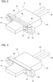
FIG. 2 is a perspective view of a wire harness according to the present embodiment. -
FIG. 3 is a perspective view of a housing for a connector according to the present embodiment. -
FIG. 4 is a perspective view of a sealing member according to the present embodiment. -
FIG. 5 is an enlarged cross-sectional view of the sealing member according to the present embodiment. -
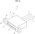
FIG. 6 is a perspective view of a mating wire harness of the connector according to the present embodiment. - Referring to the drawings, a detailed description is given below of a sealing member, a wire harness, and a connector according to the present embodiment. Note that dimensional ratios in the drawings are exaggerated for convenience of the description and may differ from actual ratios.
- As illustrated in
FIG. 1 , a connector 1 according to the present embodiment is applied to provide an electrical connection between electrical components (not illustrated), such as a power supply and an apparatus, or an apparatus and an apparatus. One electrical component has matingelectric wires mating housing 9 is electrically connected to the end parts of the matingelectric wires electric wires mating housing 9 make up amating wire harness 3. The other electrical component haselectric wires housing 27 is electrically connected to the end parts of theelectric wires electric wires housing 27 make up awire harness 5. In the connector 1, when themating housing 9 and thehousing 27 are fitted together, themating wire harness 3 and thewire harness 5 are electrically connected, and the electrical components are electrically connected to each other. - As illustrated in
FIGS. 1 to 6 , the connector 1 includes themating wire harness 3 and thewire harness 5. - As illustrated in
FIGS. 1 and6 , themating wire harness 3 includes the matingelectric wires mating housing 9. - In the present embodiment, there are two mating
electric wires 7. The ends of the matingelectric wires FIG. 1 are electrically connected to an electrical component. To the other ends of the matingelectric wires electric wires mating housing 9. - The
mating housing 9 includes a matinginner housing 11 and amating shield shell 13. - The mating
inner housing 11 is made from, for example, an insulating material such as a synthetic resin. The matinginner housing 11 is formed in a case shape capable of accommodating multiple (two in the present embodiment) mating terminals. The inside of the matinginner housing 11 is provided with elastically deformable mating locking lances (not illustrated) to be respectively engaged with the mating terminals. When the mating locking lances are respectively engaged with the mating terminals, the mating terminals are retained relative to the matinginner housing 11, and the mating terminals are held in the matinginner housing 11. - The
mating shield shell 13 is made from, for example, a conductive material such as metal. Themating shield shell 13 is formed in a case shape capable of accommodating the matinginner housing 11. The inside of themating shield shell 13 is provided with a mating engagement part (not illustrated) to be engaged with the matinginner housing 11 to hold the matinginner housing 11 in themating shield shell 13. Amating flange part 15 is provided on the front side of themating shield shell 13 in the direction of fitting with thehousing 27. The surface of themating flange part 15 on the front side in the fitting direction is amating fitting surface 17. On both sides of themating flange part 15 extending from the outer surface of themating shield shell 13,mating fixing parts mating flange part 15 and through whichbolts mating fixing parts mating fitting surface 17,nuts bolts electric wires mating housing 9, is electrically connected to themating shield shell 13. - As illustrated in
FIGS. 1 to 5 , thewire harness 5 includes theelectric wires housing 27, and a sealingmember 29. - In the present embodiment, there are two
electric wires 25. The ends of theelectric wires FIG. 1 are electrically connected to an electrical component. To the other ends of theelectric wires electric wires housing 27. - The
housing 27 includes aninner housing 31 and ashield shell 33. - The
inner housing 31 is made from, for example, an insulating material such as a synthetic resin. Theinner housing 31 is formed in a case shape capable of accommodating multiple (two in the present embodiment) terminals and capable of being fitted inside the matinginner housing 11. The inside of theinner housing 31 is provided with elastically deformable locking lances (not illustrated) to be respectively engaged with the terminals. When the locking lances are respectively engaged with the terminals, the terminals are retained relative to theinner housing 31, and the terminals are held in theinner housing 31. - When the
mating housing 9 and thehousing 27 are fitted together, theinner housing 31 is fitted to the matinginner housing 11. When the matinginner housing 11 and theinner housing 31 are fitted together, the mating terminals and the terminals are electrically connected, and the electrical components are electrically connected. - The
shield shell 33 is made from, for example, a conductive material such as metal. Theshield shell 33 is formed in a case shape capable of accommodating theinner housing 31. The inside of theshield shell 33 is provided with an engagement part (not illustrated) to be engaged with theinner housing 31 to hold theinner housing 31 in theshield shell 33. Note that a part of theinner housing 31 accommodated in theshield shell 33 is exposed from theshield shell 33, and the exposed part can be fitted inside the matinginner housing 11. Aflange part 35 is provided on the front side of theshield shell 33 in the direction of fitting with themating housing 9. The surface of theflange part 35 on the front side in the fitting direction is afitting surface 37. Theflange part 35 is provided with arib 39 protruding over thefitting surface 37. When themating housing 9 and thehousing 27 are fitted together, therib 39 comes into contact with a part of aside surface 15a of themating flange part 15 with the sealingmember 29 described below therebetween, and positions the fitting position between themating housing 9 and thehousing 27. On both sides of theflange part 35 extending from the outer surface of theshield shell 33, fixingparts flange part 35 and through which thebolts bolts bolts parts fitting surface 37. A grounded shield member (not illustrated) covering the outer periphery of theelectric wires housing 27 is electrically connected to theshield shell 33. - When the
mating housing 9 and thehousing 27 are fitted together, theshield shell 33 is fitted to themating shield shell 13 in such a manner that themating fitting surface 17 of themating flange part 15 is in contact with thefitting surface 37 of theflange part 35. The fitting of themating shield shell 13 and theshield shell 33 is held by inserting thebolts mating fixing parts 21, 21 (seeFIG. 6 ) and the fixingparts bolts mating shield shell 13 and theshield shell 33 are fitted together, a shield circuit is formed to prevent the intrusion of noise from the outside and the leakage of noise to the outside. The sealingmember 29 is arranged on thefitting surface 37 of theflange part 35 of theshield shell 33. - Here, the sealing
member 29 is arranged so as to adhere closely to themating fitting surface 17 of themating flange part 15 and thefitting surface 37 of theflange part 35 in a state where themating housing 9 and thehousing 27 are fitted together. When the sealingmember 29 adheres closely to themating fitting surface 17 and thefitting surface 37, sealing is realized between themating housing 9 and thehousing 27, and it is possible to prevent water, oil, or the like from entering the inside of themating housing 9 and the inside of thehousing 27. - A conventional sealing member is formed of a single sealing material, for example, an elastic material such as rubber. A sealing member formed of a single sealing material has high close adhesion to the
mating fitting surface 17 and thefitting surface 37 and has excellent sealing properties, but has low rigidity and easily deforms. Consequently, when a conventional sealing member interferes with, for example, therib 39, it deforms and lifts up from themating fitting surface 17 and thefitting surface 37 at the part where it has interfered, and there has been a possibility of a gap forming between themating fitting surface 17 and thefitting surface 37, resulting in reduced sealing properties. - Thus, the sealing
member 29 includes sealingmaterials high rigidity material 45. - Each of the sealing
materials 43 is made from, for example, an elastic material such as ethylene propylene diene rubber (EPDM). Each sealingmaterial 43 is formed into a sponge shape and a sheet shape, for example. The sealingmaterials materials 43. - The
high rigidity material 45 is made from, for example, a synthetic resin material having rigidity higher than that of each of the sealingmaterials 43 or a metal material having rigidity higher than that of each of the sealingmaterials 43. Thehigh rigidity material 45 is formed in a plate shape equal to or thinner than each of the sealingmaterials high rigidity material 45 is arranged between theadjacent sealing materials materials high rigidity material 45 is arranged so as to be surrounded by theadjacent sealing materials adjacent sealing materials high rigidity material 45 are adhered closely and fixed to each other through adhesion or the like. Consequently, the entire outer surface of the sealingmember 29 is made from the sealingmaterials 43 without thehigh rigidity material 45 exposed. - The sealing
member 29 made from the sealingmaterials high rigidity material 45 is arranged on thefitting surface 37 of theflange part 35 of theshield shell 33, and includes aplanar part 47 and abent part 49. - The
planar part 47 is arranged between themating fitting surface 17 and thefitting surface 37 in a state where themating housing 9 and thehousing 27 are fitted together. Theplanar part 47 is provided by fixing the sealingmaterials high rigidity material 45 shaped in a planar shape. In theplanar part 47, the sealingmaterials mating fitting surface 17 and thefitting surface 37, respectively. - The
bent part 49 is formed to be continuous with theplanar part 47. In a state where themating housing 9 and thehousing 27 are fitted together, thebent part 49 is arranged between a part of theside surface 15a of themating flange part 15 and the outer surface of therib 39. Thebent part 49 is provided by fixing the sealingmaterials high rigidity material 45 shaped in accordance with the outer shape of therib 39. In thebent part 49, the sealingmaterials side surface 15a of themating flange part 15 and the outer surface of therib 39, respectively. Note that in the case where thehigh rigidity material 45 is made from a material that plastically deforms, after forming the sealingmember 29 in a planar shape, thehigh rigidity material 45 may plastically deform in accordance with the outer shape of therib 39 to provide thebent part 49. Note that at the bent corner of thebent part 49, a slit is provided along the longitudinal direction of therib 39 in thehigh rigidity material 45. By providing the slit in thehigh rigidity material 45, the corner of thebent part 49 is easily bent, and it becomes easier for the shape of thebent part 49 to follow the outer shape of therib 39. - In the sealing
member 29, for example, even when the sealingmember 29 interferes with therib 39, due to thehigh rigidity material 45, no deformation occurs. Consequently, no gap occurs between the sealingmember 29 and each of themating fitting surface 17 and thefitting surface 37, thereby stabilizing the sealing properties. In addition, as the sealingmember 29 includes theplanar part 47 and thebent part 49, the sealingmember 29 is shaped to match the shape of the mating member to be adhered closely. The state in which the sealingmember 29 is shaped is maintained by thehigh rigidity material 45 without deformation. Consequently, no gap occurs between the sealingmember 29 and the mating member to be adhered closely, thereby stabilizing the sealing properties. - Note that although the sealing
member 29 incudes theplanar part 47 and thebent part 49, theplanar part 47 may be provided alone without providing thebent part 49, for example. Even such a sealingmember 29 can suppress the occurrence of the deformation of theplanar part 47 and the occurrence of a gap between theplanar part 47 and each of themating fitting surface 17 and thefitting surface 37. In the sealingmember 29, thehigh rigidity material 45 is arranged between theadjacent sealing materials high rigidity material 45 may be arranged only on one side of one sealingmaterial 43. In this case, the sealingmaterial 43 may be arranged to protrude from the outer edge of thehigh rigidity material 45 in order to cause the sealingmaterial 43 to closely adhere to the mating member. In addition, thehigh rigidity material 45 is not limited to a plate shape and may be any shape. For, example, thehigh rigidity material 45 may be formed in a linear shape, and multiple linearhigh rigidity materials 45 may be arranged in rows or in a lattice shape. - The sealing
member 29 includes at least one sealingmaterial 43 made from an elastic material, and ahigh rigidity material 45 provided as a single body with the at least one sealingmaterial 43 and having a rigidity higher than that of the at least one sealingmaterial 43. By providing thehigh rigidity material 45, the deformation of the sealingmaterial 43 can be suppressed. Consequently, the occurrence of a gap between the sealingmaterial 43 and a mating member to which the sealingmaterial 43 is adhered closely can be suppressed. - Therefore, such a sealing
member 29 can stabilize the sealing properties. - In addition, the at least one sealing
material 43 includes multiple sealingmaterials 43. Themultiple sealing materials 43 are arranged on top of each other. Thehigh rigidity material 45 is arranged between adjacent sealingmaterials material 43 can be increased, and the sealing properties can be improved. - Furthermore, the
wire harness 5 includes theelectric wires 25, thehousing 27 arranged at the end parts of theelectric wires 25, and the sealingmember 29 arranged at thefitting surface 37 of thehousing 27. When thehousing 27 is fitted to a mating member (mating housing 9 in the present embodiment), the sealingmember 29 arranged at thefitting surface 37 of thehousing 27 is adhered closely to the mating member. At this time, deformation of the sealingmember 29 is suppressed by thehigh rigidity material 45. Consequently, the occurrence of a gap between the sealingmember 29 and each of thefitting surface 37 and the mating member can be suppressed. - Therefore, the
wire harness 5 provided with the sealingmember 29 can stabilize the sealing properties. - The connector 1 includes the
housing 27, themating housing 9 which can be fitted to thehousing 27, and the sealingmember 29 arranged between thehousing 27 and themating housing 9 and adhered closely to thehousing 27 and themating housing 9. Deformation of the sealingmember 29 adhered closely to thehousing 27 and themating housing 9 is suppressed by thehigh rigidity material 45. Consequently, the occurrence of a gap between the sealingmember 29 and each of thehousing 27 and themating housing 9 can be suppressed. - Therefore, the connector 1 provided with the sealing
member 29 can stabilize the sealing properties. - Although the present embodiment has been described above, the present embodiment is not limited to these descriptions, and various modifications are possible within the scope of the gist of the present embodiment.
- For example, there are two sealing members according to the present embodiment, but the number thereof is not limited to this, and there may be three or more sealing members. In this case, a high rigidity material may be disposed between each of multiple sets of adjacent sealing materials. In addition, the outer edge of the high rigidity material may be covered with adjacent sealing materials to eliminate exposure of the high rigidity material, and the entire outer surface of the sealing member may be used as a sealing material. Furthermore, a high rigidity material may be embedded in one sealing material.
- In addition, the sealing member according to the present embodiment includes a planar part and a bent part, but the configuration is not limited thereto, and the sealing member may be shaped according to the shape of a mating member to be arranged in close adhesion, for example, so as to only include the planar part or only include the bent part. The shaped sealing member can maintain its shape due to the high rigidity material.
- Furthermore, the sealing member according to the present embodiment is arranged between a housing and a mating housing but is not limited to this arrangement, and the sealing member may be arranged between any members, for example, between a case member and a panel member.
- In the wire harness according to the present embodiment, a housing is fitted to a mating housing, but the configuration is not limited thereto. For example, the fitting surface of the housing may be mounted on a wall surface of a case member or panel member. Even in such a case, a sealing member arranged on the fitting surface of the housing closely adheres to the wall surface of the case member or panel member and can seal a gap between the housing and the case member or panel member. In addition, in the present embodiment, there are two electric wires, but the number thereof is not limited to this, and there may be one, or three or more electric wires. Similarly, in the present embodiment, there are two mating electric wires, but the number is not limited to this, and there may be one, or three or more mating electric wires.
- Furthermore, in the connector according to the present embodiment, the housing includes a shield shell and an inner housing, and the mating housing includes a mating shield shell and a mating inner housing, but the configuration is not limited thereto. For example, the housing and mating housing may be made as one member and may be made so that they can be fitted to each other, and a sealing member may be arranged between the housing and the mating housing. In addition, although the sealing member is arranged in the housing in the state before the housing and mating housing are fitted together, the arrangement is not limited thereto, and the sealing member may be arranged in the mating housing.
- Although the present invention has been described above by reference to the embodiment, the present invention is not limited to those and the configuration of parts can be replaced with any configuration having a similar function, as long as they lie within the scope of the claims.
Claims (4)
- A sealing member (29), comprising:at least one sealing material (43) made from an elastic material; anda high rigidity material (45) provided as a single body with the at least one sealing material (43) and having a rigidity higher than a rigidity of the at least one sealing material (43).
- The sealing member (29) according to claim 1, whereinthe at least one sealing material (43) includes a plurality of sealing materials (43),the plurality of sealing materials (43) are arranged on top of each other, andthe high rigidity material (45) is arranged between adjacent sealing materials (43).
- A wire harness (5), comprising:an electric wire (25);a housing (27) arranged at an end part of the electric wire (25); andthe sealing member (29) according to claim 1 or 2, arranged on a fitting surface (37) of the housing (27).
- A connector (1), comprising:a housing (27);a mating housing (9) that can be fitted to the housing (27); andthe sealing member (29) according to claim 1 or 2, arranged between the housing (27) and the mating housing (9) and adhered closely to the housing (27) and the mating housing (9).
Applications Claiming Priority (1)
| Application Number | Priority Date | Filing Date | Title |
|---|---|---|---|
| JP2022184840A JP7715698B2 (en) | 2022-11-18 | 2022-11-18 | Seal member, wire harness with seal member, and connector with seal member |
Publications (2)
| Publication Number | Publication Date |
|---|---|
| EP4372927A1 true EP4372927A1 (en) | 2024-05-22 |
| EP4372927B1 EP4372927B1 (en) | 2025-02-19 |
Family
ID=88793325
Family Applications (1)
| Application Number | Title | Priority Date | Filing Date |
|---|---|---|---|
| EP23209492.0A Active EP4372927B1 (en) | 2022-11-18 | 2023-11-13 | Sealing member, wire harness provided with sealing member, connector provided with sealing member |
Country Status (4)
| Country | Link |
|---|---|
| US (1) | US20240154354A1 (en) |
| EP (1) | EP4372927B1 (en) |
| JP (1) | JP7715698B2 (en) |
| CN (1) | CN118057678A (en) |
Citations (5)
| Publication number | Priority date | Publication date | Assignee | Title |
|---|---|---|---|---|
| JP2010211933A (en) | 2009-03-06 | 2010-09-24 | Yazaki Corp | Waterproof terminal block |
| US20180115104A1 (en) * | 2016-10-25 | 2018-04-26 | Yazaki Corporation | Connector |
| US9989578B2 (en) * | 2015-06-24 | 2018-06-05 | Ford Global Technologies, Llc | Self-warning system for unlocked connectors |
| US20220136606A1 (en) * | 2020-10-29 | 2022-05-05 | Aptiv Technologies Limited | Dispensing seal |
| JP7107812B2 (en) * | 2018-10-26 | 2022-07-27 | ミツミ電機株式会社 | electrical connectors and electronic devices |
Family Cites Families (5)
| Publication number | Priority date | Publication date | Assignee | Title |
|---|---|---|---|---|
| JPH0644684Y2 (en) * | 1988-06-14 | 1994-11-16 | 第二しなのポリマー株式会社 | Dummy connector |
| JP2535891Y2 (en) * | 1990-11-27 | 1997-05-14 | 菱星電装株式会社 | Sealing member for waterproof connector |
| JPH10321288A (en) * | 1997-05-21 | 1998-12-04 | Ryosei Denso Kk | Sealing member for water-proof connector |
| US7762559B2 (en) * | 2005-04-22 | 2010-07-27 | Nok Corporation | Gasket |
| JP6671862B2 (en) * | 2015-05-08 | 2020-03-25 | 矢崎総業株式会社 | Packing, connector and wire harness |
-
2022
- 2022-11-18 JP JP2022184840A patent/JP7715698B2/en active Active
-
2023
- 2023-11-13 EP EP23209492.0A patent/EP4372927B1/en active Active
- 2023-11-15 US US18/510,027 patent/US20240154354A1/en active Pending
- 2023-11-17 CN CN202311535926.6A patent/CN118057678A/en active Pending
Patent Citations (5)
| Publication number | Priority date | Publication date | Assignee | Title |
|---|---|---|---|---|
| JP2010211933A (en) | 2009-03-06 | 2010-09-24 | Yazaki Corp | Waterproof terminal block |
| US9989578B2 (en) * | 2015-06-24 | 2018-06-05 | Ford Global Technologies, Llc | Self-warning system for unlocked connectors |
| US20180115104A1 (en) * | 2016-10-25 | 2018-04-26 | Yazaki Corporation | Connector |
| JP7107812B2 (en) * | 2018-10-26 | 2022-07-27 | ミツミ電機株式会社 | electrical connectors and electronic devices |
| US20220136606A1 (en) * | 2020-10-29 | 2022-05-05 | Aptiv Technologies Limited | Dispensing seal |
Also Published As
| Publication number | Publication date |
|---|---|
| CN118057678A (en) | 2024-05-21 |
| US20240154354A1 (en) | 2024-05-09 |
| JP7715698B2 (en) | 2025-07-30 |
| JP2024073878A (en) | 2024-05-30 |
| EP4372927B1 (en) | 2025-02-19 |
Similar Documents
| Publication | Publication Date | Title |
|---|---|---|
| US10367292B2 (en) | Seal member and electrical connector | |
| US10224666B2 (en) | Packing and shield connector | |
| US7575476B2 (en) | Power distribution module and header assembly therefor | |
| US9083107B2 (en) | Connector | |
| US9343821B2 (en) | Terminal waterproofing structure of wire harness | |
| EP3166186B1 (en) | Electromagnetically shielded connector system | |
| US5586909A (en) | Sealing structure for a panel-mounted electrical connector | |
| US10490931B2 (en) | Seal member and electrical connector | |
| US4688868A (en) | Grounding gasket for D-shell connector | |
| JP7366833B2 (en) | Terminal block | |
| US20160056590A1 (en) | Connector | |
| US5564948A (en) | Shielded, printed circuit board, plug-in connection | |
| JP2015531538A (en) | Electrical connector | |
| US7077696B2 (en) | Connector which can easily be mounted to an object and provided with EMI protection | |
| US11081829B2 (en) | Connector | |
| CN112928523A (en) | Floatable connector and wire harness tray | |
| JP2020129506A (en) | connector | |
| US12088033B2 (en) | Electrical plug, electrical device, electrical plug connection, and method for producing an electrical device | |
| EP4372927B1 (en) | Sealing member, wire harness provided with sealing member, connector provided with sealing member | |
| US3371147A (en) | High frequency shielding and sealing gasket | |
| JP2015088233A (en) | connector | |
| US12431668B2 (en) | Shield connector | |
| US11158977B2 (en) | Connector including guiding structure between cover and housing | |
| JP2020095891A (en) | connector | |
| JP2022107260A (en) | Structure for fixing rear holder |
Legal Events
| Date | Code | Title | Description |
|---|---|---|---|
| PUAI | Public reference made under article 153(3) epc to a published international application that has entered the european phase |
Free format text: ORIGINAL CODE: 0009012 |
|
| STAA | Information on the status of an ep patent application or granted ep patent |
Free format text: STATUS: REQUEST FOR EXAMINATION WAS MADE |
|
| 17P | Request for examination filed |
Effective date: 20231113 |
|
| AK | Designated contracting states |
Kind code of ref document: A1 Designated state(s): AL AT BE BG CH CY CZ DE DK EE ES FI FR GB GR HR HU IE IS IT LI LT LU LV MC ME MK MT NL NO PL PT RO RS SE SI SK SM TR |
|
| STAA | Information on the status of an ep patent application or granted ep patent |
Free format text: STATUS: EXAMINATION IS IN PROGRESS |
|
| 17Q | First examination report despatched |
Effective date: 20240718 |
|
| GRAP | Despatch of communication of intention to grant a patent |
Free format text: ORIGINAL CODE: EPIDOSNIGR1 |
|
| STAA | Information on the status of an ep patent application or granted ep patent |
Free format text: STATUS: GRANT OF PATENT IS INTENDED |
|
| INTG | Intention to grant announced |
Effective date: 20241022 |
|
| GRAS | Grant fee paid |
Free format text: ORIGINAL CODE: EPIDOSNIGR3 |
|
| GRAA | (expected) grant |
Free format text: ORIGINAL CODE: 0009210 |
|
| STAA | Information on the status of an ep patent application or granted ep patent |
Free format text: STATUS: THE PATENT HAS BEEN GRANTED |
|
| AK | Designated contracting states |
Kind code of ref document: B1 Designated state(s): AL AT BE BG CH CY CZ DE DK EE ES FI FR GB GR HR HU IE IS IT LI LT LU LV MC ME MK MT NL NO PL PT RO RS SE SI SK SM TR |
|
| REG | Reference to a national code |
Ref country code: GB Ref legal event code: FG4D |
|
| REG | Reference to a national code |
Ref country code: CH Ref legal event code: EP |
|
| REG | Reference to a national code |
Ref country code: DE Ref legal event code: R096 Ref document number: 602023002114 Country of ref document: DE |
|
| REG | Reference to a national code |
Ref country code: IE Ref legal event code: FG4D |
|
| REG | Reference to a national code |
Ref country code: NL Ref legal event code: MP Effective date: 20250219 |
|
| PG25 | Lapsed in a contracting state [announced via postgrant information from national office to epo] |
Ref country code: RS Free format text: LAPSE BECAUSE OF FAILURE TO SUBMIT A TRANSLATION OF THE DESCRIPTION OR TO PAY THE FEE WITHIN THE PRESCRIBED TIME-LIMIT Effective date: 20250519 |
|
| PG25 | Lapsed in a contracting state [announced via postgrant information from national office to epo] |
Ref country code: FI Free format text: LAPSE BECAUSE OF FAILURE TO SUBMIT A TRANSLATION OF THE DESCRIPTION OR TO PAY THE FEE WITHIN THE PRESCRIBED TIME-LIMIT Effective date: 20250219 |
|
| PG25 | Lapsed in a contracting state [announced via postgrant information from national office to epo] |
Ref country code: PL Free format text: LAPSE BECAUSE OF FAILURE TO SUBMIT A TRANSLATION OF THE DESCRIPTION OR TO PAY THE FEE WITHIN THE PRESCRIBED TIME-LIMIT Effective date: 20250219 |
|
| PG25 | Lapsed in a contracting state [announced via postgrant information from national office to epo] |
Ref country code: ES Free format text: LAPSE BECAUSE OF FAILURE TO SUBMIT A TRANSLATION OF THE DESCRIPTION OR TO PAY THE FEE WITHIN THE PRESCRIBED TIME-LIMIT Effective date: 20250219 |
|
| REG | Reference to a national code |
Ref country code: LT Ref legal event code: MG9D |
|
| PG25 | Lapsed in a contracting state [announced via postgrant information from national office to epo] |
Ref country code: IS Free format text: LAPSE BECAUSE OF FAILURE TO SUBMIT A TRANSLATION OF THE DESCRIPTION OR TO PAY THE FEE WITHIN THE PRESCRIBED TIME-LIMIT Effective date: 20250619 Ref country code: NO Free format text: LAPSE BECAUSE OF FAILURE TO SUBMIT A TRANSLATION OF THE DESCRIPTION OR TO PAY THE FEE WITHIN THE PRESCRIBED TIME-LIMIT Effective date: 20250519 |
|
| PG25 | Lapsed in a contracting state [announced via postgrant information from national office to epo] |
Ref country code: NL Free format text: LAPSE BECAUSE OF FAILURE TO SUBMIT A TRANSLATION OF THE DESCRIPTION OR TO PAY THE FEE WITHIN THE PRESCRIBED TIME-LIMIT Effective date: 20250219 |
|
| PG25 | Lapsed in a contracting state [announced via postgrant information from national office to epo] |
Ref country code: HR Free format text: LAPSE BECAUSE OF FAILURE TO SUBMIT A TRANSLATION OF THE DESCRIPTION OR TO PAY THE FEE WITHIN THE PRESCRIBED TIME-LIMIT Effective date: 20250219 |
|
| PG25 | Lapsed in a contracting state [announced via postgrant information from national office to epo] |
Ref country code: LV Free format text: LAPSE BECAUSE OF FAILURE TO SUBMIT A TRANSLATION OF THE DESCRIPTION OR TO PAY THE FEE WITHIN THE PRESCRIBED TIME-LIMIT Effective date: 20250219 Ref country code: PT Free format text: LAPSE BECAUSE OF FAILURE TO SUBMIT A TRANSLATION OF THE DESCRIPTION OR TO PAY THE FEE WITHIN THE PRESCRIBED TIME-LIMIT Effective date: 20250620 |
|
| PG25 | Lapsed in a contracting state [announced via postgrant information from national office to epo] |
Ref country code: BG Free format text: LAPSE BECAUSE OF FAILURE TO SUBMIT A TRANSLATION OF THE DESCRIPTION OR TO PAY THE FEE WITHIN THE PRESCRIBED TIME-LIMIT Effective date: 20250219 Ref country code: GR Free format text: LAPSE BECAUSE OF FAILURE TO SUBMIT A TRANSLATION OF THE DESCRIPTION OR TO PAY THE FEE WITHIN THE PRESCRIBED TIME-LIMIT Effective date: 20250520 |
|
| PG25 | Lapsed in a contracting state [announced via postgrant information from national office to epo] |
Ref country code: SE Free format text: LAPSE BECAUSE OF FAILURE TO SUBMIT A TRANSLATION OF THE DESCRIPTION OR TO PAY THE FEE WITHIN THE PRESCRIBED TIME-LIMIT Effective date: 20250219 |
|
| PG25 | Lapsed in a contracting state [announced via postgrant information from national office to epo] |
Ref country code: SM Free format text: LAPSE BECAUSE OF FAILURE TO SUBMIT A TRANSLATION OF THE DESCRIPTION OR TO PAY THE FEE WITHIN THE PRESCRIBED TIME-LIMIT Effective date: 20250219 |
|
| PG25 | Lapsed in a contracting state [announced via postgrant information from national office to epo] |
Ref country code: DK Free format text: LAPSE BECAUSE OF FAILURE TO SUBMIT A TRANSLATION OF THE DESCRIPTION OR TO PAY THE FEE WITHIN THE PRESCRIBED TIME-LIMIT Effective date: 20250219 |
|
| PG25 | Lapsed in a contracting state [announced via postgrant information from national office to epo] |
Ref country code: IT Free format text: LAPSE BECAUSE OF FAILURE TO SUBMIT A TRANSLATION OF THE DESCRIPTION OR TO PAY THE FEE WITHIN THE PRESCRIBED TIME-LIMIT Effective date: 20250219 |
|
| PG25 | Lapsed in a contracting state [announced via postgrant information from national office to epo] |
Ref country code: AT Free format text: LAPSE BECAUSE OF FAILURE TO SUBMIT A TRANSLATION OF THE DESCRIPTION OR TO PAY THE FEE WITHIN THE PRESCRIBED TIME-LIMIT Effective date: 20250219 |
|
| PG25 | Lapsed in a contracting state [announced via postgrant information from national office to epo] |
Ref country code: EE Free format text: LAPSE BECAUSE OF FAILURE TO SUBMIT A TRANSLATION OF THE DESCRIPTION OR TO PAY THE FEE WITHIN THE PRESCRIBED TIME-LIMIT Effective date: 20250219 Ref country code: CZ Free format text: LAPSE BECAUSE OF FAILURE TO SUBMIT A TRANSLATION OF THE DESCRIPTION OR TO PAY THE FEE WITHIN THE PRESCRIBED TIME-LIMIT Effective date: 20250219 |
|
| PG25 | Lapsed in a contracting state [announced via postgrant information from national office to epo] |
Ref country code: RO Free format text: LAPSE BECAUSE OF FAILURE TO SUBMIT A TRANSLATION OF THE DESCRIPTION OR TO PAY THE FEE WITHIN THE PRESCRIBED TIME-LIMIT Effective date: 20250219 |
|
| PG25 | Lapsed in a contracting state [announced via postgrant information from national office to epo] |
Ref country code: SK Free format text: LAPSE BECAUSE OF FAILURE TO SUBMIT A TRANSLATION OF THE DESCRIPTION OR TO PAY THE FEE WITHIN THE PRESCRIBED TIME-LIMIT Effective date: 20250219 |
|
| REG | Reference to a national code |
Ref country code: DE Ref legal event code: R097 Ref document number: 602023002114 Country of ref document: DE |
|
| PLBE | No opposition filed within time limit |
Free format text: ORIGINAL CODE: 0009261 |
|
| STAA | Information on the status of an ep patent application or granted ep patent |
Free format text: STATUS: NO OPPOSITION FILED WITHIN TIME LIMIT |
|
| PGFP | Annual fee paid to national office [announced via postgrant information from national office to epo] |
Ref country code: DE Payment date: 20250930 Year of fee payment: 3 |
|
| 26N | No opposition filed |
Effective date: 20251120 |