EP4372891A1 - Battery device and preparation method therefor - Google Patents
Battery device and preparation method therefor Download PDFInfo
- Publication number
- EP4372891A1 EP4372891A1 EP21949906.8A EP21949906A EP4372891A1 EP 4372891 A1 EP4372891 A1 EP 4372891A1 EP 21949906 A EP21949906 A EP 21949906A EP 4372891 A1 EP4372891 A1 EP 4372891A1
- Authority
- EP
- European Patent Office
- Prior art keywords
- liquid cooling
- plate
- battery module
- cooling plate
- bottom plate
- Prior art date
- Legal status (The legal status is an assumption and is not a legal conclusion. Google has not performed a legal analysis and makes no representation as to the accuracy of the status listed.)
- Withdrawn
Links
Images

Classifications
-
- H—ELECTRICITY
- H01—ELECTRIC ELEMENTS
- H01M—PROCESSES OR MEANS, e.g. BATTERIES, FOR THE DIRECT CONVERSION OF CHEMICAL ENERGY INTO ELECTRICAL ENERGY
- H01M50/00—Constructional details or processes of manufacture of the non-active parts of electrochemical cells other than fuel cells, e.g. hybrid cells
- H01M50/30—Arrangements for facilitating escape of gases
- H01M50/383—Flame arresting or ignition-preventing means
-
- H—ELECTRICITY
- H01—ELECTRIC ELEMENTS
- H01M—PROCESSES OR MEANS, e.g. BATTERIES, FOR THE DIRECT CONVERSION OF CHEMICAL ENERGY INTO ELECTRICAL ENERGY
- H01M10/00—Secondary cells; Manufacture thereof
- H01M10/60—Heating or cooling; Temperature control
- H01M10/65—Means for temperature control structurally associated with the cells
- H01M10/655—Solid structures for heat exchange or heat conduction
- H01M10/6556—Solid parts with flow channel passages or pipes for heat exchange
-
- H—ELECTRICITY
- H01—ELECTRIC ELEMENTS
- H01M—PROCESSES OR MEANS, e.g. BATTERIES, FOR THE DIRECT CONVERSION OF CHEMICAL ENERGY INTO ELECTRICAL ENERGY
- H01M10/00—Secondary cells; Manufacture thereof
- H01M10/04—Construction or manufacture in general
-
- H—ELECTRICITY
- H01—ELECTRIC ELEMENTS
- H01M—PROCESSES OR MEANS, e.g. BATTERIES, FOR THE DIRECT CONVERSION OF CHEMICAL ENERGY INTO ELECTRICAL ENERGY
- H01M10/00—Secondary cells; Manufacture thereof
- H01M10/60—Heating or cooling; Temperature control
- H01M10/61—Types of temperature control
- H01M10/613—Cooling or keeping cold
-
- H—ELECTRICITY
- H01—ELECTRIC ELEMENTS
- H01M—PROCESSES OR MEANS, e.g. BATTERIES, FOR THE DIRECT CONVERSION OF CHEMICAL ENERGY INTO ELECTRICAL ENERGY
- H01M10/00—Secondary cells; Manufacture thereof
- H01M10/60—Heating or cooling; Temperature control
- H01M10/62—Heating or cooling; Temperature control specially adapted for specific applications
- H01M10/625—Vehicles
-
- H—ELECTRICITY
- H01—ELECTRIC ELEMENTS
- H01M—PROCESSES OR MEANS, e.g. BATTERIES, FOR THE DIRECT CONVERSION OF CHEMICAL ENERGY INTO ELECTRICAL ENERGY
- H01M10/00—Secondary cells; Manufacture thereof
- H01M10/60—Heating or cooling; Temperature control
- H01M10/65—Means for temperature control structurally associated with the cells
- H01M10/655—Solid structures for heat exchange or heat conduction
- H01M10/6554—Rods or plates
-
- H—ELECTRICITY
- H01—ELECTRIC ELEMENTS
- H01M—PROCESSES OR MEANS, e.g. BATTERIES, FOR THE DIRECT CONVERSION OF CHEMICAL ENERGY INTO ELECTRICAL ENERGY
- H01M10/00—Secondary cells; Manufacture thereof
- H01M10/60—Heating or cooling; Temperature control
- H01M10/65—Means for temperature control structurally associated with the cells
- H01M10/656—Means for temperature control structurally associated with the cells characterised by the type of heat-exchange fluid
- H01M10/6567—Liquids
-
- H—ELECTRICITY
- H01—ELECTRIC ELEMENTS
- H01M—PROCESSES OR MEANS, e.g. BATTERIES, FOR THE DIRECT CONVERSION OF CHEMICAL ENERGY INTO ELECTRICAL ENERGY
- H01M50/00—Constructional details or processes of manufacture of the non-active parts of electrochemical cells other than fuel cells, e.g. hybrid cells
- H01M50/20—Mountings; Secondary casings or frames; Racks, modules or packs; Suspension devices; Shock absorbers; Transport or carrying devices; Holders
- H01M50/204—Racks, modules or packs for multiple batteries or multiple cells
-
- H—ELECTRICITY
- H01—ELECTRIC ELEMENTS
- H01M—PROCESSES OR MEANS, e.g. BATTERIES, FOR THE DIRECT CONVERSION OF CHEMICAL ENERGY INTO ELECTRICAL ENERGY
- H01M50/00—Constructional details or processes of manufacture of the non-active parts of electrochemical cells other than fuel cells, e.g. hybrid cells
- H01M50/20—Mountings; Secondary casings or frames; Racks, modules or packs; Suspension devices; Shock absorbers; Transport or carrying devices; Holders
- H01M50/244—Secondary casings; Racks; Suspension devices; Carrying devices; Holders characterised by their mounting method
-
- H—ELECTRICITY
- H01—ELECTRIC ELEMENTS
- H01M—PROCESSES OR MEANS, e.g. BATTERIES, FOR THE DIRECT CONVERSION OF CHEMICAL ENERGY INTO ELECTRICAL ENERGY
- H01M50/00—Constructional details or processes of manufacture of the non-active parts of electrochemical cells other than fuel cells, e.g. hybrid cells
- H01M50/20—Mountings; Secondary casings or frames; Racks, modules or packs; Suspension devices; Shock absorbers; Transport or carrying devices; Holders
- H01M50/249—Mountings; Secondary casings or frames; Racks, modules or packs; Suspension devices; Shock absorbers; Transport or carrying devices; Holders specially adapted for aircraft or vehicles, e.g. cars or trains
-
- H—ELECTRICITY
- H01—ELECTRIC ELEMENTS
- H01M—PROCESSES OR MEANS, e.g. BATTERIES, FOR THE DIRECT CONVERSION OF CHEMICAL ENERGY INTO ELECTRICAL ENERGY
- H01M50/00—Constructional details or processes of manufacture of the non-active parts of electrochemical cells other than fuel cells, e.g. hybrid cells
- H01M50/20—Mountings; Secondary casings or frames; Racks, modules or packs; Suspension devices; Shock absorbers; Transport or carrying devices; Holders
- H01M50/271—Lids or covers for the racks or secondary casings
-
- H—ELECTRICITY
- H01—ELECTRIC ELEMENTS
- H01M—PROCESSES OR MEANS, e.g. BATTERIES, FOR THE DIRECT CONVERSION OF CHEMICAL ENERGY INTO ELECTRICAL ENERGY
- H01M50/00—Constructional details or processes of manufacture of the non-active parts of electrochemical cells other than fuel cells, e.g. hybrid cells
- H01M50/30—Arrangements for facilitating escape of gases
-
- H—ELECTRICITY
- H01—ELECTRIC ELEMENTS
- H01M—PROCESSES OR MEANS, e.g. BATTERIES, FOR THE DIRECT CONVERSION OF CHEMICAL ENERGY INTO ELECTRICAL ENERGY
- H01M50/00—Constructional details or processes of manufacture of the non-active parts of electrochemical cells other than fuel cells, e.g. hybrid cells
- H01M50/30—Arrangements for facilitating escape of gases
- H01M50/394—Gas-pervious parts or elements
-
- Y—GENERAL TAGGING OF NEW TECHNOLOGICAL DEVELOPMENTS; GENERAL TAGGING OF CROSS-SECTIONAL TECHNOLOGIES SPANNING OVER SEVERAL SECTIONS OF THE IPC; TECHNICAL SUBJECTS COVERED BY FORMER USPC CROSS-REFERENCE ART COLLECTIONS [XRACs] AND DIGESTS
- Y02—TECHNOLOGIES OR APPLICATIONS FOR MITIGATION OR ADAPTATION AGAINST CLIMATE CHANGE
- Y02E—REDUCTION OF GREENHOUSE GAS [GHG] EMISSIONS, RELATED TO ENERGY GENERATION, TRANSMISSION OR DISTRIBUTION
- Y02E60/00—Enabling technologies; Technologies with a potential or indirect contribution to GHG emissions mitigation
- Y02E60/10—Energy storage using batteries
Definitions
- the present invention pertains to the field of battery technologies, and in particular, relates to a battery device and a preparation method therefor.
- a liquid cooling plate In a design of an existing battery device, a liquid cooling plate is usually located at a bottom of a device housing, or is integrated into the bottom of the housing. There are two main reasons. An air relief valve of a prismatic cell usually faces upward and should not face downward. Therefore, the liquid cooling plate usually performs cooling at a bottom of the cell. A pouch cell is limited by a structure design of a conventional vehicle. The liquid cooling plate is usually placed at the bottom of the device housing, and performs cooling on the module from the bottom. When thermal runaway occurs on a module and a cell inside the device, high-temperature gas and flame need to be quickly discharged to the outside of the device. According to the conventional design, some holes can be opened on a surface of the module to help discharge gas.
- the liquid cooling plate is located at the bottom of the device housing and the module needs to be fastened to the liquid cooling plate, a hole cannot be opened on a bottom surface of the module, but can be opened only on a side surface or a top of the module. Therefore, according to the existing device design, after thermal runaway occurs on the internal cell, the high-temperature gas and flame can be ejected only from a side plate, an end plate, and a cover plate.
- the high-temperature gas and flame easily transfer heat to an adjacent module or an inner wall of the device housing after being discharged outward through holes in the side plate and the end plate. Transferring the heat to the adjacent module causes thermal runaway on the adjacent module, resulting in mutual ejection. Consequently, fire or explosion occurs due to accumulation of excessive heat inside the device. Transferring the heat to the inner wall of the device housing causes the heat to be reflected back to the module again because there is no place to release the heat. Therefore, the heat is externally superposed on the module, aggravating an outbreak of the module.
- the high-temperature gas and flame inside the module easily burn through the cover plate of the device directly after being discharged outward through a hole in the cover plate, causing fire to spread to an upper part of the device, and posing a threat to a passenger compartment of the vehicle.
- the present invention provides a battery device.
- a battery device includes a housing, a battery module, and a liquid cooling plate; the battery module includes a cover plate and a bottom plate that are opposite to each other, where the cover plate of the battery module is attached to the liquid cooling plate; and the housing is configured to accommodate the battery module, the bottom plate of the battery module is provided with a plurality of exhaust holes, and there is a gap between the bottom plate of the battery module and a bottom of the housing.
- a beam is disposed inside the housing and the battery module is fastened to the beam.
- an explosion-proof valve is disposed at the bottom of the housing.
- distribution density of the plurality of exhaust holes on the bottom plate of the battery module is 8%-20%, wherein a value of the distribution density is equal to an area of the plurality of exhaust holes divided by an area of the bottom plate of the battery module.
- an aperture of the exhaust hole is 2 mm to 10 mm.
- a spacing between adjacent exhaust holes is 5 mm to 15 mm.
- an area of a single exhaust hole disposed at an edge of the bottom plate of the battery module is larger than an area of a single exhaust hole disposed at a center of the bottom plate of the battery module.
- the exhaust hole is sealed by using an insulation film.
- the gap between the bottom plate of the battery module and the bottom of the housing is 2 mm to 20 mm.
- the battery module comprises a pouch cell.
- the liquid cooling plate comprises a cover plate of the liquid cooling plate and a bottom plate of the liquid cooling plate that are opposite to each other, the cover plate of the liquid cooling plate has a plurality of recesses, and the cover plate of the liquid cooling plate is attached to the bottom plate of the liquid cooling plate through the recesses, wherein the plurality of recesses are arranged in a dot matrix, and are preferably arranged in a staggered manner.
- a distance between adjacent recesses is 15 mm to 20 mm.
- a depth of a flow channel of the liquid cooling plate is 2 mm to 5 mm.
- a thickness of the liquid cooling plate is 2 mm to 5 mm.
- a method for assembling the above-mentioned battery device includes the following steps:
- the method further includes connecting the obtained battery device to a vehicle.
- a liquid cooling plate includes a cover plate of the liquid cooling plate and a bottom plate of the liquid cooling plate that are opposite to each other, the cover plate of the liquid cooling plate has a plurality of recesses, and the cover plate of the liquid cooling plate is attached to the bottom plate of the liquid cooling plate through the recesses, where the plurality of recesses are arranged in a dot matrix, and are preferably arranged in a staggered manner.
- a distance between adjacent recesses is 15 mm to 20 mm.
- a depth of a flow channel of the liquid cooling plate is 2 mm to 5 mm.
- a thickness of the liquid cooling plate is 2 mm to 5 mm.
- a gap is reserved between the bottom of the module and the housing of the battery device, and a plurality of exhaust holes are provided at the bottom plate of the module, thereby effectively alleviating or resolving a thermal diffusion safety problem of a power battery of a new energy electric vehicle.
- thermal runaway occurs, high-temperature gas or flame generated inside the battery device due to the thermal runaway can be quickly discharged from a lower part of the battery device to the outside through the gap in the lower part and the explosion-proof valve, without being ejected around or upward, reducing damage to a passenger compartment of the vehicle.
- the battery device in the present invention may be optionally provided with no cover plate of the housing in terms of structure, thereby reducing mounting space, reducing a weight of the battery device, and reducing costs.
- the liquid cooling plate is disposed above the battery module, and does not need to bear a weight of the module, and is used only for cooling, so that a thickness of the liquid cooling plate can be reduced, and a weight of the battery device can be further reduced.
- dot-matrix arrangement of the cooling plate, especially staggered arrangement can achieve an optimal heat exchange effect.
- connection should be understood in a broad sense, for example, may be a fixed connection, may be a detachable connection or an integrated connection; may be a mechanical connection, or may be an electrical connection; and may be a direct connection, may be an indirect connection through an intermediate medium, or may be internal communication between two elements or an interaction relationship between two elements.
- connect may be a fixed connection, may be a detachable connection or an integrated connection; may be a mechanical connection, or may be an electrical connection; and may be a direct connection, may be an indirect connection through an intermediate medium, or may be internal communication between two elements or an interaction relationship between two elements.
- the present invention provides a battery device, where the battery device includes a housing, a battery module, and a liquid cooling plate; the battery module includes a cover plate and a bottom plate that are opposite to each other, where the cover plate of the battery module is attached to the liquid cooling plate; and the housing is configured to accommodate the battery module, the bottom plate of the battery module is provided with a plurality of exhaust holes, and there is a gap between the bottom plate of the battery module and a bottom of the housing.
- the battery device includes a housing, a battery module 1, and a liquid cooling plate 2;
- the battery module 1 includes a cover plate 11 of the battery module and a bottom plate 12 of the battery module that are opposite to each other, where the cover plate 11 of the battery module is attached to the liquid cooling plate 2.
- Attachment herein means that the cover plate 11 of the battery module is in direct contact with the liquid cooling plate 2.
- the liquid cooling plate is located at a bottom of the battery module, and the liquid cooling plate needs to be loaded into the housing first, and then the battery module is loaded into the housing, so that the battery module is attached to the liquid cooling plate.
- the liquid cooling plate 2 in the present invention is located above the cover plate of the battery module, and the liquid cooling plate 2 can be directly connected to a vehicle body, so that the vehicle body protects the liquid cooling plate, thereby enhancing mechanical strength of a top of the battery device.
- a conventional housing includes a bottom plate of the housing and a cover plate of the housing.
- the cover plate of the housing may be optionally not disposed in terms of structure, thereby reducing mounting space, reducing a weight of the battery device, and reducing costs.
- the liquid cooling plate 2 in the present invention may be any existing liquid cooling plate in the conventional technology, or may be the liquid cooling plate 2 shown in FIG. 5 and FIG. 6 .
- the liquid cooling plate 2 includes a cover plate 21 of the liquid cooling plate and a bottom plate 22 of the liquid cooling plate that are opposite to each other, the cover plate 21 of the liquid cooling plate has a plurality of recesses, and the cover plate 21 of the liquid cooling plate is attached to the bottom plate 22 of the liquid cooling plate through the recesses, where the plurality of recesses are arranged in a dot matrix, and are preferably arranged in a staggered manner.
- the staggered arrangement means that two adjacent rows of recesses are arranged in a staggered manner.
- a flow channel formed in this staggered arrangement manner ensures that cooling liquid in the flow channel does not flow in a straight line.
- the cooling liquid can flow in the flow channel 23 in a direction indicated by an arrow in FIG. 5 , that is, flow in the liquid cooling plate 2 in a staggered manner, thereby providing a better cooling effect.
- the cover plate 21 of the liquid cooling plate and the bottom plate 22 of the liquid cooling plate are two flat plates, and thicknesses of the two flat plates may be the same or different, for example, the thickness of each plate may be 1 mm.
- Materials of the cover plate 21 of the liquid cooling plate and the bottom plate 22 of the liquid cooling plate may be Al3003 or other Al of series 3.
- the recess of the cover plate 21 of the liquid cooling plate may be a part of a spherical shape or another shape of a recess.
- a processing technique of the bottom plate 22 of the liquid cooling plate and the cover plate 21 of the liquid cooling plate may be stamping, harmonica-type processing, or aluminum extrusion. Stamping with a lowest cost is preferably selected for processing and molding.
- a distance between two adjacent recesses is 15 mm to 20 mm.
- a depth of the flow channel 23 is 2 mm to 5 mm. The depth herein refers to a distance between the bottom plate 22 of the liquid cooling plate and the cover plate 21 of the liquid cooling plate in the corresponding flow channel 23.
- a thickness of the liquid cooling plate 2 is 2 mm to 5 mm.
- the thickness herein means that a maximum distance between an upper surface of the cover plate 21 of the liquid cooling plate and a lower surface of the bottom plate 22 of the liquid cooling plate is 2 mm to 5 mm.
- the above-mentioned structure of dot-matrix staggered arrangement of a plurality of recesses can achieve an optimal heat exchange effect.
- a simulation manner is used to compare a cooling effect of the dot-matrix staggered arrangement in the present invention with a cooling effect of using an S-shaped flow channel.
- a result shows that a temperature difference between a highest temperature and a lowest temperature in the structure of the dot-matrix staggered arrangement is 4.4°C, which is less than 4.7°C in the S-shaped flow channel.
- the battery module 1 further includes structures such as a cell, a busbar, end plates on two sides, and side plates on two sides.
- the cell can be specifically designed based on an actual need, which is not limited herein.
- the cell of the battery module 1 is a pouch cell.
- the pouch cell has no pressure relief valve and a cell placement manner is flexible and changeable so that cooling can be performed from all directions. Therefore, a top cooling manner can be used.
- the battery module and the beam are tightly attached to the liquid cooling plate without a gap, and air content inside the battery device is small and condensate water is not easily generated.
- the condensate water does not drip on electrified bodies such as positive and negative terminals of the module.
- the condensate water may only drip on a sampling plate of the battery module and a connector position of the sampling plate. Because these positions already meet waterproof requirements such as IP65, dripping of a small amount of condensate water drip has no impact on a function and electrical insulation of the battery module.
- the cover plate 11 of the battery module is attached to the liquid cooling plate 2.
- Attachment herein may refer to any manner of fastening, connection, adhesion, and the like in the conventional technology that needs to be used based on a specific design.
- the cover plate 11 of the battery module is fastened and attached to the liquid cooling plate 2 by using a thermally conductive adhesive, so that heat of the battery module is transferred by using the thermally conductive adhesive.
- the battery module 1 can be pre-tightened and stacked in a sequence of "end plate - cell (there are several cells, and a specific quantity is determined based on a capacity of the battery module) - end plate", and then tabs on two sides of the cell are welded to the busbar. Then, the side plates on two sides are respectively welded to the end plates on two sides, and finally, the cover plate 11 and the bottom plate 12 of the battery module are separately welded.
- the housing includes a housing body 5 and a bottom plate 3 of the housing, and a cavity formed by the housing body 5 and the bottom plate 3 of the housing is used to accommodate the battery module 1.
- a shape of the housing can be adjusted based on a structure of the battery module 1 or a specific design need.
- a beam 4 is disposed inside the housing, and the battery module 1 is fastened to the beam 4.
- the battery module 1 can be fastened to the beam 4 through bolted connection.
- the beam 4 can be designed by using any solution known in the conventional technology, for example, may be a crossbeam, a longitudinal beam, or another type of beam.
- the bottom plate 12 of the battery module is provided with a plurality of exhaust holes 7.
- the exhaust hole 7 is configured to discharge high-temperature gas or flame generated by the cell to the outside of the battery device.
- a shape, a spacing, a quantity, and the like of exhaust holes 7 are not limited in terms of design, and can be flexibly designed as needed.
- distribution density of the plurality of exhaust holes 7 on the bottom plate 12 of the battery module is 8%-20%.
- a value of the distribution density is equal to an area of the plurality of exhaust holes divided by an area of the bottom plate of the battery module.
- the distribution density of the plurality of exhaust holes 7 on the bottom plate 12 of the battery module is 0.2.
- the exhaust holes 7 may be in any shape, for example, may be in a circular shape, a kidney shape, an oval shape, a triangular shape, a quadrilateral shape, or another regular or irregular shape.
- the exhaust holes 7 may be in a same shape, or may be a combination of two or more shapes.
- the exhaust hole is a circle with an aperture of 2 mm to 10 mm.
- the exhaust hole 7 is a combination of a kidney shape and a circular shape.
- the kidney-shaped exhaust hole is provided at an edge position of the bottom plate 12 of the battery module, that is, a position away from a center of the bottom plate 12 of the battery module.
- the circular exhaust hole is provided at a position closer to the center of the bottom plate 12 of the battery module relative to the kidney-shaped exhaust hole, and an area of a single kidney-shaped exhaust hole is larger than an area of a single circular exhaust hole.
- a total area of the kidney-shaped exhaust holes is 15372 mm 2 and a total area of the circular exhaust holes is 11290 mm 2 .
- a spacing between two adjacent exhaust holes 7 is 8 mm to 15 mm.
- the exhaust hole 7 is sealed by using an insulation film.
- the insulation film mainly serves to prevent foreign matters from entering the module and improve the electrical insulation performance of the module.
- the gap between the bottom plate 12 of the battery module and the bottom of the housing is conducive to heat diffusion, so that high-temperature gas or flame generated by the cell is not blocked by the housing, and further discharged from the bottom of the housing, without posing a serious threat to a passenger compartment of a vehicle.
- the gap between the bottom plate 12 of the battery module and the bottom of the housing is 2 mm to 20 mm, for example, may be 2 mm, 3 mm, 4 mm, 5 mm, 6 mm, 7 mm, 8 mm, 9 mm, 10 mm, 11 mm, 12 mm, 13 mm, 14 mm, 15 mm, 16 mm, 17 mm, 18 mm, 19 mm, or 20 mm.
- the gap between the bottom plate 12 of the battery module and the bottom of the housing refers to a distance between the bottom plate 12 of the battery module and the bottom plate 3 of the housing.
- an explosion-proof valve 6 is disposed at the bottom of the housing, that is, an explosion-proof valve is disposed on the bottom plate 3 of the housing, and is configured to discharge the high-temperature gas or flame generated by the cell to the outside of the battery device through the exhaust hole 7 and the explosion-proof valve 6 successively.
- a structure of the explosion-proof valve 6 may be an explosion-proof valve structure known in the conventional technology, and a quantity of the explosion-proof valve 6 may be adjusted based on an actual need.
- the explosion-proof valve 6 may alternatively be replaced with another similar product of a film type or a mesh shape, provided that a gas discharge function can be implemented.
- the battery device further includes a battery management system and a battery protection apparatus.
- the present invention further provides a method for assembling the above-mentioned battery device.
- the method includes the following steps: fastening a liquid cooling plate to a housing body and performing upside-down flipping by 180 degrees; fastening a battery module inside the housing body, so that a cover plate of the battery module is attached to the liquid cooling plate; and fastening a bottom plate of a housing to the housing body and performing upside-down flipping by 180 degrees to obtain the battery device.
- the method further includes connecting the obtained battery device to a vehicle.
- the battery device in the present invention can be assembled in the following manner: First, the liquid cooling plate and the housing body are fastened by using a structural adhesive and/or a bolt, and then flipped upside down by 180 degrees after the fastening (in this case, the liquid cooling plate is located at the bottom). Then, the battery module is placed into the housing body. The battery module is not fastened to the bottom plate of the housing in a conventional manner. Instead, the module is flipped upside down by 180 degrees and then flanges on two sides of the battery module are fastened, through bolted connection, to beams that are connected to two ends of the housing. The battery module is connected to the liquid cooling plate by using a thermally conductive adhesive.
- the bottom plate of the housing is fastened to the housing body by using a structural adhesive and bolted connection.
- the assembled battery device is flipped upside down by 180 degrees again (in this case, the liquid cooling plate is located at the top and the bottom plate of the housing is located at the bottom), and can be further connected to a vehicle.
- heat transfer is performed between the top of the battery module and the liquid cooling plate by using a thermally conductive adhesive.
- the flange of the module is hung on the beam of the housing through bolted connection. There is a gap of 2 mm to 20 mm between the bottom of the battery module and the bottom of the housing.
- a battery device includes a housing, a battery module 1, and a liquid cooling plate 2; the battery module 1 includes a cover plate 11 of the battery module and a bottom plate 12 of the battery module that are opposite to each other, where the cover plate 11 of the battery module is fastened and attached to the liquid cooling plate 2 by using a thermally conductive adhesive; and the housing is configured to accommodate the battery module 1, and four explosion-proof valves are disposed at the bottom of the housing, that is, on the bottom plate 3 of the housing.
- a crossbeam 4 is disposed inside the housing, and the battery module 1 is fastened to the crossbeam 4 through bolted connection.
- a cell in the battery module 1 is a pouch cell.
- An area of the bottom plate 12 of the battery module is 180588 mm 2 , 648 exhaust holes 7 are disposed, and each exhaust hole 7 is sealed by using an insulation film.
- the exhaust hole 7 is a combination of a kidney shape and a circular shape. As shown in FIG. 3 , the kidney-shaped exhaust hole is provided at an edge position of the bottom plate 12 of the battery module, the circular exhaust hole is provided at a position closer to the center of the bottom plate 12 of the battery module relative to the kidney-shaped exhaust hole, an area of a single kidney-shaped exhaust hole is 213.5 mm 2 , and an area of a single circular exhaust hole is 19.6 mm 2 .
- a total area of the kidney-shaped exhaust holes is 15372 mm 2
- a total area of the circular exhaust holes is 11290 mm 2
- a distance between two adjacent exhaust holes is 11.4 mm
- distribution density of the plurality of exhaust holes 7 on the bottom plate 12 of the battery module is 14.8%.
- the liquid cooling plate 2 includes a cover plate 21 of the liquid cooling plate and a bottom plate 22 of the liquid cooling plate that are opposite to each other, the cover plate 21 of the liquid cooling plate has a plurality of recesses, and the cover plate 21 of the liquid cooling plate is attached to the bottom plate 22 of the liquid cooling plate through the recesses, where the plurality of recesses are arranged in a dot matrix in a staggered manner.
- the cover plate 21 of the liquid cooling plate and the bottom plate 22 of the liquid cooling plate are two flat plates with a thickness of 1 mm and a material of Al3003.
- the recess of the cover plate 21 of the liquid cooling plate is a part of a spherical shape.
- the recess is attached to the bottom plate 22, and a flow channel 23 connecting a peripheral unrecessed position and the bottom plate 22 of the liquid cooling plate is formed to circulate the cooling liquid.
- a distance between two adjacent recesses is 18 mm.
- a depth of the flow channel 23 is 3 mm.
- a thickness of the liquid cooling plate 2 is 5 mm.
- a battery device in Embodiment 2 has a same structure as the battery device in Embodiment 1, and a difference lies only in a distance between a bottom plate 12 of a battery module and a bottom plate 3 of a housing.
- An area of the bottom plate 12 of the battery module is 180588 mm 2 , 648 exhaust holes 7 are disposed, and each exhaust hole 7 is sealed by using an insulation film.
- the exhaust hole 7 is a combination of a kidney shape and a circular shape. As shown in FIG.
- the kidney-shaped exhaust hole is provided at an edge position of the bottom plate 12 of the battery module, the circular exhaust hole is provided at a position closer to the center of the bottom plate 12 of the battery module relative to the kidney-shaped exhaust hole, an area of a single kidney-shaped exhaust hole is 213.5 mm 2 , and an area of a single circular exhaust hole is 19.6 mm 2 .
- a total area of the kidney-shaped exhaust holes is 15372 mm 2
- a total area of the circular exhaust holes is 11290 mm 2
- a distance between two adjacent exhaust holes is 11.4 mm
- distribution density of the plurality of exhaust holes 7 on the bottom plate 12 of the battery module is 14.8%.
- There is a gap between the bottom plate 12 of the battery module and the bottom of the housing and the gap is 2 mm, that is, a distance between the bottom plate 12 of the battery module and the bottom plate 3 of the housing is 2 mm.
- the liquid cooling plate 2 is the same as that in Embodiment 1.
- Embodiment 3 differs from Embodiment 1 in a distance between a bottom plate 12 of a battery module and a bottom plate 3 of a housing.
- An area of the bottom plate 12 of the battery module is 180588 mm 2 , 648 exhaust holes 7 are disposed, and each exhaust hole 7 is sealed by using an insulation film.
- the exhaust hole 7 is a combination of a kidney shape and a circular shape. As shown in FIG.
- the kidney-shaped exhaust hole is provided at an edge position of the bottom plate 12 of the battery module, the circular exhaust hole is provided at a position closer to the center of the bottom plate 12 of the battery module relative to the kidney-shaped exhaust hole, an area of a single kidney-shaped exhaust hole is 213.5 mm 2 , and an area of a single circular exhaust hole is 19.6 mm 2 .
- a total area of the kidney-shaped exhaust holes is 15372 mm 2
- a total area of the circular exhaust holes is 11290 mm 2
- a distance between two adjacent exhaust holes is 11.4 mm
- distribution density of the plurality of exhaust holes 7 on the bottom plate 12 of the battery module is 14.8%.
- There is a gap between the bottom plate 12 of the battery module and the bottom of the housing and the gap is 20 mm, that is, a distance between the bottom plate 12 of the battery module and the bottom plate 3 of the housing is 20 mm.
- the liquid cooling plate 2 is the same as that in Embodiment 1.
- Embodiment 4 differs from Embodiment 1 in a design of a bottom plate 12 of a battery module.
- An area of the bottom plate 12 of the battery module is 180588 mm 2 , and circular exhaust holes 7 are evenly provided on the bottom plate 12 of the battery module, where an area of a single circular exhaust hole is 19.6 mm 2 , and each exhaust hole 7 is sealed by using an insulation film.
- a total area of the circular exhaust holes 7 is 26662 mm 2 , and distribution density of the plurality of exhaust holes 7 on the bottom plate 12 of the battery module is 14.8%.
- the liquid cooling plate 2 is the same as that in Embodiment 1.
- Embodiment 5 differs from Embodiment 1 in a design of a bottom plate 12 of a battery module.
- An area of the bottom plate 12 of the battery module is 180588 mm 2 , and kidney-shaped exhaust holes 7 are evenly provided on the bottom plate 12 of the battery module, where an area of a single kidney-shaped exhaust hole is 213.5 mm 2 , and each exhaust hole 7 is sealed by using an insulation film.
- a total area of the kidney-shaped exhaust holes 7 is 26662 mm 2 , and distribution density of the plurality of exhaust holes 7 on the bottom plate 12 of the battery module is 14.8%.
- the liquid cooling plate 2 is the same as that in Embodiment 1.
- a thermal runaway test is performed on the battery device in Embodiment 1 to Embodiment 5.
- a specific test method is as follows:
- the test is performed by triggering, by using a heating method, a cell at a middle position of the battery to undergo thermal runaway.
- a heating method for performing thermal runaway.
- a result of the measurement is that the battery device in Embodiment 1 to Embodiment 5 of the present invention is triggered to undergo thermal runaway without adding any fire protection and heat insulation material such as a mica sheet or an aerogel to the battery device.
- No fire or explosion occurs outside the battery pack within five minutes for all embodiments.
- Embodiment 1 Duration in each of Embodiment 1 and Embodiment 5 exceeds one hour.
- Embodiment 5 uses a design in which all holes are kidney-shaped holes, and a simulation result shows that mechanical structure strength in Embodiment 5 is relatively low, and Embodiment 5 may fail an extrusion test. Therefore, Embodiment 1 is an optimal design. Table 1 Duration within which naked flame appears outside the housing after thermal runaway is triggered Embodiment 1 More than one hour Embodiment 2 8 minutes Embodiment 3 30 minutes Embodiment 4 10 minutes Embodiment 5 More than one hour
Landscapes
- Chemical & Material Sciences (AREA)
- Chemical Kinetics & Catalysis (AREA)
- Electrochemistry (AREA)
- General Chemical & Material Sciences (AREA)
- Engineering & Computer Science (AREA)
- Manufacturing & Machinery (AREA)
- Aviation & Aerospace Engineering (AREA)
- Battery Mounting, Suspending (AREA)
- Secondary Cells (AREA)
Abstract
Description
- The present application claims the priority of
Chinese Patent Application No. 202110806950.3 filed on July 16, 2021 - The present invention pertains to the field of battery technologies, and in particular, relates to a battery device and a preparation method therefor.
- In a design of an existing battery device, a liquid cooling plate is usually located at a bottom of a device housing, or is integrated into the bottom of the housing. There are two main reasons. An air relief valve of a prismatic cell usually faces upward and should not face downward. Therefore, the liquid cooling plate usually performs cooling at a bottom of the cell. A pouch cell is limited by a structure design of a conventional vehicle. The liquid cooling plate is usually placed at the bottom of the device housing, and performs cooling on the module from the bottom. When thermal runaway occurs on a module and a cell inside the device, high-temperature gas and flame need to be quickly discharged to the outside of the device. According to the conventional design, some holes can be opened on a surface of the module to help discharge gas. However, because the liquid cooling plate is located at the bottom of the device housing and the module needs to be fastened to the liquid cooling plate, a hole cannot be opened on a bottom surface of the module, but can be opened only on a side surface or a top of the module. Therefore, according to the existing device design, after thermal runaway occurs on the internal cell, the high-temperature gas and flame can be ejected only from a side plate, an end plate, and a cover plate.
- The high-temperature gas and flame easily transfer heat to an adjacent module or an inner wall of the device housing after being discharged outward through holes in the side plate and the end plate. Transferring the heat to the adjacent module causes thermal runaway on the adjacent module, resulting in mutual ejection. Consequently, fire or explosion occurs due to accumulation of excessive heat inside the device. Transferring the heat to the inner wall of the device housing causes the heat to be reflected back to the module again because there is no place to release the heat. Therefore, the heat is externally superposed on the module, aggravating an outbreak of the module.
- The high-temperature gas and flame inside the module easily burn through the cover plate of the device directly after being discharged outward through a hole in the cover plate, causing fire to spread to an upper part of the device, and posing a threat to a passenger compartment of the vehicle.
- In view of a deficiency of a battery device in a conventional technology, the present invention provides a battery device.
- Specifically, the present invention relates to the following aspects: A battery device includes a housing, a battery module, and a liquid cooling plate; the battery module includes a cover plate and a bottom plate that are opposite to each other, where the cover plate of the battery module is attached to the liquid cooling plate; and the housing is configured to accommodate the battery module, the bottom plate of the battery module is provided with a plurality of exhaust holes, and there is a gap between the bottom plate of the battery module and a bottom of the housing.
- Optionally, a beam is disposed inside the housing and the battery module is fastened to the beam.
- Optionally, an explosion-proof valve is disposed at the bottom of the housing.
- Optionally, distribution density of the plurality of exhaust holes on the bottom plate of the battery module is 8%-20%, wherein a value of the distribution density is equal to an area of the plurality of exhaust holes divided by an area of the bottom plate of the battery module.
- Optionally, an aperture of the exhaust hole is 2 mm to 10 mm.
- Optionally, a spacing between adjacent exhaust holes is 5 mm to 15 mm.
- Optionally, an area of a single exhaust hole disposed at an edge of the bottom plate of the battery module is larger than an area of a single exhaust hole disposed at a center of the bottom plate of the battery module.
- Optionally, the exhaust hole is sealed by using an insulation film.
- Optionally, the gap between the bottom plate of the battery module and the bottom of the housing is 2 mm to 20 mm.
- Optionally, the battery module comprises a pouch cell.
- Optionally, the liquid cooling plate comprises a cover plate of the liquid cooling plate and a bottom plate of the liquid cooling plate that are opposite to each other, the cover plate of the liquid cooling plate has a plurality of recesses, and the cover plate of the liquid cooling plate is attached to the bottom plate of the liquid cooling plate through the recesses, wherein the plurality of recesses are arranged in a dot matrix, and are preferably arranged in a staggered manner.
- Optionally, a distance between adjacent recesses is 15 mm to 20 mm.
- Optionally, a depth of a flow channel of the liquid cooling plate is 2 mm to 5 mm.
- Optionally, a thickness of the liquid cooling plate is 2 mm to 5 mm.
- Optionally, the housing is not provided with a cover plate. A method for assembling the above-mentioned battery device includes the following steps:
- fastening a liquid cooling plate to a housing body and performing upside-down flipping by 180 degrees;
- fastening a battery module inside the housing body, so that a cover plate of the battery module is attached to the liquid cooling plate; and
- fastening a bottom plate of a housing to the housing body and performing upside-down flipping by 180 degrees to obtain the battery device.
- Optionally, the method further includes connecting the obtained battery device to a vehicle.
- A liquid cooling plate includes a cover plate of the liquid cooling plate and a bottom plate of the liquid cooling plate that are opposite to each other, the cover plate of the liquid cooling plate has a plurality of recesses, and the cover plate of the liquid cooling plate is attached to the bottom plate of the liquid cooling plate through the recesses, where the plurality of recesses are arranged in a dot matrix, and are preferably arranged in a staggered manner.
- Optionally, a distance between adjacent recesses is 15 mm to 20 mm.
- Optionally, a depth of a flow channel of the liquid cooling plate is 2 mm to 5 mm.
- Optionally, a thickness of the liquid cooling plate is 2 mm to 5 mm.
- According to the battery device in the present invention, a gap is reserved between the bottom of the module and the housing of the battery device, and a plurality of exhaust holes are provided at the bottom plate of the module, thereby effectively alleviating or resolving a thermal diffusion safety problem of a power battery of a new energy electric vehicle. When thermal runaway occurs, high-temperature gas or flame generated inside the battery device due to the thermal runaway can be quickly discharged from a lower part of the battery device to the outside through the gap in the lower part and the explosion-proof valve, without being ejected around or upward, reducing damage to a passenger compartment of the vehicle.
- Compared with a conventional battery device, the battery device in the present invention may be optionally provided with no cover plate of the housing in terms of structure, thereby reducing mounting space, reducing a weight of the battery device, and reducing costs. In addition, the liquid cooling plate is disposed above the battery module, and does not need to bear a weight of the module, and is used only for cooling, so that a thickness of the liquid cooling plate can be reduced, and a weight of the battery device can be further reduced. In addition, dot-matrix arrangement of the cooling plate, especially staggered arrangement, can achieve an optimal heat exchange effect.
-
-
FIG. 1 is a partial sectional view of a battery device; -
FIG. 2 is a schematic diagram of a battery device assembly process; -
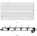
FIG. 3 is a front view of a bottom plate of a battery module with an exhaust hole; -
FIG. 4 is another partial sectional view of a battery device; -
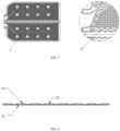
FIG. 5 is a front view of a liquid cooling plate; and -
FIG. 6 is a cross-sectional view of a liquid cooling plate. - Reference numerals:
1: battery module; 2: liquid cooling plate; 21: cover plate of a liquid cooling plate; 22: bottom plate of a liquid cooling plate; 23: flow channel; 3: bottom plate of a housing; 4: beam; 11: cover plate of a battery module; 12: bottom plate of a battery module; 5: housing body; 6: explosion-proof valve; 7: exhaust hole. - The following further describes the present invention with reference to embodiments. It should be understood that the embodiments are merely intended to further describe and explain the present invention, and are not intended to limit the present invention.
- Unless otherwise defined, technical and scientific terms in this specification have the same meanings as those commonly understood by a person skilled in the art. Although methods and materials similar to or the same as those described herein can be used in experimental or practical applications, the materials and methods are still described below in this specification. In the case of a conflict, definitions of the materials and methods included in this specification shall prevail. In addition, the materials, methods, and examples are for illustration only and are not limitative. The following further describes the present invention with reference to specific embodiments, which are not intended to limit the scope of the present invention.
- Unless otherwise specified and defined explicitly, the terms "connected to", "connect", and "fasten" should be understood in a broad sense, for example, may be a fixed connection, may be a detachable connection or an integrated connection; may be a mechanical connection, or may be an electrical connection; and may be a direct connection, may be an indirect connection through an intermediate medium, or may be internal communication between two elements or an interaction relationship between two elements. A person of ordinary skill in the art can understand specific meanings of the above-mentioned terms in the present invention based on an actual situation.
- The present invention provides a battery device, where the battery device includes a housing, a battery module, and a liquid cooling plate; the battery module includes a cover plate and a bottom plate that are opposite to each other, where the cover plate of the battery module is attached to the liquid cooling plate; and the housing is configured to accommodate the battery module, the bottom plate of the battery module is provided with a plurality of exhaust holes, and there is a gap between the bottom plate of the battery module and a bottom of the housing.
- The following describes a specific structure of a battery device according to an embodiment of the present invention with reference to
FIG. 1 to FIG. 4 . - As shown in
FIG. 1 to FIG. 4 , the battery device includes a housing, abattery module 1, and a liquid cooling plate 2; thebattery module 1 includes acover plate 11 of the battery module and abottom plate 12 of the battery module that are opposite to each other, where thecover plate 11 of the battery module is attached to the liquid cooling plate 2. Attachment herein means that thecover plate 11 of the battery module is in direct contact with the liquid cooling plate 2. However, in the conventional battery device, the liquid cooling plate is located at a bottom of the battery module, and the liquid cooling plate needs to be loaded into the housing first, and then the battery module is loaded into the housing, so that the battery module is attached to the liquid cooling plate. Further, the liquid cooling plate 2 in the present invention is located above the cover plate of the battery module, and the liquid cooling plate 2 can be directly connected to a vehicle body, so that the vehicle body protects the liquid cooling plate, thereby enhancing mechanical strength of a top of the battery device. A conventional housing includes a bottom plate of the housing and a cover plate of the housing. Compared with a conventional battery device, in this design of the present invention, the cover plate of the housing may be optionally not disposed in terms of structure, thereby reducing mounting space, reducing a weight of the battery device, and reducing costs. In addition, the liquid cooling plate is disposed above the battery module, and does not need to bear a weight of the module, and is used only for cooling, so that a thickness of the liquid cooling plate can be reduced, and a weight of the battery device can be further reduced. The housing is configured to accommodate thebattery module 1, thebottom plate 12 of the battery module is provided with a plurality of exhaust holes 7, and there is a gap between thebottom plate 12 of the battery module and a bottom of the housing. - The liquid cooling plate 2 in the present invention may be any existing liquid cooling plate in the conventional technology, or may be the liquid cooling plate 2 shown in
FIG. 5 and FIG. 6 . Specifically, as shown inFIG. 5 and FIG. 6 , the liquid cooling plate 2 includes acover plate 21 of the liquid cooling plate and abottom plate 22 of the liquid cooling plate that are opposite to each other, thecover plate 21 of the liquid cooling plate has a plurality of recesses, and thecover plate 21 of the liquid cooling plate is attached to thebottom plate 22 of the liquid cooling plate through the recesses, where the plurality of recesses are arranged in a dot matrix, and are preferably arranged in a staggered manner. The staggered arrangement means that two adjacent rows of recesses are arranged in a staggered manner. A flow channel formed in this staggered arrangement manner ensures that cooling liquid in the flow channel does not flow in a straight line. When the cooling liquid enters the liquid cooling plate 2, the cooling liquid can flow in theflow channel 23 in a direction indicated by an arrow inFIG. 5 , that is, flow in the liquid cooling plate 2 in a staggered manner, thereby providing a better cooling effect. - The
cover plate 21 of the liquid cooling plate and thebottom plate 22 of the liquid cooling plate are two flat plates, and thicknesses of the two flat plates may be the same or different, for example, the thickness of each plate may be 1 mm. Materials of thecover plate 21 of the liquid cooling plate and thebottom plate 22 of the liquid cooling plate may be Al3003 or other Al ofseries 3. The recess of thecover plate 21 of the liquid cooling plate may be a part of a spherical shape or another shape of a recess. After thecover plate 21 of the liquid cooling plate and thebottom plate 22 of the liquid cooling plate are connected through soldering, the recess is attached to thebottom plate 22, and aflow channel 23 connecting a peripheral unrecessed position and thebottom plate 22 of the liquid cooling plate is formed to circulate the cooling liquid. A processing technique of thebottom plate 22 of the liquid cooling plate and thecover plate 21 of the liquid cooling plate may be stamping, harmonica-type processing, or aluminum extrusion. Stamping with a lowest cost is preferably selected for processing and molding. A distance between two adjacent recesses is 15 mm to 20 mm. A depth of theflow channel 23 is 2 mm to 5 mm. The depth herein refers to a distance between thebottom plate 22 of the liquid cooling plate and thecover plate 21 of the liquid cooling plate in thecorresponding flow channel 23. - Optionally, a thickness of the liquid cooling plate 2 is 2 mm to 5 mm. The thickness herein means that a maximum distance between an upper surface of the
cover plate 21 of the liquid cooling plate and a lower surface of thebottom plate 22 of the liquid cooling plate is 2 mm to 5 mm. - The above-mentioned structure of dot-matrix staggered arrangement of a plurality of recesses can achieve an optimal heat exchange effect. When a volume of a flow channel is the same, a simulation manner is used to compare a cooling effect of the dot-matrix staggered arrangement in the present invention with a cooling effect of using an S-shaped flow channel. A result shows that a temperature difference between a highest temperature and a lowest temperature in the structure of the dot-matrix staggered arrangement is 4.4°C, which is less than 4.7°C in the S-shaped flow channel. In addition, a pressure difference between a water inlet and a water outlet of the flow channel for the dot-matrix staggered arrangement is 21 kPa, and a pressure difference for the S-shaped flow channel is 22 kPa. A simulation result shows that the flow channel structure of the dot-matrix staggered arrangement in the present invention has a better cooling effect and a smaller resistance.
- The
battery module 1 further includes structures such as a cell, a busbar, end plates on two sides, and side plates on two sides. The cell can be specifically designed based on an actual need, which is not limited herein. In a specific embodiment, the cell of thebattery module 1 is a pouch cell. The pouch cell has no pressure relief valve and a cell placement manner is flexible and changeable so that cooling can be performed from all directions. Therefore, a top cooling manner can be used. In addition, the battery module and the beam are tightly attached to the liquid cooling plate without a gap, and air content inside the battery device is small and condensate water is not easily generated. Even if a small amount of condensate water is generated on an inner side of the liquid cooling plate during charging, discharging, and cooling, the condensate water does not drip on electrified bodies such as positive and negative terminals of the module. The condensate water may only drip on a sampling plate of the battery module and a connector position of the sampling plate. Because these positions already meet waterproof requirements such as IP65, dripping of a small amount of condensate water drip has no impact on a function and electrical insulation of the battery module. - The
cover plate 11 of the battery module is attached to the liquid cooling plate 2. "Attachment" herein may refer to any manner of fastening, connection, adhesion, and the like in the conventional technology that needs to be used based on a specific design. In a specific embodiment, thecover plate 11 of the battery module is fastened and attached to the liquid cooling plate 2 by using a thermally conductive adhesive, so that heat of the battery module is transferred by using the thermally conductive adhesive. - In a specific embodiment, the
battery module 1 can be pre-tightened and stacked in a sequence of "end plate - cell (there are several cells, and a specific quantity is determined based on a capacity of the battery module) - end plate", and then tabs on two sides of the cell are welded to the busbar. Then, the side plates on two sides are respectively welded to the end plates on two sides, and finally, thecover plate 11 and thebottom plate 12 of the battery module are separately welded. - The housing includes a housing body 5 and a
bottom plate 3 of the housing, and a cavity formed by the housing body 5 and thebottom plate 3 of the housing is used to accommodate thebattery module 1. A shape of the housing can be adjusted based on a structure of thebattery module 1 or a specific design need. In a specific embodiment, abeam 4 is disposed inside the housing, and thebattery module 1 is fastened to thebeam 4. For example, thebattery module 1 can be fastened to thebeam 4 through bolted connection. Thebeam 4 can be designed by using any solution known in the conventional technology, for example, may be a crossbeam, a longitudinal beam, or another type of beam. - As shown in
FIG. 3 , thebottom plate 12 of the battery module is provided with a plurality of exhaust holes 7. When thermal runaway occurs on the cell of thebattery module 1, the exhaust hole 7 is configured to discharge high-temperature gas or flame generated by the cell to the outside of the battery device. A shape, a spacing, a quantity, and the like of exhaust holes 7 are not limited in terms of design, and can be flexibly designed as needed. In a specific embodiment, distribution density of the plurality of exhaust holes 7 on thebottom plate 12 of the battery module is 8%-20%. A value of the distribution density is equal to an area of the plurality of exhaust holes divided by an area of the bottom plate of the battery module. For example, if the area of thebottom plate 12 of the battery module is 1 m2 and the total area of the plurality of exhaust holes 7 is 0.2 m2, the distribution density of the plurality of exhaust holes 7 on thebottom plate 12 of the battery module is 0.2. - The exhaust holes 7 may be in any shape, for example, may be in a circular shape, a kidney shape, an oval shape, a triangular shape, a quadrilateral shape, or another regular or irregular shape. The exhaust holes 7 may be in a same shape, or may be a combination of two or more shapes. In a specific implementation, the exhaust hole is a circle with an aperture of 2 mm to 10 mm.
- In a specific embodiment, the exhaust hole 7 is a combination of a kidney shape and a circular shape. As shown in
FIG. 3 , the kidney-shaped exhaust hole is provided at an edge position of thebottom plate 12 of the battery module, that is, a position away from a center of thebottom plate 12 of the battery module. The circular exhaust hole is provided at a position closer to the center of thebottom plate 12 of the battery module relative to the kidney-shaped exhaust hole, and an area of a single kidney-shaped exhaust hole is larger than an area of a single circular exhaust hole. In a specific implementation, a total area of the kidney-shaped exhaust holes is 15372 mm2 and a total area of the circular exhaust holes is 11290 mm2. According to the simulation and actual measurement results, more than 80% of the gas is discharged from the edge position of thebottom plate 12 of the battery module. Therefore, providing the kidney-shaped exhaust holes with a larger opening area at the edge position of thebottom plate 12 of the battery module is more conducive to gas discharge of the battery module. - Further, a spacing between two adjacent exhaust holes 7 is 8 mm to 15 mm.
- In a specific embodiment, the exhaust hole 7 is sealed by using an insulation film. The insulation film mainly serves to prevent foreign matters from entering the module and improve the electrical insulation performance of the module.
- There is a gap between the
bottom plate 12 of the battery module and the bottom of the housing, which means that there is a gap between thebottom plate 12 and thebottom plate 3 of the housing. The gap between thebottom plate 12 of the battery module and the bottom of the housing is conducive to heat diffusion, so that high-temperature gas or flame generated by the cell is not blocked by the housing, and further discharged from the bottom of the housing, without posing a serious threat to a passenger compartment of a vehicle. To achieve a good heat diffusion effect, preferably, the gap between thebottom plate 12 of the battery module and the bottom of the housing is 2 mm to 20 mm, for example, may be 2 mm, 3 mm, 4 mm, 5 mm, 6 mm, 7 mm, 8 mm, 9 mm, 10 mm, 11 mm, 12 mm, 13 mm, 14 mm, 15 mm, 16 mm, 17 mm, 18 mm, 19 mm, or 20 mm. Specifically, the gap between thebottom plate 12 of the battery module and the bottom of the housing refers to a distance between thebottom plate 12 of the battery module and thebottom plate 3 of the housing. - In a specific embodiment, an explosion-
proof valve 6 is disposed at the bottom of the housing, that is, an explosion-proof valve is disposed on thebottom plate 3 of the housing, and is configured to discharge the high-temperature gas or flame generated by the cell to the outside of the battery device through the exhaust hole 7 and the explosion-proof valve 6 successively. A structure of the explosion-proof valve 6 may be an explosion-proof valve structure known in the conventional technology, and a quantity of the explosion-proof valve 6 may be adjusted based on an actual need. In a specific embodiment, there are four explosion-proof valves 6. The explosion-proof valve 6 may alternatively be replaced with another similar product of a film type or a mesh shape, provided that a gas discharge function can be implemented. - Further, the battery device further includes a battery management system and a battery protection apparatus.
- The present invention further provides a method for assembling the above-mentioned battery device. The method includes the following steps: fastening a liquid cooling plate to a housing body and performing upside-down flipping by 180 degrees; fastening a battery module inside the housing body, so that a cover plate of the battery module is attached to the liquid cooling plate; and fastening a bottom plate of a housing to the housing body and performing upside-down flipping by 180 degrees to obtain the battery device.
- Further, the method further includes connecting the obtained battery device to a vehicle.
- Specifically, the battery device in the present invention can be assembled in the following manner:
First, the liquid cooling plate and the housing body are fastened by using a structural adhesive and/or a bolt, and then flipped upside down by 180 degrees after the fastening (in this case, the liquid cooling plate is located at the bottom). Then, the battery module is placed into the housing body. The battery module is not fastened to the bottom plate of the housing in a conventional manner. Instead, the module is flipped upside down by 180 degrees and then flanges on two sides of the battery module are fastened, through bolted connection, to beams that are connected to two ends of the housing. The battery module is connected to the liquid cooling plate by using a thermally conductive adhesive. Finally, the bottom plate of the housing is fastened to the housing body by using a structural adhesive and bolted connection. In this case, the assembled battery device is flipped upside down by 180 degrees again (in this case, the liquid cooling plate is located at the top and the bottom plate of the housing is located at the bottom), and can be further connected to a vehicle. Inside the battery device, heat transfer is performed between the top of the battery module and the liquid cooling plate by using a thermally conductive adhesive. In the middle, the flange of the module is hung on the beam of the housing through bolted connection. There is a gap of 2 mm to 20 mm between the bottom of the battery module and the bottom of the housing. - As shown in
FIG. 1 to FIG. 4 , a battery device includes a housing, abattery module 1, and a liquid cooling plate 2; thebattery module 1 includes acover plate 11 of the battery module and abottom plate 12 of the battery module that are opposite to each other, where thecover plate 11 of the battery module is fastened and attached to the liquid cooling plate 2 by using a thermally conductive adhesive; and the housing is configured to accommodate thebattery module 1, and four explosion-proof valves are disposed at the bottom of the housing, that is, on thebottom plate 3 of the housing. Acrossbeam 4 is disposed inside the housing, and thebattery module 1 is fastened to thecrossbeam 4 through bolted connection. A cell in thebattery module 1 is a pouch cell. - An area of the
bottom plate 12 of the battery module is 180588 mm2, 648 exhaust holes 7 are disposed, and each exhaust hole 7 is sealed by using an insulation film. The exhaust hole 7 is a combination of a kidney shape and a circular shape. As shown inFIG. 3 , the kidney-shaped exhaust hole is provided at an edge position of thebottom plate 12 of the battery module, the circular exhaust hole is provided at a position closer to the center of thebottom plate 12 of the battery module relative to the kidney-shaped exhaust hole, an area of a single kidney-shaped exhaust hole is 213.5 mm2, and an area of a single circular exhaust hole is 19.6 mm2. A total area of the kidney-shaped exhaust holes is 15372 mm2, a total area of the circular exhaust holes is 11290 mm2, a distance between two adjacent exhaust holes is 11.4 mm, and distribution density of the plurality of exhaust holes 7 on thebottom plate 12 of the battery module is 14.8%. There is a gap between thebottom plate 12 of the battery module and the bottom of the housing, and the gap is 10 mm, that is, a distance between thebottom plate 12 of the battery module and thebottom plate 3 of the housing is 10 mm. - As shown in
FIG. 5 and FIG. 6 , the liquid cooling plate 2 includes acover plate 21 of the liquid cooling plate and abottom plate 22 of the liquid cooling plate that are opposite to each other, thecover plate 21 of the liquid cooling plate has a plurality of recesses, and thecover plate 21 of the liquid cooling plate is attached to thebottom plate 22 of the liquid cooling plate through the recesses, where the plurality of recesses are arranged in a dot matrix in a staggered manner. Thecover plate 21 of the liquid cooling plate and thebottom plate 22 of the liquid cooling plate are two flat plates with a thickness of 1 mm and a material of Al3003. The recess of thecover plate 21 of the liquid cooling plate is a part of a spherical shape. After thecover plate 21 of the liquid cooling plate and thebottom plate 22 of the liquid cooling plate are connected through soldering, the recess is attached to thebottom plate 22, and aflow channel 23 connecting a peripheral unrecessed position and thebottom plate 22 of the liquid cooling plate is formed to circulate the cooling liquid. A distance between two adjacent recesses is 18 mm. A depth of theflow channel 23 is 3 mm. A thickness of the liquid cooling plate 2 is 5 mm. - A battery device in Embodiment 2 has a same structure as the battery device in
Embodiment 1, and a difference lies only in a distance between abottom plate 12 of a battery module and abottom plate 3 of a housing. An area of thebottom plate 12 of the battery module is 180588 mm2, 648 exhaust holes 7 are disposed, and each exhaust hole 7 is sealed by using an insulation film. The exhaust hole 7 is a combination of a kidney shape and a circular shape. As shown inFIG. 3 , the kidney-shaped exhaust hole is provided at an edge position of thebottom plate 12 of the battery module, the circular exhaust hole is provided at a position closer to the center of thebottom plate 12 of the battery module relative to the kidney-shaped exhaust hole, an area of a single kidney-shaped exhaust hole is 213.5 mm2, and an area of a single circular exhaust hole is 19.6 mm2. A total area of the kidney-shaped exhaust holes is 15372 mm2, a total area of the circular exhaust holes is 11290 mm2, a distance between two adjacent exhaust holes is 11.4 mm, and distribution density of the plurality of exhaust holes 7 on thebottom plate 12 of the battery module is 14.8%. There is a gap between thebottom plate 12 of the battery module and the bottom of the housing, and the gap is 2 mm, that is, a distance between thebottom plate 12 of the battery module and thebottom plate 3 of the housing is 2 mm. - The liquid cooling plate 2 is the same as that in
Embodiment 1. -
Embodiment 3 differs fromEmbodiment 1 in a distance between abottom plate 12 of a battery module and abottom plate 3 of a housing. An area of thebottom plate 12 of the battery module is 180588 mm2, 648 exhaust holes 7 are disposed, and each exhaust hole 7 is sealed by using an insulation film. The exhaust hole 7 is a combination of a kidney shape and a circular shape. As shown inFIG. 3 , the kidney-shaped exhaust hole is provided at an edge position of thebottom plate 12 of the battery module, the circular exhaust hole is provided at a position closer to the center of thebottom plate 12 of the battery module relative to the kidney-shaped exhaust hole, an area of a single kidney-shaped exhaust hole is 213.5 mm2, and an area of a single circular exhaust hole is 19.6 mm2. A total area of the kidney-shaped exhaust holes is 15372 mm2, a total area of the circular exhaust holes is 11290 mm2, a distance between two adjacent exhaust holes is 11.4 mm, and distribution density of the plurality of exhaust holes 7 on thebottom plate 12 of the battery module is 14.8%. There is a gap between thebottom plate 12 of the battery module and the bottom of the housing, and the gap is 20 mm, that is, a distance between thebottom plate 12 of the battery module and thebottom plate 3 of the housing is 20 mm. - The liquid cooling plate 2 is the same as that in
Embodiment 1. -
Embodiment 4 differs fromEmbodiment 1 in a design of abottom plate 12 of a battery module. - An area of the
bottom plate 12 of the battery module is 180588 mm2, and circular exhaust holes 7 are evenly provided on thebottom plate 12 of the battery module, where an area of a single circular exhaust hole is 19.6 mm2, and each exhaust hole 7 is sealed by using an insulation film. A total area of the circular exhaust holes 7 is 26662 mm2, and distribution density of the plurality of exhaust holes 7 on thebottom plate 12 of the battery module is 14.8%. There is a gap between thebottom plate 12 of the battery module and the bottom of the housing, and the gap is 10 mm, that is, a distance between thebottom plate 12 of the battery module and thebottom plate 3 of the housing is 10 mm. The liquid cooling plate 2 is the same as that inEmbodiment 1. - Embodiment 5 differs from
Embodiment 1 in a design of abottom plate 12 of a battery module. - An area of the
bottom plate 12 of the battery module is 180588 mm2, and kidney-shaped exhaust holes 7 are evenly provided on thebottom plate 12 of the battery module, where an area of a single kidney-shaped exhaust hole is 213.5 mm2, and each exhaust hole 7 is sealed by using an insulation film. A total area of the kidney-shaped exhaust holes 7 is 26662 mm2, and distribution density of the plurality of exhaust holes 7 on thebottom plate 12 of the battery module is 14.8%. There is a gap between thebottom plate 12 of the battery module and the bottom of the housing, and the gap is 10 mm, that is, a distance between thebottom plate 12 of the battery module and thebottom plate 3 of the housing is 10 mm. The liquid cooling plate 2 is the same as that inEmbodiment 1. - A thermal runaway test is performed on the battery device in
Embodiment 1 to Embodiment 5. A specific test method is as follows: - The test is performed by triggering, by using a heating method, a cell at a middle position of the battery to undergo thermal runaway. For details, refer to the national power battery standards (
GB 38031-2020 Embodiment 1 to Embodiment 5 of the present invention is triggered to undergo thermal runaway without adding any fire protection and heat insulation material such as a mica sheet or an aerogel to the battery device. No fire or explosion occurs outside the battery pack within five minutes for all embodiments. This surpasses the standard required in theGB 38031-2020 Embodiment 1 and Embodiment 5 exceeds one hour. However, Embodiment 5 uses a design in which all holes are kidney-shaped holes, and a simulation result shows that mechanical structure strength in Embodiment 5 is relatively low, and Embodiment 5 may fail an extrusion test. Therefore,Embodiment 1 is an optimal design.Table 1 Duration within which naked flame appears outside the housing after thermal runaway is triggered Embodiment 1More than one hour Embodiment 2 8 minutes Embodiment 3 30 minutes Embodiment 4 10 minutes Embodiment 5 More than one hour
Claims (19)
- A battery device, whereinthe battery device comprises a housing, a battery module, and a liquid cooling plate;the battery module comprises a cover plate and a bottom plate that are opposite to each other, wherein the cover plate of the battery module is attached to the liquid cooling plate; andthe housing is configured to accommodate the battery module, the bottom plate of the battery module is provided with a plurality of exhaust holes, and there is a gap between the bottom plate of the battery module and a bottom of the housing.
- The battery device according to claim 1,wherein a beam is disposed inside the housing and the battery module is fastened to the beam.
- The battery device according to claim 1, wherein an explosion-proof valve is disposed at the bottom of the housing.
- The battery device according to claim 1, wherein distribution density of the plurality of exhaust holes on the bottom plate of the battery module is 8%-20%, wherein a value of the distribution density is equal to an area of the plurality of exhaust holes divided by an area of the bottom plate of the battery module.
- The battery device according to claim 1, wherein an aperture of the exhaust hole is 2 mm to 10 mm.
- The battery device according to claim 5, wherein a spacing between adjacent exhaust holes is 8 mm to 15 mm.
- The battery device according to claim 1, wherein an area of a single exhaust hole disposed at an edge of the bottom plate of the battery module is larger than an area of a single exhaust hole disposed at a center of the bottom plate of the battery module.
- The battery device according to claim 1, wherein the exhaust hole is sealed by using an insulation film.
- The battery device according to claim 1, wherein the gap between the bottom plate of the battery module and the bottom of the housing is 2 mm to 20 mm.
- The battery device according to claim 1, wherein the battery module comprises a pouch cell.
- The battery device according to claim 1, wherein the liquid cooling plate comprises a cover plate of the liquid cooling plate and a bottom plate of the liquid cooling plate that are opposite to each other, the cover plate of the liquid cooling plate has a plurality of recesses, and the cover plate of the liquid cooling plate is attached to the bottom plate of the liquid cooling plate through the recesses, wherein the plurality of recesses are arranged in a dot matrix, and are preferably arranged in a staggered manner.
- The battery device according to claim 11, wherein a distance between adjacent recesses is 15 mm to 20 mm.
- The battery device according to claim 11, wherein a depth of a flow channel of the liquid cooling plate is 2 mm to 5 mm.
- The battery device according to claim 11, wherein a thickness of the liquid cooling plate is 2 mm to 5 mm.
- The battery device according to claim 1, wherein the housing is not provided with a cover plate.
- A liquid cooling plate, wherein the liquid cooling plate comprises a cover plate of the liquid cooling plate and a bottom plate of the liquid cooling plate that are opposite to each other, the cover plate of the liquid cooling plate has a plurality of recesses, and the cover plate of the liquid cooling plate is attached to the bottom plate of the liquid cooling plate through the recesses, wherein the plurality of recesses are arranged in a dot matrix, and are preferably arranged in a staggered manner.
- The liquid cooling plate according to claim 16, wherein a distance between adjacent recesses is 15 mm to 20 mm.
- The liquid cooling plate according to claim 16, wherein a depth of a flow channel of the liquid cooling plate is 2 mm to 5 mm.
- The liquid cooling plate according to claim 16, wherein a thickness of the liquid cooling plate is 2 mm to 5 mm.
Applications Claiming Priority (2)
| Application Number | Priority Date | Filing Date | Title |
|---|---|---|---|
| CN202110806950.3A CN114709551B (en) | 2021-07-16 | 2021-07-16 | Battery equipment and preparation method thereof |
| PCT/CN2021/122069 WO2023284133A1 (en) | 2021-07-16 | 2021-09-30 | Battery device and preparation method therefor |
Publications (1)
| Publication Number | Publication Date |
|---|---|
| EP4372891A1 true EP4372891A1 (en) | 2024-05-22 |
Family
ID=82167102
Family Applications (1)
| Application Number | Title | Priority Date | Filing Date |
|---|---|---|---|
| EP21949906.8A Withdrawn EP4372891A1 (en) | 2021-07-16 | 2021-09-30 | Battery device and preparation method therefor |
Country Status (3)
| Country | Link |
|---|---|
| EP (1) | EP4372891A1 (en) |
| CN (1) | CN114709551B (en) |
| WO (1) | WO2023284133A1 (en) |
Families Citing this family (2)
| Publication number | Priority date | Publication date | Assignee | Title |
|---|---|---|---|---|
| CN218632348U (en) * | 2022-11-22 | 2023-03-14 | 浙江极氪智能科技有限公司 | Battery package and car |
| CN223193848U (en) * | 2024-08-16 | 2025-08-05 | 惠州亿纬锂能股份有限公司 | Battery system and vehicle |
Family Cites Families (25)
| Publication number | Priority date | Publication date | Assignee | Title |
|---|---|---|---|---|
| JP2007027011A (en) * | 2005-07-20 | 2007-02-01 | Sanyo Electric Co Ltd | Power supply |
| JP6299513B2 (en) * | 2014-07-31 | 2018-03-28 | 株式会社Gsユアサ | Power pack |
| JP6540435B2 (en) * | 2015-09-30 | 2019-07-10 | 株式会社Gsユアサ | Power storage device |
| CN205863274U (en) * | 2015-12-11 | 2017-01-04 | 庄新国 | A kind of Li-ion batteries piles deflector |
| CN207199692U (en) * | 2017-06-19 | 2018-04-06 | 创科(澳门离岸商业服务)有限公司 | Rechargeable battery pack |
| CN107565190A (en) * | 2017-08-25 | 2018-01-09 | 上海电气集团股份有限公司 | Battery modules cooling system and battery bag |
| CN109786885B (en) * | 2017-11-15 | 2020-12-04 | 宁德时代新能源科技股份有限公司 | Battery module |
| CN208655840U (en) * | 2018-08-02 | 2019-03-26 | 欣旺达电动汽车电池有限公司 | A kind of liquid cooling plate |
| CN208622789U (en) * | 2018-08-26 | 2019-03-19 | 杭州捷能科技有限公司 | A kind of lightweight high-efficiency battery packet |
| JP7235485B2 (en) * | 2018-11-27 | 2023-03-08 | 株式会社エンビジョンAescジャパン | BATTERY CASE, VEHICLE INCLUDING THE SAME, AND STATIONAL POWER STORAGE DEVICE |
| CN208939115U (en) * | 2018-11-28 | 2019-06-04 | 深圳市品诺能源有限公司 | A lithium battery with uniform heat dissipation in all directions |
| CN111106277B (en) * | 2018-12-29 | 2021-05-07 | 宁德时代新能源科技股份有限公司 | Battery pack |
| CN209658367U (en) * | 2019-03-06 | 2019-11-19 | 肇庆遨优动力电池有限公司 | Battery pack structure |
| KR102085750B1 (en) * | 2019-04-01 | 2020-03-06 | (주)엠에스티이 | Battery cell assembly |
| WO2021008541A1 (en) * | 2019-07-17 | 2021-01-21 | 威睿电动汽车技术(宁波)有限公司 | Battery pack cooling system and vehicle |
| CN112303308B (en) * | 2019-08-23 | 2021-10-22 | 宁德时代新能源科技股份有限公司 | Explosion-proof valve, battery pack and electric vehicle |
| US11728541B2 (en) * | 2019-09-05 | 2023-08-15 | Samsung Sdi Co., Ltd. | Energy storage module |
| EP3823082B1 (en) * | 2019-10-03 | 2023-07-19 | Honda Motor Co., Ltd. | Battery module, electric power unit, and work machine |
| CN210897471U (en) * | 2019-12-24 | 2020-06-30 | 孚能科技(镇江)有限公司 | Battery module housing and battery module |
| CN211879451U (en) * | 2020-04-28 | 2020-11-06 | 北京新能源汽车股份有限公司 | Battery bracket for battery pack, battery pack and vehicle |
| CN211743350U (en) * | 2020-04-28 | 2020-10-23 | 上海比耐信息科技有限公司 | Battery pack |
| CN212366138U (en) * | 2020-06-18 | 2021-01-15 | 恒大新能源技术(深圳)有限公司 | Power battery package and electric automobile |
| CN212461820U (en) * | 2020-07-28 | 2021-02-02 | 马鞍山纳百川热交换器有限公司 | Liquid cooling plate integrated on battery pack box |
| CN213362540U (en) * | 2020-10-14 | 2021-06-04 | 杭州孚能能源科技有限公司 | High-low temperature two-section plate type air preheater |
| CN113097639A (en) * | 2021-03-31 | 2021-07-09 | 珠海冠宇动力电池有限公司 | a battery pack |
-
2021
- 2021-07-16 CN CN202110806950.3A patent/CN114709551B/en active Active
- 2021-09-30 WO PCT/CN2021/122069 patent/WO2023284133A1/en not_active Ceased
- 2021-09-30 EP EP21949906.8A patent/EP4372891A1/en not_active Withdrawn
Also Published As
| Publication number | Publication date |
|---|---|
| CN114709551A (en) | 2022-07-05 |
| WO2023284133A1 (en) | 2023-01-19 |
| CN114709551B (en) | 2023-09-26 |
Similar Documents
| Publication | Publication Date | Title |
|---|---|---|
| CN216529223U (en) | a battery pack | |
| EP2619836B1 (en) | Lithium accumulator | |
| CN117080667B (en) | Battery box and battery pack | |
| WO2023072224A1 (en) | Cylindrical cell module | |
| WO2011145830A2 (en) | Compact cooling member having superior stability, and battery module comprising same | |
| CN215816252U (en) | Battery system | |
| CN116799413B (en) | Battery pack | |
| CN219226400U (en) | Battery and power utilization device with same | |
| CN110890605A (en) | A double-sided tapered liquid-cooling plate that can work on both sides | |
| US20240088513A1 (en) | Battery Pack | |
| CN114709551B (en) | Battery equipment and preparation method thereof | |
| US20250309466A1 (en) | Pressure relief structure for double-layer battery and battery pack | |
| CN113036276A (en) | Battery pack and electric vehicle | |
| JP7841130B2 (en) | Battery pack | |
| EP4261982A1 (en) | Lithium ion secondary battery and electric vehicle | |
| CN220492056U (en) | battery pack | |
| CN117810598A (en) | Heat exchange device and battery system | |
| CN212257515U (en) | Electric core isolation device of power battery pack of portable battery-replacing electric vehicle and power battery pack | |
| CN223079293U (en) | Battery Pack | |
| CN219610561U (en) | Battery box and battery pack | |
| CN219892287U (en) | Battery module cooling system | |
| CN221201418U (en) | Battery pack and electric equipment thereof | |
| CN223693195U (en) | Battery pack and electricity utilization device | |
| CN220306442U (en) | Battery pack and electrical devices using it | |
| JP7858132B2 (en) | Battery pack |
Legal Events
| Date | Code | Title | Description |
|---|---|---|---|
| STAA | Information on the status of an ep patent application or granted ep patent |
Free format text: STATUS: THE INTERNATIONAL PUBLICATION HAS BEEN MADE |
|
| PUAI | Public reference made under article 153(3) epc to a published international application that has entered the european phase |
Free format text: ORIGINAL CODE: 0009012 |
|
| STAA | Information on the status of an ep patent application or granted ep patent |
Free format text: STATUS: REQUEST FOR EXAMINATION WAS MADE |
|
| 17P | Request for examination filed |
Effective date: 20240129 |
|
| AK | Designated contracting states |
Kind code of ref document: A1 Designated state(s): AL AT BE BG CH CY CZ DE DK EE ES FI FR GB GR HR HU IE IS IT LI LT LU LV MC MK MT NL NO PL PT RO RS SE SI SK SM TR |
|
| DAV | Request for validation of the european patent (deleted) | ||
| DAX | Request for extension of the european patent (deleted) | ||
| STAA | Information on the status of an ep patent application or granted ep patent |
Free format text: STATUS: THE APPLICATION IS DEEMED TO BE WITHDRAWN |
|
| 18D | Application deemed to be withdrawn |
Effective date: 20250401 |