EP4372889A1 - Battery pack - Google Patents
Battery pack Download PDFInfo
- Publication number
- EP4372889A1 EP4372889A1 EP23816394.3A EP23816394A EP4372889A1 EP 4372889 A1 EP4372889 A1 EP 4372889A1 EP 23816394 A EP23816394 A EP 23816394A EP 4372889 A1 EP4372889 A1 EP 4372889A1
- Authority
- EP
- European Patent Office
- Prior art keywords
- partition member
- wall
- battery pack
- ribs
- supplementary
- Prior art date
- Legal status (The legal status is an assumption and is not a legal conclusion. Google has not performed a legal analysis and makes no representation as to the accuracy of the status listed.)
- Granted
Links
Images




Classifications
-
- H—ELECTRICITY
- H01—ELECTRIC ELEMENTS
- H01M—PROCESSES OR MEANS, e.g. BATTERIES, FOR THE DIRECT CONVERSION OF CHEMICAL ENERGY INTO ELECTRICAL ENERGY
- H01M50/00—Constructional details or processes of manufacture of the non-active parts of electrochemical cells other than fuel cells, e.g. hybrid cells
- H01M50/30—Arrangements for facilitating escape of gases
- H01M50/35—Gas exhaust passages comprising elongated, tortuous or labyrinth-shaped exhaust passages
- H01M50/367—Internal gas exhaust passages forming part of the battery cover or case; Double cover vent systems
-
- H—ELECTRICITY
- H01—ELECTRIC ELEMENTS
- H01M—PROCESSES OR MEANS, e.g. BATTERIES, FOR THE DIRECT CONVERSION OF CHEMICAL ENERGY INTO ELECTRICAL ENERGY
- H01M50/00—Constructional details or processes of manufacture of the non-active parts of electrochemical cells other than fuel cells, e.g. hybrid cells
- H01M50/30—Arrangements for facilitating escape of gases
- H01M50/35—Gas exhaust passages comprising elongated, tortuous or labyrinth-shaped exhaust passages
- H01M50/358—External gas exhaust passages located on the battery cover or case
-
- H—ELECTRICITY
- H01—ELECTRIC ELEMENTS
- H01M—PROCESSES OR MEANS, e.g. BATTERIES, FOR THE DIRECT CONVERSION OF CHEMICAL ENERGY INTO ELECTRICAL ENERGY
- H01M10/00—Secondary cells; Manufacture thereof
- H01M10/60—Heating or cooling; Temperature control
- H01M10/61—Types of temperature control
- H01M10/613—Cooling or keeping cold
-
- H—ELECTRICITY
- H01—ELECTRIC ELEMENTS
- H01M—PROCESSES OR MEANS, e.g. BATTERIES, FOR THE DIRECT CONVERSION OF CHEMICAL ENERGY INTO ELECTRICAL ENERGY
- H01M10/00—Secondary cells; Manufacture thereof
- H01M10/60—Heating or cooling; Temperature control
- H01M10/62—Heating or cooling; Temperature control specially adapted for specific applications
- H01M10/625—Vehicles
-
- H—ELECTRICITY
- H01—ELECTRIC ELEMENTS
- H01M—PROCESSES OR MEANS, e.g. BATTERIES, FOR THE DIRECT CONVERSION OF CHEMICAL ENERGY INTO ELECTRICAL ENERGY
- H01M50/00—Constructional details or processes of manufacture of the non-active parts of electrochemical cells other than fuel cells, e.g. hybrid cells
- H01M50/20—Mountings; Secondary casings or frames; Racks, modules or packs; Suspension devices; Shock absorbers; Transport or carrying devices; Holders
- H01M50/204—Racks, modules or packs for multiple batteries or multiple cells
-
- H—ELECTRICITY
- H01—ELECTRIC ELEMENTS
- H01M—PROCESSES OR MEANS, e.g. BATTERIES, FOR THE DIRECT CONVERSION OF CHEMICAL ENERGY INTO ELECTRICAL ENERGY
- H01M50/00—Constructional details or processes of manufacture of the non-active parts of electrochemical cells other than fuel cells, e.g. hybrid cells
- H01M50/20—Mountings; Secondary casings or frames; Racks, modules or packs; Suspension devices; Shock absorbers; Transport or carrying devices; Holders
- H01M50/204—Racks, modules or packs for multiple batteries or multiple cells
- H01M50/207—Racks, modules or packs for multiple batteries or multiple cells characterised by their shape
- H01M50/209—Racks, modules or packs for multiple batteries or multiple cells characterised by their shape adapted for prismatic or rectangular cells
-
- H—ELECTRICITY
- H01—ELECTRIC ELEMENTS
- H01M—PROCESSES OR MEANS, e.g. BATTERIES, FOR THE DIRECT CONVERSION OF CHEMICAL ENERGY INTO ELECTRICAL ENERGY
- H01M50/00—Constructional details or processes of manufacture of the non-active parts of electrochemical cells other than fuel cells, e.g. hybrid cells
- H01M50/20—Mountings; Secondary casings or frames; Racks, modules or packs; Suspension devices; Shock absorbers; Transport or carrying devices; Holders
- H01M50/233—Mountings; Secondary casings or frames; Racks, modules or packs; Suspension devices; Shock absorbers; Transport or carrying devices; Holders characterised by physical properties of casings or racks, e.g. dimensions
- H01M50/24—Mountings; Secondary casings or frames; Racks, modules or packs; Suspension devices; Shock absorbers; Transport or carrying devices; Holders characterised by physical properties of casings or racks, e.g. dimensions adapted for protecting batteries from their environment, e.g. from corrosion
-
- H—ELECTRICITY
- H01—ELECTRIC ELEMENTS
- H01M—PROCESSES OR MEANS, e.g. BATTERIES, FOR THE DIRECT CONVERSION OF CHEMICAL ENERGY INTO ELECTRICAL ENERGY
- H01M50/00—Constructional details or processes of manufacture of the non-active parts of electrochemical cells other than fuel cells, e.g. hybrid cells
- H01M50/20—Mountings; Secondary casings or frames; Racks, modules or packs; Suspension devices; Shock absorbers; Transport or carrying devices; Holders
- H01M50/244—Secondary casings; Racks; Suspension devices; Carrying devices; Holders characterised by their mounting method
-
- H—ELECTRICITY
- H01—ELECTRIC ELEMENTS
- H01M—PROCESSES OR MEANS, e.g. BATTERIES, FOR THE DIRECT CONVERSION OF CHEMICAL ENERGY INTO ELECTRICAL ENERGY
- H01M50/00—Constructional details or processes of manufacture of the non-active parts of electrochemical cells other than fuel cells, e.g. hybrid cells
- H01M50/20—Mountings; Secondary casings or frames; Racks, modules or packs; Suspension devices; Shock absorbers; Transport or carrying devices; Holders
- H01M50/289—Mountings; Secondary casings or frames; Racks, modules or packs; Suspension devices; Shock absorbers; Transport or carrying devices; Holders characterised by spacing elements or positioning means within frames, racks or packs
-
- H—ELECTRICITY
- H01—ELECTRIC ELEMENTS
- H01M—PROCESSES OR MEANS, e.g. BATTERIES, FOR THE DIRECT CONVERSION OF CHEMICAL ENERGY INTO ELECTRICAL ENERGY
- H01M50/00—Constructional details or processes of manufacture of the non-active parts of electrochemical cells other than fuel cells, e.g. hybrid cells
- H01M50/20—Mountings; Secondary casings or frames; Racks, modules or packs; Suspension devices; Shock absorbers; Transport or carrying devices; Holders
- H01M50/289—Mountings; Secondary casings or frames; Racks, modules or packs; Suspension devices; Shock absorbers; Transport or carrying devices; Holders characterised by spacing elements or positioning means within frames, racks or packs
- H01M50/291—Mountings; Secondary casings or frames; Racks, modules or packs; Suspension devices; Shock absorbers; Transport or carrying devices; Holders characterised by spacing elements or positioning means within frames, racks or packs characterised by their shape
-
- Y—GENERAL TAGGING OF NEW TECHNOLOGICAL DEVELOPMENTS; GENERAL TAGGING OF CROSS-SECTIONAL TECHNOLOGIES SPANNING OVER SEVERAL SECTIONS OF THE IPC; TECHNICAL SUBJECTS COVERED BY FORMER USPC CROSS-REFERENCE ART COLLECTIONS [XRACs] AND DIGESTS
- Y02—TECHNOLOGIES OR APPLICATIONS FOR MITIGATION OR ADAPTATION AGAINST CLIMATE CHANGE
- Y02E—REDUCTION OF GREENHOUSE GAS [GHG] EMISSIONS, RELATED TO ENERGY GENERATION, TRANSMISSION OR DISTRIBUTION
- Y02E60/00—Enabling technologies; Technologies with a potential or indirect contribution to GHG emissions mitigation
- Y02E60/10—Energy storage using batteries
Definitions
- the present invention relates to a battery pack. More particularly, the battery pack of the present invention is characterized in that it contains a plurality of cell stacks each of which containing one or more battery cells and is capable of releasing high temperature gases generated internally to the exterior by using a supplementary wall that separates each cell stack and includes a gas flow path therein.
- Types of secondary batteries include lithium-ion cells, lithium polymer cells, nickelcadmium cells, nickel-hydrogen cells, nickel-zinc cells, etc.
- These unit secondary battery cells i.e. unit battery cells, have an operating voltage of about 2.5 V to 4.2 V. Therefore, if a higher output voltage is required, a plurality of battery cells may be connected in series to form a battery pack. In addition, depending on the charge and discharge capacity required for the battery pack, a plurality of battery cells may be connected in parallel to form a battery pack. Thus, the number of battery cells included in the battery pack may be varied depending on the required output voltage or charge/discharge capacity.
- a battery pack by connecting a plurality of battery cells in series/parallel, it is common to first form a cell stack of the plurality of battery cells, and then add other components to form a battery pack using the cell stack.
- Cell stack refers to a component with a plurality of secondary batteries connected in series or parallel
- battery pack refers to a component with a plurality of cell stacks connected in series or parallel to increase capacity, power output, etc.
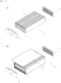
- FIG. 1(a) is an exploded perspective view of a typical cell stack mounted in a battery pack.
- a busbar frame and end plates are coupled to the front and rear of the cell stack, respectively, formed by stacking a plurality of battery cells.
- the cell stack may also be enclosed and protected by a U-shaped module frame or the like, as shown in FIG. 1(b) .
- the battery pack it is important for the battery pack to release the high temperature gases generated by each cell stack effectively. If the high temperature gases generated during the charging and discharging process are not effectively released, heat accumulation will occur, which will accelerate the degradation of the cell stack, and in some cases, ignition or explosion may occur. In addition, the heat of the gases can be transferred to other normally operating cell stacks, resulting in the degradation or explosion of the entire battery cells contained within the battery pack.
- the present invention is directed to solving the above mentioned problems, and aims to provide a battery pack capable of rapidly venting high temperature gases to the outside when degradation occurs in a cell stack of any one of the plurality of cell stacks, to prevent the battery pack from igniting or exploding.
- a battery pack containing a cell stack including one or more battery cells including a pack case having a space in which the cell stack is placed, the pack case including: a base plate supporting a lower portion of the cell stack; a main wall extending across the base plate and coupled to a center portion of the base plate; a side wall having a hollow shape and including a gas venting path therein, and coupled along a periphery of an edge of the base plate; and a plurality of supplementary wall having a front end coupled to the main wall, and a rear end coupled to the side walls, wherein the supplementary wall includes a first partition member including a pair of ribs formed to extend along a longitudinal direction of the supplementary wall, and a second partition member coupled to the first partition member, and wherein at least one of the first partition member and the second partition member includes a first hole between the pair of ribs.
- the supplementary wall may be arranged to be separately spaced along the longitudinal direction of the main wall on both sides of the main wall.
- the pair of ribs may be separately spaced up and down by a predetermined distance.
- the second partition member may be coupled with the first partition member in a direction facing the ribs of the first partition member.
- the supplementary wall may include a plurality of the first holes on one side.
- the first partition member may be penetrated at the rear end to open a space between the pair of ribs in a rearward direction of the first partition member.
- the supplementary wall may be inserted at its rear end into the side wall to allow the opening to be in communicating with the gas venting path.
- the supplementary wall may include a gas flow path closed on its upper and lower surfaces by the pair of ribs, and closed on both sides by the first partition member and the second partition member, the gas flow path being open to the outside through the first hole and the opening, respectively.
- the second partition member may include a pair of ribs formed extending along a longitudinal direction on one side, and the supplementary wall may include a second hole penetrating between the ribs included in the second partition member on the other side opposite to the side in which the first hole is formed.
- the ribs of the second partition member may be formed to not overlapping with the ribs formed on the first partition member.
- the ribs of the second partition member are formed to be located on top of a pair of ribs formed on this first partition member, and the first and second holes may be formed on both sides of the supplementary wall at a lower and upper portion, respectively.
- the first partition member and the second partition member may be penetrated at the rear end to open a space between the pair of ribs in a rearward direction of each partition member.
- the supplementary wall may be inserted at its rear end into the side wall to allow the upper opening and the lower opening to be in communication with the gas venting path.
- the supplementary wall may include a plurality of the first hole and the second hole on each side.
- the supplementary wall including an upper gas flow path located at the top, closed on its upper and lower sides by a pair of ribs formed in the second partition member, and closed on both sides by the first partition member and the second partition member, and a lower gas flow path located at the bottom, closed on its upper and lower sides by a pair of ribs formed in the first partition member and closed on both sides by the first partition member and the second partition member, and the upper gas flow path and the lower gas flow path may not be in communication with each other within the supplementary wall.
- the present invention it is possible to prevent the battery pack from igniting or exploding even if degradation or high temperature gases are generated in the cell stack contained in the battery pack.
- a plurality of a rib shape can be applied to a wall installed within the battery pack and separating each cell stack to improve rigidity while forming a pathway for gas transfer.
- the present invention relates to a battery pack having a structure capable of separating a space in which a plurality of cell stacks is contained, and at the same time, in the event of high temperature gases being generated in any one of the cell stacks, rapidly releasing the gases to the outside.
- the cell stack may be in the form of one or more battery cells stacked, as shown in Figure 1(a) , or in the form of a battery module enclosed by a module frame around its perimeter, as shown in Figure 1(b) .
- a battery pack of the present invention includes a pack case (1000) that provides a space in which a cell stack is located.
- FIG. 2 is a perspective view of the pack case 1000 of the present invention.
- the pack case 1000 includes a base plate 100, a main wall 200, side walls 300, and a supplementary wall 400, as shown in the FIG. 2 .
- the battery pack of the present invention may further include a top cover (not shown).
- the top cover may be combined with the pack case 1000 to form a single housing that contains a plurality of cell stacks.
- the base plate 100 is positioned at a lower portion of the battery pack, in a configuration wherein the cell stack is settled, and supports a lower portion of the cell stack.
- the main wall 200 is formed to extend across the base plate 100 and is coupled to the center of the base plate 100.
- This main wall 200 divides the space inside the pack case 1000 into two main sections so that cell stacks on both sides settle on the base plate 100 symmetrically with respect to each other relative to the main wall 200. In other words, cell stacks located on one side of the main wall 200 and cell stacks located on the other side of the main wall 200 are separated by the main wall 200.
- each cell stack is settled on the base plate 100 with its included end plate facing the main wall 200.
- the side wall 300 is coupled along the periphery of the edge of the base plate 100 in a hollow form.
- the side wall 300 provides support for the side portions of cell stacks settling on the base plate 100 and provides protection from the outside.
- the side wall 300 having the hollow structure includes a gas venting path 331 inside which gas can flow.
- the side wall 300 includes a front frame 310, a rear frame 320, and a pair of side frames 330, as shown in FIG. 2 .
- the front frame 310 and rear frame 320 support one side of the outermost cell stack, and the side frame 330 supports the rear of the settled cell stack.
- the gas venting path 331 is preferably included in the side frame 330.
- a gas venting 331 may also be formed in a portion of the front frame 310 or the rear frame 320 to be in communication with the gas venting path 331 of the side frame 330.
- the side wall 300 may further include a gas outlet 321 through which a gas venting path 331 formed in the side wall 300 is open to the outside.
- the supplementary wall 400 is coupled to the base plate 100 to repartition the containing space P partitioned by the main wall 200.
- FIG. 3 illustrates a supplementary wall 400 coupled to the base plate 100.
- the supplementary wall 400 formed by the coupling of the first partition member 411 and the second partition member 412 is coupled at both ends to the main wall 200 and the side wall 300, respectively, as shown in FIG. 3 .
- the supplementary walls 400 are arranged to be spaced apart at regular intervals along the longitudinal direction of the main wall 200 on both sides of the main wall 200, as shown in FIG. 2 .
- the cell stack is contained in a containing space P partitioned by the main wall 200, and a pair of neighboring supplementary walls 400, respectively.
- the supplementary wall 400 of the present invention is characterized in that it has the form of a pair of partition members coupled together, and includes a gas flow path 420 formed due to a ribbed structure (L) formed on the coupling surface of the partition members, and a hole penetrated to allow the gas flow path 420 to be in communication with the containing space (P).
- a gas flow path 420 formed due to a ribbed structure (L) formed on the coupling surface of the partition members, and a hole penetrated to allow the gas flow path 420 to be in communication with the containing space (P).
- the battery pack of the present invention, the supplementary wall 400 can be categorized into several embodiments based on the rib structure and the hole structure.
- FIG. 4 to FIG. 7 relate to a supplementary wall 400 included in a battery pack according to a first embodiment
- FIG. 8 to FIG. 9 relate to a supplementary wall 400 included in a battery pack according to a second embodiment
- FIG. 10 to FIG. 17 relate to a supplementary wall 400 included in a battery pack according to a third embodiment.
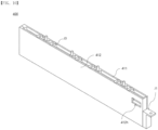
- FIG. 4 is a front perspective view of a supplementary wall 400 included in a battery pack according to a first embodiment
- FIG. 5 is a rear perspective view of the supplementary wall 400 of FIG. 4 .
- the supplementary wall (400) includes a main joint (J1) projecting forwardly at its front end, and is engaged with the main wall (200) in such a way that the main joint (J1) is inserted into the main wall (200).
- the supplementary wall 400 may be secured to the main wall 200 in such a way that the inserted main joints J1 and the main wall 200 are screwed together.
- the supplementary wall (400) includes a main joint (J1) projecting forwardly at its front end, and is engaged with the main wall (200) in such a way that the main joint (J1) is inserted into the main wall (200).
- the supplementary wall 400 may be secured to the main wall 200 by a screwed connection between the inserted main joint J1 and the main wall 200.
- the supplementary wall 400 has a hollow structure on the inside.
- the supplementary wall 400 includes a gas flow path 420 formed to extend along a longitudinal direction to allow gas to flow therein, and an opening 430 formed at a rear end to allow the gas flow path 420 to open to the outside. Furthermore, it also includes a first hole 411h formed at one side to allow the gas flow path 420 to open to the outside.
- the supplementary wall 400 is inserted and joined to the main wall 200 by a front end in which the main joint J1 is formed, and by a rear end inserted and joined to the side wall 300 so that the opening 430 is in communication with the gas venting path 331 of the side wall 300.
- the first hole 411h is in communication with the gas flow path 420 by at least one containing space P formed by the supplementary wall 400.
- the containing space P is in communication with the gas venting path 331 of the side wall 300 via the gas flow path 420.
- a front end of the two ends of the gas flow path 420 is closed by a configuration of the main joint J1 or the like, as shown in FIG. 4 , and a rear end is opened by an opening 430.
- a top joint J2 may be formed that is engageable with an upper cover that is engaged with the pack case 1000 to cover the cell stack contained in the pack case 1000.
- FIG. 6 is an exploded perspective view of the supplementary wall 400 of FIG. 4 .
- the supplementary wall 400 includes a first partition member 411 and a second partition member 412 that engages the first partition member 411, as shown in FIG. 6 .
- the first partition member 411 may include a vertically perforated wall joint J3 for screw connection to an inner surface that is coupled to the second partition member 412, as shown in FIG. 6 . More specifically, the wall joint J3 included in the first partition member 411 is preferably formed on each of the ribs L as shown in FIG. 6 .
- the second partition member 412 may also include a wall joint J3 vertically perforated for screw connection on the inner side where it is coupled with the first partition member 411.
- the wall joint J3 included in the first partition member 411 and the second partition member 412 are preferably formed in positions corresponding to each other up and down. Therefore, when the first partition member 411 and the second partition member 412 are engaged against each other, the wall joint J3 formed on each of the partition members are overlapped in a position corresponding to each other in the vertical direction, and the first partition member 411 and the second partition member 412 are engaged by a bolt or the like penetrating the wall joint J3 formed on each of the partition members.
- a bolt through each of the wall joints J3 may also penetrate the base plate 100 of the pack case 1000 to engage and secure the supplementary wall 400 with the base plate 100.
- the bolts penetrate the ribs L of the first partition member 411 in a vertical direction to engage the supplementary wall 400.
- the first partition member 411 includes a pair of ribs L formed extending along the longitudinal direction of the supplementary wall 400.
- the pair of ribs L is configured to be spaced apart by a predetermined distance up and down, and the first partition member 411 including the ribs L is coupled with the second partition member 412 so that the space between the ribs L forms the gas flow path 420.
- a passage-shaped gas flow path 420 is formed by covering the space between the ribs L by the second partition member 412.
- the supplementary wall 400 of the present invention includes a gas flow path 420 that is closed on its upper and lower sides by the pair of ribs L, and is closed on both sides by the first partition member 411 and the second partition member 412.
- the gas flow path 420 is closed on the upper and lower sides by the pair of ribs L, and closed on both sides by the first partition member 411 and the second partition member 412.
- the first partition member 411 is penetrated at the rear by extending into the space between the pair of ribs L to open in the rearward direction of the first partition member 411, and the second partition member 412 has a structure with an open rear corresponding to the penetrated area of the first partition member 411 to prevent blockage of the penetrated area of the first partition member 411 when combined with the first partition member 411 as shown in FIG. 5 .
- the penetrated area forms an opening 430 of the supplementary wall 400 by engagement of the first partition member 411 and the second partition member 412.
- At least one of the first partition member (411) or the second partition member (412) coupled with the first partition member (411) includes a first hole (411h) that penetrates between the ribs (L) included in the first partition member (411).
- the gas flow path 420 formed by the coupling of the first partition member 411 and the second partition member 412 can be opened to the outside through the opening 430 and the first hole 411h.
- FIG. 7 is a top view of a pack case 1000 of a battery pack according to a first embodiment.
- the gas flow path 420 formed in the supplementary wall 400, and the gas Gp flowing through the gas venting path 331 of the side wall 300 coupled with the supplementary wall 400, that is, the side frame 330, is discharged to the outside through the gas outlet 321 of the rear frame 320 coupled with the side frame 330.
- the battery pack according to the first embodiment of the present invention can be effectively vented to the outside through the supplementary wall 400, even if high temperature gases are generated in any one of the containing spaces P in which the cell stack is contained, as shown in FIG. 7 .
- FIG. 8 illustrates a first partition member 411 of a supplementary wall 400 included in a battery pack according to a second embodiment
- FIG. 9 illustrates a perspective view of a supplementary wall 400 including the first partition member 411 of FIG. 8 .
- the battery pack according to a second embodiment of the present invention is characterized in that a plurality of first holes 411h are formed on one side of the supplementary wall 400.
- the supplementary wall 400 included in the battery pack according to the second embodiment of the present invention includes at least two first holes 411h which is formed to penetrate at least one of the first partition member 411 and the second partition member 412 in order to allow the gas flow path 420 to be in communication with the containing space P.
- the plurality of the first holes 411h are preferably configured adjacent to both ends of the supplementary wall 400, as shown.
- first holes 411h are formed adjacent to each of the two ends of the supplementary wall 400 as described above, gases generated by the cell stack while being blocked by the main wall 200 and the sidewalls 300 can travel along the outer surface of the main wall 200 and the side walls 300 and effectively enter the first holes 411h formed at each end of the supplementary wall 400.
- FIG. 10 is a front perspective view of a supplementary wall 400 included in a battery pack according to a third embodiment
- FIG. 11 is a rear perspective view of a supplementary wall 400 included in a battery pack according to a third embodiment.
- the supplementary wall 400 includes a main joint J1 projecting forwardly therefrom, as shown in FIG. 10 , and is engaged with the main wall 200 in such a way that the main joint J1 is inserted into the main wall 200.
- the supplementary wall 400 may be fixed to the main wall 200 by means of the inserted main joint J1 and the main wall 200 being screwed together.
- a top joint J2 may be formed that is engageable with an upper cover that is engaged with the pack case 1000 to cover the cell stack contained in the pack case 1000.
- the battery pack according to a third embodiment of the present invention is characterized in that both the first partition member 411 and the second partition member 412 have a ribbed (L) configuration.
- a battery pack according to a third embodiment of the present invention includes a supplementary wall (400) including a first partition member (411) including a pair of ribs (L) extending along a longitudinal direction on one side, and a second partition member (412) coupled to the first partition member (411) and including a pair of ribs (L) extending along a longitudinal direction on one side.
- first partition member 411 and the second partition member 412 of the supplementary wall 400 included in the battery pack according to the third embodiment each include a pair of ribs L on opposing inner sides.
- FIG. 12 is an exploded perspective view of a supplementary wall 400 included in a battery pack according to a third embodiment
- FIG. 13 is a side view of a second partition member 412 included in the supplementary wall 400 of FIG. 12
- FIG. 14 is a perspective view of the second partition member 412 of FIG. 13
- FIG. 15 is a side view of a first partition member 411 included in the supplementary wall 400 of FIG. 12
- FIG. 16 is a perspective view of the first partition member 411 of FIG. 15 .
- the first partition member 411 and the second partition member 412 each include a pair of ribs L.
- the ribs L of the second partition member 412 are located at the top in order to not overlap the ribs L of the first partition member 411, and the ribs L of the first partition member 411 are located at the bottom in order to not overlap the ribs L of the second partition member 412.
- the space between the pair of ribs L formed at the top in the second partition member 412 forms the upper gas flow path 421 by the engagement of the first partition member 411 and the second partition member 412. Furthermore, the space between the pair of ribs L formed at the bottom in the first partition member 411 forms a lower gas flow path 422 by the combination of the second partition member 412 and the first partition member 411.
- the upper gas flow path 421 and the lower gas flow path 422 are separated and isolated with each other and are designed to be not in communication with each other. Therefore, the ribs L located below the pair of ribs L formed on the second partition member 412 and the ribs L located above the pair of ribs L formed on the first partition member 411 are preferably spaced apart by a predetermined distance.
- the upper gas flow path 421 of the supplementary wall 400 included in the battery pack according to the above third embodiment is formed by being closed on its upper surface by a pair of ribs L formed in the second partition member 412, and closed on both sides by the first partition member 411 and the second partition member 412.
- the lower gas flow path 422 is formed by being closed on its upper surface by a pair of ribs L formed in the first partition member 411, and closed on both sides by the first partition member 411 and the second partition member 412.
- the first partition member 411 and the second partition member 412 extend into the space between the pair of ribs L and are penetrated rearward, as shown in FIG. 12 , in order that the space between the ribs L is open toward the rear end of each partition member.
- the supplementary wall 400 included in the battery pack according to the third embodiment includes an upper opening 431 located at the top and a lower opening 432 located at the bottom, as shown in FIG. 11 , wherein the first partition member 411 and the second partition member 412 are engaged.
- the upper opening 431 is in communication with the upper gas flow path 421, and the lower opening 432 is in communication with the lower gas flow path 422.
- the supplementary wall 400 included in the battery pack according to a third embodiment of the present invention is inserted at its rear end into the side wall 300 to allow the upper opening 431 and the lower opening 432 to be in communication with the gas venting path 331 of the side wall 300.
- the second partition member 412 may include a wall joint J3 penetrated in a vertically oriented direction for screw connection to an inner surface that engages the first partition member 411, as shown in FIGS. 12 to 14 . More specifically, the wall joint J3 included in the second partition member 412 is formed on each rib L preferably.
- the first partition member 411 may also include a vertically perforated wall joint J3 for screw connection to an inner surface that engages the second partition member 412, as shown in FIGS. 12 , 15, and 16 . More specifically, the wall joint J3 included in the first partition member 411 is preferably formed on each rib L corresponding to the position of the wall joint J3 of the second partition member 412. In other words, the wall joint J3 included in the first partition member 411 and the second partition member 412 are formed in positions corresponding to each other up and down, preferably.
- the wall joint J3 formed on each of the partition members are positioned to be consistent with each other in the vertical direction, and the first partition member 411 and the second partition member 412 are joined by a bolt or the like penetrating the wall joint J3 formed on each of the partition members.
- a bolt penetrating each of the wall joints J3 may also penetrate the base plate 100 of the pack case 1000 to engage and secure the supplementary wall 400 and the base plate 100.
- the bolts penetrate perpendicularly through the ribs L of the first partition member 411 to engage the supplementary wall 400.
- the supplementary wall 400 included in the battery pack according to a third embodiment of the present invention is formed with holes on both sides. Specifically, it includes a first hole 411h penetrated to be in communication with a lower gas flow path 422 on one side and a second hole 412h penetrated to be in communication with an upper gas flow path 421 on the other side.
- the first hole 411h is formed by penetrating a lower portion of the first partition member 411 to be in communication with the lower gas path 422, and the second hole 412h is formed by penetrating a lower portion of the second partition member 412 to be in communication with the upper gas path 421.
- the supplementary wall 400 may also include a plurality of first holes 411h and second holes 412h on each side, as may the supplementary wall 400 included in the battery pack according to the second embodiment above.
- FIG. 17 is a perspective view of a pack case 1000 included in a battery pack according to a third embodiment of the present invention.
- the first hole 411h and the second hole 412h are formed on both sides of the supplementary wall 400 to be in communication with respective containing spaces P. That is, any one containing space P may be formed by the main wall 200, the side wall 300, and the at least one supplementary wall 400.
- the containing space P compartmented by the supplementary wall 400 on both sides may be in communication with both the first hole 411h of one supplementary wall 400 and the second hole 412h of the other supplementary wall 400, and the containing space P compartmented by the sidewall 300 on the other side of the supplementary wall 400 may be in communication with either the first hole 411h or the second hole 412h of the supplementary wall 400.
Landscapes
- Chemical & Material Sciences (AREA)
- Chemical Kinetics & Catalysis (AREA)
- Electrochemistry (AREA)
- General Chemical & Material Sciences (AREA)
- Engineering & Computer Science (AREA)
- Manufacturing & Machinery (AREA)
- Gas Exhaust Devices For Batteries (AREA)
- Battery Mounting, Suspending (AREA)
Abstract
Description
- The present invention relates to a battery pack. More particularly, the battery pack of the present invention is characterized in that it contains a plurality of cell stacks each of which containing one or more battery cells and is capable of releasing high temperature gases generated internally to the exterior by using a supplementary wall that separates each cell stack and includes a gas flow path therein.
- This application claims the benefit of priority to
Korean Patent Application No. 10-2022-0068280, filed on June 3, 2022 - Types of secondary batteries include lithium-ion cells, lithium polymer cells, nickelcadmium cells, nickel-hydrogen cells, nickel-zinc cells, etc. These unit secondary battery cells, i.e. unit battery cells, have an operating voltage of about 2.5 V to 4.2 V. Therefore, if a higher output voltage is required, a plurality of battery cells may be connected in series to form a battery pack. In addition, depending on the charge and discharge capacity required for the battery pack, a plurality of battery cells may be connected in parallel to form a battery pack. Thus, the number of battery cells included in the battery pack may be varied depending on the required output voltage or charge/discharge capacity.
- For example, when forming a battery pack by connecting a plurality of battery cells in series/parallel, it is common to first form a cell stack of the plurality of battery cells, and then add other components to form a battery pack using the cell stack.
- Cell stack refers to a component with a plurality of secondary batteries connected in series or parallel, and battery pack refers to a component with a plurality of cell stacks connected in series or parallel to increase capacity, power output, etc.
-
FIG. 1(a) is an exploded perspective view of a typical cell stack mounted in a battery pack. Referring toFIG. 1(a) , a busbar frame and end plates are coupled to the front and rear of the cell stack, respectively, formed by stacking a plurality of battery cells. The cell stack may also be enclosed and protected by a U-shaped module frame or the like, as shown inFIG. 1(b) . - On the other hand, it is important for the battery pack to release the high temperature gases generated by each cell stack effectively. If the high temperature gases generated during the charging and discharging process are not effectively released, heat accumulation will occur, which will accelerate the degradation of the cell stack, and in some cases, ignition or explosion may occur. In addition, the heat of the gases can be transferred to other normally operating cell stacks, resulting in the degradation or explosion of the entire battery cells contained within the battery pack.
-
Korean Patent Application Publication No. 10-2022-0014027 - The present invention is directed to solving the above mentioned problems, and aims to provide a battery pack capable of rapidly venting high temperature gases to the outside when degradation occurs in a cell stack of any one of the plurality of cell stacks, to prevent the battery pack from igniting or exploding.
- Further, it is an object of the present invention to provide a battery pack capable of preventing the transfer of heat of the high temperature gas to other neighboring cell stacks when degradation occurs in any of the cell stacks of the plurality of cell stacks, to prevent thermal runaway occurs.
- Other objects and advantages of the present invention will be understood from the following description, and will become apparent from the example embodiments of the present invention. Furthermore, it will be readily apparent that the objects and advantages of the present invention may be realized by the methods and combinations thereof disclosed in the claims of the patent.
- According to the present invention, a battery pack containing a cell stack including one or more battery cells, including a pack case having a space in which the cell stack is placed, the pack case including: a base plate supporting a lower portion of the cell stack; a main wall extending across the base plate and coupled to a center portion of the base plate; a side wall having a hollow shape and including a gas venting path therein, and coupled along a periphery of an edge of the base plate; and a plurality of supplementary wall having a front end coupled to the main wall, and a rear end coupled to the side walls, wherein the supplementary wall includes a first partition member including a pair of ribs formed to extend along a longitudinal direction of the supplementary wall, and a second partition member coupled to the first partition member, and wherein at least one of the first partition member and the second partition member includes a first hole between the pair of ribs.
- The supplementary wall may be arranged to be separately spaced along the longitudinal direction of the main wall on both sides of the main wall.
- The pair of ribs may be separately spaced up and down by a predetermined distance.
- The second partition member may be coupled with the first partition member in a direction facing the ribs of the first partition member.
- The supplementary wall may include a plurality of the first holes on one side.
- The first partition member may be penetrated at the rear end to open a space between the pair of ribs in a rearward direction of the first partition member.
- The supplementary wall may be inserted at its rear end into the side wall to allow the opening to be in communicating with the gas venting path.
- The supplementary wall may include a gas flow path closed on its upper and lower surfaces by the pair of ribs, and closed on both sides by the first partition member and the second partition member, the gas flow path being open to the outside through the first hole and the opening, respectively.
- The second partition member may include a pair of ribs formed extending along a longitudinal direction on one side, and the supplementary wall may include a second hole penetrating between the ribs included in the second partition member on the other side opposite to the side in which the first hole is formed.
- The ribs of the second partition member may be formed to not overlapping with the ribs formed on the first partition member.
- The ribs of the second partition member are formed to be located on top of a pair of ribs formed on this first partition member, and the first and second holes may be formed on both sides of the supplementary wall at a lower and upper portion, respectively.
- The first partition member and the second partition member may be penetrated at the rear end to open a space between the pair of ribs in a rearward direction of each partition member.
- The supplementary wall may be inserted at its rear end into the side wall to allow the upper opening and the lower opening to be in communication with the gas venting path.
- The supplementary wall may include a plurality of the first hole and the second hole on each side.
- The supplementary wall, including an upper gas flow path located at the top, closed on its upper and lower sides by a pair of ribs formed in the second partition member, and closed on both sides by the first partition member and the second partition member, and a lower gas flow path located at the bottom, closed on its upper and lower sides by a pair of ribs formed in the first partition member and closed on both sides by the first partition member and the second partition member, and the upper gas flow path and the lower gas flow path may not be in communication with each other within the supplementary wall.
- According to the present invention, it is possible to prevent the battery pack from igniting or exploding even if degradation or high temperature gases are generated in the cell stack contained in the battery pack.
- In addition, according to the present invention, it is possible to prevent thermal runaway caused by transferring high temperature gas generated in a cell stack to a neighboring other cell stack.
- Furthermore, according to the present invention, a plurality of a rib shape can be applied to a wall installed within the battery pack and separating each cell stack to improve rigidity while forming a pathway for gas transfer.
-
-
FIG. 1 is an exploded perspective view of a conventional cell stack. -
FIG. 2 is a perspective view of a pack case of the present invention. -
FIG. 3 illustrates the supplementary wall combined with the base plate. -
FIG. 4 is a front perspective view of a supplementary wall contained in a battery pack according to a first embodiment. -
FIG. 5 is a rear perspective view of the supplementary wall fromFIG. 4 . -
FIG. 6 is an exploded perspective view of the supplementary wall fromFIG. 4 . -
FIG. 7 is a top view of a pack case of a battery pack according to a first embodiment. -
FIG. 8 is a diagram illustrating a first partition member of a supplementary wall included in a battery pack according to a second embodiment. -
FIG. 9 is a perspective view of a supplementary wall including the first partition member ofFIG. 8 . -
FIG. 10 is a front perspective view of a supplementary wall included in a battery pack according to a third embodiment. -
FIG. 11 is a rear perspective view of the supplementary wall fromFIG. 10 . -
FIG. 12 is an exploded perspective view of the supplementary wall ofFIG. 10 . -
FIG. 13 is a side view of a second partition member included in the supplementary wall ofFIG. 12 . -
FIG. 14 is a perspective view of the second partition member ofFIG. 13 . -
FIG. 15 is a side view of a first partition member included in the supplementary wall ofFIG. 12 . -
FIG. 16 is a perspective view of the first partition member ofFIG. 15 . -
FIG. 17 is a perspective view of a pack case included in a battery pack according to a third embodiment. - Hereinafter, the present invention will be described in detail. Prior to this, terms or words used in the present specification and claims should not be restrictively interpreted as ordinary meanings or dictionary-based meanings, but should be interpreted as meanings and concepts consistent with the technical ideas of the present invention on the basis of the principle that an inventor can properly define the concept of a term to describe and explain his or her invention in the best way.
- Therefore, the exemplary embodiments described herein and the configurations illustrated in the drawings in present disclosure are just a preferred embodiments of the invention and are not representative of all of the technical ideas of the invention, so that it is to be understood that there may be various equivalents and modifications that may be substituted for them in the present invention.
- Furthermore, in the description of the invention, detailed descriptions of relevant known configurations or features are ruled out if it is determined that the detailed description would obscure the essence of the invention.
- The embodiments disclosed herein are provided for more perfect explanation of the present disclosure, and thus the shape, size and the like of components may be exaggerated, omitted or simplified in the drawings for better understanding. Thus, the size and ratio of components in the drawings do not wholly reflect the actual size and ratio.
- The present invention relates to a battery pack having a structure capable of separating a space in which a plurality of cell stacks is contained, and at the same time, in the event of high temperature gases being generated in any one of the cell stacks, rapidly releasing the gases to the outside. Here, the cell stack may be in the form of one or more battery cells stacked, as shown in
Figure 1(a) , or in the form of a battery module enclosed by a module frame around its perimeter, as shown inFigure 1(b) . - A battery pack of the present invention includes a pack case (1000) that provides a space in which a cell stack is located.
-
FIG. 2 is a perspective view of thepack case 1000 of the present invention. - The
pack case 1000 includes abase plate 100, amain wall 200,side walls 300, and asupplementary wall 400, as shown in theFIG. 2 . - In addition to the
pack case 1000 above, the battery pack of the present invention may further include a top cover (not shown). The top cover may be combined with thepack case 1000 to form a single housing that contains a plurality of cell stacks. - The
base plate 100 is positioned at a lower portion of the battery pack, in a configuration wherein the cell stack is settled, and supports a lower portion of the cell stack. - The
main wall 200 is formed to extend across thebase plate 100 and is coupled to the center of thebase plate 100. - This
main wall 200 divides the space inside thepack case 1000 into two main sections so that cell stacks on both sides settle on thebase plate 100 symmetrically with respect to each other relative to themain wall 200. In other words, cell stacks located on one side of themain wall 200 and cell stacks located on the other side of themain wall 200 are separated by themain wall 200. - Inside the
main wall 200 may be located wires or busbars or the like that are electrically connected to the cell stacks settling on thebase plate 100. Here, each cell stack is settled on thebase plate 100 with its included end plate facing themain wall 200. - The
side wall 300 is coupled along the periphery of the edge of thebase plate 100 in a hollow form. - The
side wall 300 provides support for the side portions of cell stacks settling on thebase plate 100 and provides protection from the outside. - The
side wall 300 having the hollow structure includes agas venting path 331 inside which gas can flow. - The
side wall 300 includes afront frame 310, arear frame 320, and a pair of side frames 330, as shown inFIG. 2 . - The
front frame 310 andrear frame 320 support one side of the outermost cell stack, and theside frame 330 supports the rear of the settled cell stack. - The
gas venting path 331 is preferably included in theside frame 330. In addition, a gas venting 331 may also be formed in a portion of thefront frame 310 or therear frame 320 to be in communication with thegas venting path 331 of theside frame 330. - The
side wall 300 may further include agas outlet 321 through which agas venting path 331 formed in theside wall 300 is open to the outside. - The
supplementary wall 400 is coupled to thebase plate 100 to repartition the containing space P partitioned by themain wall 200. -
FIG. 3 illustrates asupplementary wall 400 coupled to thebase plate 100. - The
supplementary wall 400 formed by the coupling of thefirst partition member 411 and thesecond partition member 412 is coupled at both ends to themain wall 200 and theside wall 300, respectively, as shown inFIG. 3 . - The
supplementary walls 400 are arranged to be spaced apart at regular intervals along the longitudinal direction of themain wall 200 on both sides of themain wall 200, as shown inFIG. 2 . Here, the cell stack is contained in a containing space P partitioned by themain wall 200, and a pair of neighboringsupplementary walls 400, respectively. - The
supplementary wall 400 of the present invention is characterized in that it has the form of a pair of partition members coupled together, and includes agas flow path 420 formed due to a ribbed structure (L) formed on the coupling surface of the partition members, and a hole penetrated to allow thegas flow path 420 to be in communication with the containing space (P). - The battery pack of the present invention, the
supplementary wall 400 can be categorized into several embodiments based on the rib structure and the hole structure. -
FIG. 4 to FIG. 7 relate to asupplementary wall 400 included in a battery pack according to a first embodiment,FIG. 8 to FIG. 9 relate to asupplementary wall 400 included in a battery pack according to a second embodiment, andFIG. 10 to FIG. 17 relate to asupplementary wall 400 included in a battery pack according to a third embodiment. - Hereinafter, each embodiment will be described with reference to the accompanying drawings.
-
FIG. 4 is a front perspective view of asupplementary wall 400 included in a battery pack according to a first embodiment, andFIG. 5 is a rear perspective view of thesupplementary wall 400 ofFIG. 4 . - The supplementary wall (400) includes a main joint (J1) projecting forwardly at its front end, and is engaged with the main wall (200) in such a way that the main joint (J1) is inserted into the main wall (200). Here, the
supplementary wall 400 may be secured to themain wall 200 in such a way that the inserted main joints J1 and themain wall 200 are screwed together. - The supplementary wall (400) includes a main joint (J1) projecting forwardly at its front end, and is engaged with the main wall (200) in such a way that the main joint (J1) is inserted into the main wall (200). Here, the
supplementary wall 400 may be secured to themain wall 200 by a screwed connection between the inserted main joint J1 and themain wall 200. - The
supplementary wall 400 has a hollow structure on the inside. Specifically, thesupplementary wall 400 includes agas flow path 420 formed to extend along a longitudinal direction to allow gas to flow therein, and anopening 430 formed at a rear end to allow thegas flow path 420 to open to the outside. Furthermore, it also includes afirst hole 411h formed at one side to allow thegas flow path 420 to open to the outside. - The
supplementary wall 400 is inserted and joined to themain wall 200 by a front end in which the main joint J1 is formed, and by a rear end inserted and joined to theside wall 300 so that theopening 430 is in communication with thegas venting path 331 of theside wall 300. In this case, thefirst hole 411h is in communication with thegas flow path 420 by at least one containing space P formed by thesupplementary wall 400. Thus, the containing space P is in communication with thegas venting path 331 of theside wall 300 via thegas flow path 420. - A front end of the two ends of the
gas flow path 420 is closed by a configuration of the main joint J1 or the like, as shown inFIG. 4 , and a rear end is opened by anopening 430. - On an upper side of the
supplementary wall 400, a top joint J2 may be formed that is engageable with an upper cover that is engaged with thepack case 1000 to cover the cell stack contained in thepack case 1000. -
FIG. 6 is an exploded perspective view of thesupplementary wall 400 ofFIG. 4 . - The
supplementary wall 400 includes afirst partition member 411 and asecond partition member 412 that engages thefirst partition member 411, as shown inFIG. 6 . - The
first partition member 411 may include a vertically perforated wall joint J3 for screw connection to an inner surface that is coupled to thesecond partition member 412, as shown inFIG. 6 . More specifically, the wall joint J3 included in thefirst partition member 411 is preferably formed on each of the ribs L as shown inFIG. 6 . - The
second partition member 412 may also include a wall joint J3 vertically perforated for screw connection on the inner side where it is coupled with thefirst partition member 411. Here, the wall joint J3 included in thefirst partition member 411 and thesecond partition member 412 are preferably formed in positions corresponding to each other up and down. Therefore, when thefirst partition member 411 and thesecond partition member 412 are engaged against each other, the wall joint J3 formed on each of the partition members are overlapped in a position corresponding to each other in the vertical direction, and thefirst partition member 411 and thesecond partition member 412 are engaged by a bolt or the like penetrating the wall joint J3 formed on each of the partition members. In this case, a bolt through each of the wall joints J3 may also penetrate thebase plate 100 of thepack case 1000 to engage and secure thesupplementary wall 400 with thebase plate 100. Here, the bolts penetrate the ribs L of thefirst partition member 411 in a vertical direction to engage thesupplementary wall 400. - The
first partition member 411 includes a pair of ribs L formed extending along the longitudinal direction of thesupplementary wall 400. - The pair of ribs L is configured to be spaced apart by a predetermined distance up and down, and the
first partition member 411 including the ribs L is coupled with thesecond partition member 412 so that the space between the ribs L forms thegas flow path 420. In other words, a passage-shapedgas flow path 420 is formed by covering the space between the ribs L by thesecond partition member 412. - In other words, the
supplementary wall 400 of the present invention includes agas flow path 420 that is closed on its upper and lower sides by the pair of ribs L, and is closed on both sides by thefirst partition member 411 and thesecond partition member 412. - The
gas flow path 420 is closed on the upper and lower sides by the pair of ribs L, and closed on both sides by thefirst partition member 411 and thesecond partition member 412. - It is preferable that the
first partition member 411 is penetrated at the rear by extending into the space between the pair of ribs L to open in the rearward direction of thefirst partition member 411, and thesecond partition member 412 has a structure with an open rear corresponding to the penetrated area of thefirst partition member 411 to prevent blockage of the penetrated area of thefirst partition member 411 when combined with thefirst partition member 411 as shown inFIG. 5 . - The penetrated area forms an
opening 430 of thesupplementary wall 400 by engagement of thefirst partition member 411 and thesecond partition member 412. - Further, at least one of the first partition member (411) or the second partition member (412) coupled with the first partition member (411) includes a first hole (411h) that penetrates between the ribs (L) included in the first partition member (411).
- Therefore, the
gas flow path 420 formed by the coupling of thefirst partition member 411 and thesecond partition member 412 can be opened to the outside through theopening 430 and thefirst hole 411h. -
FIG. 7 is a top view of apack case 1000 of a battery pack according to a first embodiment. - Referring to the partially enlarged view of
FIG. 7 and the gas flow path, thegas flow path 420 formed in thesupplementary wall 400, and the gas Gp flowing through thegas venting path 331 of theside wall 300 coupled with thesupplementary wall 400, that is, theside frame 330, is discharged to the outside through thegas outlet 321 of therear frame 320 coupled with theside frame 330. - The battery pack according to the first embodiment of the present invention can be effectively vented to the outside through the
supplementary wall 400, even if high temperature gases are generated in any one of the containing spaces P in which the cell stack is contained, as shown inFIG. 7 . -
FIG. 8 illustrates afirst partition member 411 of asupplementary wall 400 included in a battery pack according to a second embodiment, andFIG. 9 illustrates a perspective view of asupplementary wall 400 including thefirst partition member 411 ofFIG. 8 . - The battery pack according to a second embodiment of the present invention is characterized in that a plurality of
first holes 411h are formed on one side of thesupplementary wall 400. - The
supplementary wall 400 included in the battery pack according to the second embodiment of the present invention, as shown inFigures 8 and9 , includes at least twofirst holes 411h which is formed to penetrate at least one of thefirst partition member 411 and thesecond partition member 412 in order to allow thegas flow path 420 to be in communication with the containing space P. The plurality of thefirst holes 411h are preferably configured adjacent to both ends of thesupplementary wall 400, as shown. - If the
first holes 411h are formed adjacent to each of the two ends of thesupplementary wall 400 as described above, gases generated by the cell stack while being blocked by themain wall 200 and thesidewalls 300 can travel along the outer surface of themain wall 200 and theside walls 300 and effectively enter thefirst holes 411h formed at each end of thesupplementary wall 400. -
FIG. 10 is a front perspective view of asupplementary wall 400 included in a battery pack according to a third embodiment, andFIG. 11 is a rear perspective view of asupplementary wall 400 included in a battery pack according to a third embodiment. - The
supplementary wall 400 includes a main joint J1 projecting forwardly therefrom, as shown inFIG. 10 , and is engaged with themain wall 200 in such a way that the main joint J1 is inserted into themain wall 200. Here, thesupplementary wall 400 may be fixed to themain wall 200 by means of the inserted main joint J1 and themain wall 200 being screwed together. - In addition, on an upper side of the
supplementary wall 400, a top joint J2 may be formed that is engageable with an upper cover that is engaged with thepack case 1000 to cover the cell stack contained in thepack case 1000. - The battery pack according to a third embodiment of the present invention is characterized in that both the
first partition member 411 and thesecond partition member 412 have a ribbed (L) configuration. - More specifically, a battery pack according to a third embodiment of the present invention includes a supplementary wall (400) including a first partition member (411) including a pair of ribs (L) extending along a longitudinal direction on one side, and a second partition member (412) coupled to the first partition member (411) and including a pair of ribs (L) extending along a longitudinal direction on one side.
- In other words, the
first partition member 411 and thesecond partition member 412 of thesupplementary wall 400 included in the battery pack according to the third embodiment each include a pair of ribs L on opposing inner sides. -
FIG. 12 is an exploded perspective view of asupplementary wall 400 included in a battery pack according to a third embodiment,FIG. 13 is a side view of asecond partition member 412 included in thesupplementary wall 400 ofFIG. 12 ,FIG. 14 is a perspective view of thesecond partition member 412 ofFIG. 13 ,FIG. 15 is a side view of afirst partition member 411 included in thesupplementary wall 400 ofFIG. 12 , andFIG. 16 is a perspective view of thefirst partition member 411 ofFIG. 15 . - According to
FIG. 12 above, thefirst partition member 411 and thesecond partition member 412 each include a pair of ribs L. - As shown in
FIG. 12 , the ribs L of thesecond partition member 412 are located at the top in order to not overlap the ribs L of thefirst partition member 411, and the ribs L of thefirst partition member 411 are located at the bottom in order to not overlap the ribs L of thesecond partition member 412. - The space between the pair of ribs L formed at the top in the
second partition member 412 forms the uppergas flow path 421 by the engagement of thefirst partition member 411 and thesecond partition member 412. Furthermore, the space between the pair of ribs L formed at the bottom in thefirst partition member 411 forms a lowergas flow path 422 by the combination of thesecond partition member 412 and thefirst partition member 411. Here, the uppergas flow path 421 and the lowergas flow path 422 are separated and isolated with each other and are designed to be not in communication with each other. Therefore, the ribs L located below the pair of ribs L formed on thesecond partition member 412 and the ribs L located above the pair of ribs L formed on thefirst partition member 411 are preferably spaced apart by a predetermined distance. - Thus, the upper
gas flow path 421 of thesupplementary wall 400 included in the battery pack according to the above third embodiment is formed by being closed on its upper surface by a pair of ribs L formed in thesecond partition member 412, and closed on both sides by thefirst partition member 411 and thesecond partition member 412. Further, the lowergas flow path 422 is formed by being closed on its upper surface by a pair of ribs L formed in thefirst partition member 411, and closed on both sides by thefirst partition member 411 and thesecond partition member 412. - The
first partition member 411 and thesecond partition member 412 extend into the space between the pair of ribs L and are penetrated rearward, as shown inFIG. 12 , in order that the space between the ribs L is open toward the rear end of each partition member. Thus, thesupplementary wall 400 included in the battery pack according to the third embodiment includes anupper opening 431 located at the top and alower opening 432 located at the bottom, as shown inFIG. 11 , wherein thefirst partition member 411 and thesecond partition member 412 are engaged. - The
upper opening 431 is in communication with the uppergas flow path 421, and thelower opening 432 is in communication with the lowergas flow path 422. - The
supplementary wall 400 included in the battery pack according to a third embodiment of the present invention is inserted at its rear end into theside wall 300 to allow theupper opening 431 and thelower opening 432 to be in communication with thegas venting path 331 of theside wall 300. - The
second partition member 412 may include a wall joint J3 penetrated in a vertically oriented direction for screw connection to an inner surface that engages thefirst partition member 411, as shown inFIGS. 12 to 14 . More specifically, the wall joint J3 included in thesecond partition member 412 is formed on each rib L preferably. - The
first partition member 411 may also include a vertically perforated wall joint J3 for screw connection to an inner surface that engages thesecond partition member 412, as shown inFIGS. 12 ,15, and 16 . More specifically, the wall joint J3 included in thefirst partition member 411 is preferably formed on each rib L corresponding to the position of the wall joint J3 of thesecond partition member 412. In other words, the wall joint J3 included in thefirst partition member 411 and thesecond partition member 412 are formed in positions corresponding to each other up and down, preferably. - Therefore, if the
first partition member 411 and thesecond partition member 412 are joined against each other, the wall joint J3 formed on each of the partition members are positioned to be consistent with each other in the vertical direction, and thefirst partition member 411 and thesecond partition member 412 are joined by a bolt or the like penetrating the wall joint J3 formed on each of the partition members. Here, a bolt penetrating each of the wall joints J3 may also penetrate thebase plate 100 of thepack case 1000 to engage and secure thesupplementary wall 400 and thebase plate 100. Here, the bolts penetrate perpendicularly through the ribs L of thefirst partition member 411 to engage thesupplementary wall 400. - The
supplementary wall 400 included in the battery pack according to a third embodiment of the present invention is formed with holes on both sides. Specifically, it includes afirst hole 411h penetrated to be in communication with a lowergas flow path 422 on one side and asecond hole 412h penetrated to be in communication with an uppergas flow path 421 on the other side. - The
first hole 411h is formed by penetrating a lower portion of thefirst partition member 411 to be in communication with thelower gas path 422, and thesecond hole 412h is formed by penetrating a lower portion of thesecond partition member 412 to be in communication with theupper gas path 421. - The
supplementary wall 400 may also include a plurality offirst holes 411h andsecond holes 412h on each side, as may thesupplementary wall 400 included in the battery pack according to the second embodiment above. -
FIG. 17 is a perspective view of apack case 1000 included in a battery pack according to a third embodiment of the present invention. - Referring to
FIG. 17 , thefirst hole 411h and thesecond hole 412h are formed on both sides of thesupplementary wall 400 to be in communication with respective containing spaces P. That is, any one containing space P may be formed by themain wall 200, theside wall 300, and the at least onesupplementary wall 400. - The containing space P compartmented by the
supplementary wall 400 on both sides may be in communication with both thefirst hole 411h of onesupplementary wall 400 and thesecond hole 412h of the othersupplementary wall 400, and the containing space P compartmented by thesidewall 300 on the other side of thesupplementary wall 400 may be in communication with either thefirst hole 411h or thesecond hole 412h of thesupplementary wall 400. - The present invention has been described in more detail above with reference to the drawings and embodiments. However, it is to be understood that the configurations shown in the drawings or embodiments described herein are only one example embodiment of the invention and do not represent all of the technical ideas of the invention, and that there may be various equivalents and modifications that may be substituted for them in the present application.
-
- 10: (Prior art) cell stack
- 1: (Prior art) battery cell
- 2: (Prior art) busbar frame
- 3: (Prior art) end plate
- 4: (Prior art) module frame
- 1000: pack case
- 100: base plate
- 200: main wall
- 300: side wall
- 310: front frame
- 320: rear frame
- 321: gas outlet
- 330: side frame
- 331: gas venting path
- 400: supplementary wall
- 411: first partition member
- 411h: first hole
- 412: second partition member
- 412h: second hole
- 420: gas flow path
- 421: upper gas flow path
- 422: lower gas flow path
- 430: opening
- 431: upper opening
- 432: lower opening
- L: ribs
- P: containing space
- J1: main joint
- J2: upper joint
- J3: wall joint
- Gp: gas
Claims (15)
- A battery pack accommodating a cell stack including one or more battery cells, comprising:a pack case having a space in which the cell stack is placed,wherein the pack case comprising:a base plate supporting a lower portion of the cell stack;a main wall extending across the base plate and coupled to a center portion of the base plate;a side wall having a hollow shape and including a gas venting path therein, and coupled along a periphery of an edge of the base plate; anda plurality of supplementary wall having a front end coupled to the main wall, and a rear end coupled to the side walls,wherein the supplementary wall comprising:a first partition member including a pair of ribs formed to extend along a longitudinal direction of the supplementary wall on one side, and a second partition member coupled to the first partition member, andwherein at least one of the first partition member and the second partition member includes a first hole between the pair of ribs.
- The battery pack of claim 1, wherein the supplementary wall is arranged to be separately spaced along the longitudinal direction of the main wall on both sides of the main wall.
- The battery pack of claim 1, wherein the pair of ribs is separately spaced up and down by a predetermined distance.
- The battery pack of claim 1, wherein the second partition member is coupled with the first partition member in a direction facing the ribs of the first partition member.
- The battery pack of claim 1, wherein the supplementary wall comprises a plurality of the first holes on one side.
- The battery pack of claim 1, wherein the first partition member is penetrated at the rear end to forming an opening in a space between the pair of ribs in a rearward direction of the first partition member.
- The battery pack of claim 6, wherein the supplementary wall is inserted at its rear end into the side wall to allow the opening to be in communication with the gas venting path.
- The battery pack of claim 6, wherein the supplementary wall comprising:a gas flow path closed on its upper and lower surfaces by the pair of ribs, and closed on both sides by the first partition member and the second partition member,the gas flow path being open to the outside through the first hole and the opening, respectively.
- The battery pack of claim 1, wherein the second partition member comprising:a pair of ribs formed extending along a longitudinal direction on one side, andthe supplementary wall comprises a second hole penetrating between the ribs included in the second partition member on the other side opposite to the side in which the first hole is formed.
- The battery pack of claim 9, wherein the ribs of the second partition member is formed to not overlapping with the ribs formed on the first partition member.
- The battery pack of claim 9, wherein the ribs of the second partition member is formed to be located on top of a pair of ribs formed on this first partition member, and
the first and second holes is formed on both sides of the supplementary wall at a lower and upper portion, respectively. - The battery pack of claim 9, wherein the first partition member and the second partition member is penetrated at the rear end to open a space between the pair of ribs in a rearward direction of each of the first partition member and the second partition member.
- The battery pack of claim 12, wherein the supplementary wall is inserted at its rear end into the side wall to allow the upper opening and the lower opening to be in communication with the gas venting path.
- The battery pack of claim 9, wherein the supplementary wall comprises a plurality of the first hole and the second hole on each side.
- The battery pack of claim 9, wherein the supplementary wall comprising:an upper gas flow path located at the top, closed on its upper and lower sides by a pair of ribs formed in the second partition member, and closed on both sides by the first partition member and the second partition member; anda lower gas flow path located at the bottom, closed on its upper and lower sides by a pair of ribs formed in the first partition member and closed on both sides by the first partition member and the second partition member; andthe upper gas flow path and the lower gas flow path is not in communication with each other within the supplementary wall.
Applications Claiming Priority (2)
| Application Number | Priority Date | Filing Date | Title |
|---|---|---|---|
| KR1020220068280A KR20230167969A (en) | 2022-06-03 | 2022-06-03 | Battery pack |
| PCT/KR2023/007552 WO2023234734A1 (en) | 2022-06-03 | 2023-06-01 | Battery pack |
Publications (3)
| Publication Number | Publication Date |
|---|---|
| EP4372889A1 true EP4372889A1 (en) | 2024-05-22 |
| EP4372889A4 EP4372889A4 (en) | 2025-05-07 |
| EP4372889B1 EP4372889B1 (en) | 2026-02-18 |
Family
ID=89025182
Family Applications (1)
| Application Number | Title | Priority Date | Filing Date |
|---|---|---|---|
| EP23816394.3A Active EP4372889B1 (en) | 2022-06-03 | 2023-06-01 | Battery pack |
Country Status (7)
| Country | Link |
|---|---|
| US (1) | US20250141035A1 (en) |
| EP (1) | EP4372889B1 (en) |
| JP (1) | JP7750620B2 (en) |
| KR (1) | KR20230167969A (en) |
| CN (1) | CN117859238A (en) |
| ES (1) | ES3064808T3 (en) |
| WO (1) | WO2023234734A1 (en) |
Families Citing this family (3)
| Publication number | Priority date | Publication date | Assignee | Title |
|---|---|---|---|---|
| KR102754965B1 (en) * | 2023-11-02 | 2025-01-22 | 덕양산업 주식회사 | Battery pack with blocked airtight structure and enhanced rigidity |
| KR20250125663A (en) * | 2024-02-15 | 2025-08-22 | 주식회사 엘지에너지솔루션 | Battery pack |
| CN119764720B (en) * | 2024-12-31 | 2025-09-23 | 蜂巢能源科技股份有限公司 | Floor assembly and battery pack |
Family Cites Families (13)
| Publication number | Priority date | Publication date | Assignee | Title |
|---|---|---|---|---|
| CN110190212B (en) | 2018-12-29 | 2020-02-04 | 比亚迪股份有限公司 | Power battery pack and vehicle |
| CN110190211B (en) | 2018-12-29 | 2020-03-31 | 比亚迪股份有限公司 | Battery tray, power battery package and vehicle |
| US12230820B2 (en) * | 2019-01-09 | 2025-02-18 | Byd Company Limited | Power battery pack and electric vehicle |
| CN111668408B (en) * | 2019-03-08 | 2022-03-15 | 比亚迪股份有限公司 | Battery trays, power battery packs and vehicles |
| CN210454481U (en) * | 2019-08-10 | 2020-05-05 | 茅景海 | Electric automobile disconnect-type battery compartment |
| CN210110904U (en) | 2019-09-19 | 2020-02-21 | 宁德时代新能源科技股份有限公司 | Lower box, battery package and vehicle |
| KR102807685B1 (en) * | 2019-10-15 | 2025-05-13 | 주식회사 엘지에너지솔루션 | Battery Pack |
| KR102802106B1 (en) | 2020-07-28 | 2025-05-02 | 에스케이온 주식회사 | Battery pack |
| WO2022050780A1 (en) * | 2020-09-04 | 2022-03-10 | 주식회사 엘지에너지솔루션 | Battery pack, vehicle, and electronic device comprising same |
| KR102269290B1 (en) * | 2020-11-10 | 2021-06-25 | 주식회사 원진 | Battery cooling apparatus of electric vehicle |
| KR102541278B1 (en) | 2020-11-17 | 2023-06-12 | 주식회사 하나지엔씨 | Modular Sample Collection Booth |
| CN114497854A (en) * | 2021-12-21 | 2022-05-13 | 极氪汽车(宁波杭州湾新区)有限公司 | Battery package box structure |
| KR20230112413A (en) * | 2022-01-20 | 2023-07-27 | 에스케이온 주식회사 | Battery Pack |
-
2022
- 2022-06-03 KR KR1020220068280A patent/KR20230167969A/en active Pending
-
2023
- 2023-06-01 ES ES23816394T patent/ES3064808T3/en active Active
- 2023-06-01 EP EP23816394.3A patent/EP4372889B1/en active Active
- 2023-06-01 WO PCT/KR2023/007552 patent/WO2023234734A1/en not_active Ceased
- 2023-06-01 CN CN202380013276.0A patent/CN117859238A/en active Pending
- 2023-06-01 US US18/683,093 patent/US20250141035A1/en active Pending
- 2023-06-01 JP JP2024510498A patent/JP7750620B2/en active Active
Also Published As
| Publication number | Publication date |
|---|---|
| WO2023234734A1 (en) | 2023-12-07 |
| CN117859238A (en) | 2024-04-09 |
| KR20230167969A (en) | 2023-12-12 |
| JP2024532866A (en) | 2024-09-10 |
| ES3064808T3 (en) | 2026-04-29 |
| US20250141035A1 (en) | 2025-05-01 |
| EP4372889B1 (en) | 2026-02-18 |
| JP7750620B2 (en) | 2025-10-07 |
| EP4372889A4 (en) | 2025-05-07 |
Similar Documents
| Publication | Publication Date | Title |
|---|---|---|
| EP4372889A1 (en) | Battery pack | |
| US12431570B2 (en) | Battery module having partition wall and thermal insulation layer for fire inhibition | |
| EP4020676A1 (en) | Battery pack case, and battery pack including the same | |
| EP3866252A1 (en) | Battery module and battery pack comprising same | |
| EP2064761B1 (en) | Battery module and middle or large-sized battery pack containing the same | |
| EP4471961A1 (en) | Battery and electric apparatus | |
| JP7387904B2 (en) | Battery modules, battery packs containing them, and automobiles | |
| US20230223646A1 (en) | Battery device | |
| KR20230099609A (en) | Battery pack and Vehicle comprising the same | |
| EP4475309A1 (en) | Battery pack | |
| KR102622859B1 (en) | Battery module, battery pack and vehicle including the same | |
| CN118156724A (en) | Battery pack | |
| EP4372890B1 (en) | Battery pack | |
| EP4362197A1 (en) | Battery pack | |
| US20230291059A1 (en) | Battery pack | |
| KR20240012294A (en) | Battery pack and vehicle including the same | |
| EP4489199B1 (en) | Battery pack | |
| US20250316836A1 (en) | Battery pack | |
| EP4668454A1 (en) | Battery pack and vehicle including same | |
| EP4654365A1 (en) | Battery pack and vehicle including same | |
| EP4730510A1 (en) | Battery module, and battery pack and vehicle including same | |
| EP4738569A1 (en) | Battery pack and vehicle including same | |
| EP4475280A1 (en) | Battery pack and vehicle including same | |
| EP4607680A1 (en) | Battery pack | |
| EP4629423A1 (en) | Battery pack |
Legal Events
| Date | Code | Title | Description |
|---|---|---|---|
| STAA | Information on the status of an ep patent application or granted ep patent |
Free format text: STATUS: THE INTERNATIONAL PUBLICATION HAS BEEN MADE |
|
| PUAI | Public reference made under article 153(3) epc to a published international application that has entered the european phase |
Free format text: ORIGINAL CODE: 0009012 |
|
| STAA | Information on the status of an ep patent application or granted ep patent |
Free format text: STATUS: REQUEST FOR EXAMINATION WAS MADE |
|
| 17P | Request for examination filed |
Effective date: 20240216 |
|
| AK | Designated contracting states |
Kind code of ref document: A1 Designated state(s): AL AT BE BG CH CY CZ DE DK EE ES FI FR GB GR HR HU IE IS IT LI LT LU LV MC ME MK MT NL NO PL PT RO RS SE SI SK SM TR |
|
| REG | Reference to a national code |
Ref country code: DE Ref legal event code: R079 Free format text: PREVIOUS MAIN CLASS: H01M0050367000 Ipc: H01M0010613000 Ref country code: DE Ref legal event code: R079 Ref document number: 602023012349 Country of ref document: DE Free format text: PREVIOUS MAIN CLASS: H01M0050367000 Ipc: H01M0010613000 |
|
| A4 | Supplementary search report drawn up and despatched |
Effective date: 20250404 |
|
| RIC1 | Information provided on ipc code assigned before grant |
Ipc: H01M 50/358 20210101ALI20250331BHEP Ipc: H01M 50/367 20210101ALI20250331BHEP Ipc: H01M 50/244 20210101ALI20250331BHEP Ipc: H01M 50/24 20210101ALI20250331BHEP Ipc: H01M 50/289 20210101ALI20250331BHEP Ipc: H01M 50/209 20210101ALI20250331BHEP Ipc: H01M 50/204 20210101ALI20250331BHEP Ipc: H01M 10/625 20140101ALI20250331BHEP Ipc: H01M 10/613 20140101AFI20250331BHEP |
|
| STAA | Information on the status of an ep patent application or granted ep patent |
Free format text: STATUS: EXAMINATION IS IN PROGRESS |
|
| 17Q | First examination report despatched |
Effective date: 20250808 |
|
| DAV | Request for validation of the european patent (deleted) | ||
| DAX | Request for extension of the european patent (deleted) | ||
| GRAP | Despatch of communication of intention to grant a patent |
Free format text: ORIGINAL CODE: EPIDOSNIGR1 |
|
| STAA | Information on the status of an ep patent application or granted ep patent |
Free format text: STATUS: GRANT OF PATENT IS INTENDED |
|
| INTG | Intention to grant announced |
Effective date: 20251106 |
|
| GRAS | Grant fee paid |
Free format text: ORIGINAL CODE: EPIDOSNIGR3 |
|
| P01 | Opt-out of the competence of the unified patent court (upc) registered |
Free format text: CASE NUMBER: UPC_APP_0015379_4372889/2025 Effective date: 20251201 |
|
| GRAA | (expected) grant |
Free format text: ORIGINAL CODE: 0009210 |
|
| STAA | Information on the status of an ep patent application or granted ep patent |
Free format text: STATUS: THE PATENT HAS BEEN GRANTED |
|
| AK | Designated contracting states |
Kind code of ref document: B1 Designated state(s): AL AT BE BG CH CY CZ DE DK EE ES FI FR GB GR HR HU IE IS IT LI LT LU LV MC ME MK MT NL NO PL PT RO RS SE SI SK SM TR |
|
| REG | Reference to a national code |
Ref country code: CH Ref legal event code: F10 Free format text: ST27 STATUS EVENT CODE: U-0-0-F10-F00 (AS PROVIDED BY THE NATIONAL OFFICE) Effective date: 20260218 Ref country code: GB Ref legal event code: FG4D |
|
| REG | Reference to a national code |
Ref country code: IE Ref legal event code: FG4D |
|
| REG | Reference to a national code |
Ref country code: DE Ref legal event code: R096 Ref document number: 602023012349 Country of ref document: DE |
|
| REG | Reference to a national code |
Ref country code: ES Ref legal event code: FG2A Ref document number: 3064808 Country of ref document: ES Kind code of ref document: T3 Effective date: 20260429 |