EP4372875A1 - Cover assembly, battery and electronic device - Google Patents
Cover assembly, battery and electronic device Download PDFInfo
- Publication number
- EP4372875A1 EP4372875A1 EP23208130.7A EP23208130A EP4372875A1 EP 4372875 A1 EP4372875 A1 EP 4372875A1 EP 23208130 A EP23208130 A EP 23208130A EP 4372875 A1 EP4372875 A1 EP 4372875A1
- Authority
- EP
- European Patent Office
- Prior art keywords
- pressure relief
- relief hole
- heat
- resistant sheet
- boss
- Prior art date
- Legal status (The legal status is an assumption and is not a legal conclusion. Google has not performed a legal analysis and makes no representation as to the accuracy of the status listed.)
- Pending
Links
Images




Classifications
-
- H—ELECTRICITY
- H01—ELECTRIC ELEMENTS
- H01M—PROCESSES OR MEANS, e.g. BATTERIES, FOR THE DIRECT CONVERSION OF CHEMICAL ENERGY INTO ELECTRICAL ENERGY
- H01M50/00—Constructional details or processes of manufacture of the non-active parts of electrochemical cells other than fuel cells, e.g. hybrid cells
- H01M50/30—Arrangements for facilitating escape of gases
- H01M50/394—Gas-pervious parts or elements
-
- H—ELECTRICITY
- H01—ELECTRIC ELEMENTS
- H01M—PROCESSES OR MEANS, e.g. BATTERIES, FOR THE DIRECT CONVERSION OF CHEMICAL ENERGY INTO ELECTRICAL ENERGY
- H01M50/00—Constructional details or processes of manufacture of the non-active parts of electrochemical cells other than fuel cells, e.g. hybrid cells
- H01M50/10—Primary casings; Jackets or wrappings
- H01M50/147—Lids or covers
-
- H—ELECTRICITY
- H01—ELECTRIC ELEMENTS
- H01M—PROCESSES OR MEANS, e.g. BATTERIES, FOR THE DIRECT CONVERSION OF CHEMICAL ENERGY INTO ELECTRICAL ENERGY
- H01M50/00—Constructional details or processes of manufacture of the non-active parts of electrochemical cells other than fuel cells, e.g. hybrid cells
- H01M50/10—Primary casings; Jackets or wrappings
- H01M50/116—Primary casings; Jackets or wrappings characterised by the material
- H01M50/117—Inorganic material
-
- H—ELECTRICITY
- H01—ELECTRIC ELEMENTS
- H01M—PROCESSES OR MEANS, e.g. BATTERIES, FOR THE DIRECT CONVERSION OF CHEMICAL ENERGY INTO ELECTRICAL ENERGY
- H01M50/00—Constructional details or processes of manufacture of the non-active parts of electrochemical cells other than fuel cells, e.g. hybrid cells
- H01M50/10—Primary casings; Jackets or wrappings
- H01M50/14—Primary casings; Jackets or wrappings for protecting against damage caused by external factors
- H01M50/143—Fireproof; Explosion-proof
-
- H—ELECTRICITY
- H01—ELECTRIC ELEMENTS
- H01M—PROCESSES OR MEANS, e.g. BATTERIES, FOR THE DIRECT CONVERSION OF CHEMICAL ENERGY INTO ELECTRICAL ENERGY
- H01M50/00—Constructional details or processes of manufacture of the non-active parts of electrochemical cells other than fuel cells, e.g. hybrid cells
- H01M50/30—Arrangements for facilitating escape of gases
-
- H—ELECTRICITY
- H01—ELECTRIC ELEMENTS
- H01M—PROCESSES OR MEANS, e.g. BATTERIES, FOR THE DIRECT CONVERSION OF CHEMICAL ENERGY INTO ELECTRICAL ENERGY
- H01M50/00—Constructional details or processes of manufacture of the non-active parts of electrochemical cells other than fuel cells, e.g. hybrid cells
- H01M50/30—Arrangements for facilitating escape of gases
- H01M50/342—Non-re-sealable arrangements
- H01M50/3425—Non-re-sealable arrangements in the form of rupturable membranes or weakened parts, e.g. pierced with the aid of a sharp member
-
- H—ELECTRICITY
- H01—ELECTRIC ELEMENTS
- H01M—PROCESSES OR MEANS, e.g. BATTERIES, FOR THE DIRECT CONVERSION OF CHEMICAL ENERGY INTO ELECTRICAL ENERGY
- H01M2220/00—Batteries for particular applications
- H01M2220/20—Batteries in motive systems, e.g. vehicle, ship, plane
-
- H—ELECTRICITY
- H01—ELECTRIC ELEMENTS
- H01M—PROCESSES OR MEANS, e.g. BATTERIES, FOR THE DIRECT CONVERSION OF CHEMICAL ENERGY INTO ELECTRICAL ENERGY
- H01M50/00—Constructional details or processes of manufacture of the non-active parts of electrochemical cells other than fuel cells, e.g. hybrid cells
- H01M50/10—Primary casings; Jackets or wrappings
- H01M50/147—Lids or covers
- H01M50/148—Lids or covers characterised by their shape
- H01M50/15—Lids or covers characterised by their shape for prismatic or rectangular cells
-
- Y—GENERAL TAGGING OF NEW TECHNOLOGICAL DEVELOPMENTS; GENERAL TAGGING OF CROSS-SECTIONAL TECHNOLOGIES SPANNING OVER SEVERAL SECTIONS OF THE IPC; TECHNICAL SUBJECTS COVERED BY FORMER USPC CROSS-REFERENCE ART COLLECTIONS [XRACs] AND DIGESTS
- Y02—TECHNOLOGIES OR APPLICATIONS FOR MITIGATION OR ADAPTATION AGAINST CLIMATE CHANGE
- Y02E—REDUCTION OF GREENHOUSE GAS [GHG] EMISSIONS, RELATED TO ENERGY GENERATION, TRANSMISSION OR DISTRIBUTION
- Y02E60/00—Enabling technologies; Technologies with a potential or indirect contribution to GHG emissions mitigation
- Y02E60/10—Energy storage using batteries
Definitions
- the disclosure relates to the technical field of batteries, in particular to a cover assembly, a battery and an electronic device.
- a plurality of batteries When in use, a plurality of batteries are connected in series or in parallel to form a part of a battery pack.
- a pressure relief hole is provided on the cover assembly of each battery, and a boss is provided on the outer circumference of the pressure relief hole.
- the battery When the battery undergoes thermal runaway, the battery will emit high-temperature gas and high-temperature substances, and the high-temperature gas and high-temperature substances will return into the pressure relief hole of the adjacent battery.
- a heat-resistant sheet is now configured to cover the pressure relief hole of the cover assembly of the battery and is connected to the top portion of the boss. Due to the small area of the top portion of the boss, the contact area between the heat-resistant sheet and the boss is small, and the connection is unstable. If there is a high-pressure airflow blowing through the side surface, the heat-resistant sheet is likely to fall, which will affect the safety performance of the battery.
- the purpose of the disclosure is to provide a cover assembly, a battery and an electronic device, so that the heat-resistant sheet is not easily to fall off, while the safety of the battery is ensured.
- a cover assembly includes a cover body, a boss and a heat-resistant sheet.
- a pressure relief hole is provided on the cover body.
- the boss is disposed on the top surface of the cover body, and surrounds the outer periphery of the pressure relief hole.
- the boss encloses a first region, wherein the first region communicates with the pressure relief hole, and together with the pressure relief hole constitute an accommodation space.
- the heat-resistant sheet is disposed in the accommodation space and at least partially covers the pressure relief hole.
- the embodiments of the disclosure provide the heat-resistant sheet in the accommodation space and covers the pressure relief hole.
- the heat-resistant sheet covers an appropriate area and does not have too much connection area with the cover body, so that the battery is able to release pressure smoothly, that is, meeting the requirements of opening the valve smoothly for battery which undergoes thermal runaway, while it is possible to block the high-temperature gas and high-temperature substances falling from other batteries.
- the heat-resistant sheet is placed in the accommodation space and will not fall due to the airflow coming from the side surface. In this way, the heat-resistant sheet has been covering the pressure relief hole to ensure the safety performance of the battery.
- the heat-resistant sheet is disposed in the first region.
- the bottom edge of the inner side wall of the boss is flush with the top edge of the inner side wall of the pressure relief hole.
- the boss is spaced apart from the edge of the pressure relief hole, and the heat-resistant sheet is fixed to a part of the cover body surrounded by the boss.
- the distance between the edge of the pressure relief hole and the boss is 1 mm to 5 mm.
- the boss has an inner side wall surrounding the outer periphery of the pressure relief hole, and the heat-resistant sheet is spaced apart from the inner side wall of the boss.
- the heat-resistant sheet is fixed to the inner side wall of the boss.
- the inner side wall of the boss further has a position-limiting portion extending toward the first region; and an area of an orthographic projection of the position-limiting portion along the thickness direction of the cover body in the pressure relief hole is smaller than the area of the pressure relief hole, and the heat-resistant sheet is located below the position-limiting portion.
- At least a part of the heat-resistant sheet is located in the pressure relief hole.
- the cover assembly further includes: an explosion-proof sheet disposed on the cover body, and the explosion-proof sheet covers the pressure relief hole, and the heat-resistant sheet is connected with the top surface of the explosion-proof sheet.
- the explosion-proof sheet is disposed on the bottom surface of the cover body, and the heat-resistant sheet is disposed in the pressure relief hole.
- the inner side wall of the boss further has a position-limiting portion extending toward the first region; and an area of an orthographic projection of the position-limiting portion along the thickness direction of the cover body in the pressure relief hole is smaller than an area of the pressure relief hole, the heat-resistant sheet is clamped between the position-limiting portion and the explosion-proof sheet.
- the cover assembly further includes: a protection film, the protection film is disposed above the heat-resistant sheet, and the protection film covers the region surrounded by the boss.
- the protection film is fixed to the top surface of the boss.
- the region where the heat-resistant sheet covers the pressure relief hole is further provided with a ventilating portion.
- the heat-resistant sheet is one of glass fiber, mica, ceramic and ceramic rubber.
- An embodiment of the present disclosure further provides a battery including a cover assembly as described in any one of the above embodiments; a housing having an opening closed by the cover assembly; and a battery cell which is disposed in the housing.
- An embodiment of the present disclosure also provides an electronic device including the above-mentioned battery.
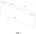
- An embodiment of the present disclosure provides an electronic device including a battery 1 as shown in FIG. 1 .
- the battery 1 includes a cover assembly 10, a housing 20 and a battery cell.
- the housing 20 has an opening 21, and the opening 21 is closed by the cover assembly 10.
- the battery cell is disposed in the housing 20.
- the housing 20 is in the shape of a rectangular box, and the cover assembly 10 is adaptively set in a strip shape.
- the cover assembly 10 may also have other shapes accordingly, as long as the cover assembly 10 is able to seal the opening 21 of the housing 20.
- openings 21 may also be provided at both ends in the length direction, and the cover assembly 10 may cover the openings 21 at both ends.
- the electronic device may be an electric car or an electric motorcycle or the like.
- the cover assembly 10 includes a cover body 11, a boss 12 and a heat-resistant sheet 13.
- a pressure relief hole 111 is provided on the cover body 11, and the battery further includes an explosion-proof sheet 14 disposed at the pressure relief hole 111.
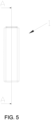
- FIG. 6 is a sectional view of the battery 1 shown in FIG. 5 along the section line "A-A”
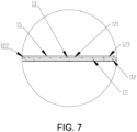
- FIG. 7 shows a partially enlarged view of the pressure relief hole 111 in FIG. 6 .
- the boss 12 is disposed on the top surface of the cover body 11 and surrounds the outer periphery of the pressure relief hole 111.
- the boss 12 encloses a first region 121, that is, the first region 121 is a space enclosed by the boss 12 between the top surface of the cover body 11 and the top surface of the boss 12.
- the first region 121 communicates with the pressure relief hole 111, and together with the pressure relief hole 111 constitute an accommodation space.
- the heat-resistant sheet 13 is disposed in the accommodation space and partially covers the pressure relief hole 111.
- the heat-resistant sheet is placed in the accommodation space and covers the pressure relief hole.
- the heat-resistant sheet covers an appropriate area and does not have too much connection area with the cover body, so that the battery is able to release the pressure smoothly when releasing the pressure, that is, meeting the requirements of opening the valve smoothly for battery which undergoes thermal runaway, while it is possible to block the high-temperature gas and high-temperature substances falling from other batteries.
- the heat-resistant sheet is placed in the accommodation space and will not fall due to the airflow coming from the side surface. In this way, the heat-resistant sheet has been covering the pressure relief hole to ensure the safety performance of the battery.
- the battery 1 in an embodiment of the present disclosure includes a cover assembly 10, a housing 20 and a battery cell.
- the housing 20 has an opening 21, and the opening 21 is closed by the cover assembly 10.
- the battery cell is disposed in the housing 20.
- the housing 20 is in the shape of a rectangular box, and the cover assembly 10 is adaptively set in a strip shape.
- the cover assembly 10 may also have other shapes accordingly, as long as the cover assembly 10 is able to seal the opening 21 of the housing 20.
- openings 21 may also be provided at both ends in the length direction, and the cover assembly 10 may cover the openings 21 at both ends.
- the cover assembly 10 includes a cover body 11, a boss 12 and a heat-resistant sheet 13.
- a pressure relief hole 111 is provided on the cover body 11.
- FIG. 6 is a sectional view of the battery 1 shown in FIG. 5 along the section line "A-A”
- FIG. 7 shows a partially enlarged view of the pressure relief hole 111 in FIG. 6 .
- the boss 12 is disposed on the top surface of the cover body 11 and surrounds the outer periphery of the pressure relief hole 111.
- the boss 12 encloses a first region 121, that is, the first region 121 is a space enclosed by the boss 12 between the top surface of the cover body 11 and the top surface of the boss 12.
- the height of the boss 12 is equal to the height of the first region 121.
- the first region 121 communicates with the pressure relief hole 111, and together with the pressure relief hole 111 constitute an accommodation space.
- the heat-resistant sheet 13 is disposed in the accommodation space and partially covers the pressure relief hole 111.
- the heat-resistant sheet 13 is disposed in the first region 121.
- the boss 12 is spaced apart from the edge of the pressure relief hole 111, and the heat-resistant sheet 13 is fixed to a part of the cover body 1 surrounded by the boss 12, that is, the inner diameter of the pressure relief hole 111 is smaller than the inner diameter of the boss 12, and the cover body 11 protrudes toward the inner side wall 122 and a portion thereof beyond the inner side wall 122 forms an inner edge 112, while the heat-resistant sheet 13 is disposed on the inner edge 112, that is, the heat-resistant sheet 13 is disposed above the cover body 11 and on the inner side of the boss 12.
- the heat-resistant sheet 13 is pasted and fixed on the cover body 11.
- the distance a between an edge of the pressure relief hole 111 and the boss 12 is in the range of 1 mm to 5 mm.
- the distance a between the edge of the pressure relief hole 111 and the boss 12 may be set to 1 mm, 2 mm, 2.5 mm, 3 mm, 4 mm or 5 mm.
- the distance a between the edge of the pressure relief hole 111 and the boss 12 is not overly large to cause the aperture of the pressure relief hole 111 to be too small, otherwise it will hinder the eruption of high-temperature gas, nor is the distance a overly small to cause the heat-resistant sheet 13 to be inconveniently disposed in the first region 121.
- the heat-resistant sheet 13 is set to have a sufficient contact area with the cover body 11 to better position the heat-resistant sheet 13.
- the boss 12 has an inner side wall 122 surrounding the outer periphery of the pressure relief hole 111, and the heat-resistant sheet 13 is spaced apart from the inner side wall 122 of the boss 12.
- the heat-resistant sheet 13 may also be fixed to the inner side wall 122 of the boss 12 without departing from the scope of the present disclosure.
- the inner side wall 122 of the boss 12 further has a position-limiting portion 123 extending toward the first region 121, and an area of the orthographic projection of the position-limiting portion 123 along the thickness direction of the cover body 11 is smaller than the area of the pressure relief hole 111, and the heat-resistant sheet 13 is located below the position-limiting portion 123.
- the heat-resistant sheet 13 set in this way may be stably fixed in the accommodation space and is not easily to fall, thus preventing the heat-resistant sheet 13 from rushing out of the boss 12, and the position-limiting portion 123 may press and hold the heat-resistant sheet 13, which may be set by those skilled in the art according to actual needs.
- the position-limiting portion 123 there may be a gap between the position-limiting portion 123 and the heat-resistant sheet 13, or multiple position-limiting portions 123 may be provided at intervals to press and hold the heat-resistant sheet 13 without departing from the scope of the present disclosure.
- the heat-resistant sheet 13 is placed in the first region 121 first. After the heat-resistant sheet 13 is pasted, the top portion of the boss 12 may be punched to form a position-limiting portion 123. Understandably, there may not be provided with a position-limiting portion.
- the cover assembly 10 further includes a protection film 15 disposed above the heat-resistant sheet 13, and the protection film 15 covers the region surrounded by the boss 12.
- the protection film 15 may be pasted on the top portion of the boss 12, or the protection film 15 may be set in the first region surrounded by the boss 12, and those skilled in the art may make the arrangement according to actual needs.
- the protection film 15 is fixed to the top surface of the boss 12.
- the cover assembly 10 may further include an explosion-proof sheet 14 disposed on the cover body 11, and the explosion-proof sheet 14 covers the pressure relief hole 111.
- the explosion-proof plate 14 is able to ensure the electrical safety of the battery 1, and those skilled in the art may set the arrangement according to actual needs. It should be understood that the explosion-proof plate 14 may not be set.
- a ventilating portion 131 is provided on the region where the heat-resistant sheet 13 covers the pressure relief hole 111.
- the ventilating portion 131 may be set as a hole or a split, and may be in the shape of a cross, a circle, or a square as shown in the figure, and the ventilating portion 131 only needs to realize air ventilation without departing from the scope of the present disclosure.
- the heat-resistant sheet 13 may be set as one of glass fiber, mica, ceramic, and ceramic rubber. Those skilled in the art may make configuration according to actual needs.
- the heat-resistant sheet 13 may have a thickness of 0.2 mm to 1 mm, and may withstand a temperature of up to 1000 degrees Celsius.
- FIG. 8 shows a schematic structural view of the cover assembly 10 in another embodiment of the present disclosure
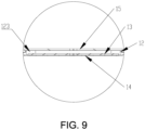
- FIG. 9 shows a partially enlarged view of the pressure relief hole 111 in FIG. 8
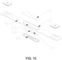
- FIG. 10 is an exploded view of the cover assembly 10 in another embodiment of the present disclosure.
- the bottom edge of the inner side wall 122 of the boss 12 is flush with the top edge of the inner side wall 122 of the pressure relief hole 111. That is to say, the cover body 11 penetrates through from top to bottom, and the first region surrounded by the boss 12 and the pressure relief hole 111 penetrate each other.
- the first region and the pressure relief hole 111 are connected as a whole, and the apertures of the first region and the pressure relief hole 111 are the same.
- the heat-resistant sheet 13 is disposed in the pressure relief hole 111 of the accommodation space and covers the pressure relief hole 111.
- the cover assembly 10 may further include an explosion-proof sheet 14 disposed on the cover body 11, the explosion-proof sheet 14 covers the pressure relief hole 111, and the heat-resistant sheet 13 is connected to the top surface of the explosion-proof sheet 14. That is, the heat-resistant sheet 13 is fixed to the explosion-proof sheet 14, so as to be pasted on the explosion-proof sheet, and the explosion-proof sheet 14 is fixed to the cover body 11, so the heat-resistant sheet 13 is disposed in the accommodation space. In this arrangement, the heat-resistant sheet 13 only needs to cover the region where the explosion-proof sheet 14 is located, thus reducing the use area of the heat-resistant sheet and saves cost. In this embodiment, the heat-resistant sheet 13 is only located in the pressure relief hole 111.
- the heat-resistant sheet 13 may also be configured with a thicker thickness. Under the circumstances, the heat-resistant sheet 13 is disposed in the pressure relief hole 111 set in the accommodation space and the first region 121. The heat-resistant sheet 13 may be spaced apart from the inner side wall 122 of the pressure relief hole 111, or may be connected with the inner side wall 122 of the pressure relief hole 111 without departing from the scope of the present disclosure.
- the cover assembly 10 may not include the explosion-proof sheet 14.
- the heat-resistant sheet 13 is disposed in the pressure relief hole 111, and the heat-resistant sheet 13 may be connected with the hole wall of the pressure relief hole 111, or partially in the first region 121 and connected with the inner side wall of the boss 12.
- the explosion-proof sheet 14 is disposed on the bottom surface of the cover body 11, and the heat-resistant sheet 13 is disposed in the pressure relief hole 111.
- the explosion-proof sheet 14 may also be disposed in the pressure relief hole 111 without departing from the scope of the present disclosure.
- the inner side wall 122 of the boss 12 further has a position-limiting portion 123 extending toward the first region 121, and an area of the orthographic projection of the position-limiting portion 123 along the thickness direction of the cover body 11 is smaller than an area of the pressure relief hole 111, and the heat-resistant sheet 13 is clamped between the position-limiting portion 123 and the explosion-proof sheet 14.
- the heat-resistant sheet 13 set in this way may be stably fixed in the accommodation space and is not easily to fall off, and those skilled in the art may make the arrangement according to actual needs.
- the heat-resistant sheet 13 may be placed in the pressure relief hole 111 first. After the heat-resistant sheet 13 is pasted, the top portion of the boss 12 may be punched to form a position-limiting portion 123. It is understandable that there may be no position-limiting portion 123.
- the cover assembly 10 further includes a protection film 15 disposed above the heat-resistant sheet 13, and the protection film 15 covers the region surrounded by the boss 12.
- the protection film 15 may be pasted on the top portion of the boss 12, or the protection film 15 may be placed in the inner hole of the boss 12, and those skilled in the art may make the arrangement according to actual needs.
- a ventilating portion 131 is provided on the region where the heat-resistant sheet 13 covers the pressure relief hole 111.
- the ventilating portion 131 may be set as a hole or a split, and may be in the shape of a cross, a circle, or a square as shown in the figure, and the ventilating portion 131 only needs to realize air ventilation without departing from the scope of the present disclosure.
Landscapes
- Chemical & Material Sciences (AREA)
- Chemical Kinetics & Catalysis (AREA)
- Electrochemistry (AREA)
- General Chemical & Material Sciences (AREA)
- Inorganic Chemistry (AREA)
- Gas Exhaust Devices For Batteries (AREA)
- Sealing Battery Cases Or Jackets (AREA)
- Battery Mounting, Suspending (AREA)
Abstract
A cover assembly (10), a battery (1) and an electronic device are provided. The cover assembly (10) includes a cover body (11), a boss (12), and a heat-resistant sheet (13). A pressure relief hole (111) is provided on the cover body (11). The boss (12) is disposed on the top surface of the cover body (11), and surrounds the outer periphery of the pressure relief hole (111). The boss (12) encloses a first region (121) communicated with the pressure relief hole (111), and together with the pressure relief hole (111) constitute an accommodation space. The heat-resistant sheet (13) is disposed in the accommodation space and at least partially covers the pressure relief hole (111).
Description
- The disclosure relates to the technical field of batteries, in particular to a cover assembly, a battery and an electronic device.
- In recent years, the rapid rise of new energy vehicles has significantly facilitated sustainable development of society and the harmonious coexistence of human beings and the environment. Among various conceptual new energy vehicles, it is already achievable to put electric vehicles into mass production technically, and electric vehicles have received more and more attention and become favorable with the support of the government. As a solution to energy and environmental issues, the key technology of electric vehicles is the rechargeable battery assembly that replaces gasoline fuel engines as the power source.
- When in use, a plurality of batteries are connected in series or in parallel to form a part of a battery pack. A pressure relief hole is provided on the cover assembly of each battery, and a boss is provided on the outer circumference of the pressure relief hole. When the battery undergoes thermal runaway, the battery will emit high-temperature gas and high-temperature substances, and the high-temperature gas and high-temperature substances will return into the pressure relief hole of the adjacent battery. In order to prevent such accidents, a heat-resistant sheet is now configured to cover the pressure relief hole of the cover assembly of the battery and is connected to the top portion of the boss. Due to the small area of the top portion of the boss, the contact area between the heat-resistant sheet and the boss is small, and the connection is unstable. If there is a high-pressure airflow blowing through the side surface, the heat-resistant sheet is likely to fall, which will affect the safety performance of the battery.
- The purpose of the disclosure is to provide a cover assembly, a battery and an electronic device, so that the heat-resistant sheet is not easily to fall off, while the safety of the battery is ensured.
- In order to solve the above technical problems, the embodiment of the disclosure provides a cover assembly includes a cover body, a boss and a heat-resistant sheet. A pressure relief hole is provided on the cover body. The boss is disposed on the top surface of the cover body, and surrounds the outer periphery of the pressure relief hole. The boss encloses a first region, wherein the first region communicates with the pressure relief hole, and together with the pressure relief hole constitute an accommodation space. The heat-resistant sheet is disposed in the accommodation space and at least partially covers the pressure relief hole.
- Compared with the related art, the embodiments of the disclosure provide the heat-resistant sheet in the accommodation space and covers the pressure relief hole. The heat-resistant sheet covers an appropriate area and does not have too much connection area with the cover body, so that the battery is able to release pressure smoothly, that is, meeting the requirements of opening the valve smoothly for battery which undergoes thermal runaway, while it is possible to block the high-temperature gas and high-temperature substances falling from other batteries. In addition, the heat-resistant sheet is placed in the accommodation space and will not fall due to the airflow coming from the side surface. In this way, the heat-resistant sheet has been covering the pressure relief hole to ensure the safety performance of the battery.
- In an embodiment, the heat-resistant sheet is disposed in the first region.
- In an embodiment, the bottom edge of the inner side wall of the boss is flush with the top edge of the inner side wall of the pressure relief hole.
- In an embodiment, the boss is spaced apart from the edge of the pressure relief hole, and the heat-resistant sheet is fixed to a part of the cover body surrounded by the boss.
- In an embodiment, the distance between the edge of the pressure relief hole and the boss is 1 mm to 5 mm.
- In an embodiment, the boss has an inner side wall surrounding the outer periphery of the pressure relief hole, and the heat-resistant sheet is spaced apart from the inner side wall of the boss.
- In an embodiment, the heat-resistant sheet is fixed to the inner side wall of the boss.
- In an embodiment, the inner side wall of the boss further has a position-limiting portion extending toward the first region; and an area of an orthographic projection of the position-limiting portion along the thickness direction of the cover body in the pressure relief hole is smaller than the area of the pressure relief hole, and the heat-resistant sheet is located below the position-limiting portion.
- In an embodiment, at least a part of the heat-resistant sheet is located in the pressure relief hole.
- In an embodiment, the cover assembly further includes: an explosion-proof sheet disposed on the cover body, and the explosion-proof sheet covers the pressure relief hole, and the heat-resistant sheet is connected with the top surface of the explosion-proof sheet.
- In an embodiment, the explosion-proof sheet is disposed on the bottom surface of the cover body, and the heat-resistant sheet is disposed in the pressure relief hole.
- In an embodiment, the inner side wall of the boss further has a position-limiting portion extending toward the first region; and an area of an orthographic projection of the position-limiting portion along the thickness direction of the cover body in the pressure relief hole is smaller than an area of the pressure relief hole, the heat-resistant sheet is clamped between the position-limiting portion and the explosion-proof sheet.
- In an embodiment, the cover assembly further includes: a protection film, the protection film is disposed above the heat-resistant sheet, and the protection film covers the region surrounded by the boss.
- In an embodiment, the protection film is fixed to the top surface of the boss.
- In an embodiment, the region where the heat-resistant sheet covers the pressure relief hole is further provided with a ventilating portion.
- In an embodiment, the heat-resistant sheet is one of glass fiber, mica, ceramic and ceramic rubber.
- An embodiment of the present disclosure further provides a battery including a cover assembly as described in any one of the above embodiments; a housing having an opening closed by the cover assembly; and a battery cell which is disposed in the housing.
- An embodiment of the present disclosure also provides an electronic device including the above-mentioned battery.
-
-
FIG. 1 is a schematic structural view of a battery in an embodiment of the disclosure. -
FIG. 2 is a schematic structural view of a housing in an embodiment of the present disclosure. -
FIG. 3 is an exploded view of a cover assembly in an embodiment of the present disclosure. -
FIG. 4 is a schematic structural view of a cover body in an embodiment of the present disclosure. -
FIG. 5 is a schematic structural view of a battery in an embodiment of the present disclosure. -
FIG. 6 is a sectional view along the section line "A-A" inFIG. 5 . -
FIG. 7 is a partially enlarged view of A inFIG. 6 . -
FIG. 8 is a cross-sectional view of a battery in another embodiment of the present disclosure. -
FIG. 9 is a partially enlarged view of B inFIG. 8 . -
FIG. 10 is an exploded view of a cover assembly in another embodiment of the present disclosure. - In order to make the purpose, technical solutions and advantages of the present disclosure clearer, various implementation modes of the present disclosure will be described in detail below in conjunction with the accompanying drawings. However, those of ordinary skill in the art can understand that in each implementation manner of the present disclosure, many technical details are proposed in order to enable readers to better understand the present application. However, even without these technical details and various changes and modifications based on the following embodiments, the technical solution claimed in each claim of the present application may be realized.
- Unless the context requires otherwise, throughout the specification and claims, the word "comprise" and variations thereof, such as "comprising" and "having" are to be read in an open, inclusive sense, i.e., "including, but not limited to".
- Various embodiments of the disclosure will be described in detail below in conjunction with the accompanying drawings, so as to better understand the purpose, features and advantages of the disclosure. It should be understood that the embodiments shown in the accompanying drawings are not intended to limit the scope of the disclosure, but only to illustrate the spirit of the technical solution of the disclosure.
- Reference throughout this specification to "one embodiment" or "an embodiment" means that a particular feature, structure, or characteristic described in connection with the embodiments is included in at least one embodiment. Thus, recitation of "in one embodiment" or "in an embodiment" in various places throughout the specification are not necessarily all referring to the same embodiment. In addition, particular features, structures or characteristics may be combined in any manner in one or more embodiments.
- As used in this specification and the appended claims, the singular forms "a" and "the" include plural referents unless the context clearly dictates otherwise. It should be noted that the term "or" is generally employed in its sense including "and/or" unless the context clearly dictates otherwise.
- In the following description, in order to clearly demonstrate the structure and operation method of the disclosure, many directional words will be used for description. However, terms such as "front", "rear", "left", "right", "outer", "inner", "outward", "inward", "upper", "lower" should be understood for the convenience of description, and should not be construed as a limiting term.
- Embodiments of the disclosure are described below with reference to the accompanying drawings.
- An embodiment of the present disclosure provides an electronic device including a battery 1 as shown in
FIG. 1 . The battery 1 includes acover assembly 10, ahousing 20 and a battery cell. As shown inFIG. 2 , thehousing 20 has an opening 21, and the opening 21 is closed by thecover assembly 10. The battery cell is disposed in thehousing 20. In this embodiment, it is shown that thehousing 20 is in the shape of a rectangular box, and thecover assembly 10 is adaptively set in a strip shape. Those skilled in the art should understand that when thehousing 20 has other shapes, thecover assembly 10 may also have other shapes accordingly, as long as thecover assembly 10 is able to seal the opening 21 of thehousing 20. It should be noted that, when thehousing 20 is in the shape of a rectangular box, openings 21 may also be provided at both ends in the length direction, and thecover assembly 10 may cover the openings 21 at both ends. The electronic device may be an electric car or an electric motorcycle or the like. - Specifically, as shown in
FIG. 3 , thecover assembly 10 includes acover body 11, aboss 12 and a heat-resistant sheet 13. As shown inFIG. 4 , apressure relief hole 111 is provided on thecover body 11, and the battery further includes an explosion-proof sheet 14 disposed at thepressure relief hole 111.FIG. 6 is a sectional view of the battery 1 shown inFIG. 5 along the section line "A-A", andFIG. 7 shows a partially enlarged view of thepressure relief hole 111 inFIG. 6 . As shown inFIG. 7 , theboss 12 is disposed on the top surface of thecover body 11 and surrounds the outer periphery of thepressure relief hole 111. Theboss 12 encloses afirst region 121, that is, thefirst region 121 is a space enclosed by theboss 12 between the top surface of thecover body 11 and the top surface of theboss 12. Thefirst region 121 communicates with thepressure relief hole 111, and together with thepressure relief hole 111 constitute an accommodation space. The heat-resistant sheet 13 is disposed in the accommodation space and partially covers thepressure relief hole 111. - It can be seen from the above content that the heat-resistant sheet is placed in the accommodation space and covers the pressure relief hole. The heat-resistant sheet covers an appropriate area and does not have too much connection area with the cover body, so that the battery is able to release the pressure smoothly when releasing the pressure, that is, meeting the requirements of opening the valve smoothly for battery which undergoes thermal runaway, while it is possible to block the high-temperature gas and high-temperature substances falling from other batteries. In addition, the heat-resistant sheet is placed in the accommodation space and will not fall due to the airflow coming from the side surface. In this way, the heat-resistant sheet has been covering the pressure relief hole to ensure the safety performance of the battery.
- The battery 1 in an embodiment of the present disclosure includes a
cover assembly 10, ahousing 20 and a battery cell. As shown inFIG. 2 , thehousing 20 has an opening 21, and the opening 21 is closed by thecover assembly 10. The battery cell is disposed in thehousing 20. In this embodiment, it is shown that thehousing 20 is in the shape of a rectangular box, and thecover assembly 10 is adaptively set in a strip shape. Those skilled in the art should understand that when thehousing 20 has other shapes, thecover assembly 10 may also have other shapes accordingly, as long as thecover assembly 10 is able to seal the opening 21 of thehousing 20. It should be noted that, when thehousing 20 is in the shape of a rectangular box, openings 21 may also be provided at both ends in the length direction, and thecover assembly 10 may cover the openings 21 at both ends. - Specifically, as shown in
FIG. 3 , thecover assembly 10 includes acover body 11, aboss 12 and a heat-resistant sheet 13. As shown inFIG. 4 , apressure relief hole 111 is provided on thecover body 11.FIG. 6 is a sectional view of the battery 1 shown inFIG. 5 along the section line "A-A", andFIG. 7 shows a partially enlarged view of thepressure relief hole 111 inFIG. 6 . As shown inFIG. 7 , theboss 12 is disposed on the top surface of thecover body 11 and surrounds the outer periphery of thepressure relief hole 111. Theboss 12 encloses afirst region 121, that is, thefirst region 121 is a space enclosed by theboss 12 between the top surface of thecover body 11 and the top surface of theboss 12. In this embodiment, the height of theboss 12 is equal to the height of thefirst region 121. Thefirst region 121 communicates with thepressure relief hole 111, and together with thepressure relief hole 111 constitute an accommodation space. The heat-resistant sheet 13 is disposed in the accommodation space and partially covers thepressure relief hole 111. - Preferably, as shown in
FIG. 7 , the heat-resistant sheet 13 is disposed in thefirst region 121. Further, theboss 12 is spaced apart from the edge of thepressure relief hole 111, and the heat-resistant sheet 13 is fixed to a part of the cover body 1 surrounded by theboss 12, that is, the inner diameter of thepressure relief hole 111 is smaller than the inner diameter of theboss 12, and thecover body 11 protrudes toward theinner side wall 122 and a portion thereof beyond theinner side wall 122 forms aninner edge 112, while the heat-resistant sheet 13 is disposed on theinner edge 112, that is, the heat-resistant sheet 13 is disposed above thecover body 11 and on the inner side of theboss 12. Those skilled in the art can make configuration according to actual needs. The heat-resistant sheet 13 is pasted and fixed on thecover body 11. - Further, in
FIG. 7 , the distance a between an edge of thepressure relief hole 111 and theboss 12 is in the range of 1 mm to 5 mm. For example, the distance a between the edge of thepressure relief hole 111 and theboss 12 may be set to 1 mm, 2 mm, 2.5 mm, 3 mm, 4 mm or 5 mm. The distance a between the edge of thepressure relief hole 111 and theboss 12 is not overly large to cause the aperture of thepressure relief hole 111 to be too small, otherwise it will hinder the eruption of high-temperature gas, nor is the distance a overly small to cause the heat-resistant sheet 13 to be inconveniently disposed in thefirst region 121. The heat-resistant sheet 13 is set to have a sufficient contact area with thecover body 11 to better position the heat-resistant sheet 13. - In addition, as shown in
FIG. 7 , theboss 12 has aninner side wall 122 surrounding the outer periphery of thepressure relief hole 111, and the heat-resistant sheet 13 is spaced apart from theinner side wall 122 of theboss 12. Those skilled in the art may make configuration according to actual needs. The heat-resistant sheet 13 may also be fixed to theinner side wall 122 of theboss 12 without departing from the scope of the present disclosure. - In addition, as shown in
FIG. 7 , theinner side wall 122 of theboss 12 further has a position-limitingportion 123 extending toward thefirst region 121, and an area of the orthographic projection of the position-limitingportion 123 along the thickness direction of thecover body 11 is smaller than the area of thepressure relief hole 111, and the heat-resistant sheet 13 is located below the position-limitingportion 123. The heat-resistant sheet 13 set in this way may be stably fixed in the accommodation space and is not easily to fall, thus preventing the heat-resistant sheet 13 from rushing out of theboss 12, and the position-limitingportion 123 may press and hold the heat-resistant sheet 13, which may be set by those skilled in the art according to actual needs. It should be understood that there may be a gap between the position-limitingportion 123 and the heat-resistant sheet 13, or multiple position-limitingportions 123 may be provided at intervals to press and hold the heat-resistant sheet 13 without departing from the scope of the present disclosure. During the configuration process, the heat-resistant sheet 13 is placed in thefirst region 121 first. After the heat-resistant sheet 13 is pasted, the top portion of theboss 12 may be punched to form a position-limitingportion 123. Understandably, there may not be provided with a position-limiting portion. - As shown in
FIG. 3 andFIG. 7 , thecover assembly 10 further includes aprotection film 15 disposed above the heat-resistant sheet 13, and theprotection film 15 covers the region surrounded by theboss 12. Theprotection film 15 may be pasted on the top portion of theboss 12, or theprotection film 15 may be set in the first region surrounded by theboss 12, and those skilled in the art may make the arrangement according to actual needs. - Preferably, as shown in
FIG. 7 , theprotection film 15 is fixed to the top surface of theboss 12. - As shown in
FIG. 3 , thecover assembly 10 may further include an explosion-proof sheet 14 disposed on thecover body 11, and the explosion-proof sheet 14 covers thepressure relief hole 111. The explosion-proof plate 14 is able to ensure the electrical safety of the battery 1, and those skilled in the art may set the arrangement according to actual needs. It should be understood that the explosion-proof plate 14 may not be set. - In addition, as shown in
FIG. 3 , a ventilatingportion 131 is provided on the region where the heat-resistant sheet 13 covers thepressure relief hole 111. The ventilatingportion 131 may be set as a hole or a split, and may be in the shape of a cross, a circle, or a square as shown in the figure, and the ventilatingportion 131 only needs to realize air ventilation without departing from the scope of the present disclosure. - In addition, the heat-
resistant sheet 13 may be set as one of glass fiber, mica, ceramic, and ceramic rubber. Those skilled in the art may make configuration according to actual needs. The heat-resistant sheet 13 may have a thickness of 0.2 mm to 1 mm, and may withstand a temperature of up to 1000 degrees Celsius. -
FIG. 8 shows a schematic structural view of thecover assembly 10 in another embodiment of the present disclosure,FIG. 9 shows a partially enlarged view of thepressure relief hole 111 inFIG. 8 , andFIG. 10 is an exploded view of thecover assembly 10 in another embodiment of the present disclosure. As shown inFIG. 9 andFIG. 10 , the bottom edge of theinner side wall 122 of theboss 12 is flush with the top edge of theinner side wall 122 of thepressure relief hole 111. That is to say, thecover body 11 penetrates through from top to bottom, and the first region surrounded by theboss 12 and thepressure relief hole 111 penetrate each other. The first region and thepressure relief hole 111 are connected as a whole, and the apertures of the first region and thepressure relief hole 111 are the same. It is shown in the figure that the heat-resistant sheet 13 is disposed in thepressure relief hole 111 of the accommodation space and covers thepressure relief hole 111. - As shown in
FIG. 9 andFIG. 10 , thecover assembly 10 may further include an explosion-proof sheet 14 disposed on thecover body 11, the explosion-proof sheet 14 covers thepressure relief hole 111, and the heat-resistant sheet 13 is connected to the top surface of the explosion-proof sheet 14. That is, the heat-resistant sheet 13 is fixed to the explosion-proof sheet 14, so as to be pasted on the explosion-proof sheet, and the explosion-proof sheet 14 is fixed to thecover body 11, so the heat-resistant sheet 13 is disposed in the accommodation space. In this arrangement, the heat-resistant sheet 13 only needs to cover the region where the explosion-proof sheet 14 is located, thus reducing the use area of the heat-resistant sheet and saves cost. In this embodiment, the heat-resistant sheet 13 is only located in thepressure relief hole 111. It should be understood that the heat-resistant sheet 13 may also be configured with a thicker thickness. Under the circumstances, the heat-resistant sheet 13 is disposed in thepressure relief hole 111 set in the accommodation space and thefirst region 121. The heat-resistant sheet 13 may be spaced apart from theinner side wall 122 of thepressure relief hole 111, or may be connected with theinner side wall 122 of thepressure relief hole 111 without departing from the scope of the present disclosure. - In other embodiments, the
cover assembly 10 may not include the explosion-proof sheet 14. Under the circumstances, the heat-resistant sheet 13 is disposed in thepressure relief hole 111, and the heat-resistant sheet 13 may be connected with the hole wall of thepressure relief hole 111, or partially in thefirst region 121 and connected with the inner side wall of theboss 12. - Preferably, as shown in
FIG. 9 , the explosion-proof sheet 14 is disposed on the bottom surface of thecover body 11, and the heat-resistant sheet 13 is disposed in thepressure relief hole 111. The explosion-proof sheet 14 may also be disposed in thepressure relief hole 111 without departing from the scope of the present disclosure. - In addition, as shown in
FIG. 9 , theinner side wall 122 of theboss 12 further has a position-limitingportion 123 extending toward thefirst region 121, and an area of the orthographic projection of the position-limitingportion 123 along the thickness direction of thecover body 11 is smaller than an area of thepressure relief hole 111, and the heat-resistant sheet 13 is clamped between the position-limitingportion 123 and the explosion-proof sheet 14. The heat-resistant sheet 13 set in this way may be stably fixed in the accommodation space and is not easily to fall off, and those skilled in the art may make the arrangement according to actual needs. During the configuration process, the heat-resistant sheet 13 may be placed in thepressure relief hole 111 first. After the heat-resistant sheet 13 is pasted, the top portion of theboss 12 may be punched to form a position-limitingportion 123. It is understandable that there may be no position-limitingportion 123. - As shown in
FIG. 9 andFIG. 10 , thecover assembly 10 further includes aprotection film 15 disposed above the heat-resistant sheet 13, and theprotection film 15 covers the region surrounded by theboss 12. Theprotection film 15 may be pasted on the top portion of theboss 12, or theprotection film 15 may be placed in the inner hole of theboss 12, and those skilled in the art may make the arrangement according to actual needs. - In addition, as shown in
FIG. 10 , a ventilatingportion 131 is provided on the region where the heat-resistant sheet 13 covers thepressure relief hole 111. The ventilatingportion 131 may be set as a hole or a split, and may be in the shape of a cross, a circle, or a square as shown in the figure, and the ventilatingportion 131 only needs to realize air ventilation without departing from the scope of the present disclosure.
Claims (15)
- A cover assembly (10), characterized by comprising:a cover body (11), on which a pressure relief hole (111) is disposed,a boss (12), which is disposed on a top surface of the cover body (11) and surrounds an outer periphery of the pressure relief hole (111), wherein the boss (12) encloses a first region (121), and the first region (121) communicates with the pressure relief hole (111), and together with the pressure relief hole (111) constitute an accommodation space; anda heat-resistant sheet (13), which is disposed in the accommodation space and at least partially covers the pressure relief hole (111).
- The cover assembly (10) according to claim 1, characterized in that the heat-resistant sheet (13) is disposed in the first region (121).
- The cover assembly (10) according to claim 2, characterized in that the boss (12) is spaced apart from an edge of the pressure relief hole (111), and the heat-resistant sheet (13) is fixed to a part of the cover body (11) surrounded by the boss (12).
- The cover assembly (10) according to claim 3, characterized in that the boss (12) has an inner side wall (122) surrounding the outer periphery of the pressure relief hole (111), and the heat-resistant sheet (13) is spaced apart from the inner side wall (122) of the boss (12).
- The cover assembly (10) according to claim 2, characterized in that the heat-resistant sheet (13) is fixed to an inner side wall (122) of the boss (12).
- The cover assembly (10) according to claim 1, characterized in that an inner side wall (122) of the boss (12) further has a position-limiting portion (123) extending toward the first region (121), and an area of an orthographic projection of the position-limiting portion (123) along a thickness direction of the cover body (11) in the pressure relief hole (111) is smaller than an area of the pressure relief hole (111), and the heat-resistant sheet (13) is located below the position-limiting portion (123).
- The cover assembly (10) according to claim 1, characterized in that at least a part of the heat-resistant sheet (13) is located in the pressure relief hole (111).
- The cover assembly (10) according to claim 7, characterized in that the cover assembly (10) further comprises: an explosion-proof sheet (14) disposed on the cover body (11), and the explosion-proof sheet (14) covers the pressure relief hole (111), the heat-resistant sheet (14) is connected with a top surface of the explosion-proof sheet (14).
- The cover assembly (10) according to claim 8, characterized in that the explosion-proof sheet (14) is disposed on a bottom surface of the cover body (11), and the heat-resistant sheet (13) is disposed in the pressure relief hole (111).
- The cover assembly (10) according to claim 8, characterized in that an inner side wall (122) of the boss (12) further has a position-limiting portion (123) extending toward the first region (121), and an area of an orthographic projection of the position-limiting portion (123) along a thickness direction of the cover body (11) in the pressure relief hole (111) is smaller than an area of the pressure relief hole (111), the heat-resistant sheet (13) is clamped between the position-limiting portion (123) and the explosion-proof sheet (14).
- The cover assembly (10) according to claim 1, characterized in that the cover assembly (10) further comprises: a protection film (15), wherein the protection film (15) is disposed above the heat-resistant sheet (13), and the protection film (15) covers a region surrounded by the boss (12).
- The cover assembly (10) according to claim 1, characterized in that a region where the heat-resistant sheet (13) covers the pressure relief hole (111) is further provided with a ventilating portion (131).
- The cover assembly (10) according to claim 1, characterized in that the heat-resistant sheet (13) is one of glass fiber, mica, ceramic and ceramic rubber.
- A battery (1), characterized by comprising:the cover assembly (10) according to any one of claims 1 to 13;a housing (20) having an opening (21) closed by the cover assembly (10); anda battery cell which is disposed in the housing (20).
- An electronic device, characterized by comprising the battery (1) according to claim 14.
Applications Claiming Priority (1)
| Application Number | Priority Date | Filing Date | Title |
|---|---|---|---|
| CN202223061223.8U CN218548699U (en) | 2022-11-17 | 2022-11-17 | Cover plate assembly, battery and electronic device |
Publications (1)
| Publication Number | Publication Date |
|---|---|
| EP4372875A1 true EP4372875A1 (en) | 2024-05-22 |
Family
ID=85262327
Family Applications (1)
| Application Number | Title | Priority Date | Filing Date |
|---|---|---|---|
| EP23208130.7A Pending EP4372875A1 (en) | 2022-11-17 | 2023-11-07 | Cover assembly, battery and electronic device |
Country Status (4)
| Country | Link |
|---|---|
| US (1) | US20240170800A1 (en) |
| EP (1) | EP4372875A1 (en) |
| JP (1) | JP7801063B2 (en) |
| CN (1) | CN218548699U (en) |
Families Citing this family (4)
| Publication number | Priority date | Publication date | Assignee | Title |
|---|---|---|---|---|
| DE102023128877A1 (en) * | 2023-10-20 | 2025-04-24 | Mercedes-Benz Group AG | Single battery cell |
| WO2025262457A1 (en) * | 2024-06-19 | 2025-12-26 | Freudenberg Sealing Technologies S.A.S. Di Externa Italia S.R.L.U. | Lid assembly for a prismatic battery cell |
| CN121922817A (en) * | 2024-10-24 | 2026-04-24 | 宁德时代新能源科技股份有限公司 | Battery cells, battery packs and electrical devices |
| CN121035514A (en) * | 2025-10-30 | 2025-11-28 | 蜂巢能源科技股份有限公司 | Cover plate assembly, individual battery cells, battery pack, and electrical equipment. |
Citations (3)
| Publication number | Priority date | Publication date | Assignee | Title |
|---|---|---|---|---|
| US20220013851A1 (en) * | 2020-07-10 | 2022-01-13 | Contemporary Amperex Technology Co., Limited | Pressure relief mechanism, battery box, battery cell, battery, preparation method and apparatus |
| CN115036643A (en) * | 2022-08-12 | 2022-09-09 | 江苏时代新能源科技有限公司 | Battery monomer, battery and consumer |
| CN115318953A (en) * | 2022-10-17 | 2022-11-11 | 宁波震裕科技股份有限公司 | Stamping and integral forming method of top cover plate, battery top cover structure and manufacturing method thereof |
Family Cites Families (2)
| Publication number | Priority date | Publication date | Assignee | Title |
|---|---|---|---|---|
| JP5966922B2 (en) | 2012-02-14 | 2016-08-10 | 株式会社Gsユアサ | Electricity storage element |
| JP7172076B2 (en) | 2018-03-16 | 2022-11-16 | 株式会社Gsユアサ | power storage device |
-
2022
- 2022-11-17 CN CN202223061223.8U patent/CN218548699U/en active Active
-
2023
- 2023-11-01 US US18/499,226 patent/US20240170800A1/en active Pending
- 2023-11-03 JP JP2023188967A patent/JP7801063B2/en active Active
- 2023-11-07 EP EP23208130.7A patent/EP4372875A1/en active Pending
Patent Citations (4)
| Publication number | Priority date | Publication date | Assignee | Title |
|---|---|---|---|---|
| US20220013851A1 (en) * | 2020-07-10 | 2022-01-13 | Contemporary Amperex Technology Co., Limited | Pressure relief mechanism, battery box, battery cell, battery, preparation method and apparatus |
| CN115036643A (en) * | 2022-08-12 | 2022-09-09 | 江苏时代新能源科技有限公司 | Battery monomer, battery and consumer |
| CN115318953A (en) * | 2022-10-17 | 2022-11-11 | 宁波震裕科技股份有限公司 | Stamping and integral forming method of top cover plate, battery top cover structure and manufacturing method thereof |
| US20230256687A1 (en) * | 2022-10-17 | 2023-08-17 | Ningbo Zhenyu Technology Co., Ltd. | Method for stamping and integrally molding top cover sheet, battery top cover structure and manufacturing method thereof |
Also Published As
| Publication number | Publication date |
|---|---|
| JP2024073373A (en) | 2024-05-29 |
| CN218548699U (en) | 2023-02-28 |
| US20240170800A1 (en) | 2024-05-23 |
| JP7801063B2 (en) | 2026-01-16 |
Similar Documents
| Publication | Publication Date | Title |
|---|---|---|
| US20240170800A1 (en) | Cover assembly, battery and electronic device | |
| CN210403875U (en) | Battery module, power battery package and vehicle | |
| KR102806837B1 (en) | Battery case, battery cell, battery, battery case manufacturing method and device | |
| CN218274966U (en) | Single battery | |
| US20240186646A1 (en) | Battery cell, cover assembly, battery, electricity-consuming apparatus, method and device of manufacturing battery cell | |
| US20240030546A1 (en) | Battery, battery assembly and electronic apparatus | |
| CN115832604B (en) | Battery monomer, battery and electric equipment | |
| CN216793926U (en) | Battery and battery pack | |
| CN118216037A (en) | Battery cells, batteries and electrical devices | |
| CN216624418U (en) | Battery top cap, battery module and energy storage equipment | |
| CN209461536U (en) | battery pack | |
| CN219610657U (en) | Battery monomer, battery and power consumption device | |
| US20230187791A1 (en) | Adapter component, battery cell, battery, electrical device, and method and device for manufacturing battery cell | |
| US20250192346A1 (en) | Battery and electrical device | |
| EP4310996A1 (en) | Battery and electronic device | |
| CN217822989U (en) | Battery pack, battery module and electric equipment | |
| CN219371265U (en) | Shell assembly and lithium battery | |
| CN217768569U (en) | Cover plate, battery and electronic device | |
| CN218101581U (en) | Top cover and battery pack | |
| CN217768558U (en) | Cover plate, battery and electronic device | |
| CN218648052U (en) | Battery and electronic device | |
| US12633597B2 (en) | Battery and electronic device | |
| CN217881693U (en) | Cover plate, battery and electronic device | |
| CN217768559U (en) | Battery and cover plate thereof | |
| CN218632345U (en) | Secondary battery and electronic device |
Legal Events
| Date | Code | Title | Description |
|---|---|---|---|
| PUAI | Public reference made under article 153(3) epc to a published international application that has entered the european phase |
Free format text: ORIGINAL CODE: 0009012 |
|
| STAA | Information on the status of an ep patent application or granted ep patent |
Free format text: STATUS: REQUEST FOR EXAMINATION WAS MADE |
|
| 17P | Request for examination filed |
Effective date: 20231107 |
|
| AK | Designated contracting states |
Kind code of ref document: A1 Designated state(s): AL AT BE BG CH CY CZ DE DK EE ES FI FR GB GR HR HU IE IS IT LI LT LU LV MC ME MK MT NL NO PL PT RO RS SE SI SK SM TR |
|
| RBV | Designated contracting states (corrected) |
Designated state(s): AL AT BE BG CH CY CZ DE DK EE ES FI FR GB GR HR HU IE IS IT LI LT LU LV MC ME MK MT NL NO PL PT RO RS SE SI SK SM TR |