EP4372873A1 - Secondary battery pouch having plurality of pouches and secondary battery including same - Google Patents
Secondary battery pouch having plurality of pouches and secondary battery including same Download PDFInfo
- Publication number
- EP4372873A1 EP4372873A1 EP22890253.2A EP22890253A EP4372873A1 EP 4372873 A1 EP4372873 A1 EP 4372873A1 EP 22890253 A EP22890253 A EP 22890253A EP 4372873 A1 EP4372873 A1 EP 4372873A1
- Authority
- EP
- European Patent Office
- Prior art keywords
- pouch
- spring
- secondary battery
- pouches
- electrode assembly
- Prior art date
- Legal status (The legal status is an assumption and is not a legal conclusion. Google has not performed a legal analysis and makes no representation as to the accuracy of the status listed.)
- Pending
Links
Images




Classifications
-
- H—ELECTRICITY
- H01—ELECTRIC ELEMENTS
- H01M—PROCESSES OR MEANS, e.g. BATTERIES, FOR THE DIRECT CONVERSION OF CHEMICAL ENERGY INTO ELECTRICAL ENERGY
- H01M50/00—Constructional details or processes of manufacture of the non-active parts of electrochemical cells other than fuel cells, e.g. hybrid cells
- H01M50/10—Primary casings; Jackets or wrappings
- H01M50/131—Primary casings; Jackets or wrappings characterised by physical properties, e.g. gas permeability, size or heat resistance
- H01M50/136—Flexibility or foldability
-
- H—ELECTRICITY
- H01—ELECTRIC ELEMENTS
- H01M—PROCESSES OR MEANS, e.g. BATTERIES, FOR THE DIRECT CONVERSION OF CHEMICAL ENERGY INTO ELECTRICAL ENERGY
- H01M10/00—Secondary cells; Manufacture thereof
- H01M10/04—Construction or manufacture in general
-
- H—ELECTRICITY
- H01—ELECTRIC ELEMENTS
- H01M—PROCESSES OR MEANS, e.g. BATTERIES, FOR THE DIRECT CONVERSION OF CHEMICAL ENERGY INTO ELECTRICAL ENERGY
- H01M50/00—Constructional details or processes of manufacture of the non-active parts of electrochemical cells other than fuel cells, e.g. hybrid cells
- H01M50/10—Primary casings; Jackets or wrappings
- H01M50/102—Primary casings; Jackets or wrappings characterised by their shape or physical structure
- H01M50/105—Pouches or flexible bags
-
- H—ELECTRICITY
- H01—ELECTRIC ELEMENTS
- H01M—PROCESSES OR MEANS, e.g. BATTERIES, FOR THE DIRECT CONVERSION OF CHEMICAL ENERGY INTO ELECTRICAL ENERGY
- H01M50/00—Constructional details or processes of manufacture of the non-active parts of electrochemical cells other than fuel cells, e.g. hybrid cells
- H01M50/10—Primary casings; Jackets or wrappings
- H01M50/116—Primary casings; Jackets or wrappings characterised by the material
- H01M50/117—Inorganic material
- H01M50/119—Metals
-
- H—ELECTRICITY
- H01—ELECTRIC ELEMENTS
- H01M—PROCESSES OR MEANS, e.g. BATTERIES, FOR THE DIRECT CONVERSION OF CHEMICAL ENERGY INTO ELECTRICAL ENERGY
- H01M50/00—Constructional details or processes of manufacture of the non-active parts of electrochemical cells other than fuel cells, e.g. hybrid cells
- H01M50/10—Primary casings; Jackets or wrappings
- H01M50/116—Primary casings; Jackets or wrappings characterised by the material
- H01M50/121—Organic material
-
- H—ELECTRICITY
- H01—ELECTRIC ELEMENTS
- H01M—PROCESSES OR MEANS, e.g. BATTERIES, FOR THE DIRECT CONVERSION OF CHEMICAL ENERGY INTO ELECTRICAL ENERGY
- H01M50/00—Constructional details or processes of manufacture of the non-active parts of electrochemical cells other than fuel cells, e.g. hybrid cells
- H01M50/10—Primary casings; Jackets or wrappings
- H01M50/116—Primary casings; Jackets or wrappings characterised by the material
- H01M50/124—Primary casings; Jackets or wrappings characterised by the material having a layered structure
-
- H—ELECTRICITY
- H01—ELECTRIC ELEMENTS
- H01M—PROCESSES OR MEANS, e.g. BATTERIES, FOR THE DIRECT CONVERSION OF CHEMICAL ENERGY INTO ELECTRICAL ENERGY
- H01M50/00—Constructional details or processes of manufacture of the non-active parts of electrochemical cells other than fuel cells, e.g. hybrid cells
- H01M50/10—Primary casings; Jackets or wrappings
- H01M50/116—Primary casings; Jackets or wrappings characterised by the material
- H01M50/124—Primary casings; Jackets or wrappings characterised by the material having a layered structure
- H01M50/126—Primary casings; Jackets or wrappings characterised by the material having a layered structure comprising three or more layers
- H01M50/129—Primary casings; Jackets or wrappings characterised by the material having a layered structure comprising three or more layers with two or more layers of only organic material
-
- H—ELECTRICITY
- H01—ELECTRIC ELEMENTS
- H01M—PROCESSES OR MEANS, e.g. BATTERIES, FOR THE DIRECT CONVERSION OF CHEMICAL ENERGY INTO ELECTRICAL ENERGY
- H01M50/00—Constructional details or processes of manufacture of the non-active parts of electrochemical cells other than fuel cells, e.g. hybrid cells
- H01M50/10—Primary casings; Jackets or wrappings
- H01M50/131—Primary casings; Jackets or wrappings characterised by physical properties, e.g. gas permeability, size or heat resistance
-
- H—ELECTRICITY
- H01—ELECTRIC ELEMENTS
- H01M—PROCESSES OR MEANS, e.g. BATTERIES, FOR THE DIRECT CONVERSION OF CHEMICAL ENERGY INTO ELECTRICAL ENERGY
- H01M50/00—Constructional details or processes of manufacture of the non-active parts of electrochemical cells other than fuel cells, e.g. hybrid cells
- H01M50/20—Mountings; Secondary casings or frames; Racks, modules or packs; Suspension devices; Shock absorbers; Transport or carrying devices; Holders
- H01M50/204—Racks, modules or packs for multiple batteries or multiple cells
- H01M50/207—Racks, modules or packs for multiple batteries or multiple cells characterised by their shape
- H01M50/211—Racks, modules or packs for multiple batteries or multiple cells characterised by their shape adapted for pouch cells
-
- H—ELECTRICITY
- H01—ELECTRIC ELEMENTS
- H01M—PROCESSES OR MEANS, e.g. BATTERIES, FOR THE DIRECT CONVERSION OF CHEMICAL ENERGY INTO ELECTRICAL ENERGY
- H01M50/00—Constructional details or processes of manufacture of the non-active parts of electrochemical cells other than fuel cells, e.g. hybrid cells
- H01M50/40—Separators; Membranes; Diaphragms; Spacing elements inside cells
- H01M50/471—Spacing elements inside cells other than separators, membranes or diaphragms; Manufacturing processes thereof
- H01M50/474—Spacing elements inside cells other than separators, membranes or diaphragms; Manufacturing processes thereof characterised by their position inside the cells
-
- H—ELECTRICITY
- H01—ELECTRIC ELEMENTS
- H01M—PROCESSES OR MEANS, e.g. BATTERIES, FOR THE DIRECT CONVERSION OF CHEMICAL ENERGY INTO ELECTRICAL ENERGY
- H01M50/00—Constructional details or processes of manufacture of the non-active parts of electrochemical cells other than fuel cells, e.g. hybrid cells
- H01M50/40—Separators; Membranes; Diaphragms; Spacing elements inside cells
- H01M50/471—Spacing elements inside cells other than separators, membranes or diaphragms; Manufacturing processes thereof
- H01M50/48—Spacing elements inside cells other than separators, membranes or diaphragms; Manufacturing processes thereof characterised by the material
- H01M50/483—Inorganic material
-
- H—ELECTRICITY
- H01—ELECTRIC ELEMENTS
- H01M—PROCESSES OR MEANS, e.g. BATTERIES, FOR THE DIRECT CONVERSION OF CHEMICAL ENERGY INTO ELECTRICAL ENERGY
- H01M50/00—Constructional details or processes of manufacture of the non-active parts of electrochemical cells other than fuel cells, e.g. hybrid cells
- H01M50/40—Separators; Membranes; Diaphragms; Spacing elements inside cells
- H01M50/471—Spacing elements inside cells other than separators, membranes or diaphragms; Manufacturing processes thereof
- H01M50/48—Spacing elements inside cells other than separators, membranes or diaphragms; Manufacturing processes thereof characterised by the material
- H01M50/486—Organic material
-
- Y—GENERAL TAGGING OF NEW TECHNOLOGICAL DEVELOPMENTS; GENERAL TAGGING OF CROSS-SECTIONAL TECHNOLOGIES SPANNING OVER SEVERAL SECTIONS OF THE IPC; TECHNICAL SUBJECTS COVERED BY FORMER USPC CROSS-REFERENCE ART COLLECTIONS [XRACs] AND DIGESTS
- Y02—TECHNOLOGIES OR APPLICATIONS FOR MITIGATION OR ADAPTATION AGAINST CLIMATE CHANGE
- Y02E—REDUCTION OF GREENHOUSE GAS [GHG] EMISSIONS, RELATED TO ENERGY GENERATION, TRANSMISSION OR DISTRIBUTION
- Y02E60/00—Enabling technologies; Technologies with a potential or indirect contribution to GHG emissions mitigation
- Y02E60/10—Energy storage using batteries
Definitions
- the present disclosure relates to a pouch for a secondary battery formed of a plurality of pouches, and a secondary battery including the pouch.
- secondary batteries such as a pouch type, a prismatic type, and a cylindrical type
- electronic systems such as vehicles, mobile phones, and notebook computers.
- the electronic systems may be packed/sealed and utilized according to packing/sealing methods corresponding to the types, respectively.
- management of packing and sealing the secondary batteries is necessary, and structures for packing and sealing are proposed.
- a degree of rigidity of the pouch is difficult to determine or adjust and thus, structural rigidity may be difficult to manage when defects occur in battery management systems or during the packing.
- the present invention for resolving the above problems provides a pouch for a secondary battery, to which a structure capable of variously establishing a degree of structural rigidity and adapting to a change in internal pressure is applied to make management of sealing and internal pressure easier, and a secondary battery including the pouch.
- a pouch for a secondary battery according to the present invention may include: a plurality of pouches that accommodate an electrode assembly; and a spring part that is coupled to the outermost pouch of the plurality of pouches and determines a degree of structural rigidity of the outermost pouch.
- At least one hole may be formed in the outermost pouch, and the spring part may be coupled to the at least one hole.
- Each of the plurality of pouches may include an outer resin layer, an inner resin layer, and a thin metal layer disposed between the outer resin layer and the inner resin layer.
- At least one hole may be formed in each of the plurality of pouches.
- a hole formed in one pouch of the plurality of pouches may not overlap a hole formed in another pouch surrounding the one pouch.
- the spring part may include a spring, and the spring part may determine the degree of the structural rigidity on the basis of an elastic force determined according to a characteristic of the spring.
- the characteristic may be at least one of a spring material, a spring thickness, or a spring length, and the elastic force may be determined by a change of at least one of the spring material, the spring thickness, or the spring length.
- a secondary battery according to the present invention may include: an electrode assembly in which an electrode and a separator are stacked alternately; a plurality of pouches that surround the electrode assembly and seal the electrode assembly; and a spring part that is coupled to the outermost pouch of the plurality of pouches and determines a degree of the structural rigidity of the outermost pouch.
- a pouch for a secondary battery according to the present invention may include: a plurality of pouches that accommodate an electrode assembly; an open portion formed at one side of the outermost pouch of the plurality of pouches and passing through a portion of the one side; and a spring part that is coupled to both ends of the open portion and determines a degree of structural rigidity of the outermost pouch.
- the open portion may be formed in a circumferential direction of the one side and have a length that is 1/3 or less of a length of the one side.
- the spring part may include a spring, and the spring part may determine the degree of the structural rigidity on the basis of an elastic force determined according to a characteristic of the spring.
- the characteristic may be at least one of a spring material, a spring thickness, or a spring length, and the elastic force may be determined by a change of at least one of the spring material, the spring thickness, or the spring length.
- a secondary battery according to the present invention may include: an electrode assembly in which an electrode and a separator are stacked alternately; a plurality of pouches that surround the electrode assembly and seal the electrode assembly; an open portion formed at one side of the outermost pouch of the plurality of pouches and passing through a portion of the one side; and a spring part that is coupled to both ends of the open portion and determines a degree of structural rigidity of the outermost pouch.
- the structure in which the plurality of pouches surround the electrode assembly may be proposed to improve the degree of the fundamental structural rigidity of the secondary battery.
- the spring part capable of determining the degree of the structural rigidity may be coupled to the outermost pouch of the plurality of pouches and accordingly, the adaptability to the degree of the structural rigidity of the secondary battery may be improved.
- the holes may be formed in each of the plurality of pouches and accordingly, the management of the internal pressure and the electrolyte of the secondary battery may be easier.
- the stable structural rigidity may be provided by the pouch itself even when the defects exist in the secondary battery management system or the packing itself.
- FIG. 1 illustrates a secondary battery according to an embodiment of the present invention.
- a secondary battery 100 may include an electrode assembly 120 therein, which is formed by stacking an electrode and a separator alternately.
- the secondary battery 100 may include a pouch 110.
- the pouch 110 may form an outer appearance of the secondary battery 100.
- the pouch 110 may include a plurality of pouches.
- the pouch 110 may surround the electrode assembly 120 in the secondary battery 100.
- the pouch 110 may seal the electrode assembly 120 while surrounding the electrode assembly 120.
- an accommodation part capable of accommodating the electrode assembly 120 may be formed in the secondary battery 100, and the pouch 110 may seal the accommodation part (or the electrode assembly 120 accommodated in the accommodation part) in a shape surrounding the accommodation part.
- the pouch 110 may be formed of the plurality of pouches, and the plurality of pouches may surround the electrode assembly 120.
- the plurality of pouches may seal the electrode assembly 120 while surrounding the electrode assembly 120.
- the plurality of pouches may seal the electrode assembly 120 while sequentially surrounding the electrode assembly 120 (or the accommodation part).
- the pouch 110 may include an outer resin layer, an inner resin layer, and a thin metal layer disposed between the outer resin layer and the inner resin layer.
- the plurality of pouches may each include the outer resin layer, the inner resin layer, and the thin metal layer disposed between the outer resin layer and the inner resin layer.
- At least one hole for discharging gas generated in the electrode assembly 120 or adjusting internal pressure may be formed in the pouch 110.
- the at least one hole may be formed in each of the plurality of pouches.
- a spring part configured to adjust a degree of structural rigidity (or sealing force) of the pouch 110 may be coupled to the at least one hole formed in the pouch 110.
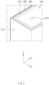
- FIG. 2 illustrates an enlarged view of a secondary battery according to an embodiment of the present invention when viewed in a diagonal direction (e.g., in a direction a).
- FIG. 2 is a perspective view of a secondary battery 100 when viewed in the direction a (e.g., in the diagonal direction from a Z-axis direction toward a Y-axis direction).
- the secondary battery 100 may include an electrode assembly 120 therein, and a pouch 110 may surround the electrode assembly 120.
- An accommodation part capable of accommodating the electrode assembly 120 may be formed in the secondary battery 100, and the electrode assembly 120 may be accommodated in the accommodation part.
- the pouch 110 may have a shape surrounding the electrode assembly 120 and/or the accommodation part.
- the pouch 110 may be formed of a plurality of pouches.
- the pouch 110 may include a first pouch 210, a second pouch 220, and a third pouch 230.
- the first pouch 210 may surround the electrode assembly 120 (or the accommodation part)
- the second pouch 220 may surround the first pouch 210
- the third pouch 230 may surround the second pouch 220.
- the pouch 110 at the outermost side may be termed the outermost pouch.
- the third pouch 230 may be the outermost pouch.
- the pouch 110 is formed of two pouches, one of which is the first pouch 210 surrounding the electrode assembly 120 (or the accommodation part) and the other of which is the second pouch 220 surrounding the first pouch 210, the second pouch 220 may be the outermost pouch.
- At least one hole (e.g., a hole 310) may be formed in the pouch 110.
- the at least one hole may be formed in each of the plurality of pouches.
- the plurality of pouches described above are three in number. However, this is an example, and the plurality of pouches may be two, or four or more in number.
- the same/similar explanation based on the assumption that the pouch 110 is formed of three pouches may also apply to the cases in which the pouch 110 is formed of two pouches and/or four or more pouches.
- FIG. 3 is a plan view of a secondary battery according to an embodiment of the present invention when viewed from above (e.g., in a direction b).
- FIG. 3 illustrates a secondary battery 100 when viewed in the direction b (e.g., a direction when viewed in the Z-axis direction).
- a hole 310 may be formed at one side of a pouch 110 (or a third pouch 230 that is the outermost pouch), and a hole 320 may be formed at the other side of the pouch 110 (or the third pouch 230 that is the outermost pouch).
- the positions of the hole 310 and the hole 320 illustrated in FIG. 3 are examples, and the hole 310 and the hole 320 may be formed in different positions according to a design.
- a line N-N' may be a folding line. Although an unfolded view is illustrated for convenience of explanation, the other side at which the hole 320 is formed may be folded on the basis of the line N-N' with respect to the one side at which the hole 310 is formed.
- the hole 310 and the hole 320 may be holes formed in the third pouch 230 that is the outermost pouch, and holes may be formed in not only the outermost pouch but also other pouches of the pouch 110.
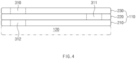
- FIG. 4 illustrates a structure of a plurality of pouches of a secondary battery according to an embodiment of the present invention.
- FIG. 4 illustrates a stacked structure of a pouch 110 formed of a plurality of pouches.
- the pouch 110 may include a plurality of pouches.
- the pouch 110 may surround an electrode assembly 120, and the plurality of pouches may surround the electrode assembly 120.
- an accommodation part capable of accommodating the electrode assembly 120 may be formed in a secondary battery 100, and the pouch 110 may have a shape surrounding the accommodation part.
- the pouch 110 may have a shape in which a first pouch 210 surrounds the electrode assembly 120 (or the accommodation part), a second pouch 220 surrounds the first pouch 210, and a third pouch 230 surrounds the second pouch 220.
- the stacked cross-sectional structure of the pouch 110 formed of three pouches may have a shape in which the second pouch 220 is stacked on the first pouch 210 and the third pouch 230 is stacked on the second pouch 220.
- the outermost pouch of the pouch 110 formed of three pouches may be the third pouch 230, and at least one hole 310 may be formed in the third pouch 230.
- At least one hole 312 may be formed in the first pouch 210, and at least one hole 311 may be formed also in the second pouch 220.
- the hole 311 of the second pouch 220 may not overlap the hole 312 of the first pouch 210 and/or the hole 310 of the third pouch 230.
- the hole 311 of the second pouch 220 may be misaligned with the hole 312 and the hole 310 and accordingly, an electrolyte inside the pouch 110 may not easily leak.
- the at least one hole (e.g., the hole 312, the hole 311, and the hole 310) is formed in each of the plurality of pouches (e.g., the first pouch 210, the second pouch 220, and the third pouch 230) so that when the pressure in the pouch 110 of the secondary battery 100 increases, gas may be discharged to the outside of the pouch 110 through the foregoing holes to decrease the internal pressure.
- the plurality of pouches e.g., the first pouch 210, the second pouch 220, and the third pouch 230
- the arrangement of the holes (e.g., the hole 310, the hole 311, and the hole 312), illustrated in FIG. 4 , is an example, and the arrangement of the holes may be different from the arrangement illustrated according to the design.
- FIG. 5 illustrates a side view of a secondary battery according to an embodiment when viewed from a side (e.g., in a direction c).
- FIG. 5 illustrates a secondary battery 100 when viewed in the direction c (e.g., the direction when viewed in the Y-axis direction).
- At least one hole may be formed at the other side of a pouch 110.
- a hole 320 and a hole 330 may be formed.
- the at least one holes may be formed in a third pouch 230 that is the outermost pouch.
- a spring part 410 may be coupled to the at least one holes (e.g., the hole 320 and the hole 330) formed in the pouch 110 (or the third pouch 230 that is the outermost pouch).
- the spring part 410 may have both ends, one of which is coupled to the hole 320 and the other of which is coupled to the hole 330.
- the spring part 410 may at least include a spring.
- the spring may have both ends, one of which is coupled to the hole 320 and the other of which is coupled to the hole 330.
- the spring part 410 may be coupled and fixed to the holes (e.g., the hole 320 and the hole 330).
- the both ends of the spring of the spring part 410 may be coupled to the holes (e.g., the hole 320 and the hole 330), respectively, in a hooking shape like a hook (e.g., hook-coupling) .
- the spring included in the spring part 410 may have an elastic force that is determined according to a characteristic of the spring (e.g., the material of the spring, the thickness of the spring, the length of the spring, etc.). For example, as an elastic modulus determined according to the material of the spring, the thickness of the spring, the length of the spring, etc., is higher, the elastic force may be higher.
- a characteristic of the spring e.g., the material of the spring, the thickness of the spring, the length of the spring, etc.
- the spring part 410 may be coupled to the holes (e.g., the hole 320 and the hole 330) and determine a degree of structural rigidity of the pouch 110. For example, when the spring part 410 includes a spring having a high elastic modulus, the higher elastic force may be secured compared to when including a spring having a low elastic modulus. As the elastic force of the spring part 410 increases, the degree of the structural rigidity of the pouch 110 may be determined to be high.
- FIG. 6 illustrates a secondary battery according to another embodiment of the present invention.
- a pouch 110 of a secondary battery 100 may not have a portion to be folded.
- the secondary battery 100 may include the pouch 110.
- the secondary battery 100 may include the pouch 110 including a plurality of pouches, and the pouch 110 may surround an electrode assembly (e.g., the electrode assembly 120) therein.
- an accommodation part capable of accommodating the electrode assembly 120 may be formed in the secondary battery 100, and the pouch 110 may have a shape surrounding the accommodation part.
- Each of the plurality of pouches may include an outer resin layer, an inner resin layer, and a thin metal layer disposed between the outer resin layer and the inner resin layer.
- the outermost pouch may be a third pouch 230.
- At least one hole may be formed in the pouch 110 (or the outermost pouch).
- a hole 340 and a hole 350 may be formed at one side of the pouch.
- the at least one hole formed in the pouch 110 is not limited by the one side of the pouch, and may be formed at the other side.
- the at least one hole is not limited by a surface at the one side, and may be formed in the other surfaces.
- a spring part 420 may be coupled to the at least one hole (e.g., the hole 340 and the hole 350) formed at the one side of the pouch 110.
- the spring part 420 may have both ends, one of which is coupled to the hole 340 and the other of which is coupled to the hole 350.
- the spring part 420 may include a spring, and the spring may have both ends, one of which is coupled to the hole 340 and the other of which is coupled to the hole 350.
- the spring part 420 or the spring included in the spring part 420 may be coupled to the holes (e.g., the hole 340 and the hole 350) in a hooking shape like a hook (e.g., hook-coupling).
- the spring included in the spring part 420 may have an elastic force that is determined according to a characteristic of the spring (e.g., the material of the spring, the thickness of the spring, the length of the spring, etc.). For example, as an elastic modulus determined according to the material of the spring, the thickness of the spring, the length of the spring, etc., is higher, the elastic force is higher.
- a characteristic of the spring e.g., the material of the spring, the thickness of the spring, the length of the spring, etc.
- the spring part 420 may be coupled to the holes (e.g., the hole 340 and the hole 350) and determine a degree of structural rigidity of the pouch 110. For example, when the spring part 420 includes a spring having a high elastic modulus, the higher elastic force may be secured compared to when including a spring having a low elastic modulus. As the elastic force of the spring part 420 increases, the degree of the structural rigidity of the pouch 110 may be determined to be high.
- FIG. 7 illustrates a secondary battery according to further another embodiment of the present invention.
- An electrode assembly (e.g., the electrode assembly 120) may be accommodated in a secondary battery 100.
- an accommodation part capable of accommodating the electrode assembly 120 may be formed in the secondary battery 100, and the electrode assembly 120 may be accommodated in the accommodation part.
- the secondary battery 100 may include a pouch 110.
- the pouch 110 may surround the electrode assembly (e.g., the electrode assembly 120) or the accommodation part in the secondary battery 100.
- the pouch 110 may be formed of a plurality of pouches.
- the plurality of pouches may surround the electrode assembly (e.g., the electrode assembly 120) or the accommodation part in the secondary battery 100.
- each of the plurality of pouches may include an outer resin layer, an inner resin layer, and a thin metal layer disposed between the outer resin layer and the inner resin layer.
- the pouch 110 may seal the electrode assembly (e.g., the electrode assembly 120) or the accommodation part.
- the pouch 110 may have a shape surrounding the electrode assembly (e.g., the electrode assembly 120) or the accommodation part, and accordingly, the electrode assembly (e.g., the electrode assembly 120) or the accommodation part may be sealed.
- an open portion may be formed in the outermost pouch of the plurality of pouches.
- an open portion 360 may be formed at one side of the outermost pouch (e.g., the third pouch 230).
- the open portion 360 may be formed in a longitudinal direction of the outermost pouch (e.g., the third pouch 230). The open portion 360 may pass through a portion of the one side of the outermost pouch (e.g., the third pouch 230) .
- the open portion 360 may have both ends to which a spring part 430 is coupled.
- the spring part 430 may be coupled to the both ends of the open portion 360, and determine a degree of structural rigidity of the outermost pouch (e.g., the third pouch 230).
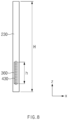
- FIG. 8 illustrates a side view of a secondary battery according to further another embodiment of the present invention when viewed from a side (e.g., in a direction d) .
- FIG. 8 illustrates a side surface of a pouch 110 of a secondary battery 100 in the direction d (e.g., a direction from a negative (-) Y-axis direction to a positive (+) Y-axis direction).
- An open portion may be formed at one side of the outermost pouch (e.g., the third pouch 230) of the pouch 110.
- an open portion 360 may be formed in a longitudinal direction of the one side of the outermost pouch (e.g., the third pouch 230).
- the open portion 360 may have a length that is 1/3 or less of the length of the one side of the outermost pouch (e.g., the third pouch 230).
- the open portion 360 may have a length h that is 1/3H or less.
- the open portion 360 may have both ends to which a spring part 430 is coupled.
- one end of the spring part 430 may be coupled to one end of the open portion 360, and the other end of the spring part 430 may be coupled to the other end of the open portion 360.
- the spring part 340 may include a spring.
- the spring of the spring part 430 may have one end coupled to the one end of the open portion 360, and the other end coupled to the other end of the open portion 360.
- a degree of structural rigidity of the pouch 110 may be determined based on an elastic force determined according to a characteristic of the spring part 430 or the spring included in the spring part 430.
- the elastic force of the spring included in the spring part 420 may be determined according to the characteristic of the spring (e.g., the material of the spring, the thickness of the spring, the length of the spring, etc.). For example, as an elastic modulus determined according to the material of the spring, the thickness of the spring, the length of the spring, etc., is higher, the elastic force be higher.
- the spring part 430 may be coupled to the open portion 360 and determine the degree of the structural rigidity of the pouch 110. For example, when the spring part 430 includes a spring having a high elastic modulus, the higher elastic force may be secured compared to when including a spring having a low elastic modulus. As the elastic force of the spring part 430 or the spring increases, the degree of the structural rigidity of the pouch 110 may be determined to be high.
Landscapes
- Chemical & Material Sciences (AREA)
- Chemical Kinetics & Catalysis (AREA)
- Electrochemistry (AREA)
- General Chemical & Material Sciences (AREA)
- Inorganic Chemistry (AREA)
- Engineering & Computer Science (AREA)
- Manufacturing & Machinery (AREA)
- Sealing Battery Cases Or Jackets (AREA)
- Secondary Cells (AREA)
- Battery Mounting, Suspending (AREA)
Abstract
Description
- The present application claims the benefit of the priority of
Korean Patent Application No. 10-2021-0149043, filed on November 02, 2021 - The present disclosure relates to a pouch for a secondary battery formed of a plurality of pouches, and a secondary battery including the pouch.
- With an increasing need for alternative energy, research into techniques and development for power generation technologies based on energy sources such as solar heat, water power, wind power, ocean energy, and biomass energy, which have little impact on the environmental pollution, are carried out. In particular, research on secondary batteries that can be repeatedly charged are actively carried out, and development is carried out on aspects such as the materials, efficiency, structures, stability, and systems of the secondary batteries.
- Various types of secondary batteries, such as a pouch type, a prismatic type, and a cylindrical type, are applied to electronic systems such as vehicles, mobile phones, and notebook computers. The electronic systems may be packed/sealed and utilized according to packing/sealing methods corresponding to the types, respectively. In the aspects of the structural rigidity and stability of the electronic systems to which the secondary batteries are applied, management of packing and sealing the secondary batteries is necessary, and structures for packing and sealing are proposed.
- In the case of the pouch type secondary batteries, there are proposals for various methods and structures for sealing a plurality of regions of a pouch for the management of sealing the secondary batteries, and there are proposals for degassing methods and devices for internal pressure management of the secondary batteries.
- According to the related art, in the case of the pouch type secondary batteries, a degree of rigidity of the pouch is difficult to determine or adjust and thus, structural rigidity may be difficult to manage when defects occur in battery management systems or during the packing.
- According to the related art, when the internal pressure increases during utilizing the secondary batteries in the electronic systems, it may be difficult to adaptively maintain the degree of structural rigidity of the pouch against the increase in internal pressure of the secondary batteries.
- The present invention for resolving the above problems provides a pouch for a secondary battery, to which a structure capable of variously establishing a degree of structural rigidity and adapting to a change in internal pressure is applied to make management of sealing and internal pressure easier, and a secondary battery including the pouch.
- A pouch for a secondary battery according to the present invention may include: a plurality of pouches that accommodate an electrode assembly; and a spring part that is coupled to the outermost pouch of the plurality of pouches and determines a degree of structural rigidity of the outermost pouch.
- At least one hole may be formed in the outermost pouch, and the spring part may be coupled to the at least one hole.
- Each of the plurality of pouches may include an outer resin layer, an inner resin layer, and a thin metal layer disposed between the outer resin layer and the inner resin layer.
- At least one hole may be formed in each of the plurality of pouches.
- A hole formed in one pouch of the plurality of pouches may not overlap a hole formed in another pouch surrounding the one pouch.
- The spring part may include a spring, and the spring part may determine the degree of the structural rigidity on the basis of an elastic force determined according to a characteristic of the spring.
- The characteristic may be at least one of a spring material, a spring thickness, or a spring length, and the elastic force may be determined by a change of at least one of the spring material, the spring thickness, or the spring length.
- A secondary battery according to the present invention may include: an electrode assembly in which an electrode and a separator are stacked alternately; a plurality of pouches that surround the electrode assembly and seal the electrode assembly; and a spring part that is coupled to the outermost pouch of the plurality of pouches and determines a degree of the structural rigidity of the outermost pouch.
- A pouch for a secondary battery according to the present invention may include: a plurality of pouches that accommodate an electrode assembly; an open portion formed at one side of the outermost pouch of the plurality of pouches and passing through a portion of the one side; and a spring part that is coupled to both ends of the open portion and determines a degree of structural rigidity of the outermost pouch.
- The open portion may be formed in a circumferential direction of the one side and have a length that is 1/3 or less of a length of the one side.
- The spring part may include a spring, and the spring part may determine the degree of the structural rigidity on the basis of an elastic force determined according to a characteristic of the spring.
- The characteristic may be at least one of a spring material, a spring thickness, or a spring length, and the elastic force may be determined by a change of at least one of the spring material, the spring thickness, or the spring length.
- A secondary battery according to the present invention may include: an electrode assembly in which an electrode and a separator are stacked alternately; a plurality of pouches that surround the electrode assembly and seal the electrode assembly; an open portion formed at one side of the outermost pouch of the plurality of pouches and passing through a portion of the one side; and a spring part that is coupled to both ends of the open portion and determines a degree of structural rigidity of the outermost pouch.
- According to the present invention, the structure in which the plurality of pouches surround the electrode assembly may be proposed to improve the degree of the fundamental structural rigidity of the secondary battery.
- According to the present invention, the spring part capable of determining the degree of the structural rigidity may be coupled to the outermost pouch of the plurality of pouches and accordingly, the adaptability to the degree of the structural rigidity of the secondary battery may be improved.
- According to the present invention, the holes may be formed in each of the plurality of pouches and accordingly, the management of the internal pressure and the electrolyte of the secondary battery may be easier.
- According to the present invention, the stable structural rigidity may be provided by the pouch itself even when the defects exist in the secondary battery management system or the packing itself.
-
-
FIG. 1 is a view illustrating a secondary battery according to an embodiment of the present invention. -
FIG. 2 is an enlarged view of a secondary battery according to an embodiment of the present invention when viewed in a diagonal direction (e.g., in a direction a). -
FIG. 3 is a plan view of a secondary battery according to an embodiment of the present invention when viewed from above (e.g., in a direction b). -
FIG. 4 is a view illustrating a structure of a plurality of pouches of a secondary battery according to an embodiment of the present invention. -
FIG. 5 is a side view of a secondary battery according to an embodiment when viewed from a side (e.g., in a direction c) . -
FIG. 6 is a view illustrating a secondary battery according to another embodiment of the present invention. -
FIG. 7 is a view illustrating a secondary battery according to further another embodiment of the present invention. -
FIG. 8 is a side view of a secondary battery according to further another embodiment of the present invention when viewed from a side (e.g., in a direction d). - Hereinafter, preferred embodiments of the present invention will be described in detail with reference to the accompanying drawings to enable those skilled in the art to which the present invention pertains to easily carry out the present invention. The present invention may, however, be embodied in different forms and should not be construed as limited by the embodiments set forth herein.
- The parts unrelated to the description, or the detailed descriptions of related well-known art that may unnecessarily obscure subject matters of the present invention, will be ruled out in order to clearly describe the present invention. Like reference numerals refer to like elements throughout the whole specification.
- Moreover, terms or words used in this specification and claims should not be restrictively interpreted as ordinary meanings or dictionary-based meanings, but should be interpreted as meanings and concepts conforming to the scope of the present invention on the basis of the principle that an inventor can properly define the concept of a term to describe and explain his or her invention in the best ways.
-
FIG. 1 illustrates a secondary battery according to an embodiment of the present invention. - A
secondary battery 100 may include anelectrode assembly 120 therein, which is formed by stacking an electrode and a separator alternately. - The
secondary battery 100 may include apouch 110. For example, thepouch 110 may form an outer appearance of thesecondary battery 100. For another example, thepouch 110 may include a plurality of pouches. - The
pouch 110 may surround theelectrode assembly 120 in thesecondary battery 100. For example, thepouch 110 may seal theelectrode assembly 120 while surrounding theelectrode assembly 120. For another example, an accommodation part capable of accommodating theelectrode assembly 120 may be formed in thesecondary battery 100, and thepouch 110 may seal the accommodation part (or theelectrode assembly 120 accommodated in the accommodation part) in a shape surrounding the accommodation part. - The
pouch 110 may be formed of the plurality of pouches, and the plurality of pouches may surround theelectrode assembly 120. The plurality of pouches may seal theelectrode assembly 120 while surrounding theelectrode assembly 120. The plurality of pouches may seal theelectrode assembly 120 while sequentially surrounding the electrode assembly 120 (or the accommodation part). - The
pouch 110 may include an outer resin layer, an inner resin layer, and a thin metal layer disposed between the outer resin layer and the inner resin layer. When thepouch 110 are formed of the plurality of pouches, the plurality of pouches may each include the outer resin layer, the inner resin layer, and the thin metal layer disposed between the outer resin layer and the inner resin layer. - At least one hole for discharging gas generated in the
electrode assembly 120 or adjusting internal pressure may be formed in thepouch 110. - When the
pouch 110 are formed of the plurality of pouches, the at least one hole may be formed in each of the plurality of pouches. - A spring part configured to adjust a degree of structural rigidity (or sealing force) of the
pouch 110 may be coupled to the at least one hole formed in thepouch 110. -
FIG. 2 illustrates an enlarged view of a secondary battery according to an embodiment of the present invention when viewed in a diagonal direction (e.g., in a direction a).FIG. 2 is a perspective view of asecondary battery 100 when viewed in the direction a (e.g., in the diagonal direction from a Z-axis direction toward a Y-axis direction). - The
secondary battery 100 may include anelectrode assembly 120 therein, and apouch 110 may surround theelectrode assembly 120. - An accommodation part capable of accommodating the
electrode assembly 120 may be formed in thesecondary battery 100, and theelectrode assembly 120 may be accommodated in the accommodation part. - The
pouch 110 may have a shape surrounding theelectrode assembly 120 and/or the accommodation part. - The
pouch 110 may be formed of a plurality of pouches. For example, thepouch 110 may include afirst pouch 210, asecond pouch 220, and athird pouch 230. For a specific example, thefirst pouch 210 may surround the electrode assembly 120 (or the accommodation part), thesecond pouch 220 may surround thefirst pouch 210, and thethird pouch 230 may surround thesecond pouch 220. - When the
pouch 110 is formed of the plurality of pouches, thepouch 110 at the outermost side may be termed the outermost pouch. For example, when thefirst pouch 210 surrounds theelectrode assembly 120, and thesecond pouch 220 surrounds thefirst pouch 210, and thethird pouch 230 surrounds thesecond pouch 220, thethird pouch 230 may be the outermost pouch. For another example, when thepouch 110 is formed of two pouches, one of which is thefirst pouch 210 surrounding the electrode assembly 120 (or the accommodation part) and the other of which is thesecond pouch 220 surrounding thefirst pouch 210, thesecond pouch 220 may be the outermost pouch. - At least one hole (e.g., a hole 310) may be formed in the
pouch 110. When thepouch 110 is formed of the plurality of pouches, the at least one hole may be formed in each of the plurality of pouches. - The plurality of pouches described above are three in number. However, this is an example, and the plurality of pouches may be two, or four or more in number.
- The same/similar explanation based on the assumption that the
pouch 110 is formed of three pouches may also apply to the cases in which thepouch 110 is formed of two pouches and/or four or more pouches. -
FIG. 3 is a plan view of a secondary battery according to an embodiment of the present invention when viewed from above (e.g., in a direction b).FIG. 3 illustrates asecondary battery 100 when viewed in the direction b (e.g., a direction when viewed in the Z-axis direction). - A
hole 310 may be formed at one side of a pouch 110 (or athird pouch 230 that is the outermost pouch), and ahole 320 may be formed at the other side of the pouch 110 (or thethird pouch 230 that is the outermost pouch). The positions of thehole 310 and thehole 320 illustrated inFIG. 3 are examples, and thehole 310 and thehole 320 may be formed in different positions according to a design. - Referring to
FIG. 3 , a line N-N' may be a folding line. Although an unfolded view is illustrated for convenience of explanation, the other side at which thehole 320 is formed may be folded on the basis of the line N-N' with respect to the one side at which thehole 310 is formed. - The
hole 310 and thehole 320 may be holes formed in thethird pouch 230 that is the outermost pouch, and holes may be formed in not only the outermost pouch but also other pouches of thepouch 110. -
FIG. 4 illustrates a structure of a plurality of pouches of a secondary battery according to an embodiment of the present invention.FIG. 4 illustrates a stacked structure of apouch 110 formed of a plurality of pouches. - The
pouch 110 may include a plurality of pouches. For example, thepouch 110 may surround anelectrode assembly 120, and the plurality of pouches may surround theelectrode assembly 120. For another example, an accommodation part capable of accommodating theelectrode assembly 120 may be formed in asecondary battery 100, and thepouch 110 may have a shape surrounding the accommodation part. - When the
pouch 110 is formed of three pouches, thepouch 110 may have a shape in which afirst pouch 210 surrounds the electrode assembly 120 (or the accommodation part), asecond pouch 220 surrounds thefirst pouch 210, and athird pouch 230 surrounds thesecond pouch 220. - As illustrated in
FIG. 4 , the stacked cross-sectional structure of thepouch 110 formed of three pouches may have a shape in which thesecond pouch 220 is stacked on thefirst pouch 210 and thethird pouch 230 is stacked on thesecond pouch 220. - The outermost pouch of the
pouch 110 formed of three pouches may be thethird pouch 230, and at least onehole 310 may be formed in thethird pouch 230. - At least one
hole 312 may be formed in thefirst pouch 210, and at least onehole 311 may be formed also in thesecond pouch 220. - The
hole 311 of thesecond pouch 220 may not overlap thehole 312 of thefirst pouch 210 and/or thehole 310 of thethird pouch 230. For example, thehole 311 of thesecond pouch 220 may be misaligned with thehole 312 and thehole 310 and accordingly, an electrolyte inside thepouch 110 may not easily leak. - The at least one hole (e.g., the
hole 312, thehole 311, and the hole 310) is formed in each of the plurality of pouches (e.g., thefirst pouch 210, thesecond pouch 220, and the third pouch 230) so that when the pressure in thepouch 110 of thesecondary battery 100 increases, gas may be discharged to the outside of thepouch 110 through the foregoing holes to decrease the internal pressure. - The arrangement of the holes (e.g., the
hole 310, thehole 311, and the hole 312), illustrated inFIG. 4 , is an example, and the arrangement of the holes may be different from the arrangement illustrated according to the design. -
FIG. 5 illustrates a side view of a secondary battery according to an embodiment when viewed from a side (e.g., in a direction c).FIG. 5 illustrates asecondary battery 100 when viewed in the direction c (e.g., the direction when viewed in the Y-axis direction). - At least one hole may be formed at the other side of a
pouch 110. For example, ahole 320 and ahole 330 may be formed. - When the
pouch 110 is formed of three pouches, the at least one holes (e.g., thehole 320 and the hole 330) may be formed in athird pouch 230 that is the outermost pouch. - A
spring part 410 may be coupled to the at least one holes (e.g., thehole 320 and the hole 330) formed in the pouch 110 (or thethird pouch 230 that is the outermost pouch). For example, thespring part 410 may have both ends, one of which is coupled to thehole 320 and the other of which is coupled to thehole 330. - The
spring part 410 may at least include a spring. The spring may have both ends, one of which is coupled to thehole 320 and the other of which is coupled to thehole 330. For example, thespring part 410 may be coupled and fixed to the holes (e.g., thehole 320 and the hole 330). For another example, the both ends of the spring of thespring part 410 may be coupled to the holes (e.g., thehole 320 and the hole 330), respectively, in a hooking shape like a hook (e.g., hook-coupling) . - The spring included in the
spring part 410 may have an elastic force that is determined according to a characteristic of the spring (e.g., the material of the spring, the thickness of the spring, the length of the spring, etc.). For example, as an elastic modulus determined according to the material of the spring, the thickness of the spring, the length of the spring, etc., is higher, the elastic force may be higher. - The
spring part 410 may be coupled to the holes (e.g., thehole 320 and the hole 330) and determine a degree of structural rigidity of thepouch 110. For example, when thespring part 410 includes a spring having a high elastic modulus, the higher elastic force may be secured compared to when including a spring having a low elastic modulus. As the elastic force of thespring part 410 increases, the degree of the structural rigidity of thepouch 110 may be determined to be high. -
FIG. 6 illustrates a secondary battery according to another embodiment of the present invention. - A
pouch 110 of asecondary battery 100 according to another embodiment may not have a portion to be folded. - The
secondary battery 100 may include thepouch 110. For example, thesecondary battery 100 may include thepouch 110 including a plurality of pouches, and thepouch 110 may surround an electrode assembly (e.g., the electrode assembly 120) therein. For another example, an accommodation part capable of accommodating theelectrode assembly 120 may be formed in thesecondary battery 100, and thepouch 110 may have a shape surrounding the accommodation part. Each of the plurality of pouches may include an outer resin layer, an inner resin layer, and a thin metal layer disposed between the outer resin layer and the inner resin layer. - When the
pouch 110 is formed of three pouches, the outermost pouch may be athird pouch 230. - At least one hole may be formed in the pouch 110 (or the outermost pouch). For example, a
hole 340 and a hole 350 may be formed at one side of the pouch. - The at least one hole formed in the
pouch 110 is not limited by the one side of the pouch, and may be formed at the other side. For example, when thepouch 110 has a plurality of surfaces, the at least one hole is not limited by a surface at the one side, and may be formed in the other surfaces. - A
spring part 420 may be coupled to the at least one hole (e.g., thehole 340 and the hole 350) formed at the one side of thepouch 110. For example, thespring part 420 may have both ends, one of which is coupled to thehole 340 and the other of which is coupled to the hole 350. For another example, thespring part 420 may include a spring, and the spring may have both ends, one of which is coupled to thehole 340 and the other of which is coupled to the hole 350. Thespring part 420 or the spring included in thespring part 420 may be coupled to the holes (e.g., thehole 340 and the hole 350) in a hooking shape like a hook (e.g., hook-coupling). - The spring included in the
spring part 420 may have an elastic force that is determined according to a characteristic of the spring (e.g., the material of the spring, the thickness of the spring, the length of the spring, etc.). For example, as an elastic modulus determined according to the material of the spring, the thickness of the spring, the length of the spring, etc., is higher, the elastic force is higher. - The
spring part 420 may be coupled to the holes (e.g., thehole 340 and the hole 350) and determine a degree of structural rigidity of thepouch 110. For example, when thespring part 420 includes a spring having a high elastic modulus, the higher elastic force may be secured compared to when including a spring having a low elastic modulus. As the elastic force of thespring part 420 increases, the degree of the structural rigidity of thepouch 110 may be determined to be high. -
FIG. 7 illustrates a secondary battery according to further another embodiment of the present invention. - An electrode assembly (e.g., the electrode assembly 120) may be accommodated in a
secondary battery 100. For example, an accommodation part capable of accommodating theelectrode assembly 120 may be formed in thesecondary battery 100, and theelectrode assembly 120 may be accommodated in the accommodation part. - The
secondary battery 100 may include apouch 110. For example, thepouch 110 may surround the electrode assembly (e.g., the electrode assembly 120) or the accommodation part in thesecondary battery 100. - The
pouch 110 may be formed of a plurality of pouches. For example, the plurality of pouches may surround the electrode assembly (e.g., the electrode assembly 120) or the accommodation part in thesecondary battery 100. For another example, each of the plurality of pouches may include an outer resin layer, an inner resin layer, and a thin metal layer disposed between the outer resin layer and the inner resin layer. - The pouch 110 (or the plurality of pouches) may seal the electrode assembly (e.g., the electrode assembly 120) or the accommodation part. For example, the pouch 110 (or the plurality of pouches) may have a shape surrounding the electrode assembly (e.g., the electrode assembly 120) or the accommodation part, and accordingly, the electrode assembly (e.g., the electrode assembly 120) or the accommodation part may be sealed.
- When the
pouch 110 is formed of the plurality of pouches, an open portion may be formed in the outermost pouch of the plurality of pouches. For example, when thepouch 110 is formed of three pouches, anopen portion 360 may be formed at one side of the outermost pouch (e.g., the third pouch 230). For another example, theopen portion 360 may be formed in a longitudinal direction of the outermost pouch (e.g., the third pouch 230). Theopen portion 360 may pass through a portion of the one side of the outermost pouch (e.g., the third pouch 230) . - The
open portion 360 may have both ends to which aspring part 430 is coupled. For example, thespring part 430 may be coupled to the both ends of theopen portion 360, and determine a degree of structural rigidity of the outermost pouch (e.g., the third pouch 230). -
FIG. 8 illustrates a side view of a secondary battery according to further another embodiment of the present invention when viewed from a side (e.g., in a direction d) .FIG. 8 illustrates a side surface of apouch 110 of asecondary battery 100 in the direction d (e.g., a direction from a negative (-) Y-axis direction to a positive (+) Y-axis direction). - An open portion may be formed at one side of the outermost pouch (e.g., the third pouch 230) of the
pouch 110. For example, anopen portion 360 may be formed in a longitudinal direction of the one side of the outermost pouch (e.g., the third pouch 230). - The
open portion 360 may have a length that is 1/3 or less of the length of the one side of the outermost pouch (e.g., the third pouch 230). For example, when the one side of the outermost pouch (e.g., the third pouch 230) has a length H, theopen portion 360 may have a length h that is 1/3H or less. - The
open portion 360 may have both ends to which aspring part 430 is coupled. For example, one end of thespring part 430 may be coupled to one end of theopen portion 360, and the other end of thespring part 430 may be coupled to the other end of theopen portion 360. - The
spring part 340 may include a spring. - The spring of the
spring part 430 may have one end coupled to the one end of theopen portion 360, and the other end coupled to the other end of theopen portion 360. - A degree of structural rigidity of the pouch 110 (or the outermost pouch 230) may be determined based on an elastic force determined according to a characteristic of the
spring part 430 or the spring included in thespring part 430. For example, the elastic force of the spring included in thespring part 420 may be determined according to the characteristic of the spring (e.g., the material of the spring, the thickness of the spring, the length of the spring, etc.). For example, as an elastic modulus determined according to the material of the spring, the thickness of the spring, the length of the spring, etc., is higher, the elastic force be higher. - The
spring part 430 may be coupled to theopen portion 360 and determine the degree of the structural rigidity of thepouch 110. For example, when thespring part 430 includes a spring having a high elastic modulus, the higher elastic force may be secured compared to when including a spring having a low elastic modulus. As the elastic force of thespring part 430 or the spring increases, the degree of the structural rigidity of thepouch 110 may be determined to be high. - Although the present invention has been described with reference to the limited embodiments and drawings, the present invention is not limited thereto and may be variously implemented by those of ordinary skill in the art to which the present invention pertains, within the technical idea of the present invention and an equivalent of the appended claims.
-
- 100:
- Secondary battery
- 110:
- A plurality of pouches
- 120:
- Electrode assembly
- 210:
- First pouch
- 220:
- Second pouch
- 230:
- Third pouch
- 310:
- Outermost hole
- 311:
- Hole
- 312:
- Hole
- 320:
- Outermost hole
- 330:
- Outermost hole
- 340:
- Outermost hole
- 350:
- Outermost hole
- 360:
- Open portion
- 410:
- Spring part
- 420:
- Spring part
- 430:
- Spring part
Claims (13)
- A pouch for a secondary battery, comprising:a plurality of pouches configured to accommodate an electrode assembly; anda spring part coupled to the outermost pouch of the plurality of pouches and configured to determine a degree of structural rigidity of the outermost pouch.
- The pouch for a secondary battery of claim 1, wherein at least one hole is formed in the outermost pouch, and
the spring part is coupled to the at least one hole. - The pouch for a secondary battery of claim 1, wherein each of the plurality of pouches comprises an outer resin layer, an inner resin layer, and a thin metal layer disposed between the outer resin layer and the inner resin layer.
- The pouch for a secondary battery of claim 1, wherein at least one hole is formed in each of the plurality of pouches.
- The pouch for a secondary battery of claim 4, wherein a hole formed in one pouch of the plurality of pouches does not overlap a hole formed in another pouch surrounding the one pouch.
- The pouch for a secondary battery of claim 1, wherein the spring part comprises a spring, and
the spring part determines the degree of the structural rigidity on the basis of an elastic force determined according to a characteristic of the spring. - The pouch for a secondary battery of claim 6, wherein the characteristic is at least one of a spring material, a spring thickness, or a spring length, and
the elastic force is determined by a change of at least one of the spring material, the spring thickness, or the spring length. - A secondary battery comprising:an electrode assembly in which an electrode and a separator are stacked alternately;a plurality of pouches configured to surround the electrode assembly and seal the electrode assembly; anda spring part coupled to the outermost pouch of the plurality of pouches and configured to determine a degree of structural rigidity of the outermost pouch.
- A pouch for a secondary battery, comprising:a plurality of pouches configured to accommodate an electrode assembly;an open portion formed at one side of the outermost pouch of the plurality of pouches and passing through a portion of the one side; anda spring part coupled to both ends of the open portion and configured to determine a degree of structural rigidity of the outermost pouch.
- The pouch for a secondary battery of claim 9, wherein the open portion is formed in a circumferential direction of the one side and has a length that is 1/3 or less of a length of the one side.
- The pouch for a secondary battery of claim 9, wherein the spring part comprises a spring, and
the spring part determines the degree of the structural rigidity on the basis of an elastic force determined according to a characteristic of the spring. - The pouch for a secondary battery of claim 11, wherein the characteristic is at least one of a spring material, a spring thickness, or a spring length, and
the elastic force is determined by a change of at least one of the spring material, the spring thickness, or the spring length. - A secondary battery comprising:an electrode assembly in which an electrode and a separator are stacked alternately;a plurality of pouches configured to surround the electrode assembly and seal the electrode assembly;an open portion formed at one side of the outermost pouch of the plurality of pouches and passing through a portion of the one side; anda spring part coupled to both ends of the open portion and configured to determine a degree of structural rigidity of the outermost pouch.
Applications Claiming Priority (2)
| Application Number | Priority Date | Filing Date | Title |
|---|---|---|---|
| KR1020210149043A KR102921534B1 (en) | 2021-11-02 | 2021-11-02 | Pouch for secondary battery formed of plurality of pouches and secondary battery including the same |
| PCT/KR2022/016345 WO2023080518A1 (en) | 2021-11-02 | 2022-10-25 | Secondary battery pouch having plurality of pouches and secondary battery including same |
Publications (2)
| Publication Number | Publication Date |
|---|---|
| EP4372873A1 true EP4372873A1 (en) | 2024-05-22 |
| EP4372873A4 EP4372873A4 (en) | 2025-01-15 |
Family
ID=86241414
Family Applications (1)
| Application Number | Title | Priority Date | Filing Date |
|---|---|---|---|
| EP22890253.2A Pending EP4372873A4 (en) | 2021-11-02 | 2022-10-25 | SECONDARY BATTERY BAG COMPRISING A PLURALITY OF BAGS AND SECONDARY BATTERY COMPRISING SAME |
Country Status (6)
| Country | Link |
|---|---|
| US (1) | US20240194985A1 (en) |
| EP (1) | EP4372873A4 (en) |
| JP (1) | JP7601464B2 (en) |
| KR (1) | KR102921534B1 (en) |
| CN (1) | CN117916930A (en) |
| WO (1) | WO2023080518A1 (en) |
Family Cites Families (17)
| Publication number | Priority date | Publication date | Assignee | Title |
|---|---|---|---|---|
| JP2005197179A (en) * | 2004-01-09 | 2005-07-21 | Toyota Motor Corp | Single cells and batteries |
| JP4604535B2 (en) * | 2004-03-30 | 2011-01-05 | トヨタ自動車株式会社 | Laminated secondary battery |
| JP2007035469A (en) * | 2005-07-27 | 2007-02-08 | Kojima Press Co Ltd | Battery case |
| KR101452001B1 (en) * | 2009-10-09 | 2014-10-23 | 주식회사 엘지화학 | Method for manufacturing pouch type secondary battery and pouch type secondary battery |
| KR101040875B1 (en) * | 2009-12-31 | 2011-06-16 | 삼성에스디아이 주식회사 | Secondary battery |
| KR101505722B1 (en) * | 2012-04-09 | 2015-03-25 | 주식회사 엘지화학 | Lithium secondary battery comprising elastic clip device and method for preparation the same |
| KR101972601B1 (en) * | 2012-11-23 | 2019-04-25 | 에스케이이노베이션 주식회사 | Frame in secondary battery pouch and Secondary battery having the frame |
| KR20140133218A (en) * | 2013-05-10 | 2014-11-19 | 주식회사 엘지화학 | Double Pouch for secondary battery having improved safety and secondary battery using the same |
| JP2016010911A (en) * | 2014-06-30 | 2016-01-21 | 京セラドキュメントソリューションズ株式会社 | Ink container and inkjet recording device comprising the same |
| JP6488812B2 (en) * | 2015-03-25 | 2019-03-27 | 株式会社豊田自動織機 | Battery module |
| EP3220467B1 (en) | 2015-07-27 | 2024-10-30 | LG Energy Solution, Ltd. | Pouch type secondary battery comprising safety member |
| KR102522705B1 (en) * | 2017-07-04 | 2023-04-18 | 주식회사 엘지에너지솔루션 | Secondary Battery |
| MX2021012516A (en) | 2019-04-19 | 2021-11-12 | Bytedance Inc | Context coding for transform skip mode. |
| KR102396437B1 (en) * | 2019-06-25 | 2022-05-09 | 주식회사 엘지에너지솔루션 | Battery module and battery pack including the same |
| WO2021168746A1 (en) * | 2020-02-27 | 2021-09-02 | 宁德新能源科技有限公司 | Battery, electrochemical apparatus, and electronic device |
| KR102900642B1 (en) * | 2020-04-10 | 2025-12-15 | 주식회사 엘지에너지솔루션 | Battery cell for evaluating the lithium-plating and its manufacturing method |
| DE102020126752A1 (en) | 2020-10-12 | 2022-04-14 | Volkswagen Aktiengesellschaft | battery arrangement |
-
2021
- 2021-11-02 KR KR1020210149043A patent/KR102921534B1/en active Active
-
2022
- 2022-10-25 WO PCT/KR2022/016345 patent/WO2023080518A1/en not_active Ceased
- 2022-10-25 JP JP2023568389A patent/JP7601464B2/en active Active
- 2022-10-25 EP EP22890253.2A patent/EP4372873A4/en active Pending
- 2022-10-25 CN CN202280057132.0A patent/CN117916930A/en active Pending
-
2024
- 2024-02-21 US US18/583,402 patent/US20240194985A1/en active Pending
Also Published As
| Publication number | Publication date |
|---|---|
| KR102921534B1 (en) | 2026-02-03 |
| EP4372873A4 (en) | 2025-01-15 |
| CN117916930A (en) | 2024-04-19 |
| JP7601464B2 (en) | 2024-12-17 |
| KR20230063696A (en) | 2023-05-09 |
| WO2023080518A1 (en) | 2023-05-11 |
| JP2024517275A (en) | 2024-04-19 |
| US20240194985A1 (en) | 2024-06-13 |
Similar Documents
| Publication | Publication Date | Title |
|---|---|---|
| EP3651227B1 (en) | Pouch-shaped battery case having hidden-type gas pocket, pouch-shaped secondary battery including the same, and battery module including the same | |
| EP3739666B1 (en) | Pouch-type battery cell comprising venting member and battery pack comprising the same | |
| CN109417151B (en) | Battery cells using bus bars | |
| US12586858B2 (en) | Battery, electric device, method for manufacturing battery, and device for manufacturing battery | |
| KR20170019332A (en) | Pouch-Typed Battery Cell Having Ring Shape | |
| US20230122619A1 (en) | Battery cell, battery, power consumption device, and manufaturing method and device of battery cell | |
| EP3745488A1 (en) | Pouch-type secondary battery and battery module comprising the same | |
| CN116457976B (en) | Secondary battery and device including the secondary battery | |
| US20030129483A1 (en) | Battery and method of packaging | |
| EP4138189A1 (en) | Secondary battery module and method for manufacturing same | |
| US20240194985A1 (en) | Pouch for Secondary Battery Formed of Multiple Pouches, and Secondary Battery Including the Same | |
| EP4564548A1 (en) | Battery cap assembly including same, and battery cell including same | |
| US20030129488A1 (en) | Planar battery and method of sealing | |
| EP4525158A1 (en) | Battery module | |
| EP4401219A1 (en) | Battery module for preventing battery rupture | |
| KR20210064779A (en) | Secondary battery | |
| US20250132445A1 (en) | Battery module | |
| EP4507098A1 (en) | Battery pack | |
| EP4654358A1 (en) | Battery cell, battery, and electric device | |
| US20250379262A1 (en) | Battery cell, battery, and power consuming apparatus | |
| EP4366071A1 (en) | Current collecting component, battery, and battery module | |
| US20250210834A1 (en) | Secondary battery with electrolyte injection port | |
| EP4632856A1 (en) | Secondary battery | |
| EP4386945A1 (en) | Rectangular lithium ion secondary battery | |
| US20250293392A1 (en) | Battery module |
Legal Events
| Date | Code | Title | Description |
|---|---|---|---|
| STAA | Information on the status of an ep patent application or granted ep patent |
Free format text: STATUS: THE INTERNATIONAL PUBLICATION HAS BEEN MADE |
|
| PUAI | Public reference made under article 153(3) epc to a published international application that has entered the european phase |
Free format text: ORIGINAL CODE: 0009012 |
|
| STAA | Information on the status of an ep patent application or granted ep patent |
Free format text: STATUS: REQUEST FOR EXAMINATION WAS MADE |
|
| 17P | Request for examination filed |
Effective date: 20240212 |
|
| AK | Designated contracting states |
Kind code of ref document: A1 Designated state(s): AL AT BE BG CH CY CZ DE DK EE ES FI FR GB GR HR HU IE IS IT LI LT LU LV MC ME MK MT NL NO PL PT RO RS SE SI SK SM TR |
|
| A4 | Supplementary search report drawn up and despatched |
Effective date: 20241217 |
|
| RIC1 | Information provided on ipc code assigned before grant |
Ipc: H01M 50/131 20210101ALI20241212BHEP Ipc: H01M 50/105 20210101ALI20241212BHEP Ipc: H01M 50/129 20210101AFI20241212BHEP |
|
| DAV | Request for validation of the european patent (deleted) | ||
| DAX | Request for extension of the european patent (deleted) | ||
| STAA | Information on the status of an ep patent application or granted ep patent |
Free format text: STATUS: EXAMINATION IS IN PROGRESS |
|
| 17Q | First examination report despatched |
Effective date: 20250919 |