EP4372858A2 - Method for producing power storage device and power storage device - Google Patents
Method for producing power storage device and power storage device Download PDFInfo
- Publication number
- EP4372858A2 EP4372858A2 EP23208594.4A EP23208594A EP4372858A2 EP 4372858 A2 EP4372858 A2 EP 4372858A2 EP 23208594 A EP23208594 A EP 23208594A EP 4372858 A2 EP4372858 A2 EP 4372858A2
- Authority
- EP
- European Patent Office
- Prior art keywords
- resin
- nest
- axis direction
- storage device
- power storage
- Prior art date
- Legal status (The legal status is an assumption and is not a legal conclusion. Google has not performed a legal analysis and makes no representation as to the accuracy of the status listed.)
- Pending
Links
- 238000004519 manufacturing process Methods 0.000 title claims abstract description 28
- 229920005989 resin Polymers 0.000 claims abstract description 162
- 239000011347 resin Substances 0.000 claims abstract description 162
- 238000000465 moulding Methods 0.000 claims abstract description 55
- 238000000034 method Methods 0.000 claims abstract description 21
- 238000007789 sealing Methods 0.000 claims description 75
- 150000001336 alkenes Chemical class 0.000 claims description 10
- 238000002844 melting Methods 0.000 claims description 10
- 230000008018 melting Effects 0.000 claims description 10
- JRZJOMJEPLMPRA-UHFFFAOYSA-N olefin Natural products CCCCCCCC=C JRZJOMJEPLMPRA-UHFFFAOYSA-N 0.000 claims description 10
- 229920001225 polyester resin Polymers 0.000 claims description 8
- 239000011244 liquid electrolyte Substances 0.000 description 9
- -1 polyethylene Polymers 0.000 description 9
- 229920005992 thermoplastic resin Polymers 0.000 description 6
- 239000004698 Polyethylene Substances 0.000 description 3
- 239000004743 Polypropylene Substances 0.000 description 3
- 238000006073 displacement reaction Methods 0.000 description 3
- 238000001746 injection moulding Methods 0.000 description 3
- 229920000573 polyethylene Polymers 0.000 description 3
- 229920000139 polyethylene terephthalate Polymers 0.000 description 3
- 239000005020 polyethylene terephthalate Substances 0.000 description 3
- 229920001155 polypropylene Polymers 0.000 description 3
- 238000005516 engineering process Methods 0.000 description 2
- HBBGRARXTFLTSG-UHFFFAOYSA-N Lithium ion Chemical compound [Li+] HBBGRARXTFLTSG-UHFFFAOYSA-N 0.000 description 1
- 230000015572 biosynthetic process Effects 0.000 description 1
- 239000003990 capacitor Substances 0.000 description 1
- 238000010438 heat treatment Methods 0.000 description 1
- 230000010365 information processing Effects 0.000 description 1
- 229910001416 lithium ion Inorganic materials 0.000 description 1
- 229910052751 metal Inorganic materials 0.000 description 1
- 239000002184 metal Substances 0.000 description 1
- 238000005192 partition Methods 0.000 description 1
- 239000000243 solution Substances 0.000 description 1
- 125000006850 spacer group Chemical group 0.000 description 1
Images



Classifications
-
- B—PERFORMING OPERATIONS; TRANSPORTING
- B29—WORKING OF PLASTICS; WORKING OF SUBSTANCES IN A PLASTIC STATE IN GENERAL
- B29C—SHAPING OR JOINING OF PLASTICS; SHAPING OF MATERIAL IN A PLASTIC STATE, NOT OTHERWISE PROVIDED FOR; AFTER-TREATMENT OF THE SHAPED PRODUCTS, e.g. REPAIRING
- B29C45/00—Injection moulding, i.e. forcing the required volume of moulding material through a nozzle into a closed mould; Apparatus therefor
- B29C45/14—Injection moulding, i.e. forcing the required volume of moulding material through a nozzle into a closed mould; Apparatus therefor incorporating preformed parts or layers, e.g. injection moulding around inserts or for coating articles
- B29C45/14336—Coating a portion of the article, e.g. the edge of the article
-
- H—ELECTRICITY
- H01—ELECTRIC ELEMENTS
- H01M—PROCESSES OR MEANS, e.g. BATTERIES, FOR THE DIRECT CONVERSION OF CHEMICAL ENERGY INTO ELECTRICAL ENERGY
- H01M10/00—Secondary cells; Manufacture thereof
- H01M10/04—Construction or manufacture in general
- H01M10/0404—Machines for assembling batteries
-
- H—ELECTRICITY
- H01—ELECTRIC ELEMENTS
- H01M—PROCESSES OR MEANS, e.g. BATTERIES, FOR THE DIRECT CONVERSION OF CHEMICAL ENERGY INTO ELECTRICAL ENERGY
- H01M10/00—Secondary cells; Manufacture thereof
- H01M10/04—Construction or manufacture in general
- H01M10/0413—Large-sized flat cells or batteries for motive or stationary systems with plate-like electrodes
- H01M10/0418—Large-sized flat cells or batteries for motive or stationary systems with plate-like electrodes with bipolar electrodes
-
- B—PERFORMING OPERATIONS; TRANSPORTING
- B29—WORKING OF PLASTICS; WORKING OF SUBSTANCES IN A PLASTIC STATE IN GENERAL
- B29C—SHAPING OR JOINING OF PLASTICS; SHAPING OF MATERIAL IN A PLASTIC STATE, NOT OTHERWISE PROVIDED FOR; AFTER-TREATMENT OF THE SHAPED PRODUCTS, e.g. REPAIRING
- B29C45/00—Injection moulding, i.e. forcing the required volume of moulding material through a nozzle into a closed mould; Apparatus therefor
- B29C45/14—Injection moulding, i.e. forcing the required volume of moulding material through a nozzle into a closed mould; Apparatus therefor incorporating preformed parts or layers, e.g. injection moulding around inserts or for coating articles
- B29C45/14008—Inserting articles into the mould
-
- B—PERFORMING OPERATIONS; TRANSPORTING
- B29—WORKING OF PLASTICS; WORKING OF SUBSTANCES IN A PLASTIC STATE IN GENERAL
- B29C—SHAPING OR JOINING OF PLASTICS; SHAPING OF MATERIAL IN A PLASTIC STATE, NOT OTHERWISE PROVIDED FOR; AFTER-TREATMENT OF THE SHAPED PRODUCTS, e.g. REPAIRING
- B29C45/00—Injection moulding, i.e. forcing the required volume of moulding material through a nozzle into a closed mould; Apparatus therefor
- B29C45/14—Injection moulding, i.e. forcing the required volume of moulding material through a nozzle into a closed mould; Apparatus therefor incorporating preformed parts or layers, e.g. injection moulding around inserts or for coating articles
- B29C45/1418—Injection moulding, i.e. forcing the required volume of moulding material through a nozzle into a closed mould; Apparatus therefor incorporating preformed parts or layers, e.g. injection moulding around inserts or for coating articles the inserts being deformed or preformed, e.g. by the injection pressure
-
- B—PERFORMING OPERATIONS; TRANSPORTING
- B29—WORKING OF PLASTICS; WORKING OF SUBSTANCES IN A PLASTIC STATE IN GENERAL
- B29C—SHAPING OR JOINING OF PLASTICS; SHAPING OF MATERIAL IN A PLASTIC STATE, NOT OTHERWISE PROVIDED FOR; AFTER-TREATMENT OF THE SHAPED PRODUCTS, e.g. REPAIRING
- B29C45/00—Injection moulding, i.e. forcing the required volume of moulding material through a nozzle into a closed mould; Apparatus therefor
- B29C45/14—Injection moulding, i.e. forcing the required volume of moulding material through a nozzle into a closed mould; Apparatus therefor incorporating preformed parts or layers, e.g. injection moulding around inserts or for coating articles
- B29C45/14639—Injection moulding, i.e. forcing the required volume of moulding material through a nozzle into a closed mould; Apparatus therefor incorporating preformed parts or layers, e.g. injection moulding around inserts or for coating articles for obtaining an insulating effect, e.g. for electrical components
-
- H—ELECTRICITY
- H01—ELECTRIC ELEMENTS
- H01G—CAPACITORS; CAPACITORS, RECTIFIERS, DETECTORS, SWITCHING DEVICES, LIGHT-SENSITIVE OR TEMPERATURE-SENSITIVE DEVICES OF THE ELECTROLYTIC TYPE
- H01G11/00—Hybrid capacitors, i.e. capacitors having different positive and negative electrodes; Electric double-layer [EDL] capacitors; Processes for the manufacture thereof or of parts thereof
- H01G11/78—Cases; Housings; Encapsulations; Mountings
- H01G11/80—Gaskets; Sealings
-
- H—ELECTRICITY
- H01—ELECTRIC ELEMENTS
- H01G—CAPACITORS; CAPACITORS, RECTIFIERS, DETECTORS, SWITCHING DEVICES, LIGHT-SENSITIVE OR TEMPERATURE-SENSITIVE DEVICES OF THE ELECTROLYTIC TYPE
- H01G11/00—Hybrid capacitors, i.e. capacitors having different positive and negative electrodes; Electric double-layer [EDL] capacitors; Processes for the manufacture thereof or of parts thereof
- H01G11/84—Processes for the manufacture of hybrid or EDL capacitors, or components thereof
-
- H—ELECTRICITY
- H01—ELECTRIC ELEMENTS
- H01M—PROCESSES OR MEANS, e.g. BATTERIES, FOR THE DIRECT CONVERSION OF CHEMICAL ENERGY INTO ELECTRICAL ENERGY
- H01M10/00—Secondary cells; Manufacture thereof
- H01M10/04—Construction or manufacture in general
-
- H—ELECTRICITY
- H01—ELECTRIC ELEMENTS
- H01M—PROCESSES OR MEANS, e.g. BATTERIES, FOR THE DIRECT CONVERSION OF CHEMICAL ENERGY INTO ELECTRICAL ENERGY
- H01M10/00—Secondary cells; Manufacture thereof
- H01M10/04—Construction or manufacture in general
- H01M10/049—Processes for forming or storing electrodes in the battery container
-
- H—ELECTRICITY
- H01—ELECTRIC ELEMENTS
- H01M—PROCESSES OR MEANS, e.g. BATTERIES, FOR THE DIRECT CONVERSION OF CHEMICAL ENERGY INTO ELECTRICAL ENERGY
- H01M10/00—Secondary cells; Manufacture thereof
- H01M10/05—Accumulators with non-aqueous electrolyte
- H01M10/052—Li-accumulators
- H01M10/0525—Rocking-chair batteries, i.e. batteries with lithium insertion or intercalation in both electrodes; Lithium-ion batteries
-
- H—ELECTRICITY
- H01—ELECTRIC ELEMENTS
- H01M—PROCESSES OR MEANS, e.g. BATTERIES, FOR THE DIRECT CONVERSION OF CHEMICAL ENERGY INTO ELECTRICAL ENERGY
- H01M50/00—Constructional details or processes of manufacture of the non-active parts of electrochemical cells other than fuel cells, e.g. hybrid cells
- H01M50/10—Primary casings; Jackets or wrappings
- H01M50/102—Primary casings; Jackets or wrappings characterised by their shape or physical structure
- H01M50/103—Primary casings; Jackets or wrappings characterised by their shape or physical structure prismatic or rectangular
-
- H—ELECTRICITY
- H01—ELECTRIC ELEMENTS
- H01M—PROCESSES OR MEANS, e.g. BATTERIES, FOR THE DIRECT CONVERSION OF CHEMICAL ENERGY INTO ELECTRICAL ENERGY
- H01M50/00—Constructional details or processes of manufacture of the non-active parts of electrochemical cells other than fuel cells, e.g. hybrid cells
- H01M50/10—Primary casings; Jackets or wrappings
- H01M50/102—Primary casings; Jackets or wrappings characterised by their shape or physical structure
- H01M50/105—Pouches or flexible bags
-
- H—ELECTRICITY
- H01—ELECTRIC ELEMENTS
- H01M—PROCESSES OR MEANS, e.g. BATTERIES, FOR THE DIRECT CONVERSION OF CHEMICAL ENERGY INTO ELECTRICAL ENERGY
- H01M50/00—Constructional details or processes of manufacture of the non-active parts of electrochemical cells other than fuel cells, e.g. hybrid cells
- H01M50/10—Primary casings; Jackets or wrappings
- H01M50/116—Primary casings; Jackets or wrappings characterised by the material
- H01M50/121—Organic material
-
- H—ELECTRICITY
- H01—ELECTRIC ELEMENTS
- H01M—PROCESSES OR MEANS, e.g. BATTERIES, FOR THE DIRECT CONVERSION OF CHEMICAL ENERGY INTO ELECTRICAL ENERGY
- H01M50/00—Constructional details or processes of manufacture of the non-active parts of electrochemical cells other than fuel cells, e.g. hybrid cells
- H01M50/10—Primary casings; Jackets or wrappings
- H01M50/147—Lids or covers
- H01M50/148—Lids or covers characterised by their shape
- H01M50/15—Lids or covers characterised by their shape for prismatic or rectangular cells
-
- H—ELECTRICITY
- H01—ELECTRIC ELEMENTS
- H01M—PROCESSES OR MEANS, e.g. BATTERIES, FOR THE DIRECT CONVERSION OF CHEMICAL ENERGY INTO ELECTRICAL ENERGY
- H01M50/00—Constructional details or processes of manufacture of the non-active parts of electrochemical cells other than fuel cells, e.g. hybrid cells
- H01M50/10—Primary casings; Jackets or wrappings
- H01M50/147—Lids or covers
- H01M50/155—Lids or covers characterised by the material
- H01M50/16—Organic material
-
- H—ELECTRICITY
- H01—ELECTRIC ELEMENTS
- H01M—PROCESSES OR MEANS, e.g. BATTERIES, FOR THE DIRECT CONVERSION OF CHEMICAL ENERGY INTO ELECTRICAL ENERGY
- H01M50/00—Constructional details or processes of manufacture of the non-active parts of electrochemical cells other than fuel cells, e.g. hybrid cells
- H01M50/10—Primary casings; Jackets or wrappings
- H01M50/172—Arrangements of electric connectors penetrating the casing
-
- H—ELECTRICITY
- H01—ELECTRIC ELEMENTS
- H01M—PROCESSES OR MEANS, e.g. BATTERIES, FOR THE DIRECT CONVERSION OF CHEMICAL ENERGY INTO ELECTRICAL ENERGY
- H01M50/00—Constructional details or processes of manufacture of the non-active parts of electrochemical cells other than fuel cells, e.g. hybrid cells
- H01M50/10—Primary casings; Jackets or wrappings
- H01M50/183—Sealing members
-
- H—ELECTRICITY
- H01—ELECTRIC ELEMENTS
- H01M—PROCESSES OR MEANS, e.g. BATTERIES, FOR THE DIRECT CONVERSION OF CHEMICAL ENERGY INTO ELECTRICAL ENERGY
- H01M50/00—Constructional details or processes of manufacture of the non-active parts of electrochemical cells other than fuel cells, e.g. hybrid cells
- H01M50/10—Primary casings; Jackets or wrappings
- H01M50/183—Sealing members
- H01M50/184—Sealing members characterised by their shape or structure
-
- H—ELECTRICITY
- H01—ELECTRIC ELEMENTS
- H01M—PROCESSES OR MEANS, e.g. BATTERIES, FOR THE DIRECT CONVERSION OF CHEMICAL ENERGY INTO ELECTRICAL ENERGY
- H01M50/00—Constructional details or processes of manufacture of the non-active parts of electrochemical cells other than fuel cells, e.g. hybrid cells
- H01M50/10—Primary casings; Jackets or wrappings
- H01M50/183—Sealing members
- H01M50/186—Sealing members characterised by the disposition of the sealing members
-
- H—ELECTRICITY
- H01—ELECTRIC ELEMENTS
- H01M—PROCESSES OR MEANS, e.g. BATTERIES, FOR THE DIRECT CONVERSION OF CHEMICAL ENERGY INTO ELECTRICAL ENERGY
- H01M50/00—Constructional details or processes of manufacture of the non-active parts of electrochemical cells other than fuel cells, e.g. hybrid cells
- H01M50/10—Primary casings; Jackets or wrappings
- H01M50/183—Sealing members
- H01M50/19—Sealing members characterised by the material
- H01M50/193—Organic material
-
- H—ELECTRICITY
- H01—ELECTRIC ELEMENTS
- H01M—PROCESSES OR MEANS, e.g. BATTERIES, FOR THE DIRECT CONVERSION OF CHEMICAL ENERGY INTO ELECTRICAL ENERGY
- H01M50/00—Constructional details or processes of manufacture of the non-active parts of electrochemical cells other than fuel cells, e.g. hybrid cells
- H01M50/60—Arrangements or processes for filling or topping-up with liquids; Arrangements or processes for draining liquids from casings
- H01M50/609—Arrangements or processes for filling with liquid, e.g. electrolytes
- H01M50/627—Filling ports
-
- B—PERFORMING OPERATIONS; TRANSPORTING
- B29—WORKING OF PLASTICS; WORKING OF SUBSTANCES IN A PLASTIC STATE IN GENERAL
- B29C—SHAPING OR JOINING OF PLASTICS; SHAPING OF MATERIAL IN A PLASTIC STATE, NOT OTHERWISE PROVIDED FOR; AFTER-TREATMENT OF THE SHAPED PRODUCTS, e.g. REPAIRING
- B29C45/00—Injection moulding, i.e. forcing the required volume of moulding material through a nozzle into a closed mould; Apparatus therefor
- B29C45/14—Injection moulding, i.e. forcing the required volume of moulding material through a nozzle into a closed mould; Apparatus therefor incorporating preformed parts or layers, e.g. injection moulding around inserts or for coating articles
- B29C45/14336—Coating a portion of the article, e.g. the edge of the article
- B29C2045/14459—Coating a portion of the article, e.g. the edge of the article injecting seal elements
-
- B—PERFORMING OPERATIONS; TRANSPORTING
- B29—WORKING OF PLASTICS; WORKING OF SUBSTANCES IN A PLASTIC STATE IN GENERAL
- B29K—INDEXING SCHEME ASSOCIATED WITH SUBCLASSES B29B, B29C OR B29D, RELATING TO MOULDING MATERIALS OR TO MATERIALS FOR MOULDS, REINFORCEMENTS, FILLERS OR PREFORMED PARTS, e.g. INSERTS
- B29K2023/00—Use of polyalkenes or derivatives thereof as moulding material
- B29K2023/04—Polymers of ethylene
- B29K2023/06—PE, i.e. polyethylene
-
- B—PERFORMING OPERATIONS; TRANSPORTING
- B29—WORKING OF PLASTICS; WORKING OF SUBSTANCES IN A PLASTIC STATE IN GENERAL
- B29K—INDEXING SCHEME ASSOCIATED WITH SUBCLASSES B29B, B29C OR B29D, RELATING TO MOULDING MATERIALS OR TO MATERIALS FOR MOULDS, REINFORCEMENTS, FILLERS OR PREFORMED PARTS, e.g. INSERTS
- B29K2023/00—Use of polyalkenes or derivatives thereof as moulding material
- B29K2023/10—Polymers of propylene
- B29K2023/12—PP, i.e. polypropylene
-
- B—PERFORMING OPERATIONS; TRANSPORTING
- B29—WORKING OF PLASTICS; WORKING OF SUBSTANCES IN A PLASTIC STATE IN GENERAL
- B29K—INDEXING SCHEME ASSOCIATED WITH SUBCLASSES B29B, B29C OR B29D, RELATING TO MOULDING MATERIALS OR TO MATERIALS FOR MOULDS, REINFORCEMENTS, FILLERS OR PREFORMED PARTS, e.g. INSERTS
- B29K2067/00—Use of polyesters or derivatives thereof, as moulding material
- B29K2067/003—PET, i.e. poylethylene terephthalate
-
- B—PERFORMING OPERATIONS; TRANSPORTING
- B29—WORKING OF PLASTICS; WORKING OF SUBSTANCES IN A PLASTIC STATE IN GENERAL
- B29K—INDEXING SCHEME ASSOCIATED WITH SUBCLASSES B29B, B29C OR B29D, RELATING TO MOULDING MATERIALS OR TO MATERIALS FOR MOULDS, REINFORCEMENTS, FILLERS OR PREFORMED PARTS, e.g. INSERTS
- B29K2101/00—Use of unspecified macromolecular compounds as moulding material
- B29K2101/12—Thermoplastic materials
-
- B—PERFORMING OPERATIONS; TRANSPORTING
- B29—WORKING OF PLASTICS; WORKING OF SUBSTANCES IN A PLASTIC STATE IN GENERAL
- B29L—INDEXING SCHEME ASSOCIATED WITH SUBCLASS B29C, RELATING TO PARTICULAR ARTICLES
- B29L2031/00—Other particular articles
- B29L2031/34—Electrical apparatus, e.g. sparking plugs or parts thereof
- B29L2031/3468—Batteries, accumulators or fuel cells
-
- Y—GENERAL TAGGING OF NEW TECHNOLOGICAL DEVELOPMENTS; GENERAL TAGGING OF CROSS-SECTIONAL TECHNOLOGIES SPANNING OVER SEVERAL SECTIONS OF THE IPC; TECHNICAL SUBJECTS COVERED BY FORMER USPC CROSS-REFERENCE ART COLLECTIONS [XRACs] AND DIGESTS
- Y02—TECHNOLOGIES OR APPLICATIONS FOR MITIGATION OR ADAPTATION AGAINST CLIMATE CHANGE
- Y02E—REDUCTION OF GREENHOUSE GAS [GHG] EMISSIONS, RELATED TO ENERGY GENERATION, TRANSMISSION OR DISTRIBUTION
- Y02E60/00—Enabling technologies; Technologies with a potential or indirect contribution to GHG emissions mitigation
- Y02E60/10—Energy storage using batteries
-
- Y—GENERAL TAGGING OF NEW TECHNOLOGICAL DEVELOPMENTS; GENERAL TAGGING OF CROSS-SECTIONAL TECHNOLOGIES SPANNING OVER SEVERAL SECTIONS OF THE IPC; TECHNICAL SUBJECTS COVERED BY FORMER USPC CROSS-REFERENCE ART COLLECTIONS [XRACs] AND DIGESTS
- Y02—TECHNOLOGIES OR APPLICATIONS FOR MITIGATION OR ADAPTATION AGAINST CLIMATE CHANGE
- Y02P—CLIMATE CHANGE MITIGATION TECHNOLOGIES IN THE PRODUCTION OR PROCESSING OF GOODS
- Y02P70/00—Climate change mitigation technologies in the production process for final industrial or consumer products
- Y02P70/50—Manufacturing or production processes characterised by the final manufactured product
Definitions
- the present disclosure relates to a method for producing a power storage device and a power storage device.
- a sealing member is formed along the outer periphery of the electrode stacked body, and further, a resin member is formed along the outer periphery of the sealing member, has been known. Also, a technology wherein a through hole passing through a sealing member and a resin member is formed using a nest (insert), has been known.
- Patent Literature 1 discloses a power storage device comprising a stacked body including a bipolar electrode; a first sealing portion placed along the outer periphery of the stacked body; a second sealing portion placed along the outer periphery of the first sealing portion; and a through hole passing through the first sealing portion and second sealing portion. Also, Patent Literature 1 discloses the formation of the second sealing portion by preparing a stacked member (a member including the stacked body and first sealing portion) incorporated with a nest, and then, injection molding.
- Patent Literature 1 Japanese Patent Application Laid-Open ( JP-A) No. 2019-16459
- the nest When a resin member is molded on the stacked member incorporated with a nest by a resin molding method, the nest is inserted into a concave portion of the mold, and held and fixed therein.
- the nest When the nest is inserted into the concave portion of the mold, if the nest and the concave portion of the mold interfere with each other, the nest may be broken. Therefore, it is necessary to set the dimensions of the concave portion of the mold larger to an extent than the dimensions of the nest. Meanwhile, when the dimensions of the concave portion of the mold are too large with respect to the dimensions of the nest, the resin may leak through the gap during molding, and may cause a burr.
- the influence of the nest displacement is noticeably large in the width direction (y-axis direction). Therefore, in the width direction, it is necessary to set the dimensions of the concave portion of the mold relatively larger than the dimensions of the nest. As a result, a molding failure such as burr is more likely to occur notably.
- the present disclosure has been made in view of the above circumstances, and a main object of the present disclosure is to provide a method for producing a power storage device wherein a molding failure hardly occurs when molding a resin member.
- the method for producing a power storage device in the present disclosure exhibits effects that a molding failure hardly occurs when molding a resin member.
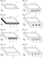
- FIGS. 1A to 1H are schematic perspective views illustrating an example of a method for producing a power storage device in the present disclosure.
- a stacked member 10 is prepared (preparing step).
- the stacked member 10 is obtained, for example, by the following method.
- an electrode E is prepared.
- the electrode E includes a current collector 1, a cathode layer 2 placed on one surface of the current collector 1, and an anode layer (not shown in the figure) placed on the other surface of the current collector 1.
- the electrode E includes a frame member 5 for forming a sealing member, along the outer periphery of the current collector 1.
- FIG. 1A a stacked member 10 is prepared (preparing step).
- the stacked member 10 is obtained, for example, by the following method.
- an electrode E is prepared.
- the electrode E includes a current collector 1, a cathode layer 2 placed on one surface of the current collector 1, and an anode layer (not shown in the figure) placed on the other surface of the current collector 1.
- the electrode E
- a plurality of electrodes E are stacked in the z-axis direction to form an electrode stacked body ⁇ . Also, when stacking the plurality of electrodes E in the z-axis direction, a nest A (nest ⁇ a ) is inserted between plurality of adjacent electrodes E. Then, as shown in FIG. 1C , by heating the side surface of SS 5 of the frame member 5 stacked in the z-axis direction, the frame member 5 stacked in the z-axis direction is heat sealed. Thereby, as shown in FIG.
- a concave portion is a space to which a nest is inserted, and the concave portion may be a groove with a bottom, and may be a hole portion without a bottom.
- a resin portion is molded by feeding a first resin between the nest A and the first concave portion.
- the details of the first placing step and the first molding step are explained referring to FIGS. 2A to 2D .
- the nest A (nest ⁇ a ) sticking out from the sealing member ⁇ is inserted into the first concave portion 21 of the first mold 20.
- the nest B (nest ⁇ b ) is obtained by inflating the nest A (nest ⁇ a ) with resin portion ⁇ a .
- the resin portion ⁇ a may absorb the influence of the misalignment of the nest A (nest ⁇ a ).
- the details of the second placing step and the second molding step are explained referring to FIGS. 3A to 3C .
- the nest B (nest ⁇ b ) sticking out from the sealing member ⁇ is inserted into the second concave portion 31 of the second mold 30.
- the first concave portion (for example, the first concave portion 21 in FIG. 2B ) and the second concave portion 31 have the identical length in the y-axis direction. Further, as shown in FIG.
- the nest B by producing the nest B from the nest A using the first mold, and further molding the resin member using the second mold including the second concave portion whose length in the y-axis direction is identical to that of the first concave portion, a molding failure is suppressed from occurring, when molding a resin member.
- FIGS. 4A to 4C are schematic views illustrating an example of a conventional resin molding method.
- the concave portion of the mold 50 is fit around the nest ⁇ sticking out from the sealing member ⁇ .
- the nest ⁇ may be broken. Therefore, it is necessary to set the dimensions of the concave portion of the mold 50 larger to an extent than the dimensions of the nest ⁇ . Meanwhile, when the dimensions of the concave portion of the mold 50 are too large with respect to the dimensions of the nest ⁇ , the resin may leak through the gap during molding, and may cause a burr.
- the width of the nest (length in the y-axis direction) is extremely long compared to the thickness of the nest (length in the z-axis direction). Therefore, the influence of the nest displacement is noticeably large in the width direction (y-axis direction). Therefore, in the width direction, it is necessary to set the dimensions of the concave portion of the mold relatively longer than the dimensions of the nest. As a result, a molding failure such as burr is more likely to occur notably. Specifically, as shown in FIG. 4C , the resin leaks into the gap between the nest ⁇ and the concave portion of the mold 50, and a molding failure such as burr is more likely to occur notably.
- the preparing step in the present disclosure is a step of preparing a stacked member including an electrode stacked body including a plurality of electrodes stacked in a z-axis direction, a sealing member placed along an outer periphery of the electrode stacked body viewed from the z-axis direction, and a nest A wherein, in an x-axis direction perpendicular to the z-axis direction, one end portion is placed inside the electrode stacked body and the other end portion sticks out from the sealing member.
- the electrode stacked body in the present disclosure includes a plurality of electrodes stacked in a z-axis direction.
- the electrode includes a current collector, an electrode layer (a cathode layer or an anode layer) placed on at least one surface of the current collector.
- the electrode E may be a bipolar electrode including a current collector 1, a cathode layer 2 placed on one surface of the current collector 1, and an anode layer 3 placed on the other surface of the current collector 1.
- the electrode stacked body ⁇ includes a plurality of electrodes E stacked in the z-axis direction (thick direction).
- the electrode E the electrode stacked body ⁇ shown in FIG. 6 includes a bipolar electrode BP 1 , a bipolar electrode BP 2 , a cathode side end portion electrode CA, and an anode side end portion electrode AN.
- the bipolar electrode BP 1 , and the bipolar electrode BP 2 respectively includes a current collector 1, a cathode layer 2 placed on one surface of the current collector 1, and an anode layer 3 placed on the other surface of the current collector 1.
- the cathode side end portion electrode CA includes a current collector 1, and a cathode layer 2 placed on one surface of the current collector 1.
- the anode side end portion electrode AN includes a current collector 1, and an anode layer 3 placed on one surface of the current collector 1.
- the electrode stacked body in the present disclosure is not particularly limited as long as it includes a plurality of electrodes E stacked in the z-axis direction, and it may not include a bipolar electrode.
- the electrode stacked body ⁇ is provided with power generating units U (U 1 to U 3 ).
- the power generating unit U includes a cathode layer 2, an anode layer 3, and a separator 4 placed between the cathode layer 2 and the anode layer 3.
- liquid electrolyte is supplied to the cathode layer 2, anode layer 3 and separator 4, via the through hole H.
- the cathode layer 2, anode layer 3 and separator 4 are immersed in the liquid electrolyte, respectively.
- the electrode stacked body in the present disclosure may include one power generating unit, and may include two or more thereof.
- the electrode stacked body ⁇ shown in FIG. 6 includes a plurality of power generating units (U 1 , U 2 , and U 3 ) stacked in the z-axis direction. As shown in FIG. 6 , a plurality of power generating units may be directly connected to each other. Also, although not particularly shown in the figures, a plurality of power generating units may be connected in parallel to each other. The plurality of power generating units are independent of each other so that the liquid electrolyte does not circulate between thereof. In FIG. 6 , the plurality of power generating units U 1 to U 3 are independent of each other so that the liquid electrolyte does not circulate between thereof. For example, the power generating unit U 1 and the power generating unit U 2 are comparted by the current collector 1 and the sealing member ⁇ , and are independent of each other.
- One power generating unit may be constituted with two bipolar electrodes.
- the electrode stacked body ⁇ includes the bipolar electrode BP 1 , and the bipolar electrode BP 2 , in the z-axis direction.
- a separator 4 is placed between the adjacent bipolar electrode BP 1 and bipolar electrode BP 2 .
- the power generating unit U 2 includes the cathode layer 2 in the bipolar electrode BP 2 , the anode layer 3 in the bipolar electrode BP 1 , and the separator 4 placed between them.
- the power generating unit U 1 includes the cathode layer 2 in the bipolar electrode BP 1 , the anode layer 3 in the anode side end portion electrode AN, and the separator 4 placed between them.
- the power generating unit U 3 includes the anode layer 3 in the bipolar electrode BP 2 , the cathode layer 2 in the cathode side end portion electrode CA, and the separator 4 placed between them.
- the shape of the electrode stacked body in the present disclosure in a plan view (the shape viewed from the z-axis direction) is not particularly limited, and examples thereof may include a quadrilateral shape such as a square shape and a rectangular shape.
- the length of one side of the shape of the electrode stacked body in a plan vie is, for example, 30 cm or more, may be 50 cm or more, and may be 100 cm or more. Meanwhile, the length of one side is, for example, 200 cm or less.
- the sealing member in the present disclosure is placed along an outer periphery of the electrode stacked body viewed from the z-axis direction.
- the sealing member is usually placed on the side surface of the electrode stacked body.
- the side surface of the electrode stacked body is a surface extending in the z-axis direction in the electrode stacked body.
- the side surface of the electrode stacked body is usually a surface facing the z-axis direction, and connecting the top surface (one main face) of the electrode stacked body and the bottom surface (the other main surface) of the electrode stacked body.
- the sealing member is preferably placed in a frame shape, along the outer periphery of the current collector in the electrode stacked body.
- a frame-shaped sealing member ⁇ is placed along the entire outer periphery of the current collector 1.
- the sealing member is preferably a resin member.
- the resin constituting the sealing member (referred to as third resin) may include a thermoplastic resin.
- the thermoplastic resin may include olefin based resins such as polyethylene and polypropylene; and polyester based resins such as polyethylene terephthalate.
- the third resin is preferably the olefin based resins.
- one end portion is placed inside the electrode stacked body and the other end portion sticks out from the sealing member.
- one end portion t1 of the nest A is placed inside the electrode stacked body ⁇
- the other end portion t2 of the nest A sticks out from the sealing member ⁇ .
- the inside of the electrode stacked body ⁇ refers to the central side region of the electrode stacked body ⁇ with reference to the side surface (inner side surface SS 1 ) on the electrode stacked body ⁇ side, among the side surface of the sealing member ⁇ .
- the outside of the sealing member ⁇ refers to a region opposite side to the center of the electrode stacked body ⁇ with reference to the side surface (outer side surface SS 1 ) on the opposite side to the electrode stacked body ⁇ , among the side surface of the sealing member ⁇ .
- the extending direction of the nest A (the direction connecting one end portion t1 and the other end portion t2) is preferably parallel to the x-axis direction. Parallel means that the angle between two directions is 30° or less.
- the nest A is a part of a metallic mold, which is attached to the mother mold such as the first mold, and is a member for producing a resin molded product.
- a part of the nest A (nest ⁇ a ) is fixed by the seal member ⁇ , and a part of the nest A (nest ⁇ a ) is exposed from the sealing member ⁇ .
- the sealing member ⁇ is confined by a confining portion not shown in the figure in the z-axis direction, so that the nest A (nest ⁇ a ) is fixed and held by the sealing member ⁇ located on upper and lower side in the z-axis direction.
- the nest A is, for example, made of metal.
- the thickness of the nest A (length in the z-axis direction) is not particularly limited, and for example, it is 0.1 mm or more and 0.4 mm or less.
- the shape of the nest A in a plan view is not particularly limited, and examples thereof may include a quadrilateral shape such as a square shape and a rectangular shape.
- FIG. 7 is a schematic cross-sectional view (disassembled view) illustrating an example of a method for forming a stacked member in the present disclosure.
- the bipolar electrode BP 1 and the bipolar electrode BP 2 are prepared.
- the bipolar electrode BP 1 includes a cathode layer 2 placed on one surface of the current collector 1, and an anode layer 3 placed on the other surface of the current collector 1.
- the bipolar electrode BP 1 includes a frame member 5a for forming a sealing member, placed along the outer periphery of the current collector 1.
- the frame member 5a is usually placed along the entire outer periphery of the current collector 1.
- the frame member 5a preferably covers a part of one main surface p of the current collector 1, a part of the other main surface q of the current collector 1, and the entire side surface r constituting the outer periphery of the current collector 1.
- the bipolar electrode BP 2 includes a cathode layer 2 placed on one surface of the current collector 1, and an anode layer 3 placed on the other surface of the current collector 1. Further, the bipolar electrode BP 2 includes a frame member 5b for forming a sealing member, placed along the outer periphery of the current collector 1. The details of the bipolar electrode BP 2 are similar to those of the bipolar electrode BP 1 described above.
- the anode 3 in the bipolar electrode BP 1 and the cathode layer 2 in the bipolar electrode BP 2 are faced to each other via the separator 4. In doing so, at least a part of the outer periphery of the separator 4 is placed between the frame member 5a and frame member 5b. Also, as shown in FIG. 7 , the nest A (nest ⁇ a ) and frame member (spacer) 5c are placed between the frame member 5a in the bipolar electrode BP 1 and the frame member 5b in the bipolar electrode BP 2 . Then, although not shown in the figures, similar to FIG. 6 , a cathode side end portion electrode CA and an anode side end portion electrode AN are also stacked. After that, a plurality of stacked frame members are welded together to form a sealing member. In this way, a stacked member is obtained.
- the first placing step of in the present disclosure is a step of inserting the nest A sticking out from the sealing member in the stacked member, into a first concave portion in a first mold.
- the first mold 20 is placed around the nest A (nest ⁇ a ), establishing a space for molding a resin portion (not shown in the figure).
- the first concave portion 21 in the first mold 20 is preferably a groove portion with a bottom 21a. This is because it is easy to form a resin portion with the desired shape.
- the first mold 20 is placed by adjusting the position of the first concave portion 21 in the y-axis direction.
- the method for adjusting the position of the first concave portion 21 is not particularly limited, and examples thereof may include a method wherein the position of the first concave portion 21 is adjusted by aligning the end surface of the first mold 20 with the reference surface C (surface extending in the x-axis direction), as shown in FIG. 2B .
- the reference surface C surface extending in the x-axis direction
- the displacement in the y-axis direction may be prevented effectively.
- the first molding step in the present disclosure is a step of molding a resin portion by feeding a first resin between the nest A and the first concave portion, and obtaining a nest B including the nest A and the resin portion, after the first placing step.
- the method for forming a resin portion is not particularly limited, and examples thereof may include resin molding methods such as injection molding method.
- the first resin constituting the resin portion may include a thermoplastic resin.
- the thermoplastic resin may include olefin based resins such as polyethylene and polypropylene; and polyester based resins such as polyethylene terephthalate.
- the first resin is preferably the polyester based resins.
- the melting point T M1 of the first resin constituting the resin portion is preferably higher than the melting point T M2 of the second resin constituting the resin member described later. This is because the first resin may be prevented from melting during the molding of the resin member.
- the difference between T M1 and T M2 is, for example, 20°C or more, may be 50°C or more, and may be 100°C or more.
- the compatibility between the first resin constituting the resin portion and the second resin constituting the resin member described later is preferably low. This is because, when the compatibility between the first resin and the second resin is low, it is easier to pull out the nest B.
- the first resin is preferably the polyester based resins
- the second resin is preferably the olefin based resins.
- the compatibility between the first resin constituting the resin portion and the third resin constituting the sealing member described above is preferably low. This is because, when the compatibility between the first resin and the third resin is low, it is easier to pull out the nest B.
- the first resin is preferably the polyester based resins
- the third resin is preferably the olefin based resins.
- FIGS. 8A to 8D are schematic views illustrating an example of a nest B in the present disclosure. Specifically, they are schematic views wherein the center of nest B in the z-axis direction is cut in the x-y surface.
- the nest B when viewed from the z-axis direction, the nest B (nest ⁇ b ) preferably includes the resin portion ⁇ 1 on both sides of the nest A (nest ⁇ a ) in the y-axis direction. In other words, in the y-axis direction, it is preferable that the resin portions ⁇ 1 are placed so as to sandwich the nest A (nest ⁇ a ).
- the width (length in the y-axis direction) of nest A (nest ⁇ a ) is regarded as W 1 and the width of nest B (nest y b ) is regarded as W 2 .
- the ratio of W 2 with respect to W 1 (W 2 /W 1 ) is, for example, 1.1 or more, and may be 1.5 or more.
- W 2/ W 1 is, for example, 3.0 or less.
- the resin portion ⁇ 1 may be placed so as to cover the other end portion t2 of the nest A (nest ⁇ a ). Meanwhile, as shown in FIGS 8B to 8D , the other end portion t2 of the nest A (nest ⁇ a ) may be exposed from the resin portion ⁇ 1 . Also, as shown in FIG. 8B , in the x-axis direction, the position of the other end portion t2 may accord with the position of the end portion of the resin portion ⁇ 1 . Also, as shown in FIG. 8C , in the x-axis direction, the position of the end portion of the resin portion ⁇ 1 may protrude from the position of the other end portion t2. Also, as shown in FIG. 8D , in the x-axis direction, the position of the other end portion t2 may protrude from the position of the end portion of the resin portion ⁇ 1 .
- FIGS. 9A to 9C are schematic views illustrating an example of a nest B in the present disclosure. Specifically, they are schematic views wherein the center of nest B in the y-axis direction is cut in the x-z surface.
- the nest B when viewed from the y-axis direction, the nest B (nest ⁇ b ) may include the resin portion ⁇ 1 on both sides of the nest A (nest ⁇ a ) in the z-axis direction.
- the resin portion ⁇ 1 may be placed on both surfaces (both surfaces whose normal line direction is the z-axis direction) of the nest A (nest ⁇ a ).
- FIG. 9A when viewed from the y-axis direction, the nest B (nest ⁇ b ) may include the resin portion ⁇ 1 on both sides of the nest A (nest ⁇ a ) in the z-axis direction.
- the resin portion ⁇ 1 may be placed on both surfaces (both surfaces whose normal line direction is the z-axi
- the nest B when viewed from the y-axis direction, the nest B (nest ⁇ b ) may include the resin portion ⁇ 1 on one side of the nest A (nest ⁇ a ) in the z-axis direction.
- the resin portion ⁇ 1 may be placed only on one surface (one surface whose normal line direction is the z-axis direction) of the nest A (nest ⁇ a ).
- the resin portion ⁇ 1 may not be placed on the surface whose normal line direction is the z-axis direction.
- the thickness (length in the z-axis direction) of nest A is regarded as T 1 and the thickness of nest B (nest ⁇ b ) is regarded as T 2 .
- the ratio of T 2 with respect to T 1 is, for example, 1.0 or more, and may be 1.5 or more. Meanwhile, the T 2 /T 1 is, for example, 3.0 or less.
- the shape of the nest B in a plan view is not particularly limited, and examples thereof may include a quadrilateral shape such as a square shape and a rectangular shape.
- the second placing step of in the present disclosure is a step of inserting the nest B sticking out from the sealing member in the stacked member, into a second concave portion in a second mold. Also, in the present disclosure, length of the first concave portion in a y-axis direction is identical to that of the second concave portion.
- the length of the first concave portion in a y-axis direction is identical to that of the second concave portion means that they are identical to the extent that resin leakage does not occur during molding.
- the difference in length between the two is, for example, 1 mm or less, may be 0.5 mm or less, and may be 0.1 mm or less.
- the length of the second concave portion in the y-axis direction is slightly longer than the length of the first concave portion in the y-axis direction. The reason therefore is to prevent the interference between nest B and the second concave portion.
- the difference between the two may be, for example 0.005 mm or more, and may be 0.01 mm or more.
- the nest B (nest ⁇ b ) sticking out from the sealing member ⁇ in the stacked member 10 is inserted into a second concave portion 31 in the second mold 30.
- the second mold 30 is placed so as to establish a space, for molding a resin member 40, between the nest B (nest ⁇ b ) and the second mold 30.
- the nest B (nest ⁇ b) is fixed and held by the second concave portion 31.
- the second concave portion 31 in the second mold 30 is a hole portion without a bottom.
- the second concave portion 31 may be a groove portion with a bottom.
- the second mold 30 is placed by adjusting the position of the second concave portion 31 in the y-axis direction.
- the method for adjusting the position of the second concave portion 31 is not particularly limited, and examples thereof may include a method wherein the position of the second concave portion 31 is adjusted by aligning the end surface of the second mold 30 with the reference surface C (surface extending in the x-axis direction), as shown in FIG. 3B .
- the adjustment of the position of the second concave portion 31 in the second placing step and the adjustment of the position of the first concave portion 21 in the first placing step are preferably based on the same criteria.
- the second molding step in the present disclosure is a step of molding a resin member by feeding a second resin between the stacked member and the second mold, after the second placing step.
- the resin member is a member configured to seal the electrode stacked body, similar to the sealing member described above.
- the method for molding a resin member is not particularly limited, and examples thereof may include resin molding methods such as injection molding.
- the second resin constituting the resin member may include thermoplastic resins.
- the thermoplastic resin may include olefin based resins such as polyethylene and polypropylene; and polyester based resins such as polyethylene terephthalate. Among them, the second resin is preferably the olefin based resins.
- the compatibility between the second resin constituting the resin member and the third resin constituting the sealing member described above is preferably high. This is because, when the compatibility between the second resin and the third resin is high, the adhesiveness between the resin member and sealing member is increased.
- the second resin and the third resin are preferably the olefin based resins.
- the resin member is placed along the outer periphery of the stacked member.
- the resin member may be placed along at least a part of the outer periphery of the stacked member, and may be placed along the entire outer periphery of the stacked member.
- the resin member may have a partition wall structure that comparts each nest B, on the side surface (the side surface opposite side to the sealing member side surface).
- the method for producing a power storage device in the present disclosure may include a through hole forming step of forming a first through hole passing through the sealing member and a second through hole passing through the resin member, by pulling the nest B out from the stacked member and the resin member. Specifically, as shown in FIG. 1H , after the second molding step, the nest B (nest ⁇ b ) is pulled out from the stacked member 10 and resin member 40. Thereby, as shown in FIGS. 10A to 10B and FIGS. 11A to 11B , a through hole H including a first through hole H 1 passing through the sealing member ⁇ , and a second through hole H 2 communicated with the first through hole H 1 and passing through the resin member 40, is formed.
- the width W 1 of the nest A (nest ⁇ a ) and the width W 3 of the first through hole H 1 are preferably the same.
- the width of the nest B (nest ⁇ b ) and the width W 4 of the second through hole H 2 are preferably the same.
- the preferable range for the ratio of W 4 with respect to W 3 (W 4 /W 3 ) is similar to W 2 /W 1 described above.
- the thickness T 1 of the nest A (nest ⁇ a ) and the length T 3 of the first through hole H 1 in the z-axis direction are preferably the same.
- the thickness T 2 of the nest B (nest ⁇ b ) and the length T 4 of the second through hole H 2 in the z-axis direction are preferably the same.
- the preferable range for the ratio of T 4 with respect to T 3 (T 4 /T 3 ) is similar to T 2 /T 1 described above.
- the first resin constituting the resin portion of the nest B remains, as a residual component, on the inner wall portion in the second through hole, due to friction. That is, after pulling the nest B out, there may be residual component of the first resin on the inner wall portion in the second through hole.
- the melting point of the first resin is preferably higher than the second resin constituting the resin member.
- the residual component of the first resin may be present on the inner wall portion in the second through hole, and the residual component may not be present on the inner wall portion in the first through hole.
- the method for producing a power storage device in the present disclosure may include a liquid electrolyte supplying step of supplying liquid electrolyte into the electrode stacked body, via the through hole.
- a method for supplying liquid electrolyte is not particularly limited, and known methods may be used.
- the method for producing a power storage device in the present disclosure may include a sealing step of sealing the through hole.
- a method for sealing the through hole is not particularly limited, and examples thereof may include a method wherein a film is used for the sealing. Also, power storage device obtained by each step described above is explained in "B. Power storage device" later.
- FIG. 12 is a schematic cross-sectional view illustrating an example of a power storage device in the present disclosure.
- a power storage device 100 shown in FIG. 12 comprises: an electrode stacked body ⁇ including a plurality of electrodes stacked in a z-axis direction; a sealing member ⁇ placed along an outer periphery of the electrode stacked body ⁇ viewed from the z-axis direction; and a resin member 40 placed along an outer periphery of the sealing member viewed from the z-axis direction.
- the power storage device 100 comprises a first through hole H 1 passing through the sealing member ⁇ , and a second through hole H 2 communicated with the first through hole H 1 and passing through the resin member 40.
- the width W 4 of the second through hole H 2 (the length in the y-axis direction) is longer than the width W 3 of the first though hole H 1 (the length in the y-axis direction).
- the power storage device in the present disclosure preferably includes liquid electrolyte in the electrode stacked body. Also, as shown in FIG. 12 , the second through hole H 2 may be sealed by a film 60 placed on the side surface of the resin member 40 (the side surface opposite to the sealing member ⁇ side surface).
- the power storage device in the present disclosure may include a secondary battery (such as a lithium ion secondary battery) and an electric double layer capacitor.
- examples of the use application of the power storage device may include a power supply of a vehicle such as a hybrid electric vehicle (HEV), a plug-in hybrid electric vehicle (PHEV), a battery electric vehicle (BEV), a gasoline-powered vehicle, and a diesel-powered vehicle.
- a vehicle such as a hybrid electric vehicle (HEV), a plug-in hybrid electric vehicle (PHEV), a battery electric vehicle (BEV).
- HEV hybrid electric vehicle
- PHEV plug-in hybrid electric vehicle
- BEV battery electric vehicle
- the power storage device in the present disclosure may be used as a power source for moving objects other than vehicles (such as railroad vehicles, ships, and airplanes), and may be used as a power source for electric appliances such as information processing apparatuses.
- the present disclosure is not limited to the embodiments.
- the embodiments are exemplification, and any other variations are intended to be included in the technical scope of the present disclosure if they have substantially the same constitution as the technical idea described in the claim of the present disclosure and offer similar operation and effect thereto.
Landscapes
- Chemical & Material Sciences (AREA)
- Chemical Kinetics & Catalysis (AREA)
- General Chemical & Material Sciences (AREA)
- Electrochemistry (AREA)
- Engineering & Computer Science (AREA)
- Manufacturing & Machinery (AREA)
- Mechanical Engineering (AREA)
- Power Engineering (AREA)
- Microelectronics & Electronic Packaging (AREA)
- Materials Engineering (AREA)
- Sealing Battery Cases Or Jackets (AREA)
- Secondary Cells (AREA)
- Electric Double-Layer Capacitors Or The Like (AREA)
Abstract
Description
- The present disclosure relates to a method for producing a power storage device and a power storage device.
- In a method for producing a power storage device such as a secondary battery, the technology wherein a sealing member is formed along the outer periphery of the electrode stacked body, and further, a resin member is formed along the outer periphery of the sealing member, has been known. Also, a technology wherein a through hole passing through a sealing member and a resin member is formed using a nest (insert), has been known.
- For example,
Patent Literature 1 discloses a power storage device comprising a stacked body including a bipolar electrode; a first sealing portion placed along the outer periphery of the stacked body; a second sealing portion placed along the outer periphery of the first sealing portion; and a through hole passing through the first sealing portion and second sealing portion. Also,Patent Literature 1 discloses the formation of the second sealing portion by preparing a stacked member (a member including the stacked body and first sealing portion) incorporated with a nest, and then, injection molding. - Patent Literature 1: Japanese Patent Application Laid-Open (
JP-A) No. 2019-16459 - When a resin member is molded on the stacked member incorporated with a nest by a resin molding method, the nest is inserted into a concave portion of the mold, and held and fixed therein. When the nest is inserted into the concave portion of the mold, if the nest and the concave portion of the mold interfere with each other, the nest may be broken. Therefore, it is necessary to set the dimensions of the concave portion of the mold larger to an extent than the dimensions of the nest. Meanwhile, when the dimensions of the concave portion of the mold are too large with respect to the dimensions of the nest, the resin may leak through the gap during molding, and may cause a burr.
- Also, the influence of the nest displacement is noticeably large in the width direction (y-axis direction). Therefore, in the width direction, it is necessary to set the dimensions of the concave portion of the mold relatively larger than the dimensions of the nest. As a result, a molding failure such as burr is more likely to occur notably.
- The present disclosure has been made in view of the above circumstances, and a main object of the present disclosure is to provide a method for producing a power storage device wherein a molding failure hardly occurs when molding a resin member.
-
- [1] A method for producing a power storage device, the method comprising:
- a preparing step of preparing a stacked member including an electrode stacked body including a plurality of electrodes stacked in a z-axis direction, a sealing member placed along an outer periphery of the electrode stacked body viewed from the z-axis direction, and a nest A wherein, in an x-axis direction perpendicular to the z-axis direction, one end portion is placed inside the electrode stacked body and the other end portion sticks out from the sealing member;
- a first placing step of inserting the nest A sticking out from the sealing member in the stacked member, into a first concave portion in a first mold;
- after the first placing step, a first molding step of molding a resin portion by feeding a first resin between the nest A and the first concave portion, and obtaining a nest B including the nest A and the resin portion;
- after the first molding step, a second placing step of inserting the nest B sticking out from the sealing member in the stacked member, into a second concave portion in a second mold; and
- after the second placing step, a second molding step of molding a resin member by feeding a second resin between the stacked member and the second mold; and
- a length of the first concave portion in a y-axis direction perpendicular to the z-axis direction and the x-axis direction is identical to that of the second concave portion.
- [2] The method for producing a power storage device according to [1], wherein, viewed from the z-axis direction, the nest B includes the resin portion on both sides of the nest A in the y-axis direction.
- [3] The method for producing a power storage device according to [1] or [2], wherein, viewed from the y-axis direction, the nest B includes the resin portion on both sides of the nest A in the z-axis direction.
- [4] The method for producing a power storage device according to any one of [1] to [3], wherein a melting point of the first resin is higher than the melting point of the second resin.
- [5] The method for producing a power storage device according to any one of [1] to [4], wherein the sealing member is a resin member including a third resin;
- the third resin and the second resin are olefin based resin; and
- the first resin is polyester based resin.
- [6] The method for producing a power storage device according to any one of [1] to [5], wherein, after the second molding step, the method for producing comprises a through hole forming step of forming a first through hole passing through the sealing member and a second through hole passing through the resin member, by pulling the nest B out from the stacked member and the resin member.
- [7] A power storage device comprising: an electrode stacked body including a plurality of electrodes stacked in a z-axis direction; a sealing member placed along an outer periphery of the electrode stacked body viewed from the z-axis direction; and a resin member placed along an outer periphery of the sealing member viewed from the z-axis direction; and
- in an x-axis direction perpendicular to the z-axis direction, the power storage device comprises a first through hole passing through the sealing member, and a second through hole communicated with the first through hole and passing through the resin member; and
- when a direction perpendicular to the x-axis direction and the z-axis direction is regarded as a y-axis direction, a length of the second through hole in the y-axis direction is longer than a length of the first though hole in the y-axis direction.
- [8] The power storage device according to [7], wherein a length of the second through hole in the z-axis direction is longer than a length of the first though hole in the z-axis direction.
- [9] The power storage device according to [7] or [8], wherein a residual component of a first resin, having a melting point higher than a second resin included in the resin member, exists in an inner wall portion in the second through hole.
- The method for producing a power storage device in the present disclosure exhibits effects that a molding failure hardly occurs when molding a resin member.
-
-
FIGS. 1A to 1H are schematic perspective views illustrating an example of a method for producing a power storage device in the present disclosure. -
FIGS. 2A to 2D are schematic views illustrating an example of the first placing step and the first molding step in the present disclosure. -
FIGS. 3A to 3C are schematic views illustrating an example of the second placing step and the second molding step in the present disclosure. -
FIGS. 4A to 4C are schematic views illustrating an example of a conventional resin molding method. -
FIG. 5 is a schematic cross-sectional view illustrating an example of an electrode in the present disclosure. -
FIG. 6 is a schematic cross-sectional view illustrating an example of a stacked member in the present disclosure. -
FIG. 7 is a schematic cross-sectional view illustrating an example of a method for forming a stacked member in the present disclosure. -
FIGS. 8A to 8D are schematic views illustrating an example of a nest B in the present disclosure. -
FIGS. 9A to 9C are schematic views illustrating an example of a nest B in the present disclosure. -
FIGS. 10A to 10B are schematic views illustrating an example of a nest B and a through hole in the present disclosure. -
FIGS. 11A to 11B are schematic views illustrating an example of a nest B and a through hole in the present disclosure. -
FIG. 12 is a schematic cross-sectional view illustrating an example of a power storage device in the present disclosure. - The embodiments in the present disclosure will be hereinafter explained in details with reference to drawings. Each drawing described as below is a schematic view, and the size and the shape of each portion are appropriately exaggerated in order to be understood easily. Furthermore, in the present description, upon expressing an embodiment of arranging one member with respect to the other member, when it is expressed simply "on" or "below", both of when the other member is directly arranged on or below the one member so as to contact with each other, and when the other member is arranged above or below the one member interposing an additional member, can be included unless otherwise described.
-
FIGS. 1A to 1H are schematic perspective views illustrating an example of a method for producing a power storage device in the present disclosure. Firstly, as shown inFIGS. 1A to 1C , astacked member 10 is prepared (preparing step). The stackedmember 10 is obtained, for example, by the following method. As shown inFIG. 1A , an electrode E is prepared. The electrode E includes acurrent collector 1, acathode layer 2 placed on one surface of thecurrent collector 1, and an anode layer (not shown in the figure) placed on the other surface of thecurrent collector 1. Also, the electrode E includes aframe member 5 for forming a sealing member, along the outer periphery of thecurrent collector 1. Then, as shown inFIG. 1B , a plurality of electrodes E are stacked in the z-axis direction to form an electrode stacked body α. Also, when stacking the plurality of electrodes E in the z-axis direction, a nest A (nest γa) is inserted between plurality of adjacent electrodes E. Then, as shown inFIG. 1C , by heating the side surface of SS5 of theframe member 5 stacked in the z-axis direction, theframe member 5 stacked in the z-axis direction is heat sealed. Thereby, as shown inFIG. 1C , astacked member 10 including an electrode stacked body α, a sealing member β placed along the outer periphery of the electrode stacked body α viewed from the z-axis direction, and a nest A (nest γa), is obtained. - Then, as shown in
FIG. 1D , the nest A (not shown in the figure) sticking out from the sealing member β in the stackedmember 10, is inserted into a first concave portion (not shown in the figure) in a first mold 20 (first placing step). In the present disclosure, a concave portion is a space to which a nest is inserted, and the concave portion may be a groove with a bottom, and may be a hole portion without a bottom. Then, a resin portion is molded by feeding a first resin between the nest A and the first concave portion. Thereby, as shown inFIG. 1E , a nest B (nest γb) including the nest A (nest γa) and the resin portion γ1, is obtained (first molding step). - Here, the details of the first placing step and the first molding step are explained referring to
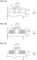
FIGS. 2A to 2D . In the first placing step, as shown inFIGS. 2A and 2B , the nest A (nest γa) sticking out from the sealing member β is inserted into the firstconcave portion 21 of thefirst mold 20. For example, aligning the end surface offirst mold 20 with reference surface C, the position of firstconcave portion 21 with respect to the nest A (nest γa) is adjusted. Then, as shown inFIGS. 2C and 2D , the nest B (nest γb) is obtained by inflating the nest A (nest γa) with resin portion γa. In the nest B (nest γb), the resin portion γa may absorb the influence of the misalignment of the nest A (nest γa). - Then, as shown in
FIG. 1F , the nest B (nest γb) sticking out from the sealing member β in the stackedmember 10, is inserted into a secondconcave portion 31 in the second mold 30 (second placing step). Then, a second resin is fed between thestacked member 10 and thesecond mold 30. Thereby, as shown inFIG. 1G ,resin member 40 is molded on the stackedmember 10 side surface (second molding step). - Here, the details of the second placing step and the second molding step are explained referring to
FIGS. 3A to 3C . As shown inFIGS. 3A and 3B , the nest B (nest γb) sticking out from the sealing member β is inserted into the secondconcave portion 31 of thesecond mold 30. In the present disclosure, the first concave portion (for example, the firstconcave portion 21 inFIG. 2B ) and the secondconcave portion 31 have the identical length in the y-axis direction. Further, as shown inFIG. 3B for example, aligning the end surface of thesecond mold 30 with reference surface C, the position of secondconcave portion 31 with respect to the nest B (nest γb) is adjusted, similarly to the position of firstconcave portion 21 with respect to the nest A (nest γa). Thereby, as shown inFIG. 3B , a high-precision positioning of the nest B (nest γb) and the secondconcave portion 31 of thesecond mold 30 is possible. As a result, the resin may be prevented from being leaked into the gap between the nest B (nest γb) and thesecond mold 30, so that a desiredresin member 40 is molded, as shown inFIG. 3C . - According to the present disclosure, by producing the nest B from the nest A using the first mold, and further molding the resin member using the second mold including the second concave portion whose length in the y-axis direction is identical to that of the first concave portion, a molding failure is suppressed from occurring, when molding a resin member.
-
FIGS. 4A to 4C are schematic views illustrating an example of a conventional resin molding method. As shown inFIGS. 4A and 4B , the concave portion of themold 50 is fit around the nest γ sticking out from the sealing member β. As described above, when the nest γ is inserted into the concave portion of themold 50, if the nest γ and the concave portion of themold 50 interfere with each other, the nest γ may be broken. Therefore, it is necessary to set the dimensions of the concave portion of themold 50 larger to an extent than the dimensions of the nest γ. Meanwhile, when the dimensions of the concave portion of themold 50 are too large with respect to the dimensions of the nest γ, the resin may leak through the gap during molding, and may cause a burr. - In general, the width of the nest (length in the y-axis direction) is extremely long compared to the thickness of the nest (length in the z-axis direction). Therefore, the influence of the nest displacement is noticeably large in the width direction (y-axis direction). Therefore, in the width direction, it is necessary to set the dimensions of the concave portion of the mold relatively longer than the dimensions of the nest. As a result, a molding failure such as burr is more likely to occur notably. Specifically, as shown in
FIG. 4C , the resin leaks into the gap between the nest γ and the concave portion of themold 50, and a molding failure such as burr is more likely to occur notably. - In contrast, in the present disclosure, as shown in
FIGS. 2A to 2D andFIGS. 3A to 3C described above, by producing the nest B from the nest A using the first mold, and further molding the resin member using the second mold including the second concave portion whose length in the y-axis direction is identical to that of the first concave portion, a molding failure may be suppressed from occurring, when molding a resin member. - The preparing step in the present disclosure is a step of preparing a stacked member including an electrode stacked body including a plurality of electrodes stacked in a z-axis direction, a sealing member placed along an outer periphery of the electrode stacked body viewed from the z-axis direction, and a nest A wherein, in an x-axis direction perpendicular to the z-axis direction, one end portion is placed inside the electrode stacked body and the other end portion sticks out from the sealing member.
- The electrode stacked body in the present disclosure includes a plurality of electrodes stacked in a z-axis direction. The electrode includes a current collector, an electrode layer (a cathode layer or an anode layer) placed on at least one surface of the current collector. As shown in
FIG. 5 , the electrode E may be a bipolar electrode including acurrent collector 1, acathode layer 2 placed on one surface of thecurrent collector 1, and ananode layer 3 placed on the other surface of thecurrent collector 1. - As shown in
FIG. 6 , the electrode stacked body α includes a plurality of electrodes E stacked in the z-axis direction (thick direction). As the electrode E, the electrode stacked body α shown inFIG. 6 includes a bipolar electrode BP1, a bipolar electrode BP2, a cathode side end portion electrode CA, and an anode side end portion electrode AN. The bipolar electrode BP1, and the bipolar electrode BP2 respectively includes acurrent collector 1, acathode layer 2 placed on one surface of thecurrent collector 1, and ananode layer 3 placed on the other surface of thecurrent collector 1. The cathode side end portion electrode CA includes acurrent collector 1, and acathode layer 2 placed on one surface of thecurrent collector 1. The anode side end portion electrode AN includes acurrent collector 1, and ananode layer 3 placed on one surface of thecurrent collector 1. Also, the electrode stacked body in the present disclosure is not particularly limited as long as it includes a plurality of electrodes E stacked in the z-axis direction, and it may not include a bipolar electrode. - As shown in
FIG. 6 , the electrode stacked body α is provided with power generating units U (U1 to U3). The power generating unit U includes acathode layer 2, ananode layer 3, and aseparator 4 placed between thecathode layer 2 and theanode layer 3. After the through hole H illustrated inFIG. 1H described above is formed, liquid electrolyte is supplied to thecathode layer 2,anode layer 3 andseparator 4, via the through hole H. As a result, thecathode layer 2,anode layer 3 andseparator 4 are immersed in the liquid electrolyte, respectively. Also, the electrode stacked body in the present disclosure may include one power generating unit, and may include two or more thereof. - The electrode stacked body α shown in
FIG. 6 includes a plurality of power generating units (U1, U2, and U3) stacked in the z-axis direction. As shown inFIG. 6 , a plurality of power generating units may be directly connected to each other. Also, although not particularly shown in the figures, a plurality of power generating units may be connected in parallel to each other. The plurality of power generating units are independent of each other so that the liquid electrolyte does not circulate between thereof. InFIG. 6 , the plurality of power generating units U1 to U3 are independent of each other so that the liquid electrolyte does not circulate between thereof. For example, the power generating unit U1 and the power generating unit U2 are comparted by thecurrent collector 1 and the sealing member β, and are independent of each other. - One power generating unit may be constituted with two bipolar electrodes. In
FIG.6 , the electrode stacked body α includes the bipolar electrode BP1, and the bipolar electrode BP2, in the z-axis direction. Aseparator 4 is placed between the adjacent bipolar electrode BP1 and bipolar electrode BP2. The power generating unit U2 includes thecathode layer 2 in the bipolar electrode BP2, theanode layer 3 in the bipolar electrode BP1, and theseparator 4 placed between them. Meanwhile, the power generating unit U1 includes thecathode layer 2 in the bipolar electrode BP1, theanode layer 3 in the anode side end portion electrode AN, and theseparator 4 placed between them. Also, the power generating unit U3 includes theanode layer 3 in the bipolar electrode BP2, thecathode layer 2 in the cathode side end portion electrode CA, and theseparator 4 placed between them. - The shape of the electrode stacked body in the present disclosure, in a plan view (the shape viewed from the z-axis direction) is not particularly limited, and examples thereof may include a quadrilateral shape such as a square shape and a rectangular shape. The length of one side of the shape of the electrode stacked body in a plan vie is, for example, 30 cm or more, may be 50 cm or more, and may be 100 cm or more. Meanwhile, the length of one side is, for example, 200 cm or less.
- The sealing member in the present disclosure is placed along an outer periphery of the electrode stacked body viewed from the z-axis direction. The sealing member is usually placed on the side surface of the electrode stacked body. The side surface of the electrode stacked body is a surface extending in the z-axis direction in the electrode stacked body. Also, the side surface of the electrode stacked body is usually a surface facing the z-axis direction, and connecting the top surface (one main face) of the electrode stacked body and the bottom surface (the other main surface) of the electrode stacked body.
- Viewed from the z-axis direction, the sealing member is preferably placed in a frame shape, along the outer periphery of the current collector in the electrode stacked body. For example, in
FIG. 1A , a frame-shaped sealing member β is placed along the entire outer periphery of thecurrent collector 1. The sealing member is preferably a resin member. Examples of the resin constituting the sealing member (referred to as third resin) may include a thermoplastic resin. Examples of the thermoplastic resin may include olefin based resins such as polyethylene and polypropylene; and polyester based resins such as polyethylene terephthalate. Among those, the third resin is preferably the olefin based resins. - In the nest A in the present disclosure, in the x-axis direction perpendicular to the z-axis direction, one end portion is placed inside the electrode stacked body and the other end portion sticks out from the sealing member. As shown in
FIG. 6 , in the x-axis direction, one end portion t1 of the nest A (nest γa) is placed inside the electrode stacked body α, and the other end portion t2 of the nest A (nest γa) sticks out from the sealing member β. - Viewed from the z-axis direction, the inside of the electrode stacked body α refers to the central side region of the electrode stacked body α with reference to the side surface (inner side surface SS1) on the electrode stacked body α side, among the side surface of the sealing member β. Viewed from the z-axis direction, the outside of the sealing member β refers to a region opposite side to the center of the electrode stacked body α with reference to the side surface (outer side surface SS1) on the opposite side to the electrode stacked body α, among the side surface of the sealing member β. Also, the extending direction of the nest A (the direction connecting one end portion t1 and the other end portion t2) is preferably parallel to the x-axis direction. Parallel means that the angle between two directions is 30° or less. The nest A is a part of a metallic mold, which is attached to the mother mold such as the first mold, and is a member for producing a resin molded product.
- As shown in
FIG. 6 , a part of the nest A (nest γa) is fixed by the seal member β, and a part of the nest A (nest γa) is exposed from the sealing member β. Also, the sealing member β is confined by a confining portion not shown in the figure in the z-axis direction, so that the nest A (nest γa) is fixed and held by the sealing member β located on upper and lower side in the z-axis direction. The nest A is, for example, made of metal. The thickness of the nest A (length in the z-axis direction) is not particularly limited, and for example, it is 0.1 mm or more and 0.4 mm or less. Also, the shape of the nest A in a plan view (the shape viewed from the z-axis direction) is not particularly limited, and examples thereof may include a quadrilateral shape such as a square shape and a rectangular shape. -
FIG. 7 is a schematic cross-sectional view (disassembled view) illustrating an example of a method for forming a stacked member in the present disclosure. As shown inFIG. 7 , the bipolar electrode BP1 and the bipolar electrode BP2 are prepared. The bipolar electrode BP1 includes acathode layer 2 placed on one surface of thecurrent collector 1, and ananode layer 3 placed on the other surface of thecurrent collector 1. - Further, the bipolar electrode BP1 includes a
frame member 5a for forming a sealing member, placed along the outer periphery of thecurrent collector 1. Viewed from the z-axis direction, theframe member 5a is usually placed along the entire outer periphery of thecurrent collector 1. For example, when the outer periphery shape of thecurrent collector 1 is quadrilateral shape, theframe member 5a is placed along the entire outer periphery of the quadrilateral shape. Also, as shown inFIG. 7 , theframe member 5a preferably covers a part of one main surface p of thecurrent collector 1, a part of the other main surface q of thecurrent collector 1, and the entire side surface r constituting the outer periphery of thecurrent collector 1. - As shown in
FIG. 7 , the bipolar electrode BP2 includes acathode layer 2 placed on one surface of thecurrent collector 1, and ananode layer 3 placed on the other surface of thecurrent collector 1. Further, the bipolar electrode BP2 includes aframe member 5b for forming a sealing member, placed along the outer periphery of thecurrent collector 1. The details of the bipolar electrode BP2 are similar to those of the bipolar electrode BP1 described above. - As shown in
FIG. 7 , theanode 3 in the bipolar electrode BP1 and thecathode layer 2 in the bipolar electrode BP2 are faced to each other via theseparator 4. In doing so, at least a part of the outer periphery of theseparator 4 is placed between theframe member 5a andframe member 5b. Also, as shown inFIG. 7 , the nest A (nest γa) and frame member (spacer) 5c are placed between theframe member 5a in the bipolar electrode BP1 and theframe member 5b in the bipolar electrode BP2. Then, although not shown in the figures, similar toFIG. 6 , a cathode side end portion electrode CA and an anode side end portion electrode AN are also stacked. After that, a plurality of stacked frame members are welded together to form a sealing member. In this way, a stacked member is obtained. - The first placing step of in the present disclosure is a step of inserting the nest A sticking out from the sealing member in the stacked member, into a first concave portion in a first mold.
- As shown in
FIG. 2B , the nest A (nest γa) sticking out from the sealing member β in the stackedmember 10, is inserted into a firstconcave portion 21 in thefirst mold 20. In doing so, thefirst mold 20 is placed around the nest A (nest γa), establishing a space for molding a resin portion (not shown in the figure). The firstconcave portion 21 in thefirst mold 20 is preferably a groove portion with a bottom 21a. This is because it is easy to form a resin portion with the desired shape. Also, as shown inFIG. 2B , thefirst mold 20 is placed by adjusting the position of the firstconcave portion 21 in the y-axis direction. The method for adjusting the position of the firstconcave portion 21 is not particularly limited, and examples thereof may include a method wherein the position of the firstconcave portion 21 is adjusted by aligning the end surface of thefirst mold 20 with the reference surface C (surface extending in the x-axis direction), as shown inFIG. 2B . By using a surface extending in the x-axis direction as the reference surface, the displacement in the y-axis direction may be prevented effectively. - The first molding step in the present disclosure is a step of molding a resin portion by feeding a first resin between the nest A and the first concave portion, and obtaining a nest B including the nest A and the resin portion, after the first placing step.
- The method for forming a resin portion is not particularly limited, and examples thereof may include resin molding methods such as injection molding method. Examples of the first resin constituting the resin portion may include a thermoplastic resin. Examples of the thermoplastic resin may include olefin based resins such as polyethylene and polypropylene; and polyester based resins such as polyethylene terephthalate. Among them, the first resin is preferably the polyester based resins.
- The melting point TM1 of the first resin constituting the resin portion is preferably higher than the melting point TM2 of the second resin constituting the resin member described later. This is because the first resin may be prevented from melting during the molding of the resin member. The difference between TM1 and TM2 is, for example, 20°C or more, may be 50°C or more, and may be 100°C or more.
- The compatibility between the first resin constituting the resin portion and the second resin constituting the resin member described later is preferably low. This is because, when the compatibility between the first resin and the second resin is low, it is easier to pull out the nest B. Specifically, the first resin is preferably the polyester based resins, and the second resin is preferably the olefin based resins.
- The compatibility between the first resin constituting the resin portion and the third resin constituting the sealing member described above is preferably low. This is because, when the compatibility between the first resin and the third resin is low, it is easier to pull out the nest B. Specifically, the first resin is preferably the polyester based resins, and the third resin is preferably the olefin based resins.
-
FIGS. 8A to 8D are schematic views illustrating an example of a nest B in the present disclosure. Specifically, they are schematic views wherein the center of nest B in the z-axis direction is cut in the x-y surface. As shown inFIGS. 8A to 8D , when viewed from the z-axis direction, the nest B (nest γb) preferably includes the resin portion γ1 on both sides of the nest A (nest γa) in the y-axis direction. In other words, in the y-axis direction, it is preferable that the resin portions γ1 are placed so as to sandwich the nest A (nest γa). - As shown in
FIG. 8A , the width (length in the y-axis direction) of nest A (nest γa) is regarded as W1 and the width of nest B (nest yb) is regarded as W2. The ratio of W2 with respect to W1 (W2/W1) is, for example, 1.1 or more, and may be 1.5 or more. Meanwhile, W2/W1 is, for example, 3.0 or less. - As shown in
FIG. 8A , the resin portion γ1 may be placed so as to cover the other end portion t2 of the nest A (nest γa). Meanwhile, as shown inFIGS 8B to 8D , the other end portion t2 of the nest A (nest γa) may be exposed from the resin portion γ1. Also, as shown inFIG. 8B , in the x-axis direction, the position of the other end portion t2 may accord with the position of the end portion of the resin portion γ1. Also, as shown inFIG. 8C , in the x-axis direction, the position of the end portion of the resin portion γ1 may protrude from the position of the other end portion t2. Also, as shown inFIG. 8D , in the x-axis direction, the position of the other end portion t2 may protrude from the position of the end portion of the resin portion γ1. -
FIGS. 9A to 9C are schematic views illustrating an example of a nest B in the present disclosure. Specifically, they are schematic views wherein the center of nest B in the y-axis direction is cut in the x-z surface. As shown inFIG. 9A , when viewed from the y-axis direction, the nest B (nest γb) may include the resin portion γ1 on both sides of the nest A (nest γa) in the z-axis direction. In other words, the resin portion γ1 may be placed on both surfaces (both surfaces whose normal line direction is the z-axis direction) of the nest A (nest γa). Also, as shown inFIG. 9B , when viewed from the y-axis direction, the nest B (nest γb) may include the resin portion γ1 on one side of the nest A (nest γa) in the z-axis direction. In other words, the resin portion γ1 may be placed only on one surface (one surface whose normal line direction is the z-axis direction) of the nest A (nest γa). Also, as shown inFIG. 9C , the resin portion γ1 may not be placed on the surface whose normal line direction is the z-axis direction. - As shown in
FIG. 9A , the thickness (length in the z-axis direction) of nest A (nest γa) is regarded as T1 and the thickness of nest B (nest γb) is regarded as T2. The ratio of T2 with respect to T1 (T2/T1) is, for example, 1.0 or more, and may be 1.5 or more. Meanwhile, the T2/T1 is, for example, 3.0 or less. Also, the shape of the nest B in a plan view (the shape viewed from the z-axis direction) is not particularly limited, and examples thereof may include a quadrilateral shape such as a square shape and a rectangular shape. - The second placing step of in the present disclosure is a step of inserting the nest B sticking out from the sealing member in the stacked member, into a second concave portion in a second mold. Also, in the present disclosure, length of the first concave portion in a y-axis direction is identical to that of the second concave portion.
- "The length of the first concave portion in a y-axis direction is identical to that of the second concave portion" means that they are identical to the extent that resin leakage does not occur during molding. The difference in length between the two is, for example, 1 mm or less, may be 0.5 mm or less, and may be 0.1 mm or less. Also, even when the length of the first concave portion in a y-axis direction is identical to that of the second concave portion, it is preferable that the length of the second concave portion in the y-axis direction is slightly longer than the length of the first concave portion in the y-axis direction. The reason therefore is to prevent the interference between nest B and the second concave portion. The difference between the two may be, for example 0.005 mm or more, and may be 0.01 mm or more.
- As shown in
FIG. 3A , the nest B (nest γb) sticking out from the sealing member β in the stackedmember 10, is inserted into a secondconcave portion 31 in thesecond mold 30. In doing so, thesecond mold 30 is placed so as to establish a space, for molding aresin member 40, between the nest B (nest γb) and thesecond mold 30. Meanwhile, by inserting the nest B (nest γb) into the secondconcave portion 31, the nest B (nest γb) is fixed and held by the secondconcave portion 31. The secondconcave portion 31 in thesecond mold 30 is a hole portion without a bottom. Meanwhile, although not specifically shown in the figure, the secondconcave portion 31 may be a groove portion with a bottom. Also, as shown inFIG. 3B , thesecond mold 30 is placed by adjusting the position of the secondconcave portion 31 in the y-axis direction. The method for adjusting the position of the secondconcave portion 31 is not particularly limited, and examples thereof may include a method wherein the position of the secondconcave portion 31 is adjusted by aligning the end surface of thesecond mold 30 with the reference surface C (surface extending in the x-axis direction), as shown inFIG. 3B . The adjustment of the position of the secondconcave portion 31 in the second placing step and the adjustment of the position of the firstconcave portion 21 in the first placing step are preferably based on the same criteria. - The second molding step in the present disclosure is a step of molding a resin member by feeding a second resin between the stacked member and the second mold, after the second placing step. The resin member is a member configured to seal the electrode stacked body, similar to the sealing member described above.
- The method for molding a resin member is not particularly limited, and examples thereof may include resin molding methods such as injection molding. Examples of the second resin constituting the resin member may include thermoplastic resins. Examples of the thermoplastic resin may include olefin based resins such as polyethylene and polypropylene; and polyester based resins such as polyethylene terephthalate. Among them, the second resin is preferably the olefin based resins.
- The compatibility between the second resin constituting the resin member and the third resin constituting the sealing member described above is preferably high. This is because, when the compatibility between the second resin and the third resin is high, the adhesiveness between the resin member and sealing member is increased. Specifically, the second resin and the third resin are preferably the olefin based resins.
- The resin member is placed along the outer periphery of the stacked member. The resin member may be placed along at least a part of the outer periphery of the stacked member, and may be placed along the entire outer periphery of the stacked member. Also, the resin member may have a partition wall structure that comparts each nest B, on the side surface (the side surface opposite side to the sealing member side surface).
- The method for producing a power storage device in the present disclosure may include a through hole forming step of forming a first through hole passing through the sealing member and a second through hole passing through the resin member, by pulling the nest B out from the stacked member and the resin member. Specifically, as shown in
FIG. 1H , after the second molding step, the nest B (nest γb) is pulled out from the stackedmember 10 andresin member 40. Thereby, as shown inFIGS. 10A to 10B and FIGS. 11A to 11B , a through hole H including a first through hole H1 passing through the sealing member β, and a second through hole H2 communicated with the first through hole H1 and passing through theresin member 40, is formed. - As shown in
FIGS. 10A to 10B , the width W1 of the nest A (nest γa) and the width W3 of the first through hole H1 are preferably the same. Similarly, the width of the nest B (nest γb) and the width W4 of the second through hole H2 are preferably the same. The preferable range for the ratio of W4 with respect to W3 (W4/W3) is similar to W2/W1 described above. - As shown in
FIGS. 11A to 11B , the thickness T1 of the nest A (nest γa) and the length T3 of the first through hole H1 in the z-axis direction are preferably the same. Similarly, the thickness T2 of the nest B (nest γb) and the length T4 of the second through hole H2 in the z-axis direction are preferably the same. The preferable range for the ratio of T4 with respect to T3 (T4/T3) is similar to T2/T1 described above. - Also, in the through hole forming step, when the nest B is pulled out, the first resin constituting the resin portion of the nest B remains, as a residual component, on the inner wall portion in the second through hole, due to friction. That is, after pulling the nest B out, there may be residual component of the first resin on the inner wall portion in the second through hole. Also, as described above, the melting point of the first resin is preferably higher than the second resin constituting the resin member. Also, the residual component of the first resin may be present on the inner wall portion in the second through hole, and the residual component may not be present on the inner wall portion in the first through hole.
- After the through hole forming step described above, the method for producing a power storage device in the present disclosure may include a liquid electrolyte supplying step of supplying liquid electrolyte into the electrode stacked body, via the through hole. A method for supplying liquid electrolyte is not particularly limited, and known methods may be used.
- After the liquid electrolyte supplying step described above, the method for producing a power storage device in the present disclosure may include a sealing step of sealing the through hole. A method for sealing the through hole is not particularly limited, and examples thereof may include a method wherein a film is used for the sealing. Also, power storage device obtained by each step described above is explained in "B. Power storage device" later.
-
FIG. 12 is a schematic cross-sectional view illustrating an example of a power storage device in the present disclosure. Apower storage device 100 shown inFIG. 12 comprises: an electrode stacked body α including a plurality of electrodes stacked in a z-axis direction; a sealing member β placed along an outer periphery of the electrode stacked body α viewed from the z-axis direction; and aresin member 40 placed along an outer periphery of the sealing member viewed from the z-axis direction. In the x-axis direction, thepower storage device 100 comprises a first through hole H1 passing through the sealing member β, and a second through hole H2 communicated with the first through hole H1 and passing through theresin member 40. Also, as shown inFIG. 10B , the width W4 of the second through hole H2 (the length in the y-axis direction) is longer than the width W3 of the first though hole H1 (the length in the y-axis direction). - Each member constituting the power storage device in the present disclosure is similar to the contents described in "A. Method for producing power storage device" above. Also, the power storage device in the present disclosure preferably includes liquid electrolyte in the electrode stacked body. Also, as shown in
FIG. 12 , the second through hole H2 may be sealed by a film 60 placed on the side surface of the resin member 40 (the side surface opposite to the sealing member β side surface). - Specific examples of the power storage device in the present disclosure may include a secondary battery (such as a lithium ion secondary battery) and an electric double layer capacitor. Also, examples of the use application of the power storage device may include a power supply of a vehicle such as a hybrid electric vehicle (HEV), a plug-in hybrid electric vehicle (PHEV), a battery electric vehicle (BEV), a gasoline-powered vehicle, and a diesel-powered vehicle. In particular, it is preferably used in the driving power supply of a hybrid electric vehicle (HEV), a plug-in hybrid electric vehicle (PHEV), or a battery electric vehicle (BEV). Also, the power storage device in the present disclosure may be used as a power source for moving objects other than vehicles (such as railroad vehicles, ships, and airplanes), and may be used as a power source for electric appliances such as information processing apparatuses.
- Incidentally, the present disclosure is not limited to the embodiments. The embodiments are exemplification, and any other variations are intended to be included in the technical scope of the present disclosure if they have substantially the same constitution as the technical idea described in the claim of the present disclosure and offer similar operation and effect thereto.
-
- 1
- current collector
- 2
- cathode layer
- 3
- anode layer
- 4
- separator
- 5
- frame member
- 10
- stacked member
- 20
- first mold
- 30
- second mold
- 40
- resin member
- 100
- power storage device
Claims (9)
- A method for producing a power storage device, the method comprising:a preparing step of preparing a stacked member including an electrode stacked body including a plurality of electrodes stacked in a z-axis direction, a sealing member placed along an outer periphery of the electrode stacked body viewed from the z-axis direction, and a nest A wherein, in an x-axis direction perpendicular to the z-axis direction, one end portion is placed inside the electrode stacked body and the other end portion sticks out from the sealing member;a first placing step of inserting the nest A sticking out from the sealing member in the stacked member, into a first concave portion in a first mold;after the first placing step, a first molding step of molding a resin portion by feeding a first resin between the nest A and the first concave portion, and obtaining a nest B including the nest A and the resin portion;after the first molding step, a second placing step of inserting the nest B sticking out from the sealing member in the stacked member, into a second concave portion in a second mold; andafter the second placing step, a second molding step of molding a resin member by feeding a second resin between the stacked member and the second mold; anda length of the first concave portion in a y-axis direction perpendicular to the z-axis direction and the x-axis direction is identical to that of the second concave portion.
- The method for producing a power storage device according to claim 1, characterized in that, viewed from the z-axis direction, the nest B includes the resin portion on both sides of the nest A in the y-axis direction.
- The method for producing a power storage device according to claim 1, characterized in that, viewed from the y-axis direction, the nest B includes the resin portion on both sides of the nest A in the z-axis direction.
- The method for producing a power storage device according to claim 1, characterized in that a melting point of the first resin is higher than the melting point of the second resin.
- The method for producing a power storage device according to claim 1, characterized in that the sealing member is a resin member including a third resin;the third resin and the second resin are olefin based resin; andthe first resin is polyester based resin.
- The method for producing a power storage device according to claim 1, characterized in that, after the second molding step, the method for producing comprises a through hole forming step of forming a first through hole passing through the sealing member and a second through hole passing through the resin member, by pulling the nest B out from the stacked member and the resin member.
- A power storage device comprising: an electrode stacked body including a plurality of electrodes stacked in a z-axis direction; a sealing member placed along an outer periphery of the electrode stacked body viewed from the z-axis direction; and a resin member placed along an outer periphery of the sealing member viewed from the z-axis direction; andin an x-axis direction perpendicular to the z-axis direction, the power storage device comprises a first through hole passing through the sealing member, and a second through hole communicated with the first through hole and passing through the resin member; andwhen a direction perpendicular to the x-axis direction and the z-axis direction is regarded as a y-axis direction, a length of the second through hole in the y-axis direction is longer than a length of the first though hole in the y-axis direction.
- The power storage device according to claim 7, characterized in that a length of the second through hole in the z-axis direction is longer than a length of the first though hole in the z-axis direction.
- The power storage device according to claim 7, characterized in that a residual component of a first resin, having a melting point higher than a second resin included in the resin member, exists in an inner wall portion in the second through hole.
Applications Claiming Priority (1)
| Application Number | Priority Date | Filing Date | Title |
|---|---|---|---|
| JP2022182663A JP7643441B2 (en) | 2022-11-15 | 2022-11-15 | Method for manufacturing an electricity storage device and an electricity storage device |
Publications (2)
| Publication Number | Publication Date |
|---|---|
| EP4372858A2 true EP4372858A2 (en) | 2024-05-22 |
| EP4372858A3 EP4372858A3 (en) | 2024-08-21 |
Family
ID=88745910
Family Applications (1)
| Application Number | Title | Priority Date | Filing Date |
|---|---|---|---|
| EP23208594.4A Pending EP4372858A3 (en) | 2022-11-15 | 2023-11-08 | Method for producing power storage device and power storage device |
Country Status (5)
| Country | Link |
|---|---|
| US (1) | US20240162475A1 (en) |
| EP (1) | EP4372858A3 (en) |
| JP (1) | JP7643441B2 (en) |
| KR (1) | KR20240075700A (en) |
| CN (1) | CN118054052A (en) |
Citations (1)
| Publication number | Priority date | Publication date | Assignee | Title |
|---|---|---|---|---|
| JP2019016459A (en) | 2017-07-04 | 2019-01-31 | 株式会社豊田自動織機 | Power storage device and manufacturing method thereof |
Family Cites Families (3)
| Publication number | Priority date | Publication date | Assignee | Title |
|---|---|---|---|---|
| KR102384546B1 (en) * | 2017-07-28 | 2022-04-11 | 에스엘 주식회사 | Lamp for vehicle |
| JP7070284B2 (en) | 2018-09-21 | 2022-05-18 | 株式会社豊田自動織機 | Power storage module and manufacturing method of power storage module |
| JP7103272B2 (en) | 2019-02-28 | 2022-07-20 | 株式会社豊田自動織機 | Power storage module and its manufacturing method |
-
2022
- 2022-11-15 JP JP2022182663A patent/JP7643441B2/en active Active
-
2023
- 2023-11-06 KR KR1020230152134A patent/KR20240075700A/en active Pending
- 2023-11-07 CN CN202311470130.7A patent/CN118054052A/en active Pending
- 2023-11-07 US US18/503,833 patent/US20240162475A1/en active Pending
- 2023-11-08 EP EP23208594.4A patent/EP4372858A3/en active Pending
Patent Citations (1)
| Publication number | Priority date | Publication date | Assignee | Title |
|---|---|---|---|---|
| JP2019016459A (en) | 2017-07-04 | 2019-01-31 | 株式会社豊田自動織機 | Power storage device and manufacturing method thereof |
Also Published As
| Publication number | Publication date |
|---|---|
| CN118054052A (en) | 2024-05-17 |
| EP4372858A3 (en) | 2024-08-21 |
| JP7643441B2 (en) | 2025-03-11 |
| JP2024072060A (en) | 2024-05-27 |
| US20240162475A1 (en) | 2024-05-16 |
| KR20240075700A (en) | 2024-05-29 |
Similar Documents
| Publication | Publication Date | Title |
|---|---|---|
| US10084161B2 (en) | Battery and method of producing the same | |
| JP2019016459A (en) | Power storage device and manufacturing method thereof | |
| JP2018120818A (en) | Power storge module and manufacturing method thereof | |
| JP2024112609A (en) | Energy Storage Devices | |
| JP2018049794A (en) | Power storage device, and method for manufacturing the same | |
| JP2019012653A (en) | Power storage device and manufacturing method for the same | |
| EP4372858A2 (en) | Method for producing power storage device and power storage device | |
| CN118472518A (en) | Power storage device | |
| JP2024010296A (en) | battery | |
| US20240266654A1 (en) | Battery and method for producing battery | |
| EP4718591A1 (en) | Electrical energy storage device and manufacturing method for the same | |
| KR102942753B1 (en) | Method for producing battery and battery | |
| KR102930919B1 (en) | Method for producing layered battery, and layered battery | |
| JP2024048681A (en) | Method for manufacturing an electricity storage device | |
| US20260088471A1 (en) | Electrical energy storage device and manufacturing method for the same | |
| JP2020129522A (en) | Method for manufacturing power storage module, and power storage module | |
| US20260074298A1 (en) | Electricity storage device | |
| JP2020107491A (en) | Manufacturing method of power storage module | |
| JP2025049788A (en) | Method for removing insert and method for manufacturing energy storage module | |
| JP2019129030A (en) | Power storage module, and manufacturing method of power storage module | |
| JP2019129035A (en) | Power storage module and manufacturing method of power storage module | |
| JP2024048683A (en) | Method for manufacturing an electricity storage device | |
| JP2020129525A (en) | Method of manufacturing power storage module and power storage module | |
| JP2020087852A (en) | Manufacturing method of power storage module | |
| JP2019003776A (en) | Manufacturing method of power storage module, and power storage module |
Legal Events
| Date | Code | Title | Description |
|---|---|---|---|
| STAA | Information on the status of an ep patent application or granted ep patent |
Free format text: STATUS: UNKNOWN |
|
| PUAI | Public reference made under article 153(3) epc to a published international application that has entered the european phase |
Free format text: ORIGINAL CODE: 0009012 |
|
| STAA | Information on the status of an ep patent application or granted ep patent |
Free format text: STATUS: REQUEST FOR EXAMINATION WAS MADE |
|
| 17P | Request for examination filed |
Effective date: 20231121 |
|
| AK | Designated contracting states |
Kind code of ref document: A2 Designated state(s): AL AT BE BG CH CY CZ DE DK EE ES FI FR GB GR HR HU IE IS IT LI LT LU LV MC ME MK MT NL NO PL PT RO RS SE SI SK SM TR |
|
| PUAL | Search report despatched |
Free format text: ORIGINAL CODE: 0009013 |
|
| AK | Designated contracting states |
Kind code of ref document: A3 Designated state(s): AL AT BE BG CH CY CZ DE DK EE ES FI FR GB GR HR HU IE IS IT LI LT LU LV MC ME MK MT NL NO PL PT RO RS SE SI SK SM TR |
|
| RIC1 | Information provided on ipc code assigned before grant |
Ipc: H01M 50/193 20210101ALI20240717BHEP Ipc: H01M 50/121 20210101ALI20240717BHEP Ipc: H01M 50/627 20210101ALI20240717BHEP Ipc: H01M 50/184 20210101ALI20240717BHEP Ipc: H01M 50/16 20210101ALI20240717BHEP Ipc: H01M 50/15 20210101ALI20240717BHEP Ipc: H01M 50/103 20210101ALI20240717BHEP Ipc: H01M 10/0525 20100101ALI20240717BHEP Ipc: H01M 10/04 20060101AFI20240717BHEP |