EP4372836A2 - Dry electrode double steel belt apparatus for forming free-standing film and free-standing film-forming method thereof - Google Patents
Dry electrode double steel belt apparatus for forming free-standing film and free-standing film-forming method thereof Download PDFInfo
- Publication number
- EP4372836A2 EP4372836A2 EP23192768.2A EP23192768A EP4372836A2 EP 4372836 A2 EP4372836 A2 EP 4372836A2 EP 23192768 A EP23192768 A EP 23192768A EP 4372836 A2 EP4372836 A2 EP 4372836A2
- Authority
- EP
- European Patent Office
- Prior art keywords
- steel belt
- roller
- driving
- calendering
- heating
- Prior art date
- Legal status (The legal status is an assumption and is not a legal conclusion. Google has not performed a legal analysis and makes no representation as to the accuracy of the status listed.)
- Pending
Links
- 229910000831 Steel Inorganic materials 0.000 title claims abstract description 278
- 239000010959 steel Substances 0.000 title claims abstract description 278
- 238000000034 method Methods 0.000 title claims abstract description 10
- 238000003490 calendering Methods 0.000 claims abstract description 187
- 238000010438 heat treatment Methods 0.000 claims abstract description 143
- 230000007246 mechanism Effects 0.000 claims abstract description 76
- 239000000843 powder Substances 0.000 claims description 62
- 239000003638 chemical reducing agent Substances 0.000 claims description 24
- 230000007423 decrease Effects 0.000 claims description 7
- 230000000712 assembly Effects 0.000 claims description 5
- 238000000429 assembly Methods 0.000 claims description 5
- 239000000919 ceramic Substances 0.000 claims description 4
- 238000004519 manufacturing process Methods 0.000 abstract description 15
- 238000010924 continuous production Methods 0.000 abstract description 5
- 239000000853 adhesive Substances 0.000 description 8
- 230000001070 adhesive effect Effects 0.000 description 8
- 238000003825 pressing Methods 0.000 description 8
- WHXSMMKQMYFTQS-UHFFFAOYSA-N Lithium Chemical compound [Li] WHXSMMKQMYFTQS-UHFFFAOYSA-N 0.000 description 4
- 229910052744 lithium Inorganic materials 0.000 description 4
- 241001391944 Commicarpus scandens Species 0.000 description 3
- 238000005056 compaction Methods 0.000 description 3
- 238000001125 extrusion Methods 0.000 description 3
- 230000008569 process Effects 0.000 description 3
- 238000005096 rolling process Methods 0.000 description 3
- 230000009471 action Effects 0.000 description 2
- 238000010586 diagram Methods 0.000 description 2
- 230000000694 effects Effects 0.000 description 2
- 238000005485 electric heating Methods 0.000 description 2
- 230000009286 beneficial effect Effects 0.000 description 1
- 230000008878 coupling Effects 0.000 description 1
- 238000010168 coupling process Methods 0.000 description 1
- 238000005859 coupling reaction Methods 0.000 description 1
- 230000005484 gravity Effects 0.000 description 1
- 230000003993 interaction Effects 0.000 description 1
- 208000037805 labour Diseases 0.000 description 1
- 239000007773 negative electrode material Substances 0.000 description 1
- 239000007774 positive electrode material Substances 0.000 description 1
- 238000006467 substitution reaction Methods 0.000 description 1
- 230000001360 synchronised effect Effects 0.000 description 1
Images



Classifications
-
- H—ELECTRICITY
- H01—ELECTRIC ELEMENTS
- H01M—PROCESSES OR MEANS, e.g. BATTERIES, FOR THE DIRECT CONVERSION OF CHEMICAL ENERGY INTO ELECTRICAL ENERGY
- H01M4/00—Electrodes
- H01M4/02—Electrodes composed of, or comprising, active material
- H01M4/04—Processes of manufacture in general
- H01M4/043—Processes of manufacture in general involving compressing or compaction
-
- B—PERFORMING OPERATIONS; TRANSPORTING
- B29—WORKING OF PLASTICS; WORKING OF SUBSTANCES IN A PLASTIC STATE IN GENERAL
- B29C—SHAPING OR JOINING OF PLASTICS; SHAPING OF MATERIAL IN A PLASTIC STATE, NOT OTHERWISE PROVIDED FOR; AFTER-TREATMENT OF THE SHAPED PRODUCTS, e.g. REPAIRING
- B29C69/00—Combinations of shaping techniques not provided for in a single one of main groups B29C39/00 - B29C67/00, e.g. associations of moulding and joining techniques; Apparatus therefore
- B29C69/02—Combinations of shaping techniques not provided for in a single one of main groups B29C39/00 - B29C67/00, e.g. associations of moulding and joining techniques; Apparatus therefore of moulding techniques only
-
- B—PERFORMING OPERATIONS; TRANSPORTING
- B29—WORKING OF PLASTICS; WORKING OF SUBSTANCES IN A PLASTIC STATE IN GENERAL
- B29C—SHAPING OR JOINING OF PLASTICS; SHAPING OF MATERIAL IN A PLASTIC STATE, NOT OTHERWISE PROVIDED FOR; AFTER-TREATMENT OF THE SHAPED PRODUCTS, e.g. REPAIRING
- B29C41/00—Shaping by coating a mould, core or other substrate, i.e. by depositing material and stripping-off the shaped article; Apparatus therefor
- B29C41/24—Shaping by coating a mould, core or other substrate, i.e. by depositing material and stripping-off the shaped article; Apparatus therefor for making articles of indefinite length
- B29C41/28—Shaping by coating a mould, core or other substrate, i.e. by depositing material and stripping-off the shaped article; Apparatus therefor for making articles of indefinite length by depositing flowable material on an endless belt
-
- B—PERFORMING OPERATIONS; TRANSPORTING
- B29—WORKING OF PLASTICS; WORKING OF SUBSTANCES IN A PLASTIC STATE IN GENERAL
- B29C—SHAPING OR JOINING OF PLASTICS; SHAPING OF MATERIAL IN A PLASTIC STATE, NOT OTHERWISE PROVIDED FOR; AFTER-TREATMENT OF THE SHAPED PRODUCTS, e.g. REPAIRING
- B29C41/00—Shaping by coating a mould, core or other substrate, i.e. by depositing material and stripping-off the shaped article; Apparatus therefor
- B29C41/34—Component parts, details or accessories; Auxiliary operations
- B29C41/46—Heating or cooling
-
- B—PERFORMING OPERATIONS; TRANSPORTING
- B29—WORKING OF PLASTICS; WORKING OF SUBSTANCES IN A PLASTIC STATE IN GENERAL
- B29C—SHAPING OR JOINING OF PLASTICS; SHAPING OF MATERIAL IN A PLASTIC STATE, NOT OTHERWISE PROVIDED FOR; AFTER-TREATMENT OF THE SHAPED PRODUCTS, e.g. REPAIRING
- B29C43/00—Compression moulding, i.e. applying external pressure to flow the moulding material; Apparatus therefor
- B29C43/22—Compression moulding, i.e. applying external pressure to flow the moulding material; Apparatus therefor of articles of indefinite length
- B29C43/24—Calendering
-
- H—ELECTRICITY
- H01—ELECTRIC ELEMENTS
- H01M—PROCESSES OR MEANS, e.g. BATTERIES, FOR THE DIRECT CONVERSION OF CHEMICAL ENERGY INTO ELECTRICAL ENERGY
- H01M4/00—Electrodes
- H01M4/02—Electrodes composed of, or comprising, active material
- H01M4/04—Processes of manufacture in general
- H01M4/043—Processes of manufacture in general involving compressing or compaction
- H01M4/0435—Rolling or calendering
-
- H—ELECTRICITY
- H01—ELECTRIC ELEMENTS
- H01M—PROCESSES OR MEANS, e.g. BATTERIES, FOR THE DIRECT CONVERSION OF CHEMICAL ENERGY INTO ELECTRICAL ENERGY
- H01M4/00—Electrodes
- H01M4/02—Electrodes composed of, or comprising, active material
- H01M4/13—Electrodes for accumulators with non-aqueous electrolyte, e.g. for lithium-accumulators; Processes of manufacture thereof
- H01M4/139—Processes of manufacture
-
- H—ELECTRICITY
- H01—ELECTRIC ELEMENTS
- H01M—PROCESSES OR MEANS, e.g. BATTERIES, FOR THE DIRECT CONVERSION OF CHEMICAL ENERGY INTO ELECTRICAL ENERGY
- H01M4/00—Electrodes
- H01M4/86—Inert electrodes with catalytic activity, e.g. for fuel cells
- H01M4/88—Processes of manufacture
- H01M4/8875—Methods for shaping the electrode into free-standing bodies, like sheets, films or grids, e.g. moulding, hot-pressing, casting without support, extrusion without support
-
- H—ELECTRICITY
- H01—ELECTRIC ELEMENTS
- H01M—PROCESSES OR MEANS, e.g. BATTERIES, FOR THE DIRECT CONVERSION OF CHEMICAL ENERGY INTO ELECTRICAL ENERGY
- H01M4/00—Electrodes
- H01M4/86—Inert electrodes with catalytic activity, e.g. for fuel cells
- H01M4/88—Processes of manufacture
- H01M4/8878—Treatment steps after deposition of the catalytic active composition or after shaping of the electrode being free-standing body
- H01M4/8896—Pressing, rolling, calendering
-
- Y—GENERAL TAGGING OF NEW TECHNOLOGICAL DEVELOPMENTS; GENERAL TAGGING OF CROSS-SECTIONAL TECHNOLOGIES SPANNING OVER SEVERAL SECTIONS OF THE IPC; TECHNICAL SUBJECTS COVERED BY FORMER USPC CROSS-REFERENCE ART COLLECTIONS [XRACs] AND DIGESTS
- Y02—TECHNOLOGIES OR APPLICATIONS FOR MITIGATION OR ADAPTATION AGAINST CLIMATE CHANGE
- Y02E—REDUCTION OF GREENHOUSE GAS [GHG] EMISSIONS, RELATED TO ENERGY GENERATION, TRANSMISSION OR DISTRIBUTION
- Y02E60/00—Enabling technologies; Technologies with a potential or indirect contribution to GHG emissions mitigation
- Y02E60/10—Energy storage using batteries
Definitions
- the present disclosure relates to the technical field of lithium battery manufacturing, in particular to a dry electrode double steel belt apparatus for forming free-standing films and a free-standing film-forming method thereof.
- the dry electrode free-standing film of lithium battery is usually manufactured by a two-roll rolling mill.
- the two-roll rolling mill usually includes two opposite heating rollers.
- electrode powder is first added between the two heating rollers, and then the electrode powder is extruded into the electrode free-standing film under the rotation of the two heating rollers.
- the formed electrode free-standing film needs to be repeatedly rolled by other rolling machines to realize thinning and correction of the electrode free-standing film, so as to obtain the electrode free-standing film with the required thickness. Therefore, the failure of forming a free-standing film at one-step calender and of carrying out mass production causes a lower working efficiency and a higher production cost.
- the present disclosure provides a dry electrode double steel belt apparatus for forming free-standing films and a free-standing film-forming method thereof, which realizes continuous production and one-step calender of a free-standing film that is not easy to break, achieving the mass production and thus improving the production efficiency and reducing the production cost.
- the first aspect of the present disclosure provides a dry electrode double steel belt apparatus for forming free-standing films, which comprises a frame, a bottom steel belt mechanism, a top steel belt mechanism arranged above the bottom steel belt mechanism, a heating mechanism and a calendering mechanism.
- the bottom steel belt mechanism comprises a bottom driving roller, a bottom driven roller and a bottom steel belt sleeved on the bottom driving roller and the bottom driven roller, wherein the bottom driving roller and the bottom driven roller are respectively arranged on the frame, a feeding area is arranged above the bottom driven roller and the bottom steel belt, and a bottom heating module is arranged on one side of the bottom driven roller far from the bottom driving roller.
- the top steel belt mechanism comprises a top driving roller, a top driven roller and a top steel belt sleeved on the top driving roller and the top driven roller, wherein the top driving roller and the top driven roller are respectively arranged on the frame;
- the top driving roller corresponds to the bottom driving roller,
- the top driven roller is arranged between the top driving roller and the feeding area, and a gap exists between the top steel belt and the bottom steel belt, and the width of the gap gradually decreases along the direction from the top driven roller to the top driving roller;
- a top heating module is arranged on one side of the top driven roller far from the top driving roller.
- the heating mechanism is arranged at the inner side of the bottom steel belt and below the top driven roller.
- the calendering mechanism is arranged between the bottom driving roller, the top driving roller and the top driven roller.
- the bottom steel belt mechanism further comprises a bottom driving module for driving the bottom driving roller to rotate, wherein the bottom driving module comprises a bottom driving motor and a bottom reducer connected with the bottom driving motor, and the bottom reducer is connected with one end of the bottom driving roller.
- the top steel belt mechanism further comprises a top driving module for driving the top driving roller to rotate, wherein the top driving module comprises a top driving motor and a top reducer connected with the top driving motor, and the top reducer is connected with one end of the top driving roller.
- the bottom heating module comprises a bottom heating cover and a bottom heating tube, wherein the bottom heating cover surrounds the outer periphery of the bottom driven roller; one side of the bottom heating cover proximate to the bottom driven roller has an opening (or is opened) and does not contact with the bottom steel belt, and the opening corresponds to the bottom steel belt; and a bottom mounting part is arranged in the bottom heating cover, and the bottom heating tube is arranged in the bottom mounting part.
- the top heating module comprises a top heating cover and a top heating tube, wherein the top heating cover surrounds the outer periphery of the top driven roller; one side of the top heating cover proximate to the top driven roller has an opening (or is opened) and does not contact with the top steel belt; the opening corresponds to the top steel belt, a top mounting part is arranged in the top heating cover, and the top heating tube is arranged in the top mounting part.
- the heating mechanism comprises a bracket arranged on the frame and a heater arranged at a top end of the bracket, and the heater corresponds to the bottom steel belt and a gap exists between the heater and the bottom steel belt.
- the heater is a ceramic heater.
- the calendering mechanism comprises at least two two-roll calendering assemblies, namely a first two-roll calendering assembly and a second two-roll calendering assembly, and the first two-roll calendering assembly is arranged between the top driven roller and the second two-roll calendering assembly.
- the first two-roll calendering assembly comprises a first bottom calendering roller, a first top calendering roller and two first driving modules, wherein the first top calendering roller and the first bottom calendering roller are arranged up and down oppositely; the first bottom calendering roller is arranged on the frame and is positioned at the inner side of the bottom steel belt and abuts against the bottom steel belt; the first bottom calendering roller is relatively fixed with the frame.
- the first top calendering roller is arranged on the frame, arranged at the inner side of the top steel belt and abutted against the top steel belt, and can slide up and down relative to the frame, and the two first driving modules are used for driving the first top calendering roller to slide up and down.
- the first bottom calendering roller and the first top calendering roller are heating rollers.
- the second two-roll calendering assembly comprises a second bottom calendering roller, a second top calendering roller and two second driving modules, wherein the second top calendering roller and the second bottom calendering roller are arranged up and down oppositely, and the second bottom calendering roller is arranged on the frame, arranged at the inner side of the bottom steel belt and abutted against the bottom steel belt, and the second bottom calendering roller is relatively fixed with the frame.
- the second top calendering roller is arranged on the frame, arranged at the inner side of the top steel belt and abutted against the top steel belt, and can slide up and down relative to the frame, and the two second driving modules are used for driving the second top calendering roller to slide up and down.
- the second bottom calendering roller and the second top calendering roller are heating rollers.
- the second aspect of the present disclosure provides a dry electrode double steel belt free-standing film-forming method, which comprises the following steps: driving the bottom driving roller to rotate, thereby rotating the bottom steel belt and the bottom driven roller, and synchronously driving the top driving roller to rotate in an opposite direction, thereby rotating the top steel belt and the top driven roller in an opposite direction; heating the bottom steel belt through the bottom heating module and heating the top steel belt through the top heating module; adding the electrode powder to the bottom steel belt through the feeding area, so as to heat the electrode powder through the bottom steel belt and drive the electrode powder to move towards the direction proximate to the bottom driving roller and the top driving roller through the bottom steel belt, and heating the bottom steel belt through a heating mechanism when the bottom steel belt drives the electrode powder to move towards the direction proximate to the bottom driving roller and the top driving roller; when the electrode powder enters the gap between the top steel belt and the bottom steel belt, the electrode powder is heated by the top steel belt and extruded by the top steel belt and the bottom steel belt, so that the electrode powder forms an electrode
- the present disclosure has the following beneficial effects: by arranging the bottom steel belt mechanism, the top steel belt mechanism, the heating mechanism and the calendering mechanism, continuous production and one-step calender of a free-standing film that is not easy to break through the electrode powder are realized, achieving the mass production and thus improving the production efficiency and reducing the production cost.
- a dry electrode double steel belt apparatus for forming free-standing films includes a frame 10, a bottom steel belt mechanism 20, a top steel belt mechanism 30 arranged above the bottom steel belt mechanism 20, a heating mechanism 40 and a calendering mechanism.
- the bottom steel belt mechanism 20, the top steel belt mechanism 30, the heating mechanism 40 and the calendering mechanism are arranged on the frame 10.
- the frame 10 includes a base 12 and two side frames.
- the two side frames are respectively arranged at the front side and the rear side of the top end of the base 12.
- the second part includes a vertical plate 1452, a bottom transverse plate 1453, a top transverse plate 1454 and an inclined plate 1455.
- the bottom transverse plate 1453 and the top transverse plate 1454 are sequentially arranged above the corresponding mounting plates 142.
- the vertical plate 1452 is arranged at the top end of the corresponding mounting plate 142.
- the vertical plate 1452 is arranged proximate to the right end of the base 12.
- One end of the bottom transverse plate 1453 is arranged at the right end of the first part 143, and the other end of the bottom transverse plate 1453 is arranged at the top end of the vertical plate 1452.
- top transverse plate 1454 is arranged at the right end of the first part 143, and the other end of the top transverse plate 1454 is arranged at the top end of the inclined plate 1455, and the bottom end of the inclined plate 1455 is arranged at the top end of the vertical plate 1452.
- the top steel belt mechanism 20 includes a bottom driving roller 22, a bottom driven roller 23, a bottom steel belt 24 sleeved on the bottom driving roller 22 and the bottom driven roller 23, and a bottom driving module for driving the bottom driving roller 22 to rotate.
- Both ends of the bottom driving roller 22 are respectively arranged at the left ends of the two first parts 143 with two bearing seats 222. Both ends of the bottom driven roller 23 are respectively arranged at the top ends of the two mounting plates 142 with two bearing seats 232.
- the bottom driving roller 22 is proximate to the left end of the base 12, and the bottom driven roller 23 is proximate to the right end of the base 12.
- the bottom driven roller 23 and the bottom driving roller 22 are of the same size, and the center of the bottom driven roller 23 and the center of the bottom driving roller 22 are horizontally arranged, so that the bottom steel belt 24 is horizontally arranged.
- the bottom driving module comprises a bottom driving motor 25 and a bottom reducer 26, wherein the bottom driving motor 25 is arranged on the bottom reducer 26, and the bottom reducer 26 is arranged at the left end of one of the first parts 143.
- the output end of the bottom driving motor 25 is connected with the input end of the bottom reducer 26, and the output end of the bottom reducer 26 is connected with one end of the bottom driving roller 22.
- the bottom driving roller 22 can drive the bottom driven roller 23 to rotate under the action of the bottom steel belt 24 when the bottom driving motor 25 drives the bottom driving roller 22 to rotate through the bottom reducer 26.
- the bottom driving roller 22 rotates in the counterclockwise direction, so that the bottom steel belt 24 rotates in the counterclockwise direction, that is, it circulates in the counterclockwise direction, and the bottom driven roller 23 also rotates in the counterclockwise direction.
- a feeding area 70 is arranged above the bottom driven roller 23 and the bottom steel belt 24, and electrode powder (which is the positive and negative electrode materials of the dry electrode of lithium battery) can be added to the bottom steel belt 24 through the feeding area 70, so that the electrode powder can be driven to move towards the direction proximate to the bottom driving roller 22 and the top driving roller 32 through the bottom steel belt 24.
- electrode powder which is the positive and negative electrode materials of the dry electrode of lithium battery
- baffles 72 are arranged above the bottom driven roller 23 and the bottom steel belt 24, which are opposite to each other in front and rear.
- the length direction of the baffles 72 is the same as that of the frame 10, and the above-mentioned feeding area 70 is formed between the two baffles 72.
- the width of the feeding area 70 corresponds to the width of the bottom steel belt 24.
- the two baffles 72 are respectively arranged on two connecting plates 73, the top ends of the two connecting plates 73 are provided with two connecting rods 74, and the two ends of the connecting rods 74 are respectively arranged on the two bottom transverse plates 1453 of the second part.
- the bottom driven roller 23 is provided with a bottom heating module on a side distal from the bottom driving roller 22.
- the bottom heating module is used to heat the bottom steel belt 24, so that the electrode powder added to the bottom steel belt 24 through the feeding area 70 can be heated.
- the temperature of the bottom steel belt 24 to heat the electrode powder is 160-200°C, preferably 180°C, and the electrode powder can be heated through the bottom steel belt 24, so that the adhesive in the electrode powder can be activated and that the electrode powder can be extruded into a free-standing film at high temperature.
- the bottom heating module includes a bottom heating cover 27 and a bottom heating tube 272 arranged at the top end of the base 12.
- One side of the bottom heating cover 27 proximate to the bottom driven roller 23 has an arc surface, and the bottom heating cover 27 surrounds the outer periphery of the bottom driven roller 23 through the arc surface.
- the bottom heating cover 27 is slightly higher than the bottom steel belt 24 vertically.
- the side of the bottom heating cover 27 proximate to the bottom driven roller 23 has an opening (or is opened) which corresponds to the bottom steel belt 24.
- a gap exists between the side of the bottom heating cover 27 proximate to the driven roller 23 and the bottom steel belt 24, so that the bottom heating cover 27 is not in contact with the bottom steel belt 24.
- a bottom mounting part 271 is arranged in the bottom heating cover 27, and the bottom mounting part 271 is arc-shaped. Both ends of the bottom mounting part 271 are arranged on the inner walls of both sides of the bottom heating cover 27, and the bottom mounting part 271 surrounds the outer periphery of the bottom driven roller 23, and a gap exists between the bottom mounting part 271 and the bottom steel belt 24.
- bottom heating tubes 272 There are a plurality of bottom heating tubes 272, which are distributed at intervals along the circumferential direction of the bottom mounting part 271. The number of bottom heating tubes 272 can be adjusted according to actual needs.
- the bottom heating tube 272 generates heat after being electrified, so that the bottom steel belt 24 can be heated.
- both ends of the bottom driven roller 23 are slidably arranged at the top ends of the two mounting plates 142 with two bearing seats 232, respectively. Both ends of the bottom driven roller 23 can slide left and right at the top ends of the two mounting plates 142 with two bearing seats 232.
- the top ends of the two mounting plates 142 are respectively provided with bottom slide rails, and the two bearing seats 232 are respectively slidably matched with the bottom slide rails on the two mounting plates 142 and can slide left and right along the corresponding bottom slide rails, thereby driving the bottom driven roller 23 to slide left and right.
- the top ends of the two mounting plates 142 are respectively provided with bottom tensioning cylinders 28, and the cylinder shafts of the two bottom tensioning cylinders 28 are respectively connected with the two bearing seats 232, so that the two bearing seats 232 can be driven to slide left and right by the two bottom tensioning cylinders 28 and that the bottom driven roller 23 can be driven to slide left and right.
- the tension of the bottom steel belt 24 can be adjusted by the bottom tensioning cylinder 28, so that the bottom steel belt 24 can be tensioned.
- the top steel belt mechanism 30 includes a top driving roller 32, a top driven roller 33, a top steel belt 34 sleeved on the top driving roller 32 and the top driven roller 33, and a top driving module for driving the top driving roller 32 to rotate.
- Both ends of the top driving roller 32 are respectively arranged at the left ends of the two first parts 143 with two bearing seats 322.
- the top driving roller 32 corresponds to the bottom driving roller 22.
- the two ends of the top driven roller 33 are respectively arranged at the top ends of the bottom transverse plates 1453 of the two second parts with two bearing seats 332.
- the top driven roller 33 is arranged between the top driving roller 32 and the bottom driven roller 23.
- the top driven roller 33 and the top driving roller 32 are of the same size, and the center of the top driven roller 33 is arranged above the center of the top driving roller 32, so that the top steel belt 34 is obliquely arranged relative to the bottom steel belt 24.
- the top driving module comprises a top driving motor 35 and a top reducer 36, wherein the top driving motor 35 is arranged on the top reducer 36, and the top reducer 36 is arranged at the left end of one of the first parts 143.
- the output end of the top driving motor 35 is connected with the input end of the top reducer 36, and the output end of the top reducer 36 is connected with one end of the top driving roller 32.
- the top drive motor 35 corresponds to the bottom drive motor 25, and the top reducer 36 corresponds to the bottom reducer 26.
- the top driving roller 32 is a driving roller
- the top driven roller 33 is a driven roller
- the top steel belt 34 is a synchronous strip.
- the top driving motor 35 drives the top driving roller 32 to rotate through the top reducer 36
- the top driven roller 33 can be driven to rotate under the action of the top steel belt 34.
- the rotation direction of the top driving roller 32 is opposite to that of the bottom driving roller 22, so that the rotation direction of the top steel belt 34 is opposite to that of the bottom steel belt 24, and the rotation direction of the top driven roller 33 is opposite to that of the bottom driven roller 23.
- the top driving roller 32 rotates in the clockwise direction, so that the top steel belt 34 rotates in the clockwise direction, that is, it circulates in the clockwise direction, and the top driven roller 33 also rotates in the clockwise direction.
- the rotation speed of the top driving roller 32 is the same as that of the bottom driving roller 22, so that the rotation speed of the top steel belt 34 is the same as that of the bottom steel belt 24, and that the rotation speed of the top driven roller 33 is the same as that of the bottom driven roller 23.
- the electrode powder driven by the bottom steel belt 24, enters the gap between the top steel belt 34 and the bottom steel belt 24, the electrode powder can be extruded by the interaction between the top steel belt 34 and the bottom steel belt 24, so that the electrode powder forms an electrode free-standing film, and that the formed electrode free-standing film, driven by the top steel belt 34 and the bottom steel belt 24, can move towards the direction proximate to the top driving roller 32 and the bottom driving roller 22.
- a side of the top driven roller 33 distal from the top driving roller 32 is provided with a top heating module.
- the top heating module is used to heat the top steel belt 34, so that when the electrode powder, driven by the bottom steel belt 24, enters the gap, the electrode powder can be heated by the top steel belt 34 at a temperature of 160-200°C, preferably of 180°C, and the electrode powder can be heated by the top steel belt 34, so that the adhesive in the electrode powder can be activated, facilitating for the electrode powder to be extruded into a free-standing film at high temperature.
- the top heating module includes a top heating cover 37 and a top heating tube 372.
- the top heating cover 37 is arc-shaped and surrounds the outer periphery of the top driven roller 33.
- the top heating cover 37 is slightly higher than the top steel belt 34 vertically.
- One side of the top heating cover 37 proximate to the top driven roller 33 has an opening (or is opened), which corresponds to the top steel belt 34.
- a gap exists between the side of the top heating cover 37 proximate to the driven roller 33 and the top steel belt 34, so that the top heating cover 37 is not in contact with the top steel belt 34.
- the top heating cover 37 is arranged at the top ends of the top transverse plates 1454 of the two second parts with mounting pieces 373, as shown in FIG. 1 and FIG.
- the top heating cover 37 is provided with a top mounting part 371, which is arc-shaped. Both ends of the top mounting part 371 are arranged on the inner walls of both sides of the top heating cover 37, and the top mounting part 371 surrounds the outer periphery of the top driven roller 33, and a gap exists between the top mounting part 371 and the top steel belt 34.
- the top heating tube 372, such as an electric heating tube, is arranged in the top mounting part 371.
- One end of the top heating tube 372 is used for connecting with an external power supply through a wire, and a through hole for the wire to pass through is arranged on the outer wall of one side of the top heating cover 37.
- top heating tubes 372 There are a plurality of top heating tubes 372, which are distributed at intervals along the circumferential direction of the top mounting part 371.
- the number of top heating tubes 372 can be adjusted according to actual needs.
- the top heating tube 372 generates heat after being electrified, so that the top steel belt 34 can be heated.
- both ends of the top driven roller 33 are slidably arranged at the top ends of the bottom transverse plates 1453 of the two second parts with two bearing seats 332 respectively.
- the two ends of the top driven roller 33 can slide left and right at the top ends of the bottom transverse plates 1453 of the two second parts with two bearing seats 332.
- the top ends of the bottom transverse plates 1453 of the two second parts are respectively provided with top slide rails, and the two bearing seats 332 are respectively slidably matched with the top slide rails on the bottom transverse plates 1453 of the two second parts and can slide left and right along the corresponding top slide rail, thereby driving the top driven roller 33 to slide left and right.
- top ends of the bottom transverse plates 1453 of the two second parts are respectively provided with top tensioning cylinders 38, and the cylinder shafts of the two top tensioning cylinders 38 are respectively connected with the two bearing seats 332, so that the two bearing seats 332 can be driven to slide left and right by the two top tensioning cylinders 38, and that the top driven roller 33 can be driven to slide left and right.
- the tension of the top steel belt 34 can be adjusted by the top tensioning cylinder 38, so that the top steel belt 34 can be tensioned.
- the heating mechanism 40 is arranged at the inner side of the bottom steel belt 24 and below the top driven roller 33.
- the heating mechanism 40 is used to heat the bottom steel belt 24.
- the heating mechanism 40 heats the bottom steel belt 24 at a temperature of 160-200°C, preferably of 180°C.
- the bottom steel belt 24 drives the electrode powder to move towards the direction proximate to the bottom driving roller 22 and the top driving roller 32, the bottom steel belt 24 is heated by the heating mechanism 40. Therefore, the electrode powder can be heated by the bottom steel belt 24, so that the temperature of the electrode powder can be kept constant, and that the electrode powder can be extruded into a free-standing film by the top steel belt 34 and the bottom steel belt 24.
- the three heating mechanisms 40 there are three heating mechanisms 40, and the three heating mechanisms 40 are sequentially arranged at intervals in the direction proximate to the bottom driving roller 22. It can be understood that the number of heating mechanisms 40 can be adjusted according to actual needs.
- the first heating mechanism 40 is proximate to the left end of the feeding area 70
- the second heating mechanism 40 is arranged below the top driven roller 33
- the third heating mechanism 40 is arranged on the side of the top driven roller 33 distal from the top heating cover 37.
- the heating mechanism 40 includes a bracket 42 and a square heater 43 arranged at the top end of the bracket 42. Both ends of the bracket 42 are respectively arranged on two transverse connecting plates 14532, which are respectively arranged on two bottom transverse plates 1453 of the two second parts. There are three heaters 43, which are arranged side by side along the length direction of the bracket 42. It can be understood that the number of heaters 43 can be adjusted according to actual needs.
- the heater 43 is preferably a ceramic heater, and the bottom steel belt 24 can be heated by the ceramic heater. It should be appreciated that the heater 43 can also be other types of heaters.
- four passing rollers 44 are arranged in sequence along the direction from the bottom driven roller 23 to the bottom driving roller 22. As shown in FIG. 4 , the bottom steel belt 24 passes through the four passing rollers 44, which are proximate to the bottom driven roller 23 to support the bottom steel belt 24. After the electrode powder is added to the bottom steel belt 24 through the feeding area 70, the bottom steel belt 24 will generally deform downward under the gravity of the electrode powder. In order to address the problem of deformation of the bottom steel belt 24, the four passing rollers 44 are provided to support the bottom steel belt 24, so that the bottom steel belt 24 can be ensured to be in a horizontal state.
- a heating mechanism 40 described above is arranged between two adjacent passing rollers 44. Two ends of the passing roller 44 are respectively arranged on two transverse connecting plates 14532 with two bearing seats 442. It should be appreciated that the number of passing rollers 44 can be adjusted according to actual needs.
- scraper plates 80 are respectively arranged at the bottom driving roller 22, the bottom driven roller 23, the top driving roller 32, the top driven roller 33, the inner side of the bottom steel belt 24 and the inner side of the top steel belt 34, and the arranged scraper plates 80 can scrape the electrode powder on the corresponding roller and on the inner side of the corresponding steel strip.
- the calendering mechanism is arranged between the bottom driving roller 22, the top driving roller 32 and the top driven roller 33, and is used for extruding the electrode free-standing film to realize the compaction, thinning and correction of the electrode free-standing film.
- the calendering mechanism includes two two-roll calendering assemblies, namely, a first two-roll calendering assembly and a second two-roll calendering assembly, and the first two-roll calendering assembly is arranged between the top driven roller 33 and the second two-roll calendering assembly.
- the first two-roll calendering assembly includes a first bottom calendering roller 52, a first top calendering roller 53 and two first driving modules.
- the first top calendering roller 53 is arranged above the first bottom calendering roller 52 and is vertically opposite to the first bottom calendering roller 52. Both ends of the first bottom calendering roller 52 are fixedly arranged at the bottoms of the first mounting spaces of the two first parts 143 with two bearing seats 522, so that the first bottom calendering roller 52 is relatively fixed with the frame 10.
- the first bottom calendering roller 52 is arranged at the inner side of the bottom steel belt 24 and abuts against the bottom steel belt 24.
- Both ends of the first top calendering roller 53 are slidably arranged on the inner walls of the first mounting spaces of the two first parts 143 with two bearing seats 532, and the first top calendering roller 53 can slide up and down in the first mounting spaces of the two first parts 143, so that the first top calendering roller 53 can slide up and down relative to the frame 10.
- the left end and the right end of each bearing seat 532 are in sliding fit with two slide rails 533 respectively, and the two slide rails 533 are respectively arranged on two inner walls of the corresponding first mounting spaces, and each bearing seat 532 can slide up and down along the corresponding two slide rails 533, thereby driving the first top calendering roller 53 to slide up and down.
- the first top calendering roller 53 is arranged at the inner side of the top steel belt 34 and abuts against the top steel belt 34.
- the first bottom calendering roller 52 and the first top calendering roller 53 abut against the bottom steel belt 24 and the top steel belt 34 respectively, and the width of the gap between the top steel belt 34 and the bottom steel belt 24 gradually decreases along the direction from the top driven roller 33 to the top driving roller 32, so that the electrode free-standing film can be extruded for the first time by the first bottom calendering roller 52 and the first top calendering roller 53 to realize the first compaction, thinning and correction of the electrode free-standing film.
- the first bottom calendering roller 52 and the first top calendering roller 53 are heating rollers, so that the bottom steel belt 24 and the top steel belt 34 can be heated by the first bottom calendering roller 52 and the first top calendering roller 53, and that the electrode free-standing film can be heated to activate the adhesive, facilitating for extruding the electrode free-standing film.
- One end of the first bottom calendering roller 52 and one end of the first top calendering roller 53 are respectively provided with conductive slip rings with conductive slip ring seats, and the heating tubes of the first bottom calendering roller 52 and the first top calendering roller 53 can be electrically connected with an external power supply through corresponding conductive slip rings, so that when the heating tubes of the first bottom calendering roller 52 and the first top calendering roller 53 are electrified, the bottom steel belt 24 and the top steel belt 34 can be heated.
- the two first driving modules are used to drive the first top calendering roller 53 to slide up and down.
- the two first driving modules respectively correspond to the two bearing seats 532.
- the first driving module includes a first connecting block 54, a first threaded rod nut 55, a first threaded rod 56 and a first driving member 57.
- the first connecting block 54 is arranged at the top end of the corresponding bearing seat 532.
- the top end of the first connecting block 54 is provided with an approximately rectangular mounting hole, and the bottom end of the first threaded rod nut 55 is arranged in the mounting hole.
- the first threaded rod 56 is threadedly engaged with the first threaded rod nut 55, and the first threaded rod 56 partially extends out of the top end of the first threaded rod nut 55.
- the top end of the first threaded rod 56 protrudes from the through hole at the top of the corresponding first mounting space and is connected with the first driving member 57.
- a bearing is arranged in the through hole, and the bearing is sleeved on the outer periphery of the first threaded rod 56 to provide rotational support for the first threaded rod 56.
- the first driving member 57 is a handwheel, and it should be appreciated that the first driving member 57 can also be a motor. In practical application, by rotating the handwheel, the first threaded rod 56 can be driven to rotate, and the rotation of the first threaded rod 56 can drive the first threaded rod nut 55 to move up and down, thus driving the first connecting block 54 to move up and down, further driving the corresponding bearing seat 532 to slide up and down along the corresponding two slide rails 533, and further driving the first top calendering roller 53 to slide up and down.
- the distance between the first top calendering roller 53 and the first bottom calendering roller 52 can be adjusted according to the required thickness of the electrode free-standing film, and then the width of the gap between the top steel belt 34 and the bottom steel belt 24 can be adjusted, so that when the electrode free-standing film is extruded by the first top calendering roller 53 and the first bottom calendering roller 52, the electrode free-standing film with the required thickness can be obtained.
- the first connecting block 54 includes a connecting seat, a load sensor and a pressing plate which are arranged in sequence from bottom to top.
- the connecting seat, the load sensor and the pressing plate are of a circular shape, and the connecting seat is arranged at the top end of the corresponding bearing seat 532, and the top end of the pressing plate is provided with the above-mentioned mounting hole.
- the load sensor can measure the pressing force of the first bottom calendering roller 52 and the first top calendering roller 53 exerted on the electrode free-standing film.
- the first two-roll calendering assembly further includes two first dial indicators 58, which are respectively arranged at the top ends of the two first parts 143.
- the top ends of the first connecting blocks 54 of the two first driving modules are respectively provided with two first connecting pieces 542, which are Z-shaped and arranged between the two first parts 143, and each first dial indicator 58 corresponds to one first connecting piece 542.
- the end of a measuring rod of the first dial indicator 58 abuts against the top end of the corresponding first connecting piece 542, and the up-and-down sliding distance of the first top calendering roller 53 can be measured by the first dial indicator 58, facilitating the operator to adjust an accurate distance between the first top calendering roller 53 and the first bottom calendering roller 52.
- the first dial indicator 58 may be replaced by, for example, other dial indicators with different precision.
- the structure of the second two-roll calendering assembly is the same as that of the first two-roll calendering assembly.
- the second two-roll calendering assembly includes a second bottom calendering roller 62, a second top calendering roller 63 and two second driving modules.
- the second top calendering roller 63 is arranged above the second bottom calendering roller 62 and is vertically opposite to the second bottom calendering roller 62.
- the two ends of the second bottom calendering roller 62 and the two ends of the second bottom calendering roller 62 are respectively fixedly arranged at the bottoms of the second mounting spaces of the two first parts 143 with two bearing seats 622, so that the second bottom calendering roll 62 is relatively fixed with the frame 10.
- the second bottom calendering roller 62 is arranged at the inner side of the bottom steel belt 24 and abuts against the bottom steel belt 24.
- Two ends of the second top calendering roller 63 are slidably arranged on the inner walls of the second mounting spaces of the two first parts 143 through two bearing seats 632, and the second top calendering roller 63 can slide up and down in the second mounting spaces of the two first parts 143, so that the second top calendering roller 63 can slide up and down relative to the frame 10.
- each bearing seat 632 are in sliding fit with two slide rails 633 respectively, and the two slide rails 633 are respectively arranged on the two inner walls of the corresponding second mounting spaces, and each bearing seat 632 can slide up and down along the corresponding two slide rails 633, thereby driving the second top calendering roller 63 to slide up and down.
- the second top calendering roller 63 is arranged at the inner side of the top steel belt 34 and abuts against the top steel belt 34.
- the second bottom calendering roller 62 and the first top calendering roller 63 abut against the bottom steel belt 24 and the top steel belt 34 respectively, and the width of the gap between the bottom steel belt 24 and the top steel belt gradually decreases along the direction from the top driven roller 33 to the top driving roller 32, so that the electrode free-standing film can be extruded for the second time by the first bottom calendering roller 62 and the first top calendering roller 63 to realize the second compaction, thinning and correction of the thickness of the electrode free-standing film, and thus the required electrode free-standing film can be obtained.
- the second bottom calendering roller 62 and the second top calendering roller 63 are heating rollers, so that the bottom steel belt 24 and the top steel belt 34 can be heated by the second bottom calendering roller 62 and the second top calendering roller 63, and that the electrode free-standing film can be heated to activate the adhesive, facilitating for extruding the electrode free-standing film.
- One end of the second bottom calendering roller 62 and one end of the second top calendering roller 63 are respectively provided with conductive slip rings through conductive slip ring seats, and the heating tubes of the second bottom calendering roller 62 and the second top calendering roller 63 can be electrically connected with an external power supply through corresponding conductive slip rings.
- the heating tubes of the second bottom calendering roller 62 and the second top calendering roller 63 are electrified, the bottom steel belt 24 and the top steel belt 34 can be heated.
- Two second drive modules are used to drive the second top calendering roller 63 to slide up and down.
- the two second driving modules correspond to the two bearing seats 632, respectively.
- the second driving module includes a second connecting block 64, a second threaded rod nut 65, a second threaded rod 66 and a second driving member 67.
- the second connecting block 64 is arranged at the top end of the corresponding bearing seat 632.
- the top end of the second connecting block 64 is provided with an approximately rectangular mounting hole, and the bottom end of the second threaded rod nut 65 is arranged in the mounting hole.
- the second threaded rod 66 is threadedly engaged with the second threaded rod nut 65.
- the second threaded rod 66 partially extends out of the top end of the second threaded rod nut 65, and the top end of the threaded rod 66 protrudes from the through hole at the top of the corresponding second mounting space and is connected with the second driving member 67.
- a bearing is arranged in the through hole, and the bearing is sleeved on the periphery of the second threaded rod 66 to provide rotational support for the second threaded rod 66.
- the second driving member 67 is a handwheel, and it should be appreciated that the second driving member 67 can also be a motor.
- the second threaded rod 66 can be driven to rotate, and the rotation of the second threaded rod 66 can drive the second threaded rod nut 65 to move up and down, thus driving the second connecting block 64 to move up and down, further driving the corresponding bearing seat 632 to slide up and down along the corresponding two slide rails 633, and further driving the second top calendering roller 63 to slide up and down.
- the distance between the second top calendering roller 63 and the second bottom calendering roller 62 can be adjusted according to the actual required thickness of the electrode free-standing film, and then the width of the gap between the top steel belt 34 and the bottom steel belt 24 can be adjusted, so that when the electrode free-standing film is extruded by the second top calendering roller 63 and the second bottom calendering roller 62, the electrode free-standing film with the required thickness can be obtained.
- the second connecting block 64 includes a connecting seat, a load sensor and a pressing plate which are arranged in sequence from bottom to top.
- the connecting seat, the load sensor and the pressing plate are all of a circular shape, and the connecting seat is arranged at the top end of the corresponding bearing seat 632, and the top end of the pressing plate is provided with the above-mentioned mounting hole.
- the load sensor can measure the pressing force of the second bottom calendering roller 62 and the second top calendering roller 63 exerted on the electrode free-standing film.
- the second two-roll calendering assembly further includes two second dial indicators 68, which are respectively arranged at the top ends of the two first parts 143.
- the top ends of the second connecting blocks 64 of the two second driving modules are respectively provided with two second connecting pieces 642, which are Z-shaped and arranged between the two first parts 143, and each second dial indicator 68 corresponds to one second connecting piece 642.
- the end of a measuring rod of the second dial indicator 68 abuts against the top end of the corresponding second connecting piece 642, and the up-and-down sliding distance of the second top calendering roller 63 can be measured by the second dial indicator 68, facilitating the operator to adjust the accurate distance between the second top calendering roller 63 and the second bottom calendering roller 62.
- the second dial indicator 68 may be replaced by, for example, other dial indicators with different precision.
- the number of two-roll calendering assemblies can be three, four, or more than four, that is, the number of two-roll calendering assemblies can be adjusted according to actual needs.
- the working principle of the disclosure is as follows: firstly, the bottom driving roller 22 is driven to rotate counterclockwise by the bottom driving module, so that the bottom steel belt 24 and the bottom driven roller 23 rotate counterclockwise, and at the same time, the top driving roller 32 is driven to rotate synchronously by the top driving module, so that the top steel belt 34 and the top driven roller 33 rotate clockwise.
- the bottom steel belt 24 and the top steel belt 34 are heated by the bottom heating module and the top heating module respectively.
- the electrode powder is added to the bottom steel belt 24 through the feeding area 70. With the bottom steel belt 24 being heated by the bottom heating module, the electrode powder is heated by the bottom steel belt 24 to activate the adhesive in the electrode powder.
- the electrode powder can be driven to move towards the direction proximate to the bottom driving roller 22 and the top driving roller 32 by the bottom steel belt 24, and the bottom steel belt 24 is heated by the heating mechanism 40 during the process of driving the electrode powder to move towards the direction proximate to the bottom driving roller 22 and the top driving roller 32, so that the electrode powder can be heated by the bottom steel belt 24 at a constant temperature.
- the electrode powder enters the gap between the top steel belt 34 and the bottom steel belt 24, as the top steel belt 34 is heated by the top heating module, the electrode powder can be heated by the top steel belt 34 to activate the adhesive in the electrode powder, and at the same time, the electrode powder is extruded by the top steel belt 34 and the bottom steel belt 24 to form an electrode free-standing film.
- the formed electrode free-standing film can be driven by the top steel belt 34 and the bottom steel belt 24 to move towards the direction proximate to the bottom driving roller 22 and the top driving roller 32.
- the electrode free-standing film is first extruded by the first bottom calendering roller 52 and the first top calendering roller 53 of the first two-roll calendering assembly. Since the width of the gap between the top steel belt 34 and the bottom steel belt 24 gradually decreases along the direction from the top driven roller 33 to the top driving roller 32, the electrode free-standing film can be compacted, thinned and corrected for the first time by the first bottom calendering roller 52 and the first top calendering roller 53.
- the electrode free-standing film is extruded for the second time by the second bottom calendering roller 62 and the second top calendering roller 63 of the second two-roll calendering assembly, so that the electrode free-standing film can be compacted, thinned and corrected for the second time, and the required electrode free-standing film can be obtained.
- the electrode free-standing film can also be heated by the first bottom calendering roller 52 and the first top calendering roller 53, the second bottom calendering roller 62 and the second top calendering roller 63, so as to facilitate the extrusion of the electrode free-standing film.
- the present apparatus with the combination of the bottom steel belt mechanism 20, the top steel belt mechanism 30, the heating mechanism 40 and the calendering mechanism, realizes continuous production and one-step calender of a free-standing film that is not easy to break, achieving the mass production and thus improving the production efficiency and reducing the production cost.
- the disclosure also provides a dry electrode double steel belt free-standing film-forming method, which comprises the following steps:
Landscapes
- Engineering & Computer Science (AREA)
- Chemical & Material Sciences (AREA)
- Manufacturing & Machinery (AREA)
- Chemical Kinetics & Catalysis (AREA)
- Electrochemistry (AREA)
- General Chemical & Material Sciences (AREA)
- Mechanical Engineering (AREA)
- Materials Engineering (AREA)
- Battery Electrode And Active Subsutance (AREA)
Abstract
Description
- The present disclosure relates to the technical field of lithium battery manufacturing, in particular to a dry electrode double steel belt apparatus for forming free-standing films and a free-standing film-forming method thereof.
- At present, the dry electrode free-standing film of lithium battery is usually manufactured by a two-roll rolling mill. The two-roll rolling mill usually includes two opposite heating rollers. When manufacturing the dry electrode free-standing film of lithium battery, electrode powder is first added between the two heating rollers, and then the electrode powder is extruded into the electrode free-standing film under the rotation of the two heating rollers. In this way, there is a risk of failing to realize continuous production of the electrode free-standing film and of the electrode free-standing film being easily broken. And the formed electrode free-standing film needs to be repeatedly rolled by other rolling machines to realize thinning and correction of the electrode free-standing film, so as to obtain the electrode free-standing film with the required thickness. Therefore, the failure of forming a free-standing film at one-step calender and of carrying out mass production causes a lower working efficiency and a higher production cost.
- In order to overcome the shortcomings of the prior art, the present disclosure provides a dry electrode double steel belt apparatus for forming free-standing films and a free-standing film-forming method thereof, which realizes continuous production and one-step calender of a free-standing film that is not easy to break, achieving the mass production and thus improving the production efficiency and reducing the production cost.
- The technical scheme adopted by the disclosure to solve the technical problems is described below.
- The first aspect of the present disclosure provides a dry electrode double steel belt apparatus for forming free-standing films, which comprises a frame, a bottom steel belt mechanism, a top steel belt mechanism arranged above the bottom steel belt mechanism, a heating mechanism and a calendering mechanism. The bottom steel belt mechanism comprises a bottom driving roller, a bottom driven roller and a bottom steel belt sleeved on the bottom driving roller and the bottom driven roller, wherein the bottom driving roller and the bottom driven roller are respectively arranged on the frame, a feeding area is arranged above the bottom driven roller and the bottom steel belt, and a bottom heating module is arranged on one side of the bottom driven roller far from the bottom driving roller. The top steel belt mechanism comprises a top driving roller, a top driven roller and a top steel belt sleeved on the top driving roller and the top driven roller, wherein the top driving roller and the top driven roller are respectively arranged on the frame; the top driving roller corresponds to the bottom driving roller, the top driven roller is arranged between the top driving roller and the feeding area, and a gap exists between the top steel belt and the bottom steel belt, and the width of the gap gradually decreases along the direction from the top driven roller to the top driving roller; and a top heating module is arranged on one side of the top driven roller far from the top driving roller. The heating mechanism is arranged at the inner side of the bottom steel belt and below the top driven roller. The calendering mechanism is arranged between the bottom driving roller, the top driving roller and the top driven roller.
- According to a preferred technical scheme, the bottom steel belt mechanism further comprises a bottom driving module for driving the bottom driving roller to rotate, wherein the bottom driving module comprises a bottom driving motor and a bottom reducer connected with the bottom driving motor, and the bottom reducer is connected with one end of the bottom driving roller.
- According to a preferred technical scheme, the top steel belt mechanism further comprises a top driving module for driving the top driving roller to rotate, wherein the top driving module comprises a top driving motor and a top reducer connected with the top driving motor, and the top reducer is connected with one end of the top driving roller.
- According to a preferred technical scheme, the bottom heating module comprises a bottom heating cover and a bottom heating tube, wherein the bottom heating cover surrounds the outer periphery of the bottom driven roller; one side of the bottom heating cover proximate to the bottom driven roller has an opening (or is opened) and does not contact with the bottom steel belt, and the opening corresponds to the bottom steel belt; and a bottom mounting part is arranged in the bottom heating cover, and the bottom heating tube is arranged in the bottom mounting part.
- According to a preferred technical scheme, the top heating module comprises a top heating cover and a top heating tube, wherein the top heating cover surrounds the outer periphery of the top driven roller; one side of the top heating cover proximate to the top driven roller has an opening (or is opened) and does not contact with the top steel belt; the opening corresponds to the top steel belt, a top mounting part is arranged in the top heating cover, and the top heating tube is arranged in the top mounting part.
- According to a preferred technical scheme, the heating mechanism comprises a bracket arranged on the frame and a heater arranged at a top end of the bracket, and the heater corresponds to the bottom steel belt and a gap exists between the heater and the bottom steel belt.
- According to a preferred technical scheme, the heater is a ceramic heater.
- According to a preferred technical scheme, the calendering mechanism comprises at least two two-roll calendering assemblies, namely a first two-roll calendering assembly and a second two-roll calendering assembly, and the first two-roll calendering assembly is arranged between the top driven roller and the second two-roll calendering assembly.
- According to a preferred technical scheme, the first two-roll calendering assembly comprises a first bottom calendering roller, a first top calendering roller and two first driving modules, wherein the first top calendering roller and the first bottom calendering roller are arranged up and down oppositely; the first bottom calendering roller is arranged on the frame and is positioned at the inner side of the bottom steel belt and abuts against the bottom steel belt; the first bottom calendering roller is relatively fixed with the frame. The first top calendering roller is arranged on the frame, arranged at the inner side of the top steel belt and abutted against the top steel belt, and can slide up and down relative to the frame, and the two first driving modules are used for driving the first top calendering roller to slide up and down.
- According to a preferred technical scheme, the first bottom calendering roller and the first top calendering roller are heating rollers.
- According to a preferred technical scheme, the second two-roll calendering assembly comprises a second bottom calendering roller, a second top calendering roller and two second driving modules, wherein the second top calendering roller and the second bottom calendering roller are arranged up and down oppositely, and the second bottom calendering roller is arranged on the frame, arranged at the inner side of the bottom steel belt and abutted against the bottom steel belt, and the second bottom calendering roller is relatively fixed with the frame. The second top calendering roller is arranged on the frame, arranged at the inner side of the top steel belt and abutted against the top steel belt, and can slide up and down relative to the frame, and the two second driving modules are used for driving the second top calendering roller to slide up and down.
- According to a preferred technical scheme, the second bottom calendering roller and the second top calendering roller are heating rollers.
- The second aspect of the present disclosure provides a dry electrode double steel belt free-standing film-forming method, which comprises the following steps: driving the bottom driving roller to rotate, thereby rotating the bottom steel belt and the bottom driven roller, and synchronously driving the top driving roller to rotate in an opposite direction, thereby rotating the top steel belt and the top driven roller in an opposite direction; heating the bottom steel belt through the bottom heating module and heating the top steel belt through the top heating module; adding the electrode powder to the bottom steel belt through the feeding area, so as to heat the electrode powder through the bottom steel belt and drive the electrode powder to move towards the direction proximate to the bottom driving roller and the top driving roller through the bottom steel belt, and heating the bottom steel belt through a heating mechanism when the bottom steel belt drives the electrode powder to move towards the direction proximate to the bottom driving roller and the top driving roller; when the electrode powder enters the gap between the top steel belt and the bottom steel belt, the electrode powder is heated by the top steel belt and extruded by the top steel belt and the bottom steel belt, so that the electrode powder forms an electrode free-standing film, and the formed electrode free-standing film can move towards the direction proximate to the bottom driving roller and the top driving roller under the drive of the top steel belt and the bottom steel belt; and the electrode free-standing film is extruded by the calendering mechanism, so that the electrode free-standing film can be compacted, thinned and corrected, and the required electrode free-standing film can be obtained.
- The present disclosure has the following beneficial effects: by arranging the bottom steel belt mechanism, the top steel belt mechanism, the heating mechanism and the calendering mechanism, continuous production and one-step calender of a free-standing film that is not easy to break through the electrode powder are realized, achieving the mass production and thus improving the production efficiency and reducing the production cost.
- The disclosure will be further explained with the attached drawings and embodiments.
-
FIG. 1 is a schematic structural diagram of a dry electrode double steel belt apparatus for forming free-standing films according to an embodiment of the present disclosure; -
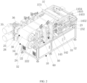
FIG. 2 is a schematic structural diagram of the rear view of the dry electrode double steel belt apparatus for forming free-standing films according toFIG. 1 ; -
FIG. 3 is a schematic front view of the dry electrode double steel belt apparatus for forming free-standing films according toFIG. 1 ; -
FIG. 4 is a schematic sectional view of the dry electrode double steel belt apparatus for forming free-standing films according toFIG. 1 ; and -
FIG. 5 is a schematic structural view of the dry electrode double steel belt apparatus for forming free-standing films according toFIG. 1 in the absence of the bottom steel belt, the top steel belt, the top driven roller, the bottom heating module and the top heating module. - In the following, the concept, specific structure and technical effects of the disclosure will be clearly and completely described with embodiments and drawings, so as to fully explain the purpose, features and effects of the disclosure. Obviously, the described embodiment is only a part of the embodiment of the present disclosure. Based on the embodiment of the present disclosure, other embodiments obtained by those skilled in the art without creative labors are included in the protection scope of the present disclosure. In addition, all the coupling/connecting relationships involved in the disclosure do not mean that two components are directly connected, but that a better connection structure between the two components can be formed by adding or reducing connecting accessories according to specific implementation conditions. Various technical features in the disclosure can be combined interactively on the premise of not conflicting with each other.
- Referring to
FIG. 1 to FIG. 5 , according to an embodiment of the present disclosure, a dry electrode double steel belt apparatus for forming free-standing films includes aframe 10, a bottomsteel belt mechanism 20, a topsteel belt mechanism 30 arranged above the bottomsteel belt mechanism 20, aheating mechanism 40 and a calendering mechanism. The bottomsteel belt mechanism 20, the topsteel belt mechanism 30, theheating mechanism 40 and the calendering mechanism are arranged on theframe 10. - As shown in
FIG. 1 to FIG. 3 , theframe 10 includes abase 12 and two side frames. The two side frames are respectively arranged at the front side and the rear side of the top end of thebase 12. - Each side frame includes a
mounting plate 142, afirst part 143 and a second part, respectively. Themounting plates 142 of the two side frames are respectively arranged at the front side and the rear side of the top end of thebase 12, and are oppositely arranged in front and rear. Thefirst part 143 and the second part are arranged side by side along the length direction of theframe 10. Thefirst part 143 is a rectangular frame with two openings, which is proximate to the left end of thebase 12. Thefirst part 143 has a first mounting space and a second mounting space, which are arranged side by side along the length direction of theframe 10. The first mounting space is proximate to the second part, and the second mounting space is arranged between the first mounting space and the left end of thebase 12. The second part includes avertical plate 1452, a bottomtransverse plate 1453, a toptransverse plate 1454 and aninclined plate 1455. The bottomtransverse plate 1453 and the toptransverse plate 1454 are sequentially arranged above thecorresponding mounting plates 142. Thevertical plate 1452 is arranged at the top end of thecorresponding mounting plate 142. Thevertical plate 1452 is arranged proximate to the right end of thebase 12. One end of the bottomtransverse plate 1453 is arranged at the right end of thefirst part 143, and the other end of the bottomtransverse plate 1453 is arranged at the top end of thevertical plate 1452. One end of the toptransverse plate 1454 is arranged at the right end of thefirst part 143, and the other end of the toptransverse plate 1454 is arranged at the top end of theinclined plate 1455, and the bottom end of theinclined plate 1455 is arranged at the top end of thevertical plate 1452. - The top
steel belt mechanism 20 includes abottom driving roller 22, a bottom drivenroller 23, abottom steel belt 24 sleeved on thebottom driving roller 22 and the bottom drivenroller 23, and a bottom driving module for driving thebottom driving roller 22 to rotate. - Both ends of the
bottom driving roller 22 are respectively arranged at the left ends of the twofirst parts 143 with two bearingseats 222. Both ends of the bottom drivenroller 23 are respectively arranged at the top ends of the twomounting plates 142 with two bearingseats 232. Thebottom driving roller 22 is proximate to the left end of thebase 12, and the bottom drivenroller 23 is proximate to the right end of thebase 12. The bottom drivenroller 23 and thebottom driving roller 22 are of the same size, and the center of the bottom drivenroller 23 and the center of thebottom driving roller 22 are horizontally arranged, so that thebottom steel belt 24 is horizontally arranged. The bottom driving module comprises abottom driving motor 25 and abottom reducer 26, wherein thebottom driving motor 25 is arranged on thebottom reducer 26, and thebottom reducer 26 is arranged at the left end of one of thefirst parts 143. The output end of thebottom driving motor 25 is connected with the input end of thebottom reducer 26, and the output end of thebottom reducer 26 is connected with one end of thebottom driving roller 22. As a driving roller, thebottom driving roller 22 can drive the bottom drivenroller 23 to rotate under the action of thebottom steel belt 24 when thebottom driving motor 25 drives thebottom driving roller 22 to rotate through thebottom reducer 26. In this embodiment, thebottom driving roller 22 rotates in the counterclockwise direction, so that thebottom steel belt 24 rotates in the counterclockwise direction, that is, it circulates in the counterclockwise direction, and the bottom drivenroller 23 also rotates in the counterclockwise direction. - As shown in
FIG. 1 andFIG. 4 , afeeding area 70 is arranged above the bottom drivenroller 23 and thebottom steel belt 24, and electrode powder (which is the positive and negative electrode materials of the dry electrode of lithium battery) can be added to thebottom steel belt 24 through the feedingarea 70, so that the electrode powder can be driven to move towards the direction proximate to thebottom driving roller 22 and thetop driving roller 32 through thebottom steel belt 24. - In this embodiment, two baffles 72 are arranged above the bottom driven
roller 23 and thebottom steel belt 24, which are opposite to each other in front and rear. The length direction of the baffles 72 is the same as that of theframe 10, and the above-mentionedfeeding area 70 is formed between the two baffles 72. The width of thefeeding area 70 corresponds to the width of thebottom steel belt 24. The two baffles 72 are respectively arranged on two connecting plates 73, the top ends of the two connecting plates 73 are provided with two connectingrods 74, and the two ends of the connectingrods 74 are respectively arranged on the two bottomtransverse plates 1453 of the second part. - The bottom driven
roller 23 is provided with a bottom heating module on a side distal from thebottom driving roller 22. The bottom heating module is used to heat thebottom steel belt 24, so that the electrode powder added to thebottom steel belt 24 through the feedingarea 70 can be heated. The temperature of thebottom steel belt 24 to heat the electrode powder is 160-200°C, preferably 180°C, and the electrode powder can be heated through thebottom steel belt 24, so that the adhesive in the electrode powder can be activated and that the electrode powder can be extruded into a free-standing film at high temperature. - As shown in
FIG. 1 andFIG. 4 , the bottom heating module includes abottom heating cover 27 and abottom heating tube 272 arranged at the top end of thebase 12. One side of thebottom heating cover 27 proximate to the bottom drivenroller 23 has an arc surface, and thebottom heating cover 27 surrounds the outer periphery of the bottom drivenroller 23 through the arc surface. Thebottom heating cover 27 is slightly higher than thebottom steel belt 24 vertically. The side of thebottom heating cover 27 proximate to the bottom drivenroller 23 has an opening (or is opened) which corresponds to thebottom steel belt 24. A gap exists between the side of thebottom heating cover 27 proximate to the drivenroller 23 and thebottom steel belt 24, so that thebottom heating cover 27 is not in contact with thebottom steel belt 24. Abottom mounting part 271 is arranged in thebottom heating cover 27, and thebottom mounting part 271 is arc-shaped. Both ends of thebottom mounting part 271 are arranged on the inner walls of both sides of thebottom heating cover 27, and thebottom mounting part 271 surrounds the outer periphery of the bottom drivenroller 23, and a gap exists between thebottom mounting part 271 and thebottom steel belt 24. Abottom heating tube 272, such as an electric heating tube, is arranged in thebottom mounting part 271. One end of thebottom heating tube 272 is used to connect with an external power supply through a wire, and a through hole for the wire to pass through is arranged on the outer wall of one side of thebottom heating cover 27. There are a plurality ofbottom heating tubes 272, which are distributed at intervals along the circumferential direction of thebottom mounting part 271. The number ofbottom heating tubes 272 can be adjusted according to actual needs. Thebottom heating tube 272 generates heat after being electrified, so that thebottom steel belt 24 can be heated. - In this embodiment, both ends of the bottom driven
roller 23 are slidably arranged at the top ends of the two mountingplates 142 with two bearingseats 232, respectively. Both ends of the bottom drivenroller 23 can slide left and right at the top ends of the two mountingplates 142 with two bearingseats 232. Specifically, the top ends of the two mountingplates 142 are respectively provided with bottom slide rails, and the two bearingseats 232 are respectively slidably matched with the bottom slide rails on the two mountingplates 142 and can slide left and right along the corresponding bottom slide rails, thereby driving the bottom drivenroller 23 to slide left and right. - The top ends of the two mounting
plates 142 are respectively provided withbottom tensioning cylinders 28, and the cylinder shafts of the twobottom tensioning cylinders 28 are respectively connected with the two bearingseats 232, so that the two bearingseats 232 can be driven to slide left and right by the twobottom tensioning cylinders 28 and that the bottom drivenroller 23 can be driven to slide left and right. The tension of thebottom steel belt 24 can be adjusted by thebottom tensioning cylinder 28, so that thebottom steel belt 24 can be tensioned. - The top
steel belt mechanism 30 includes atop driving roller 32, a top drivenroller 33, atop steel belt 34 sleeved on thetop driving roller 32 and the top drivenroller 33, and a top driving module for driving thetop driving roller 32 to rotate. - Both ends of the
top driving roller 32 are respectively arranged at the left ends of the twofirst parts 143 with two bearing seats 322. Thetop driving roller 32 corresponds to thebottom driving roller 22. The two ends of the top drivenroller 33 are respectively arranged at the top ends of the bottomtransverse plates 1453 of the two second parts with two bearingseats 332. The top drivenroller 33 is arranged between thetop driving roller 32 and the bottom drivenroller 23. A gap exists between thetop steel belt 34 and thebottom steel belt 24. The top drivenroller 33 and thetop driving roller 32 are of the same size, and the center of the top drivenroller 33 is arranged above the center of thetop driving roller 32, so that thetop steel belt 34 is obliquely arranged relative to thebottom steel belt 24. Therefore, the width of the gap between thetop steel belt 34 and thebottom steel belt 24 gradually decreases along the direction from the top drivenroller 33 to thetop driving roller 32. The top driving module comprises atop driving motor 35 and atop reducer 36, wherein thetop driving motor 35 is arranged on thetop reducer 36, and thetop reducer 36 is arranged at the left end of one of thefirst parts 143. The output end of thetop driving motor 35 is connected with the input end of thetop reducer 36, and the output end of thetop reducer 36 is connected with one end of thetop driving roller 32. Thetop drive motor 35 corresponds to thebottom drive motor 25, and thetop reducer 36 corresponds to thebottom reducer 26. Thetop driving roller 32 is a driving roller, the top drivenroller 33 is a driven roller, and thetop steel belt 34 is a synchronous strip. When thetop driving motor 35 drives thetop driving roller 32 to rotate through thetop reducer 36, the top drivenroller 33 can be driven to rotate under the action of thetop steel belt 34. The rotation direction of thetop driving roller 32 is opposite to that of thebottom driving roller 22, so that the rotation direction of thetop steel belt 34 is opposite to that of thebottom steel belt 24, and the rotation direction of the top drivenroller 33 is opposite to that of the bottom drivenroller 23. In this embodiment, thetop driving roller 32 rotates in the clockwise direction, so that thetop steel belt 34 rotates in the clockwise direction, that is, it circulates in the clockwise direction, and the top drivenroller 33 also rotates in the clockwise direction. The rotation speed of thetop driving roller 32 is the same as that of thebottom driving roller 22, so that the rotation speed of thetop steel belt 34 is the same as that of thebottom steel belt 24, and that the rotation speed of the top drivenroller 33 is the same as that of the bottom drivenroller 23. In practical application, when the electrode powder, driven by thebottom steel belt 24, enters the gap between thetop steel belt 34 and thebottom steel belt 24, the electrode powder can be extruded by the interaction between thetop steel belt 34 and thebottom steel belt 24, so that the electrode powder forms an electrode free-standing film, and that the formed electrode free-standing film, driven by thetop steel belt 34 and thebottom steel belt 24, can move towards the direction proximate to thetop driving roller 32 and thebottom driving roller 22. - A side of the top driven
roller 33 distal from thetop driving roller 32 is provided with a top heating module. The top heating module is used to heat thetop steel belt 34, so that when the electrode powder, driven by thebottom steel belt 24, enters the gap, the electrode powder can be heated by thetop steel belt 34 at a temperature of 160-200°C, preferably of 180°C, and the electrode powder can be heated by thetop steel belt 34, so that the adhesive in the electrode powder can be activated, facilitating for the electrode powder to be extruded into a free-standing film at high temperature. - As shown in
FIG. 4 , the top heating module includes atop heating cover 37 and atop heating tube 372. Thetop heating cover 37 is arc-shaped and surrounds the outer periphery of the top drivenroller 33. Thetop heating cover 37 is slightly higher than thetop steel belt 34 vertically. One side of thetop heating cover 37 proximate to the top drivenroller 33 has an opening (or is opened), which corresponds to thetop steel belt 34. A gap exists between the side of thetop heating cover 37 proximate to the drivenroller 33 and thetop steel belt 34, so that thetop heating cover 37 is not in contact with thetop steel belt 34. Thetop heating cover 37 is arranged at the top ends of the toptransverse plates 1454 of the two second parts with mountingpieces 373, as shown inFIG. 1 andFIG. 4 . Thetop heating cover 37 is provided with a top mountingpart 371, which is arc-shaped. Both ends of the top mountingpart 371 are arranged on the inner walls of both sides of thetop heating cover 37, and thetop mounting part 371 surrounds the outer periphery of the top drivenroller 33, and a gap exists between the top mountingpart 371 and thetop steel belt 34. Thetop heating tube 372, such as an electric heating tube, is arranged in thetop mounting part 371. One end of thetop heating tube 372 is used for connecting with an external power supply through a wire, and a through hole for the wire to pass through is arranged on the outer wall of one side of thetop heating cover 37. There are a plurality oftop heating tubes 372, which are distributed at intervals along the circumferential direction of the top mountingpart 371. The number oftop heating tubes 372 can be adjusted according to actual needs. Thetop heating tube 372 generates heat after being electrified, so that thetop steel belt 34 can be heated. - In this embodiment, both ends of the top driven
roller 33 are slidably arranged at the top ends of the bottomtransverse plates 1453 of the two second parts with two bearingseats 332 respectively. The two ends of the top drivenroller 33 can slide left and right at the top ends of the bottomtransverse plates 1453 of the two second parts with two bearingseats 332. Specifically, the top ends of the bottomtransverse plates 1453 of the two second parts are respectively provided with top slide rails, and the two bearingseats 332 are respectively slidably matched with the top slide rails on the bottomtransverse plates 1453 of the two second parts and can slide left and right along the corresponding top slide rail, thereby driving the top drivenroller 33 to slide left and right. - The top ends of the bottom
transverse plates 1453 of the two second parts are respectively provided withtop tensioning cylinders 38, and the cylinder shafts of the twotop tensioning cylinders 38 are respectively connected with the two bearingseats 332, so that the two bearingseats 332 can be driven to slide left and right by the twotop tensioning cylinders 38, and that the top drivenroller 33 can be driven to slide left and right. The tension of thetop steel belt 34 can be adjusted by thetop tensioning cylinder 38, so that thetop steel belt 34 can be tensioned. - As shown in
FIG. 4 andFIG. 5 , theheating mechanism 40 is arranged at the inner side of thebottom steel belt 24 and below the top drivenroller 33. Theheating mechanism 40 is used to heat thebottom steel belt 24. Theheating mechanism 40 heats thebottom steel belt 24 at a temperature of 160-200°C, preferably of 180°C. During the process that thebottom steel belt 24 drives the electrode powder to move towards the direction proximate to thebottom driving roller 22 and thetop driving roller 32, thebottom steel belt 24 is heated by theheating mechanism 40. Therefore, the electrode powder can be heated by thebottom steel belt 24, so that the temperature of the electrode powder can be kept constant, and that the electrode powder can be extruded into a free-standing film by thetop steel belt 34 and thebottom steel belt 24. - In this embodiment, there are three
heating mechanisms 40, and the threeheating mechanisms 40 are sequentially arranged at intervals in the direction proximate to thebottom driving roller 22. It can be understood that the number ofheating mechanisms 40 can be adjusted according to actual needs. Among the threeheating mechanisms 40, thefirst heating mechanism 40 is proximate to the left end of thefeeding area 70, thesecond heating mechanism 40 is arranged below the top drivenroller 33, and thethird heating mechanism 40 is arranged on the side of the top drivenroller 33 distal from thetop heating cover 37. - The
heating mechanism 40 includes abracket 42 and asquare heater 43 arranged at the top end of thebracket 42. Both ends of thebracket 42 are respectively arranged on two transverse connectingplates 14532, which are respectively arranged on two bottomtransverse plates 1453 of the two second parts. There are threeheaters 43, which are arranged side by side along the length direction of thebracket 42. It can be understood that the number ofheaters 43 can be adjusted according to actual needs. - The
heater 43 is preferably a ceramic heater, and thebottom steel belt 24 can be heated by the ceramic heater. It should be appreciated that theheater 43 can also be other types of heaters. - In this embodiment, four passing
rollers 44 are arranged in sequence along the direction from the bottom drivenroller 23 to thebottom driving roller 22. As shown inFIG. 4 , thebottom steel belt 24 passes through the four passingrollers 44, which are proximate to the bottom drivenroller 23 to support thebottom steel belt 24. After the electrode powder is added to thebottom steel belt 24 through the feedingarea 70, thebottom steel belt 24 will generally deform downward under the gravity of the electrode powder. In order to address the problem of deformation of thebottom steel belt 24, the four passingrollers 44 are provided to support thebottom steel belt 24, so that thebottom steel belt 24 can be ensured to be in a horizontal state. Aheating mechanism 40 described above is arranged between two adjacent passingrollers 44. Two ends of the passingroller 44 are respectively arranged on two transverse connectingplates 14532 with two bearing seats 442. It should be appreciated that the number of passingrollers 44 can be adjusted according to actual needs. - As shown in
FIG. 4 ,scraper plates 80 are respectively arranged at thebottom driving roller 22, the bottom drivenroller 23, thetop driving roller 32, the top drivenroller 33, the inner side of thebottom steel belt 24 and the inner side of thetop steel belt 34, and the arrangedscraper plates 80 can scrape the electrode powder on the corresponding roller and on the inner side of the corresponding steel strip. - The calendering mechanism is arranged between the
bottom driving roller 22, thetop driving roller 32 and the top drivenroller 33, and is used for extruding the electrode free-standing film to realize the compaction, thinning and correction of the electrode free-standing film. - Specifically, as shown in
FIG. 1 to FIG. 4 , the calendering mechanism includes two two-roll calendering assemblies, namely, a first two-roll calendering assembly and a second two-roll calendering assembly, and the first two-roll calendering assembly is arranged between the top drivenroller 33 and the second two-roll calendering assembly. - The first two-roll calendering assembly includes a first
bottom calendering roller 52, a firsttop calendering roller 53 and two first driving modules. The firsttop calendering roller 53 is arranged above the firstbottom calendering roller 52 and is vertically opposite to the firstbottom calendering roller 52. Both ends of the firstbottom calendering roller 52 are fixedly arranged at the bottoms of the first mounting spaces of the twofirst parts 143 with two bearingseats 522, so that the firstbottom calendering roller 52 is relatively fixed with theframe 10. The firstbottom calendering roller 52 is arranged at the inner side of thebottom steel belt 24 and abuts against thebottom steel belt 24. Both ends of the firsttop calendering roller 53 are slidably arranged on the inner walls of the first mounting spaces of the twofirst parts 143 with two bearingseats 532, and the firsttop calendering roller 53 can slide up and down in the first mounting spaces of the twofirst parts 143, so that the firsttop calendering roller 53 can slide up and down relative to theframe 10. Specifically, the left end and the right end of eachbearing seat 532 are in sliding fit with twoslide rails 533 respectively, and the twoslide rails 533 are respectively arranged on two inner walls of the corresponding first mounting spaces, and eachbearing seat 532 can slide up and down along the corresponding twoslide rails 533, thereby driving the firsttop calendering roller 53 to slide up and down. The firsttop calendering roller 53 is arranged at the inner side of thetop steel belt 34 and abuts against thetop steel belt 34. In practical application, since the firstbottom calendering roller 52 and the firsttop calendering roller 53 abut against thebottom steel belt 24 and thetop steel belt 34 respectively, and the width of the gap between thetop steel belt 34 and thebottom steel belt 24 gradually decreases along the direction from the top drivenroller 33 to thetop driving roller 32, so that the electrode free-standing film can be extruded for the first time by the firstbottom calendering roller 52 and the firsttop calendering roller 53 to realize the first compaction, thinning and correction of the electrode free-standing film. - The first
bottom calendering roller 52 and the firsttop calendering roller 53 are heating rollers, so that thebottom steel belt 24 and thetop steel belt 34 can be heated by the firstbottom calendering roller 52 and the firsttop calendering roller 53, and that the electrode free-standing film can be heated to activate the adhesive, facilitating for extruding the electrode free-standing film. One end of the firstbottom calendering roller 52 and one end of the firsttop calendering roller 53 are respectively provided with conductive slip rings with conductive slip ring seats, and the heating tubes of the firstbottom calendering roller 52 and the firsttop calendering roller 53 can be electrically connected with an external power supply through corresponding conductive slip rings, so that when the heating tubes of the firstbottom calendering roller 52 and the firsttop calendering roller 53 are electrified, thebottom steel belt 24 and thetop steel belt 34 can be heated. - The two first driving modules are used to drive the first
top calendering roller 53 to slide up and down. The two first driving modules respectively correspond to the two bearingseats 532. - The first driving module includes a first connecting
block 54, a first threadedrod nut 55, a first threadedrod 56 and a first drivingmember 57. The first connectingblock 54 is arranged at the top end of the corresponding bearingseat 532. The top end of the first connectingblock 54 is provided with an approximately rectangular mounting hole, and the bottom end of the first threadedrod nut 55 is arranged in the mounting hole. The first threadedrod 56 is threadedly engaged with the first threadedrod nut 55, and the first threadedrod 56 partially extends out of the top end of the first threadedrod nut 55. The top end of the first threadedrod 56 protrudes from the through hole at the top of the corresponding first mounting space and is connected with the first drivingmember 57. A bearing is arranged in the through hole, and the bearing is sleeved on the outer periphery of the first threadedrod 56 to provide rotational support for the first threadedrod 56. The first drivingmember 57 is a handwheel, and it should be appreciated that the first drivingmember 57 can also be a motor. In practical application, by rotating the handwheel, the first threadedrod 56 can be driven to rotate, and the rotation of the first threadedrod 56 can drive the first threadedrod nut 55 to move up and down, thus driving the first connectingblock 54 to move up and down, further driving the corresponding bearingseat 532 to slide up and down along the corresponding twoslide rails 533, and further driving the firsttop calendering roller 53 to slide up and down. In practical application, by sliding the firsttop calendering roller 53 up and down, the distance between the firsttop calendering roller 53 and the firstbottom calendering roller 52 can be adjusted according to the required thickness of the electrode free-standing film, and then the width of the gap between thetop steel belt 34 and thebottom steel belt 24 can be adjusted, so that when the electrode free-standing film is extruded by the firsttop calendering roller 53 and the firstbottom calendering roller 52, the electrode free-standing film with the required thickness can be obtained. - The first connecting
block 54 includes a connecting seat, a load sensor and a pressing plate which are arranged in sequence from bottom to top. The connecting seat, the load sensor and the pressing plate are of a circular shape, and the connecting seat is arranged at the top end of the corresponding bearingseat 532, and the top end of the pressing plate is provided with the above-mentioned mounting hole. The load sensor can measure the pressing force of the firstbottom calendering roller 52 and the firsttop calendering roller 53 exerted on the electrode free-standing film. - As shown in
FIG. 1 andFIG. 3 , the first two-roll calendering assembly further includes twofirst dial indicators 58, which are respectively arranged at the top ends of the twofirst parts 143. The top ends of the first connectingblocks 54 of the two first driving modules are respectively provided with two first connectingpieces 542, which are Z-shaped and arranged between the twofirst parts 143, and eachfirst dial indicator 58 corresponds to one first connectingpiece 542. The end of a measuring rod of thefirst dial indicator 58 abuts against the top end of the corresponding first connectingpiece 542, and the up-and-down sliding distance of the firsttop calendering roller 53 can be measured by thefirst dial indicator 58, facilitating the operator to adjust an accurate distance between the firsttop calendering roller 53 and the firstbottom calendering roller 52. - The
first dial indicator 58 may be replaced by, for example, other dial indicators with different precision. - The structure of the second two-roll calendering assembly is the same as that of the first two-roll calendering assembly. The second two-roll calendering assembly includes a second
bottom calendering roller 62, a secondtop calendering roller 63 and two second driving modules. The secondtop calendering roller 63 is arranged above the secondbottom calendering roller 62 and is vertically opposite to the secondbottom calendering roller 62. The two ends of the secondbottom calendering roller 62 and the two ends of the secondbottom calendering roller 62 are respectively fixedly arranged at the bottoms of the second mounting spaces of the twofirst parts 143 with two bearingseats 622, so that the secondbottom calendering roll 62 is relatively fixed with theframe 10. The secondbottom calendering roller 62 is arranged at the inner side of thebottom steel belt 24 and abuts against thebottom steel belt 24. Two ends of the secondtop calendering roller 63 are slidably arranged on the inner walls of the second mounting spaces of the twofirst parts 143 through two bearingseats 632, and the secondtop calendering roller 63 can slide up and down in the second mounting spaces of the twofirst parts 143, so that the secondtop calendering roller 63 can slide up and down relative to theframe 10. Specifically, the left end and the right end of eachbearing seat 632 are in sliding fit with twoslide rails 633 respectively, and the twoslide rails 633 are respectively arranged on the two inner walls of the corresponding second mounting spaces, and eachbearing seat 632 can slide up and down along the corresponding twoslide rails 633, thereby driving the secondtop calendering roller 63 to slide up and down. The secondtop calendering roller 63 is arranged at the inner side of thetop steel belt 34 and abuts against thetop steel belt 34. In practical application, the secondbottom calendering roller 62 and the firsttop calendering roller 63 abut against thebottom steel belt 24 and thetop steel belt 34 respectively, and the width of the gap between thebottom steel belt 24 and the top steel belt gradually decreases along the direction from the top drivenroller 33 to thetop driving roller 32, so that the electrode free-standing film can be extruded for the second time by the firstbottom calendering roller 62 and the firsttop calendering roller 63 to realize the second compaction, thinning and correction of the thickness of the electrode free-standing film, and thus the required electrode free-standing film can be obtained. - The second
bottom calendering roller 62 and the secondtop calendering roller 63 are heating rollers, so that thebottom steel belt 24 and thetop steel belt 34 can be heated by the secondbottom calendering roller 62 and the secondtop calendering roller 63, and that the electrode free-standing film can be heated to activate the adhesive, facilitating for extruding the electrode free-standing film. One end of the secondbottom calendering roller 62 and one end of the secondtop calendering roller 63 are respectively provided with conductive slip rings through conductive slip ring seats, and the heating tubes of the secondbottom calendering roller 62 and the secondtop calendering roller 63 can be electrically connected with an external power supply through corresponding conductive slip rings. When the heating tubes of the secondbottom calendering roller 62 and the secondtop calendering roller 63 are electrified, thebottom steel belt 24 and thetop steel belt 34 can be heated. - Two second drive modules are used to drive the second
top calendering roller 63 to slide up and down. The two second driving modules correspond to the two bearingseats 632, respectively. - The second driving module includes a second connecting
block 64, a second threadedrod nut 65, a second threadedrod 66 and asecond driving member 67. The second connectingblock 64 is arranged at the top end of the corresponding bearingseat 632. The top end of the second connectingblock 64 is provided with an approximately rectangular mounting hole, and the bottom end of the second threadedrod nut 65 is arranged in the mounting hole. The second threadedrod 66 is threadedly engaged with the second threadedrod nut 65. The second threadedrod 66 partially extends out of the top end of the second threadedrod nut 65, and the top end of the threadedrod 66 protrudes from the through hole at the top of the corresponding second mounting space and is connected with the second drivingmember 67. A bearing is arranged in the through hole, and the bearing is sleeved on the periphery of the second threadedrod 66 to provide rotational support for the second threadedrod 66. Thesecond driving member 67 is a handwheel, and it should be appreciated that the second drivingmember 67 can also be a motor. In practical application, by rotating the handwheel, the second threadedrod 66 can be driven to rotate, and the rotation of the second threadedrod 66 can drive the second threadedrod nut 65 to move up and down, thus driving the second connectingblock 64 to move up and down, further driving the corresponding bearingseat 632 to slide up and down along the corresponding twoslide rails 633, and further driving the secondtop calendering roller 63 to slide up and down. In practical application, by sliding the secondtop calendering roller 63 up and down, the distance between the secondtop calendering roller 63 and the secondbottom calendering roller 62 can be adjusted according to the actual required thickness of the electrode free-standing film, and then the width of the gap between thetop steel belt 34 and thebottom steel belt 24 can be adjusted, so that when the electrode free-standing film is extruded by the secondtop calendering roller 63 and the secondbottom calendering roller 62, the electrode free-standing film with the required thickness can be obtained. - The second connecting
block 64 includes a connecting seat, a load sensor and a pressing plate which are arranged in sequence from bottom to top. The connecting seat, the load sensor and the pressing plate are all of a circular shape, and the connecting seat is arranged at the top end of the corresponding bearingseat 632, and the top end of the pressing plate is provided with the above-mentioned mounting hole. The load sensor can measure the pressing force of the secondbottom calendering roller 62 and the secondtop calendering roller 63 exerted on the electrode free-standing film. - As shown in
FIG. 1 andFIG. 3 , the second two-roll calendering assembly further includes twosecond dial indicators 68, which are respectively arranged at the top ends of the twofirst parts 143. The top ends of the second connectingblocks 64 of the two second driving modules are respectively provided with two second connectingpieces 642, which are Z-shaped and arranged between the twofirst parts 143, and eachsecond dial indicator 68 corresponds to one second connectingpiece 642. The end of a measuring rod of thesecond dial indicator 68 abuts against the top end of the corresponding second connectingpiece 642, and the up-and-down sliding distance of the secondtop calendering roller 63 can be measured by thesecond dial indicator 68, facilitating the operator to adjust the accurate distance between the secondtop calendering roller 63 and the secondbottom calendering roller 62. - The
second dial indicator 68 may be replaced by, for example, other dial indicators with different precision. - It should be appreciated that, in other embodiments, the number of two-roll calendering assemblies can be three, four, or more than four, that is, the number of two-roll calendering assemblies can be adjusted according to actual needs.
- From the above structure, the working principle of the disclosure is as follows: firstly, the
bottom driving roller 22 is driven to rotate counterclockwise by the bottom driving module, so that thebottom steel belt 24 and the bottom drivenroller 23 rotate counterclockwise, and at the same time, thetop driving roller 32 is driven to rotate synchronously by the top driving module, so that thetop steel belt 34 and the top drivenroller 33 rotate clockwise. Thebottom steel belt 24 and thetop steel belt 34 are heated by the bottom heating module and the top heating module respectively. Secondly, the electrode powder is added to thebottom steel belt 24 through the feedingarea 70. With thebottom steel belt 24 being heated by the bottom heating module, the electrode powder is heated by thebottom steel belt 24 to activate the adhesive in the electrode powder. Meanwhile, the electrode powder can be driven to move towards the direction proximate to thebottom driving roller 22 and thetop driving roller 32 by thebottom steel belt 24, and thebottom steel belt 24 is heated by theheating mechanism 40 during the process of driving the electrode powder to move towards the direction proximate to thebottom driving roller 22 and thetop driving roller 32, so that the electrode powder can be heated by thebottom steel belt 24 at a constant temperature. When the electrode powder enters the gap between thetop steel belt 34 and thebottom steel belt 24, as thetop steel belt 34 is heated by the top heating module, the electrode powder can be heated by thetop steel belt 34 to activate the adhesive in the electrode powder, and at the same time, the electrode powder is extruded by thetop steel belt 34 and thebottom steel belt 24 to form an electrode free-standing film. The formed electrode free-standing film can be driven by thetop steel belt 34 and thebottom steel belt 24 to move towards the direction proximate to thebottom driving roller 22 and thetop driving roller 32. Thirdly, during the movement of the electrode free-standing film, the electrode free-standing film is first extruded by the firstbottom calendering roller 52 and the firsttop calendering roller 53 of the first two-roll calendering assembly. Since the width of the gap between thetop steel belt 34 and thebottom steel belt 24 gradually decreases along the direction from the top drivenroller 33 to thetop driving roller 32, the electrode free-standing film can be compacted, thinned and corrected for the first time by the firstbottom calendering roller 52 and the firsttop calendering roller 53. Next, the electrode free-standing film is extruded for the second time by the secondbottom calendering roller 62 and the secondtop calendering roller 63 of the second two-roll calendering assembly, so that the electrode free-standing film can be compacted, thinned and corrected for the second time, and the required electrode free-standing film can be obtained. Besides, during the extrusion of the electrode free-standing film by the firstbottom calendering roller 52 and the firsttop calendering roller 53 and during the extrusion of the electrode free-standing film by the secondbottom calendering roller 62 and the secondtop calendering roller 63, the electrode free-standing film can also be heated by the firstbottom calendering roller 52 and the firsttop calendering roller 53, the secondbottom calendering roller 62 and the secondtop calendering roller 63, so as to facilitate the extrusion of the electrode free-standing film. - According to the disclosure, with the combination of the bottom
steel belt mechanism 20, the topsteel belt mechanism 30, theheating mechanism 40 and the calendering mechanism, the present apparatus, with the use of electrode powder, realizes continuous production and one-step calender of a free-standing film that is not easy to break, achieving the mass production and thus improving the production efficiency and reducing the production cost. - Based on the dry electrode double steel belt apparatus for forming free-standing films, the disclosure also provides a dry electrode double steel belt free-standing film-forming method, which comprises the following steps:
- step S1: driving the
bottom driving roller 22 to rotate counterclockwise by thebottom driving motor 25 and thebottom reducer 26 of the bottom driving module, thereby rotating thebottom steel belt 24 and the bottom drivenroller 23 counterclockwise; meanwhile, synchronously driving thetop driving roller 33 to rotate in the opposite direction by thetop driving motor 35 and thetop reducer 36 of the top driving module, that is, clockwise, thereby rotating thetop steel belt 34 and the top drivenroller 33 in the opposite direction, that is, clockwise; - step S2, heating the
bottom steel belt 24 by thebottom heating tube 272 of the bottom heating module, and heating thetop steel belt 34 by thetop heating tube 372 of the top heating module; - step S3: adding an electrode powder to the
bottom steel belt 24 through afeeding area 70; as thebottom steel belt 24 is heated by the bottom heating module, the electrode powder can be heated by thebottom steel belt 24 to activate the adhesive in the electrode powder; meanwhile, driving the electrode powder to move towards the direction proximate to thebottom driving roller 22 and thetop driving roller 32 by thebottom steel belt 24; and heating the electrode powder by thebottom steel belt 24 at a temperature of 160-200°C, preferably of 180°C.
during the process that thebottom steel belt 24 drives the electrode powder to move towards the direction proximate to thebottom driving roller 22 and thetop driving roller 32, heating thebottom steel belt 24 by theheater 43 of theheating mechanism 40, so that the electrode powder can be heated by thebottom steel belt 24 at a constant temperature; and heating thebottom steel belt 24 by theheater 43 of theheating mechanism 40 at a temperature of 160-200°C, preferably of 180°C. - step S4: when the electrode powder enters the gap between the
top steel belt 34 and thebottom steel belt 24, as thetop steel belt 34 is heated by the top heating module, heating the electrode powder by thetop steel belt 34 to activate the adhesive in the electrode powder; meanwhile, extruding the electrode powder by thetop steel belt 34 and thebottom steel belt 24 to form an electrode free-standing film, and driving the formed electrode free-standing film by thetop steel belt 34 and thebottom steel belt 24 to move towards the direction proximate to thebottom driving roller 22 and thetop driving roller 32; and heating the electrode powder by thetop steel belt 34 at a temperature of 160-200°C, preferably of 180°C. - step S5: during the movement of the electrode free-standing film, extruding the electrode free-standing film for the first time by the first
bottom calendering roller 52 and the firsttop calendering roller 53 of the first two-roll calendering assembly of the calendering mechanism; since the width of the gap between thetop steel belt 34 and thebottom steel belt 24 gradually decreases along the direction from the top drivenroller 33 to thetop driving roller 32, the electrode free-standing film can be compacted, thinned and corrected for the first time by the firstbottom calendering roller 52 and the firsttop calendering roller 53; next, extruding the electrode free-standing film for the second time by the secondbottom calendering roller 62 and the secondtop calendering roller 63 of the second two-roll calendering assembly of the calendering mechanism, so that the electrode free-standing film can be compacted, thinned and corrected for the second time to obtain the required electrode free-standing film. - The above is a detailed description of the preferred embodiments of the present disclosure, but the disclosure is not limited to the embodiment, and those skilled in the art can make various equivalent deformations or substitutions without violating the spirit of the present disclosure, which are included in the scope defined by the claims of this disclosure.
Claims (13)
- A dry electrode double steel belt apparatus for forming free-standing films comprises a frame (10), and is characterized by comprising a bottom steel belt mechanism (20), a top steel belt mechanism (30) arranged above the bottom steel belt mechanism (20), a heating mechanism (40) and a calendering mechanism;the bottom steel belt mechanism (20) comprises a bottom driving roller (22), a bottom driven roller (23) and a bottom steel belt (24) sleeved on the bottom driving roller (22) and the bottom driven roller (23), wherein the bottom driving roller (22) and the bottom driven roller (23) are respectively arranged on the frame (10); a feeding area (70) is arranged above the bottom driven roller (23) and the bottom steel belt (24), and a bottom heating module is arranged on one side of the bottom driven roller (23) distal from the bottom driving roller (22);the top steel belt mechanism (30) comprises a top driving roller (32), a top driven roller (33) and a top steel belt (34) sleeved on the top driving roller (32) and the top driven roller (33), wherein the top driving roller (32) and the top driven roller (33) are respectively arranged on the frame (10), the top driving roller (32) corresponds to the bottom driving roller (22), the top driven roller (33) is arranged between the top driving roller (32) and the feeding area (70), and a gap exists between the top steel belt (34) and the bottom steel belt (24), and the width of the gap gradually decreases along the direction from the top driven roller (33) to the top driving roller (32); and a top heating module is arranged on one side of the top driven roller (33) distal from the top driving roller (32);the heating mechanism (40) is arranged at the inner side of the bottom steel belt (24) and below the top driven roller (33); andthe calendering mechanism is arranged between the bottom driving roller (22), the top driving roller (32) and the top driven roller (33).
- The dry electrode double steel belt apparatus for forming free-standing films according to claim 1, characterized in that the bottom steel belt mechanism (20) further comprises a bottom driving module for driving the bottom driving roller (22) to rotate, and the bottom driving module comprises a bottom driving motor (25) and a bottom reducer (26) connected with the bottom driving motor (25), and the bottom reducer (26) is connected with one end of the bottom driving roller (22).
- The dry electrode double steel belt apparatus for forming free-standing films according to claim 1, characterized in that the top steel belt mechanism (30) further comprises a top driving module for driving the top driving roller (32) to rotate, and the top driving module comprises a top driving motor (35) and a top reducer (36) connected with the top driving motor (35), and the top reducer (36) is connected with one end of the top driving roller (32).
- The dry electrode double steel belt apparatus for forming free-standing films according to claim 1, characterized in that the bottom heating module comprises a bottom heating cover (27) and a bottom heating tube (272), wherein the bottom heating cover (27) surrounds the outer periphery of the bottom driven roller (23), and one side of the bottom heating cover (27) proximate to the bottom driven roller (23) has an opening and does not contact with the bottom steel belt (24), and the opening corresponds to the bottom steel belt (24), and a bottom mounting part (271) is arranged in the bottom heating cover (27), and the bottom heating tube (272) is arranged in the bottom mounting part (271).
- The dry electrode double steel belt apparatus for forming free-standing films according to claim 1, characterized in that the top heating module comprises a top heating cover (37) and a top heating tube (372), wherein the top heating cover (37) surrounds the outer periphery of the top driven roller (33), and one side of the top heating cover (37) proximate to the top driven roller (33) has an opening and does not contact with the top steel belt (34), and the opening corresponds to the top steel belt (34), and a top mounting part (371) is arranged in the top heating cover (37), and the top heating tube (372) is arranged in the top mounting part (371).
- The dry electrode double steel belt apparatus for forming free-standing films according to claim 1, characterized in that the heating mechanism (40) comprises a bracket (42) arranged on the frame (10) and a heater (43) arranged at the top end of the bracket (42), and the heater (43) corresponds to the bottom steel belt (24) and a gap exists between the heater (43) and the bottom steel belt (24).
- The dry electrode double steel belt apparatus for forming free-standing films according to claim 6, characterized in that the heater (43) is a ceramic heater.
- The dry electrode double steel belt apparatus for forming free-standing films according to claim 1, characterized in that the calendering mechanism comprises at least two two-roll calendering assemblies, namely a first two-roll calendering assembly and a second two-roll calendering assembly, and the first two-roll calendering assembly is arranged between the top driven roller (33) and the second two-roll calendering assembly.
- The dry electrode double steel belt apparatus for forming free-standing films according to claim 8, characterized in that the first two-roll calendering assembly comprises a first bottom calendering roller (52), a first top calendering roller (53) and two first driving modules, wherein the first top calendering roller (53) and the first bottom calendering roller (52) are oppositely arranged up and down, and the first bottom calendering roller (52) is arranged on the frame (10), arranged at the inner side of the bottom steel belt (24) and abutted against the bottom steel belt (24), and the first bottom calendering roller (52) is relatively fixed with the frame (10); the first top calendering roller (53) is arranged on the frame (10), arranged at the inner side of the top steel belt (34) and abutted against the top steel belt (34), and can slide up and down relative to the frame (10), and the two first driving modules are used for driving the first top calendering roller (53) to slide up and down.
- The dry electrode double steel belt apparatus for forming free-standing films according to claim 9, characterized in that the first bottom calendering roller (52) and the first top calendering roller (53) are heating rollers.
- The dry electrode double steel belt apparatus for forming free-standing films according to claim 8, characterized in that the second two-roll calendering assembly comprises a second bottom calendering roller (62), a second top calendering roller (63) and two second driving modules, wherein the second top calendering roller (63) and the second bottom calendering roller (62) are oppositely arranged up and down, and the second bottom calendering roller (62) is arranged on the frame (10), arranged at the inner side of the bottom steel belt and abutted against the bottom steel belt (24), and the second bottom calendering roller (62) is relatively fixed with the frame (10); the second top calendering roller (63) is arranged on the frame (10), arranged at the inner side of the top steel belt (34) and abutted against the top steel belt (34), and can slide up and down relative to the frame (10), and the two second driving modules are used for driving the second top calendering roller (63) to slide up and down.
- The dry electrode double steel belt apparatus for forming free-standing films according to claim 11, characterized in that the second bottom calendering roller (62) and the second top calendering roller (63) are heating rollers.
- A dry electrode double steel belt free-standing film-forming method, characterized by comprising the following steps:driving a bottom driving roller (22) to rotate, thereby rotating a bottom steel belt (24) and a bottom driven roller (23), and synchronously driving a top driving roller (32) to rotate in an opposite direction, thereby rotating a top steel belt (34) and a top driven roller (33) in an opposite direction;heating the bottom steel belt (24) through a bottom heating module and heating the top steel belt (34) through a top heating module;adding an electrode powder to the bottom steel belt (34) through a feeding area (70), so as to heat the electrode powder through the bottom steel belt (34), driving the electrode powder to move towards the direction proximate to the bottom driving roller (22) and the top driving roller (32) through the bottom steel belt (24), and heating the bottom steel belt (24) through a heating mechanism (40) when the bottom steel belt (24) drives the electrode powder to move towards the direction proximate to the bottom driving roller (22) and the top driving roller (32);heating the electrode powder by the top steel belt (34) when the electrode powder enters the gap between the top steel belt (34) and the bottom steel belt (24), extruding the electrode powder by the top steel belt (34) and the bottom steel belt (24) to form an electrode free-standing film, and the formed electrode free-standing film can move towards the direction proximate to the bottom driving roller (22) and the top driving roller (23) under the drive of the top steel belt (34) and the bottom steel belt (24); andextruding the electrode free-standing film by a calendering mechanism, so that the electrode free-standing film can be compacted, thinned and corrected to obtain the required electrode free-standing film.
Applications Claiming Priority (1)
| Application Number | Priority Date | Filing Date | Title |
|---|---|---|---|
| CN202211028561.3A CN115503257A (en) | 2022-08-25 | 2022-08-25 | A dry-process double-steel belt film-forming equipment and film-forming method |
Publications (2)
| Publication Number | Publication Date |
|---|---|
| EP4372836A2 true EP4372836A2 (en) | 2024-05-22 |
| EP4372836A3 EP4372836A3 (en) | 2024-06-12 |
Family
ID=84502954
Family Applications (1)
| Application Number | Title | Priority Date | Filing Date |
|---|---|---|---|
| EP23192768.2A Pending EP4372836A3 (en) | 2022-08-25 | 2023-08-22 | Dry electrode double steel belt apparatus for forming free-standing film and free-standing film-forming method thereof |
Country Status (2)
| Country | Link |
|---|---|
| EP (1) | EP4372836A3 (en) |
| CN (1) | CN115503257A (en) |
Cited By (1)
| Publication number | Priority date | Publication date | Assignee | Title |
|---|---|---|---|---|
| US20230241825A1 (en) * | 2020-06-18 | 2023-08-03 | Flex Ltd | System and method of correcting injection mold alignments |
Families Citing this family (4)
| Publication number | Priority date | Publication date | Assignee | Title |
|---|---|---|---|---|
| CN117995996B (en) * | 2024-03-22 | 2024-10-25 | 肇庆理士电源技术有限公司 | Anti-breakage low-energy-consumption preparation device and method for lithium ion battery electrode and electrode |
| CN118876316B (en) * | 2024-10-08 | 2024-12-27 | 深圳市新嘉拓自动化技术有限公司 | A dry electrode rolling mechanism, production line and steel strip disassembly and installation method |
| CN119447146B (en) * | 2024-10-08 | 2025-11-25 | 深圳市新嘉拓自动化技术有限公司 | An electrode manufacturing apparatus and the electrode diaphragm manufactured therefrom |
| CN119447143A (en) * | 2024-10-08 | 2025-02-14 | 深圳市新嘉拓自动化技术有限公司 | Electrode forming device and coating method |
Family Cites Families (7)
| Publication number | Priority date | Publication date | Assignee | Title |
|---|---|---|---|---|
| JP6154369B2 (en) * | 2014-12-19 | 2017-06-28 | トヨタ自動車株式会社 | Lithium ion secondary battery electrode manufacturing equipment |
| CN110343830B (en) * | 2019-07-09 | 2021-05-28 | 鞍钢股份有限公司 | A steel strip preheating device and method for reducing the strip breakage rate of grain-oriented silicon steel strip |
| FI130513B (en) * | 2019-08-13 | 2023-10-18 | Broadbit Batteries Oy | An electrode material and components therefrom for use in an electrochemical device and processes for the manufacture thereof |
| US11996540B2 (en) * | 2019-12-20 | 2024-05-28 | Intecells, Inc. | Method and apparatus for making lithium ion battery electrodes |
| CN111890692A (en) * | 2020-08-10 | 2020-11-06 | 无锡先导智能装备股份有限公司 | Rolling device and film composite equipment |
| CN112038567A (en) * | 2020-08-12 | 2020-12-04 | 北京化工大学 | Continuous production device and production process of electrode |
| CN218505283U (en) * | 2022-08-25 | 2023-02-21 | 深圳市新嘉拓自动化技术有限公司 | Dry-method double-steel-belt film forming equipment |
-
2022
- 2022-08-25 CN CN202211028561.3A patent/CN115503257A/en active Pending
-
2023
- 2023-08-22 EP EP23192768.2A patent/EP4372836A3/en active Pending
Cited By (1)
| Publication number | Priority date | Publication date | Assignee | Title |
|---|---|---|---|---|
| US20230241825A1 (en) * | 2020-06-18 | 2023-08-03 | Flex Ltd | System and method of correcting injection mold alignments |
Also Published As
| Publication number | Publication date |
|---|---|
| EP4372836A3 (en) | 2024-06-12 |
| CN115503257A (en) | 2022-12-23 |
Similar Documents
| Publication | Publication Date | Title |
|---|---|---|
| EP4372836A2 (en) | Dry electrode double steel belt apparatus for forming free-standing film and free-standing film-forming method thereof | |
| CN103397490A (en) | Fiber spreading device | |
| CN117962319A (en) | Double-sided double-ultrasonic roller welding system of composite current collector | |
| CN218505283U (en) | Dry-method double-steel-belt film forming equipment | |
| CN221326129U (en) | Roller hardness detector | |
| CN101780701A (en) | Three-roller calendering device with improved structure | |
| CN219573382U (en) | Battery cell leakage detection device | |
| CN218903042U (en) | Recycled aluminum raw material recycling and crushing device | |
| CN211135266U (en) | Top side skin rolling equipment with feeding and deviation correcting functions | |
| CN201702893U (en) | Three-roller press-polishing device with improved structure | |
| CN111470113A (en) | Plastic packaging mechanism with high plastic packaging flatness of heat insulation sheet and manufacturing method thereof | |
| CN211727017U (en) | Auxiliary device is used in copper strips production and processing | |
| CN119058000B (en) | A hydrogen fuel cell membrane preparation device and preparation method | |
| CN214348755U (en) | Net piece flatting mill | |
| CN223918773U (en) | Six-roller dry electrode film forming equipment | |
| CN218111348U (en) | Three-roller open mill film forming machine | |
| CN218505024U (en) | Calendering mechanism | |
| CN209912971U (en) | Lithium battery compound machine, hot-pressing compound system and press-fitting device | |
| CN224168421U (en) | Stable rolling special-shaped steel die | |
| CN219335769U (en) | Accurate straightening equipment of wire rod | |
| CN207781771U (en) | A kind of membrane electrode assembly heat rolling bonding cutting equipment | |
| CN215902451U (en) | A die steel hot rolling device with preheating mechanism | |
| CN219617876U (en) | Strip separating device for heat conduction double faced adhesive tape production | |
| CN220469427U (en) | Device is spread to piping lane side wall waterproofing membrane | |
| CN223556814U (en) | Lead foil rolling and cutting device |
Legal Events
| Date | Code | Title | Description |
|---|---|---|---|
| PUAI | Public reference made under article 153(3) epc to a published international application that has entered the european phase |
Free format text: ORIGINAL CODE: 0009012 |
|
| STAA | Information on the status of an ep patent application or granted ep patent |
Free format text: STATUS: THE APPLICATION HAS BEEN PUBLISHED |
|
| PUAL | Search report despatched |
Free format text: ORIGINAL CODE: 0009013 |
|
| AK | Designated contracting states |
Kind code of ref document: A2 Designated state(s): AL AT BE BG CH CY CZ DE DK EE ES FI FR GB GR HR HU IE IS IT LI LT LU LV MC ME MK MT NL NO PL PT RO RS SE SI SK SM TR |
|
| AK | Designated contracting states |
Kind code of ref document: A3 Designated state(s): AL AT BE BG CH CY CZ DE DK EE ES FI FR GB GR HR HU IE IS IT LI LT LU LV MC ME MK MT NL NO PL PT RO RS SE SI SK SM TR |
|
| RIC1 | Information provided on ipc code assigned before grant |
Ipc: H01M 4/88 20060101ALI20240503BHEP Ipc: H01M 4/04 20060101AFI20240503BHEP |
|
| STAA | Information on the status of an ep patent application or granted ep patent |
Free format text: STATUS: REQUEST FOR EXAMINATION WAS MADE |
|
| 17P | Request for examination filed |
Effective date: 20241025 |
|
| RBV | Designated contracting states (corrected) |
Designated state(s): AL AT BE BG CH CY CZ DE DK EE ES FI FR GB GR HR HU IE IS IT LI LT LU LV MC ME MK MT NL NO PL PT RO RS SE SI SK SM TR |