EP4372777A1 - Contact for a circuit breaker - Google Patents
Contact for a circuit breaker Download PDFInfo
- Publication number
- EP4372777A1 EP4372777A1 EP22207447.8A EP22207447A EP4372777A1 EP 4372777 A1 EP4372777 A1 EP 4372777A1 EP 22207447 A EP22207447 A EP 22207447A EP 4372777 A1 EP4372777 A1 EP 4372777A1
- Authority
- EP
- European Patent Office
- Prior art keywords
- contact
- stem
- contact piece
- projection
- sided
- Prior art date
- Legal status (The legal status is an assumption and is not a legal conclusion. Google has not performed a legal analysis and makes no representation as to the accuracy of the status listed.)
- Pending
Links
Images

Classifications
-
- H—ELECTRICITY
- H01—ELECTRIC ELEMENTS
- H01H—ELECTRIC SWITCHES; RELAYS; SELECTORS; EMERGENCY PROTECTIVE DEVICES
- H01H33/00—High-tension or heavy-current switches with arc-extinguishing or arc-preventing means
- H01H33/60—Switches wherein the means for extinguishing or preventing the arc do not include separate means for obtaining or increasing flow of arc-extinguishing fluid
- H01H33/66—Vacuum switches
- H01H33/664—Contacts; Arc-extinguishing means, e.g. arcing rings
-
- H—ELECTRICITY
- H01—ELECTRIC ELEMENTS
- H01H—ELECTRIC SWITCHES; RELAYS; SELECTORS; EMERGENCY PROTECTIVE DEVICES
- H01H11/00—Apparatus or processes specially adapted for the manufacture of electric switches
- H01H11/04—Apparatus or processes specially adapted for the manufacture of electric switches of switch contacts
-
- H—ELECTRICITY
- H01—ELECTRIC ELEMENTS
- H01H—ELECTRIC SWITCHES; RELAYS; SELECTORS; EMERGENCY PROTECTIVE DEVICES
- H01H11/00—Apparatus or processes specially adapted for the manufacture of electric switches
- H01H11/04—Apparatus or processes specially adapted for the manufacture of electric switches of switch contacts
- H01H11/041—Apparatus or processes specially adapted for the manufacture of electric switches of switch contacts by bonding of a contact marking face to a contact body portion
- H01H11/042—Apparatus or processes specially adapted for the manufacture of electric switches of switch contacts by bonding of a contact marking face to a contact body portion by mechanical deformation
-
- H—ELECTRICITY
- H01—ELECTRIC ELEMENTS
- H01H—ELECTRIC SWITCHES; RELAYS; SELECTORS; EMERGENCY PROTECTIVE DEVICES
- H01H1/00—Contacts
- H01H1/12—Contacts characterised by the manner in which co-operating contacts engage
- H01H1/14—Contacts characterised by the manner in which co-operating contacts engage by abutting
-
- H—ELECTRICITY
- H01—ELECTRIC ELEMENTS
- H01H—ELECTRIC SWITCHES; RELAYS; SELECTORS; EMERGENCY PROTECTIVE DEVICES
- H01H33/00—High-tension or heavy-current switches with arc-extinguishing or arc-preventing means
- H01H33/60—Switches wherein the means for extinguishing or preventing the arc do not include separate means for obtaining or increasing flow of arc-extinguishing fluid
- H01H33/66—Vacuum switches
- H01H33/662—Housings or protective screens
- H01H33/66238—Specific bellows details
- H01H2033/66253—Details relating to the prevention of unwanted rotation of the contact rod in vacuum switch bellows
Definitions
- the present invention relates to contact for a circuit breaker and a method of manufacturing a contact for a circuit breaker.
- an additional assembly brazing step is used for connecting a contact piece to a stem/carrier (both on the fixed contact side and the moving contact side) before a One Shot Brazing (OSB) process, in order that the contact piece does not fall off the stem during OSB.
- This additional brazing process takes place in a separate furnace with special brazing material for connecting only the contact piece to the stem.
- different types of standard mechanical connections are used to hold the contact piece and stem together for OSB. The above issues apply to contacts for other types of circuit breaker.
- a contact for a circuit breaker comprising:
- a one-shot-brazing process can be utilized to fix the stem to the contact piece without having to use for example a pre-brazing step or other pre-fixation step to hold the contact piece in place for a final brazing process that will provide for the final secure means by which the contact piece is fixed to the stem.
- the step or projection of the stem protrudes from shoulders of the end of the stem.
- At least a portion of the shoulders of the end of the stem are in contact with second surface of the contact piece around the circular cross section hole.
- the contact comprises a brazing disc.
- the brazing disc is located between the shoulders of the end of the stem and the second surface of the contact piece around the circular cross section hole.
- At least a portion of the shoulders of the end of the stem are in contact with the brazing disc.
- At least a portion of the second surface of the contact piece around the circular cross section hole is in contact with the brazing disc.
- the step or projection of the stem has a polygon cross section that is a 8 sided, 9 sided, 10 sided, 11 sided, 12 sided, 13 sided, 14 sided, 15 sided, 16 sided, 17 sided, 18 sided, 19 sided, or 20 sided.
- the step or projection of the stem has a polygon cross section that is a 4 sided, 5 sided, 6 sided, 7 sided, or more than 20 sided.
- the step or projection before being inserted into the circular cross section hole of the contact piece, had a polygon cross section with a largest width greater than a diameter of the circular cross section hole in the contact piece.
- a length of the step or projection of the stem perpendicular to the polygon cross section is equal to or less than a depth of the circular cross section hole in the contact piece.
- a method of manufacturing a contact for a circuit breaker comprising:
- a one-shot-brazing process can be utilized to fix the stem to the contact piece without having to use for example a pre-brazing step or other pre-fixation step to hold the contact piece in place for a final brazing process that will provide for the final secure means by which the contact piece is fixed to the stem.
- the polygon shaped step or projection can have apexes spaced apart that are matched to the diameter of the hole in the contact piece, and can have apexes spaced apart that are in effect greater than the diameter of the hole in the contact piece - in other words a circle around the polygon shaped step or projection that touches apexes and has no apex outside of the circle has a diameter greater than the diameter of the hole in the contact piece, and now the polygon shaped step or projection of the stem, made for example from copper, copper alloy, stainless steel or steel alloys, will deform slightly as it is pushed into the hole of the contact piece that can be made of a refractory metal or alloy, such as alloys of Cu, Cr, W, Carbide or Ag, thereby providing for a very secure fit.
- a refractory metal or alloy such as alloys of Cu, Cr, W, Carbide or Ag
- the step or projection of the stem protrudes from shoulders of the end of the stem.
- the method comprises locating a brazing disc between the shoulders of the end of the stem and the second surface of the contact piece around the circular cross section hole.
- the step or projection prior to being pushed into the circular cross section hole of the contact piece, has a polygon cross section with a largest width greater than a diameter of the circular cross section hole in the contact piece.
- the method comprises brazing the stem and the contact piece.
- Figs. 1-8 relate to the new contact.
- An example of the contact comprises a stem, and a contact piece.
- An end of the stem comprises a step or projection.
- a first side of the contact piece is configured to come into contact with another contact piece of a circuit breaker.
- a second side of the contact piece comprises a circular cross section hole.
- the step or projection of the stem is located within the circular cross section hole of the contact piece.
- the step or projection of the stem has a polygon cross section.
- a one-shot-brazing process can be utilized to fix the stem to the contact piece without having to use for example a pre-brazing step or other pre-fixation step to hold the contact piece in place for a final brazing process that will provide for the final secure means by which the contact piece is fixed to the stem.
- a material of the contact piece comprises alloys of Cu and W.
- a material of the stem comprises Cu.
- the step or projection of the stem protrudes from shoulders of the end of the stem.
- At least a portion of the shoulders of the end of the stem are in contact with second surface of the contact piece around the circular cross section hole.
- the shoulders of the end of the stem are in contact with second surface of the contact piece around the circular cross section hole.
- the contact piece and stem with its step or projection appropriately, a flush fit between the stem and the contact piece is provided, where after the step or projection is pushed into a hole of the contact piece, the parts of the stem around the step or projection (its shoulders) can sit tightly against the surface of the contact piece around the hole, providing for a very robust final contact.
- a brazing disc need not be utilized during a one shot brazing process.
- the contact comprises a brazing disc.
- the brazing disc is located between the shoulders of the end of the stem and the second surface of the contact piece around the circular cross section hole.
- At least a portion of the shoulders of the end of the stem are in contact with the brazing disc.
- the contact piece and stem with its step or projection appropriately, a flush fit between the stem and the contact piece is provided, where after the step or projection is pushed into a hole of the contact piece, the parts of the stem around the step or projection (its shoulders) can sit tightly against the surface of the contact piece around the hole, providing for a very robust final contact.
- the shoulders of the end of the stem are in contact with the brazing disc.
- At least a portion of the second surface of the contact piece around the circular cross section hole is in contact with the brazing disc.
- the second surface of the contact piece around the circular cross section hole is in contact with the brazing disc.
- a first surface of the brazing disc is in contact with the shoulders of the end of the stem and a second surface of the brazing disc is in contact with the second surface of the contact piece around the circular cross section hole.
- the step or projection of the stem has a polygon cross section that is a 8 sided, 9 sided, 10 sided, 11 sided, 12 sided, 13 sided, 14 sided, 15 sided, 16 sided, 17 sided, 18 sided, 19 sided, or 20 sided.
- the step or projection of the stem has a polygon cross section that is a 4 sided, 5 sided, 6 sided, 7 sided, or more than 20 sided.
- the step or projection before being inserted into the circular cross section hole of the contact piece, had a polygon cross section with a largest width greater than a diameter of the circular cross section hole in the contact piece.
- a circle that touches the apexes of the polygon cross section of the step or projection has a diameter greater than a diameter of the circular cross section hole in the contact piece.
- a length of the step or projection of the stem perpendicular to the polygon cross section is equal to or less than a depth of the circular cross section hole in the contact piece.
- An example of a method of manufacturing a contact for a circuit breaker comprises:
- a one-shot-brazing process can be utilized to fix the stem to the contact piece without having to use for example a pre-brazing step or other pre-fixation step to hold the contact piece in place for a final brazing process that will provide for the final secure means by which the contact piece is fixed to the stem.
- a material of the contact piece comprises alloy of Wand Cu.
- a material of the stem comprises Cu.
- the step or projection of the stem protrudes from shoulders of the end of the stem.
- the shoulders of the end of the stem are in contact with second surface of the contact piece around the circular cross section hole.
- the method comprises locating a brazing disc between the shoulders of the end of the stem and the second surface of the contact piece around the circular cross section hole.
- At least a portion of the shoulders of the end of the stem are in contact with the brazing disc.
- the shoulders of the end of the stem are in contact with the brazing disc.
- At least a portion of the second surface of the contact piece around the circular cross section hole is in contact with the brazing disc.
- the second surface of the contact piece around the circular cross section hole is in contact with the brazing disc.
- a first surface of the brazing disc is in contact with the shoulders of the end of the stem and a second surface of the brazing disc is in contact with the second surface of the contact piece around the circular cross section hole.
- the step or projection of the stem has a polygon cross section that is a 8 sided, 9 sided, 10 sided, 11 sided, 12 sided, 13 sided, 14 sided, 15 sided, 16 sided, 17 sided, 18 sided, 19 sided, or 20 sided.
- the step or projection of the stem prior to being pushed into the circular cross section hole of the contact piece the step or projection of the stem has a polygon cross section that is a 4 sided, 5 sided, 6 sided, 7 sided, or more than 20 sided.
- the step or projection prior to being pushed into the circular cross section hole of the contact piece, has a polygon cross section with a largest width greater than a diameter of the circular cross section hole in the contact piece.
- a length of the step or projection of the stem perpendicular to the polygon cross section is equal to or less than a depth of the circular cross section hole in the contact piece.
- the method comprises brazing the stem and the contact piece.
- the method comprises brazing the stem and the contact piece in an oven.
- the new technique of connecting a contact piece to a stem provides a contact that avoid use of an additional assembly brazing step to keep the stem and contact piece together for a final OSB process. This significantly reduces the cost. Further, it helps in the reduction of contact material thickness due to a considerably smaller overlap length needed both in axial and radial directions and also, to a reduction of stem material due to a lower diameter of the connection step or projection of the stem. This is a major advantage over standard mechanical connections and further, avoids the need of a special brazing material as used in certain cases. Overall, it not only leads to huge cost savings, but also plays a major role in decreasing the carbon footprint.
- This new technique of forming the new contact, connecting the pieces ready for final brazing, and the resultant contact can be for a fixed contact of a vacuum interrupter and for a moving contact of a vacuum interrupter without any issue of overflow of the braze material.
- the new technique and the resultant contact is independent of brazing material and can be extended to all vacuum interrupters, where in certain situations the polygon shape (equal sides or unequal sides) of the step or projection can be optimized based on the specific contact design and material.
- a vacuum interrupter as shown in Fig. 1 , where the connection between the stem and the contact piece uses a "Polygon" type connection (as shown in Fig. 2 ) that in this example with a 12-sided polygon (in an example, equal sides) on the step of the stem on which the contact is pressed.
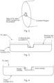
- Fig. 3 shows a representation of the possible locations of brazing discs (in an example, location 1 is chosen) with the "Polygon" type connection.
- the polygon of the step can have a "diameter” in terms of a circle around the apexes or vertices of a few mm, such as 3, 3.5, 4, 4.5, 5, 5.5 and the step can have a length or depth perpendicular to the diameter of less than 1mm, 1mm, or more than 1mm.
- the diameter of the circumscribed circle of the polygon and the step depth can be higher or lower based on material and design of contact piece and stem.
- the diameter of the polygon shaped step is slightly larger than the diameter of the hole in the contact piece into which it is to be pushed. This difference is the radial overlap.
- the polygon on the step deforms slightly due to the mechanical interference. This provides a very secure interference fit and holds the stem and the contact piece together ready for a final one step brazing process and also, holds the pieces together during the brazing process, without the need for other means to hold the parts together ready for and during brazing.
- the axial overlap relates to the difference between the length or depth of the step and the depth of the hole in the contact piece, and the length of the step can be made less than the depth of the hole taking into account tolerances, or the stem depth can be made to match the depth of the hole.
- all surfaces of the stem, the shoulders either side of the step, apexes or vertices of the step, and the bottom of the step can be in contact with the contact piece for the OSB process.
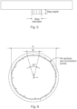
- a step having a polygon shape becomes more difficult to manufacture as the number of sides of the polygon increases, where step diameter and depth are shown for example in Fig. 5 , where the circumscribed circle of the polygon is governed by the step diameter (in an example, it is 2,8mm) of the stem.
- the size of the step and the size of the hole in the contact piece have to be taken into account as well as the strength of the mechanical connection required, taking into account the increased difficulty of manufacture with increasing sides of the polygon.
- the number of connection points between the contact piece and the stem increases (see Fig. 6 ). This along with sharp edges of the polygon ensures a strong mechanical connection between them.
- the polygon sides can be increased from 12 as shown in Fig. 6 to 15 as shown in Fig. 7 .
- the polygons described can be manufactured to achieve tight tolerances.
- a further advantage in addition to not requiring extra means to hold the pieces together for and in a final brazing step is that existing parts, contact pieces and stems, can be used with minor modifications and no additional tool is required for manufacturing the shapes over that used by manufacturing teams.
- the polygon shape can be optimized for all types of vacuum interrupters where smaller overlap lengths can be used reducing contact material thickness and also, material of the stem.
- the contact brazing disc is placed on the stem before mounting the contact.
- Fig. 8 shows an example of a stem and contact piece prior to being pressed together and after being pressed together.
Landscapes
- Engineering & Computer Science (AREA)
- Manufacturing & Machinery (AREA)
- Manufacture Of Switches (AREA)
Abstract
- a stem; and
- a contact piece;
wherein an end of the stem comprises a step or projection;
wherein a first side of the contact piece is configured to come into contact with another contact piece of a circuit breaker;
wherein a second side of the contact piece comprises a circular cross section hole;
wherein the step or projection of the stem is located within the circular cross section hole of the contact piece; and
wherein the step or projection of the stem has a polygon cross section.
Description
- The present invention relates to contact for a circuit breaker and a method of manufacturing a contact for a circuit breaker.
- Currently, for certain vacuum interrupters, an additional assembly brazing step is used for connecting a contact piece to a stem/carrier (both on the fixed contact side and the moving contact side) before a One Shot Brazing (OSB) process, in order that the contact piece does not fall off the stem during OSB. This additional brazing process takes place in a separate furnace with special brazing material for connecting only the contact piece to the stem. For other vacuum interrupters, different types of standard mechanical connections are used to hold the contact piece and stem together for OSB. The above issues apply to contacts for other types of circuit breaker.
- The additional fixation requirement prior to the final OSB process requires extra/special parts, takes time, and increases the cost of the contact (the contact finally brazed to the stem).
- There is a need to address these issues.
- Therefore, it would be advantageous to have an improved technique of fixing a stem to a contact piece for a resultant contact of a circuit breaker such as a vacuum interrupter.
- The object of the present invention is solved with the subject matter of the independent claims, wherein further embodiments are incorporated in the dependent claims.
- In an aspect, there is provided a contact for a circuit breaker, the contact comprising:
- a stem; and
- a contact piece.
- In this manner, by having a polygon cross section to the step or projection of the stem that is inserted into the contact piece of a contact for a circuit breaker, a better mechanical connection can be provided between the stem and the contact piece compared to a step or projection that has a circular cross section, because the step or projection can be designed in order that two or more apexes of the polygon towards opposite sides of the polygon are in contact with the inside of the hole of the contact piece at the same time. This means that additional support is not required to hold the stem and contact piece together for a subsequent brazing process. Thus, a one-shot-brazing process can be utilized to fix the stem to the contact piece without having to use for example a pre-brazing step or other pre-fixation step to hold the contact piece in place for a final brazing process that will provide for the final secure means by which the contact piece is fixed to the stem.
- In an example, the step or projection of the stem protrudes from shoulders of the end of the stem.
- In an example, at least a portion of the shoulders of the end of the stem are in contact with second surface of the contact piece around the circular cross section hole.
- In an example, the contact comprises a brazing disc. The brazing disc is located between the shoulders of the end of the stem and the second surface of the contact piece around the circular cross section hole.
- In an example, at least a portion of the shoulders of the end of the stem are in contact with the brazing disc.
- In an example, at least a portion of the second surface of the contact piece around the circular cross section hole is in contact with the brazing disc.
- In an example, the step or projection of the stem has a polygon cross section that is a 8 sided, 9 sided, 10 sided, 11 sided, 12 sided, 13 sided, 14 sided, 15 sided, 16 sided, 17 sided, 18 sided, 19 sided, or 20 sided.
- In an example, the step or projection of the stem has a polygon cross section that is a 4 sided, 5 sided, 6 sided, 7 sided, or more than 20 sided.
- In an example, before being inserted into the circular cross section hole of the contact piece, the step or projection had a polygon cross section with a largest width greater than a diameter of the circular cross section hole in the contact piece.
- In an example, a length of the step or projection of the stem perpendicular to the polygon cross section is equal to or less than a depth of the circular cross section hole in the contact piece.
- In an aspect, there is provided a method of manufacturing a contact for a circuit breaker, the method comprising:
- pushing a step or projection at an end of a stem into a circular cross section hole in a second side of a contact piece. A first side of the contact piece, when the contact has been manufactured, is configured to come into contact with another contact piece of a circuit breaker. Prior to being pushed into the circular cross section hole of the contact piece the step or projection of the stem has a polygon cross section.
- In this manner, by having a polygon cross section to the step or projection of the stem that is inserted into the contact piece of a contact for a circuit breaker a better mechanical connection can be provided between the stem and the contact piece compared to a step or projection that has a circular cross section, because the step or projection can be designed in order that two or more apexes of the polygon towards opposite sides of the polygon are in contact with the inside of the hole of the contact piece at the same time. This means that additional support is not required to hold the stem and contact piece together for a subsequent brazing process. Thus, a one-shot-brazing process can be utilized to fix the stem to the contact piece without having to use for example a pre-brazing step or other pre-fixation step to hold the contact piece in place for a final brazing process that will provide for the final secure means by which the contact piece is fixed to the stem. The polygon shaped step or projection can have apexes spaced apart that are matched to the diameter of the hole in the contact piece, and can have apexes spaced apart that are in effect greater than the diameter of the hole in the contact piece - in other words a circle around the polygon shaped step or projection that touches apexes and has no apex outside of the circle has a diameter greater than the diameter of the hole in the contact piece, and now the polygon shaped step or projection of the stem, made for example from copper, copper alloy, stainless steel or steel alloys, will deform slightly as it is pushed into the hole of the contact piece that can be made of a refractory metal or alloy, such as alloys of Cu, Cr, W, Carbide or Ag, thereby providing for a very secure fit.
- In an example, the step or projection of the stem protrudes from shoulders of the end of the stem.
- In an example, after the step or projection is pushed into the circular cross section hole of the contact piece at least a portion of the shoulders of the end of the stem are in contact with second surface of the contact piece around the circular cross section hole.
- In an example, the method comprises locating a brazing disc between the shoulders of the end of the stem and the second surface of the contact piece around the circular cross section hole.
- In an example, prior to being pushed into the circular cross section hole of the contact piece, the step or projection has a polygon cross section with a largest width greater than a diameter of the circular cross section hole in the contact piece.
- In an example, after the step or projection is pushed into the circular cross section hole of the contact piece the method comprises brazing the stem and the contact piece.
- The above aspects and examples will become apparent from and be elucidated with reference to the embodiments described hereinafter.
- Exemplary embodiments will be described in the following with reference to the following drawings:
-
Fig. 1 shows a sectional view of a vacuum interrupter with the new contacts; -
Fig. 2 shows an example of a stem with a 12-sided polygon step or projection; -
Fig. 3 shows a representation of the possible locations of brazing disc (preferred is Location 1). If needed then the dimensions of the step and contact groove can be optimized for having a brazing disc atlocation 2; -
Fig. 4 shows an example of a stem connected to a contact piece; -
Fig. 5 shows an example of a stem with a step or projection showing the diameter and depth of the step or projection; -
Fig. 6 shows an example of a 12 sided polygon shaped step or projection of a stem located within a hole of a contact piece where all apexes or vertices of the polygon are in contact with the inner wall of the hole; -
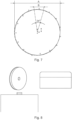
Fig. 7 shows an example of a 15 sided polygon shaped step or projection of a stem located within a hole of a contact piece where all apexes or vertices of the polygon are in contact with the inner wall of the hole; and -
Fig. 8 shows an example of a stem and contact piece shown prior to being pressed together and shown after being pressed together. -
Figs. 1-8 relate to the new contact. - An example of the contact comprises a stem, and a contact piece. An end of the stem comprises a step or projection. A first side of the contact piece is configured to come into contact with another contact piece of a circuit breaker. A second side of the contact piece comprises a circular cross section hole. The step or projection of the stem is located within the circular cross section hole of the contact piece. The step or projection of the stem has a polygon cross section.
- In this manner, by having a polygon cross section to the step or projection of the stem that is inserted into the contact piece of a contact for a circuit breaker a better mechanical connection can be provided between the stem and the contact piece compared to a step or projection that has a circular cross section, because the step or projection can be designed in order that two or more apexes of the polygon towards opposite sides of the polygon are in contact with the inside of the hole of the contact piece at the same time. This means that additional support is not required to hold the stem and contact piece together for a subsequent brazing process. Thus, a one-shot-brazing process can be utilized to fix the stem to the contact piece without having to use for example a pre-brazing step or other pre-fixation step to hold the contact piece in place for a final brazing process that will provide for the final secure means by which the contact piece is fixed to the stem.
- In an example, a material of the contact piece comprises alloys of Cu and W.
- In an example, a material of the stem comprises Cu.
- According to an example, the step or projection of the stem protrudes from shoulders of the end of the stem.
- According to an example, at least a portion of the shoulders of the end of the stem are in contact with second surface of the contact piece around the circular cross section hole.
- In an example, the shoulders of the end of the stem are in contact with second surface of the contact piece around the circular cross section hole.
- Thus, by designing the contact piece and stem with its step or projection appropriately, a flush fit between the stem and the contact piece is provided, where after the step or projection is pushed into a hole of the contact piece, the parts of the stem around the step or projection (its shoulders) can sit tightly against the surface of the contact piece around the hole, providing for a very robust final contact. In this case a brazing disc need not be utilized during a one shot brazing process.
- According to an example, the contact comprises a brazing disc. The brazing disc is located between the shoulders of the end of the stem and the second surface of the contact piece around the circular cross section hole.
- According to an example, at least a portion of the shoulders of the end of the stem are in contact with the brazing disc.
- Thus, by designing the contact piece and stem with its step or projection appropriately, a flush fit between the stem and the contact piece is provided, where after the step or projection is pushed into a hole of the contact piece, the parts of the stem around the step or projection (its shoulders) can sit tightly against the surface of the contact piece around the hole, providing for a very robust final contact.
- In an example, the shoulders of the end of the stem are in contact with the brazing disc.
- According to an example, at least a portion of the second surface of the contact piece around the circular cross section hole is in contact with the brazing disc.
- In an example, the second surface of the contact piece around the circular cross section hole is in contact with the brazing disc.
- In an example, a first surface of the brazing disc is in contact with the shoulders of the end of the stem and a second surface of the brazing disc is in contact with the second surface of the contact piece around the circular cross section hole.
- According to an example, the step or projection of the stem has a polygon cross section that is a 8 sided, 9 sided, 10 sided, 11 sided, 12 sided, 13 sided, 14 sided, 15 sided, 16 sided, 17 sided, 18 sided, 19 sided, or 20 sided.
- In an example, the step or projection of the stem has a polygon cross section that is a 4 sided, 5 sided, 6 sided, 7 sided, or more than 20 sided.
- According to an example, before being inserted into the circular cross section hole of the contact piece, the step or projection had a polygon cross section with a largest width greater than a diameter of the circular cross section hole in the contact piece.
- In an example, a circle that touches the apexes of the polygon cross section of the step or projection has a diameter greater than a diameter of the circular cross section hole in the contact piece.
- According to an example, a length of the step or projection of the stem perpendicular to the polygon cross section is equal to or less than a depth of the circular cross section hole in the contact piece.
- An example of a method of manufacturing a contact for a circuit breaker comprises:
- pushing a step or projection at an end of a stem into a circular cross section hole in a second side of a contact piece. A first side of the contact piece, when the contact has been manufactured, is configured to come into contact with another contact piece of a circuit breaker. Prior to being pushed into the circular cross section hole of the contact piece the step or projection of the stem has a polygon cross section.
- In this manner, by having a polygon cross section to the step or projection of the stem that is inserted into the contact piece of a contact for a circuit breaker a better mechanical connection can be provided between the stem and the contact piece compared to a step or projection that has a circular cross section, because the step or projection can be designed in order that two or more apexes of the polygon towards opposite sides of the polygon are in contact with the inside of the hole of the contact piece at the same time. This means that additional support is not required to hold the stem and contact piece together for a subsequent brazing process. Thus, a one-shot-brazing process can be utilized to fix the stem to the contact piece without having to use for example a pre-brazing step or other pre-fixation step to hold the contact piece in place for a final brazing process that will provide for the final secure means by which the contact piece is fixed to the stem.
- In an example, a material of the contact piece comprises alloy of Wand Cu.
- In an example, a material of the stem comprises Cu.
- According to an example, the step or projection of the stem protrudes from shoulders of the end of the stem.
- According to an example, after the step or projection is pushed into the circular cross section hole of the contact piece at least a portion of the shoulders of the end of the stem are in contact with second surface of the contact piece around the circular cross section hole.
- In an example, the shoulders of the end of the stem are in contact with second surface of the contact piece around the circular cross section hole.
- According to an example, the method comprises locating a brazing disc between the shoulders of the end of the stem and the second surface of the contact piece around the circular cross section hole.
- In an example, at least a portion of the shoulders of the end of the stem are in contact with the brazing disc.
- In an example, the shoulders of the end of the stem are in contact with the brazing disc.
- In an example, at least a portion of the second surface of the contact piece around the circular cross section hole is in contact with the brazing disc.
- In an example, the second surface of the contact piece around the circular cross section hole is in contact with the brazing disc.
- In an example, a first surface of the brazing disc is in contact with the shoulders of the end of the stem and a second surface of the brazing disc is in contact with the second surface of the contact piece around the circular cross section hole.
- In an example, prior to being pushed into the circular cross section hole of the contact piece the step or projection of the stem has a polygon cross section that is a 8 sided, 9 sided, 10 sided, 11 sided, 12 sided, 13 sided, 14 sided, 15 sided, 16 sided, 17 sided, 18 sided, 19 sided, or 20 sided.
- In an example, prior to being pushed into the circular cross section hole of the contact piece the step or projection of the stem has a polygon cross section that is a 4 sided, 5 sided, 6 sided, 7 sided, or more than 20 sided.
- According to an example, prior to being pushed into the circular cross section hole of the contact piece, the step or projection has a polygon cross section with a largest width greater than a diameter of the circular cross section hole in the contact piece.
- In an example, a length of the step or projection of the stem perpendicular to the polygon cross section is equal to or less than a depth of the circular cross section hole in the contact piece.
- According to an example, after the step or projection is pushed into the circular cross section hole of the contact piece the method comprises brazing the stem and the contact piece.
- In an example, the method comprises brazing the stem and the contact piece in an oven.
- The new contact and how it is manufactured is now described in specific detail with respect to several embodiments, where reference is again made to
Figs. 1-8 . - As described above, the new technique of connecting a contact piece to a stem provides a contact that avoid use of an additional assembly brazing step to keep the stem and contact piece together for a final OSB process. This significantly reduces the cost. Further, it helps in the reduction of contact material thickness due to a considerably smaller overlap length needed both in axial and radial directions and also, to a reduction of stem material due to a lower diameter of the connection step or projection of the stem. This is a major advantage over standard mechanical connections and further, avoids the need of a special brazing material as used in certain cases. Overall, it not only leads to huge cost savings, but also plays a major role in decreasing the carbon footprint. This new technique of forming the new contact, connecting the pieces ready for final brazing, and the resultant contact can be for a fixed contact of a vacuum interrupter and for a moving contact of a vacuum interrupter without any issue of overflow of the braze material. The new technique and the resultant contact is independent of brazing material and can be extended to all vacuum interrupters, where in certain situations the polygon shape (equal sides or unequal sides) of the step or projection can be optimized based on the specific contact design and material.
- A vacuum interrupter, as shown in
Fig. 1 , where the connection between the stem and the contact piece uses a "Polygon" type connection (as shown inFig. 2 ) that in this example with a 12-sided polygon (in an example, equal sides) on the step of the stem on which the contact is pressed. -
Fig. 3 shows a representation of the possible locations of brazing discs (in an example,location 1 is chosen) with the "Polygon" type connection. For example, the polygon of the step can have a "diameter" in terms of a circle around the apexes or vertices of a few mm, such as 3, 3.5, 4, 4.5, 5, 5.5 and the step can have a length or depth perpendicular to the diameter of less than 1mm, 1mm, or more than 1mm. The diameter of the circumscribed circle of the polygon and the step depth can be higher or lower based on material and design of contact piece and stem. - With the new design, a much smaller overlap length both in axial and radial directions (see
Fig. 4 ) is needed as compared to the existing connection design used in other vacuum interrupters. Thus, the diameter of the polygon shaped step is slightly larger than the diameter of the hole in the contact piece into which it is to be pushed. This difference is the radial overlap. As the step is pushed into the hole, the polygon on the step deforms slightly due to the mechanical interference. This provides a very secure interference fit and holds the stem and the contact piece together ready for a final one step brazing process and also, holds the pieces together during the brazing process, without the need for other means to hold the parts together ready for and during brazing. The axial overlap relates to the difference between the length or depth of the step and the depth of the hole in the contact piece, and the length of the step can be made less than the depth of the hole taking into account tolerances, or the stem depth can be made to match the depth of the hole. Thus, all surfaces of the stem, the shoulders either side of the step, apexes or vertices of the step, and the bottom of the step can be in contact with the contact piece for the OSB process. - For a specific vacuum interrupter use case, several polygon shapes were checked before finalizing on an optimum 12-sided polygon. For other use cases, different polygon shapes can be optimum, for example a 15-sided polygon as shown in
Fig. 7 . In general, a step having a polygon shape becomes more difficult to manufacture as the number of sides of the polygon increases, where step diameter and depth are shown for example inFig. 5 , where the circumscribed circle of the polygon is governed by the step diameter (in an example, it is 2,8mm) of the stem. Thus, in designing a polygon shape for the step of the stem, the size of the step and the size of the hole in the contact piece have to be taken into account as well as the strength of the mechanical connection required, taking into account the increased difficulty of manufacture with increasing sides of the polygon. To explain further, for a given overlap length, as the number of polygon sides increases, the number of connection points between the contact piece and the stem increases (seeFig. 6 ). This along with sharp edges of the polygon ensures a strong mechanical connection between them. Thus, if required the polygon sides can be increased from 12 as shown inFig. 6 to 15 as shown inFig. 7 . - The polygons described can be manufactured to achieve tight tolerances. A further advantage in addition to not requiring extra means to hold the pieces together for and in a final brazing step is that existing parts, contact pieces and stems, can be used with minor modifications and no additional tool is required for manufacturing the shapes over that used by manufacturing teams.
- Based on the contact material and weight of the contact, the polygon shape can be optimized for all types of vacuum interrupters where smaller overlap lengths can be used reducing contact material thickness and also, material of the stem.
- The contact brazing disc is placed on the stem before mounting the contact.
-
Fig. 8 shows an example of a stem and contact piece prior to being pressed together and after being pressed together.
Claims (15)
- A contact for a circuit breaker, the contact comprising:- a stem; and- a contact piece;wherein an end of the stem comprises a step or projection;wherein a first side of the contact piece is configured to come into contact with another contact piece of a circuit breaker;wherein a second side of the contact piece comprises a circular cross section hole;wherein the step or projection of the stem is located within the circular cross section hole of the contact piece; andwherein the step or projection of the stem has a polygon cross section.
- Contact according to claim 1, wherein the step or projection of the stem protrudes from shoulders of the end of the stem.
- Contact according to claim 2, wherein at least a portion of the shoulders of the end of the stem are in contact with second surface of the contact piece around the circular cross section hole.
- Contact according to claim 2, wherein the contact comprises a brazing disc, wherein the brazing disc is located between the shoulders of the end of the stem and the second surface of the contact piece around the circular cross section hole.
- Contact according to claim 4, wherein at least a portion of the shoulders of the end of the stem are in contact with the brazing disc.
- Contact according to any of claims 4-5, wherein at least a portion of the second surface of the contact piece around the circular cross section hole is in contact with the brazing disc.
- Contact according to any of claims 1-6, wherein the step or projection of the stem has a polygon cross section or deformed polygon cross section that is a 8 sided, 9 sided, 10 sided, 11 sided, 12 sided, 13 sided, 14 sided, 15 sided, 16 sided, 17 sided, 18 sided, 19 sided, or 20 sided.
- Contact according to any of claims 1-7, wherein before being inserted into the circular cross section hole of the contact piece, the step or projection had a polygon cross section with a largest width greater than a diameter of the circular cross section hole in the contact piece.
- Contact according to any of claims 1-8, wherein a length of the step or projection of the stem perpendicular to the polygon cross section is equal to or less than a depth of the circular cross section hole in the contact piece.
- A method of manufacturing a contact for a circuit breaker, the method comprising:- pushing a step or projection at an end of a stem into a circular cross section hole in a second side of a contact piece, wherein a first side of the contact piece is configured to come into contact with another contact piece of a circuit breaker, and wherein prior to being pushed into the circular cross section hole of the contact piece the step or projection of the stem has a polygon cross section.
- Method according to claim 10, wherein the step or projection of the stem protrudes from shoulders of the end of the stem.
- Method according to claim 11, wherein after the step or projection is pushed into the circular cross section hole of the contact piece at least a portion of the shoulders of the end of the stem are in contact with second surface of the contact piece around the circular cross section hole.
- Method according to claim 11, wherein the method comprises locating a brazing disc between the shoulders of the end of the stem and the second surface of the contact piece around the circular cross section hole.
- Method according to any of claims 10-13, wherein prior to being pushed into the circular cross section hole of the contact piece, the step or projection has a polygon cross section with a largest width greater than a diameter of the circular cross section hole in the contact piece.
- Method according to any of claims 10-13, wherein after the step or projection is pushed into the circular cross section hole of the contact piece the method comprises brazing the stem and the contact piece.
Priority Applications (2)
| Application Number | Priority Date | Filing Date | Title |
|---|---|---|---|
| EP22207447.8A EP4372777A1 (en) | 2022-11-15 | 2022-11-15 | Contact for a circuit breaker |
| CN202311516431.9A CN118053698A (en) | 2022-11-15 | 2023-11-15 | Contact for circuit breaker |
Applications Claiming Priority (1)
| Application Number | Priority Date | Filing Date | Title |
|---|---|---|---|
| EP22207447.8A EP4372777A1 (en) | 2022-11-15 | 2022-11-15 | Contact for a circuit breaker |
Publications (1)
| Publication Number | Publication Date |
|---|---|
| EP4372777A1 true EP4372777A1 (en) | 2024-05-22 |
Family
ID=84358068
Family Applications (1)
| Application Number | Title | Priority Date | Filing Date |
|---|---|---|---|
| EP22207447.8A Pending EP4372777A1 (en) | 2022-11-15 | 2022-11-15 | Contact for a circuit breaker |
Country Status (2)
| Country | Link |
|---|---|
| EP (1) | EP4372777A1 (en) |
| CN (1) | CN118053698A (en) |
Citations (3)
| Publication number | Priority date | Publication date | Assignee | Title |
|---|---|---|---|---|
| JPS5875721A (en) * | 1981-10-30 | 1983-05-07 | 株式会社東芝 | Vacuum valve |
| JPH09190744A (en) * | 1996-01-10 | 1997-07-22 | Mitsubishi Electric Corp | Vacuum circuit breaker and manufacturing method thereof |
| JPH09274836A (en) * | 1996-04-05 | 1997-10-21 | Mitsubishi Electric Corp | Vacuum valve and electrode manufacturing method thereof |
-
2022
- 2022-11-15 EP EP22207447.8A patent/EP4372777A1/en active Pending
-
2023
- 2023-11-15 CN CN202311516431.9A patent/CN118053698A/en active Pending
Patent Citations (3)
| Publication number | Priority date | Publication date | Assignee | Title |
|---|---|---|---|---|
| JPS5875721A (en) * | 1981-10-30 | 1983-05-07 | 株式会社東芝 | Vacuum valve |
| JPH09190744A (en) * | 1996-01-10 | 1997-07-22 | Mitsubishi Electric Corp | Vacuum circuit breaker and manufacturing method thereof |
| JPH09274836A (en) * | 1996-04-05 | 1997-10-21 | Mitsubishi Electric Corp | Vacuum valve and electrode manufacturing method thereof |
Also Published As
| Publication number | Publication date |
|---|---|
| CN118053698A (en) | 2024-05-17 |
Similar Documents
| Publication | Publication Date | Title |
|---|---|---|
| KR101018980B1 (en) | Electrical contacts | |
| US4746301A (en) | S-shaped compliant pin | |
| CN101682137A (en) | Contactor | |
| US5743769A (en) | Press-in contact and a method for manufacturing the same | |
| JPS6245654B2 (en) | ||
| US12413004B2 (en) | Piston assembly and spring-loaded contact | |
| EP4372777A1 (en) | Contact for a circuit breaker | |
| US6177647B1 (en) | Electrode for plasma arc torch and method of fabrication | |
| EP1300603A2 (en) | Balance weight for wheel of a two-wheel vehicle | |
| EP0026117A1 (en) | Electrical contact for an electrical connector and method of making same | |
| JPS59131781A (en) | Enclosed type motor-compressor | |
| JP2519642B2 (en) | Airtight connector manufacturing method | |
| US20050042935A1 (en) | Solderless electrical contact | |
| CA2471358C (en) | Solder ring for production of vacuum tube and method for the production of such a solder ring; and of a vacuum tube | |
| JP2009081018A (en) | Magnetron, manufacturing device of magnetron, and manufacturing method of magnetron | |
| US4712293A (en) | Method for securing a slow-wave structure in enveloping structure with crimped spacers | |
| JP2005076741A (en) | Piping joint structure and manufacturing method thereof | |
| JP3729521B2 (en) | Lightning arrestor | |
| EP0609838A2 (en) | Helical Slow-Wave Circuit Assembly | |
| EP0086532B1 (en) | Electric component with upset connection wires | |
| US7044810B2 (en) | Electrical wedge connector | |
| JP2010135102A (en) | Vacuum valve | |
| US4196309A (en) | Semiconductor device subassembly and manufacture thereof | |
| JP4158240B2 (en) | Fixing the rivet type contact to the base metal | |
| JPH0313709B2 (en) |
Legal Events
| Date | Code | Title | Description |
|---|---|---|---|
| PUAI | Public reference made under article 153(3) epc to a published international application that has entered the european phase |
Free format text: ORIGINAL CODE: 0009012 |
|
| STAA | Information on the status of an ep patent application or granted ep patent |
Free format text: STATUS: THE APPLICATION HAS BEEN PUBLISHED |
|
| AK | Designated contracting states |
Kind code of ref document: A1 Designated state(s): AL AT BE BG CH CY CZ DE DK EE ES FI FR GB GR HR HU IE IS IT LI LT LU LV MC ME MK MT NL NO PL PT RO RS SE SI SK SM TR |
|
| STAA | Information on the status of an ep patent application or granted ep patent |
Free format text: STATUS: REQUEST FOR EXAMINATION WAS MADE |
|
| 17P | Request for examination filed |
Effective date: 20241016 |
|
| RBV | Designated contracting states (corrected) |
Designated state(s): AL AT BE BG CH CY CZ DE DK EE ES FI FR GB GR HR HU IE IS IT LI LT LU LV MC ME MK MT NL NO PL PT RO RS SE SI SK SM TR |
|
| GRAP | Despatch of communication of intention to grant a patent |
Free format text: ORIGINAL CODE: EPIDOSNIGR1 |
|
| STAA | Information on the status of an ep patent application or granted ep patent |
Free format text: STATUS: GRANT OF PATENT IS INTENDED |
|
| INTG | Intention to grant announced |
Effective date: 20260227 |
|
| GRAS | Grant fee paid |
Free format text: ORIGINAL CODE: EPIDOSNIGR3 |
|
| GRAA | (expected) grant |
Free format text: ORIGINAL CODE: 0009210 |
|
| STAA | Information on the status of an ep patent application or granted ep patent |
Free format text: STATUS: THE PATENT HAS BEEN GRANTED |