EP4372712A1 - Detecting airflow and temperature conditions of a fire sensing device - Google Patents
Detecting airflow and temperature conditions of a fire sensing device Download PDFInfo
- Publication number
- EP4372712A1 EP4372712A1 EP23205183.9A EP23205183A EP4372712A1 EP 4372712 A1 EP4372712 A1 EP 4372712A1 EP 23205183 A EP23205183 A EP 23205183A EP 4372712 A1 EP4372712 A1 EP 4372712A1
- Authority
- EP
- European Patent Office
- Prior art keywords
- airflow
- sensing device
- fire sensing
- fire
- measurement
- Prior art date
- Legal status (The legal status is an assumption and is not a legal conclusion. Google has not performed a legal analysis and makes no representation as to the accuracy of the status listed.)
- Pending
Links
Images




Classifications
-
- G—PHYSICS
- G08—SIGNALLING
- G08B—SIGNALLING SYSTEMS, e.g. PERSONAL CALLING SYSTEMS; ORDER TELEGRAPHS; ALARM SYSTEMS
- G08B29/00—Checking or monitoring of signalling or alarm systems; Prevention or correction of operating errors, e.g. preventing unauthorised operation
- G08B29/02—Monitoring continuously signalling or alarm systems
- G08B29/04—Monitoring of the detection circuits
- G08B29/043—Monitoring of the detection circuits of fire detection circuits
-
- G—PHYSICS
- G08—SIGNALLING
- G08B—SIGNALLING SYSTEMS, e.g. PERSONAL CALLING SYSTEMS; ORDER TELEGRAPHS; ALARM SYSTEMS
- G08B17/00—Fire alarms; Alarms responsive to explosion
- G08B17/10—Actuation by presence of smoke or gases, e.g. automatic alarm devices for analysing flowing fluid materials by the use of optical means
-
- F—MECHANICAL ENGINEERING; LIGHTING; HEATING; WEAPONS; BLASTING
- F24—HEATING; RANGES; VENTILATING
- F24F—AIR-CONDITIONING; AIR-HUMIDIFICATION; VENTILATION; USE OF AIR CURRENTS FOR SCREENING
- F24F11/00—Control or safety arrangements
- F24F11/30—Control or safety arrangements for purposes related to the operation of the system, e.g. for safety or monitoring
- F24F11/32—Responding to malfunctions or emergencies
- F24F11/33—Responding to malfunctions or emergencies to fire, excessive heat or smoke
-
- F—MECHANICAL ENGINEERING; LIGHTING; HEATING; WEAPONS; BLASTING
- F24—HEATING; RANGES; VENTILATING
- F24F—AIR-CONDITIONING; AIR-HUMIDIFICATION; VENTILATION; USE OF AIR CURRENTS FOR SCREENING
- F24F11/00—Control or safety arrangements
- F24F11/30—Control or safety arrangements for purposes related to the operation of the system, e.g. for safety or monitoring
- F24F11/49—Control or safety arrangements for purposes related to the operation of the system, e.g. for safety or monitoring ensuring correct operation, e.g. by trial operation or configuration checks
-
- G—PHYSICS
- G08—SIGNALLING
- G08B—SIGNALLING SYSTEMS, e.g. PERSONAL CALLING SYSTEMS; ORDER TELEGRAPHS; ALARM SYSTEMS
- G08B17/00—Fire alarms; Alarms responsive to explosion
- G08B17/06—Electric actuation of the alarm, e.g. using a thermally-operated switch
-
- G—PHYSICS
- G08—SIGNALLING
- G08B—SIGNALLING SYSTEMS, e.g. PERSONAL CALLING SYSTEMS; ORDER TELEGRAPHS; ALARM SYSTEMS
- G08B29/00—Checking or monitoring of signalling or alarm systems; Prevention or correction of operating errors, e.g. preventing unauthorised operation
- G08B29/18—Prevention or correction of operating errors
- G08B29/20—Calibration, including self-calibrating arrangements
- G08B29/22—Provisions facilitating manual calibration, e.g. input or output provisions for testing; Holding of intermittent values to permit measurement
-
- H—ELECTRICITY
- H04—ELECTRIC COMMUNICATION TECHNIQUE
- H04L—TRANSMISSION OF DIGITAL INFORMATION, e.g. TELEGRAPHIC COMMUNICATION
- H04L67/00—Network arrangements or protocols for supporting network services or applications
- H04L67/01—Protocols
- H04L67/12—Protocols specially adapted for proprietary or special-purpose networking environments, e.g. medical networks, sensor networks, networks in vehicles or remote metering networks
-
- F—MECHANICAL ENGINEERING; LIGHTING; HEATING; WEAPONS; BLASTING
- F24—HEATING; RANGES; VENTILATING
- F24F—AIR-CONDITIONING; AIR-HUMIDIFICATION; VENTILATION; USE OF AIR CURRENTS FOR SCREENING
- F24F2110/00—Control inputs relating to air properties
- F24F2110/10—Temperature
-
- F—MECHANICAL ENGINEERING; LIGHTING; HEATING; WEAPONS; BLASTING
- F24—HEATING; RANGES; VENTILATING
- F24F—AIR-CONDITIONING; AIR-HUMIDIFICATION; VENTILATION; USE OF AIR CURRENTS FOR SCREENING
- F24F2110/00—Control inputs relating to air properties
- F24F2110/30—Velocity
-
- F—MECHANICAL ENGINEERING; LIGHTING; HEATING; WEAPONS; BLASTING
- F24—HEATING; RANGES; VENTILATING
- F24F—AIR-CONDITIONING; AIR-HUMIDIFICATION; VENTILATION; USE OF AIR CURRENTS FOR SCREENING
- F24F2110/00—Control inputs relating to air properties
- F24F2110/50—Air quality properties
- F24F2110/64—Airborne particle content
-
- F—MECHANICAL ENGINEERING; LIGHTING; HEATING; WEAPONS; BLASTING
- F24—HEATING; RANGES; VENTILATING
- F24F—AIR-CONDITIONING; AIR-HUMIDIFICATION; VENTILATION; USE OF AIR CURRENTS FOR SCREENING
- F24F2110/00—Control inputs relating to air properties
- F24F2110/50—Air quality properties
- F24F2110/65—Concentration of specific substances or contaminants
- F24F2110/72—Carbon monoxide
Definitions
- the present disclosure relates generally to devices, methods, and systems for detecting airflow and temperature conditions of a fire sensing device.
- a fire alarm system may include a fire control panel and a plurality of fire sensing devices (e.g., smoke detectors), located throughout the building (e.g., on different floors and/or in different rooms of the building) that can sense a fire occurring in the building (e.g., by detecting smoke) and provide a notification of the fire to the occupants of the building via alarms.
- a fire sensing devices e.g., smoke detectors
- smoke can be diverted from entering a fire sensing device and/or diluted before entering the fire sensing device.
- smoke can be diverted and/or diluted due to an external airflow, an open window, an open door, a fan, an air conditioner, and/or a heating, ventilation, and air conditioning (HVAC) system.
- HVAC heating, ventilation, and air conditioning
- One fire sensing device includes an airflow sensor and a controller configured to receive a measurement from the airflow sensor, compare the measurement to a baseline range, and transmit a message responsive to the measurement being outside of the baseline range.
- a fire sensing device in accordance with the present disclosure can detect airflow and/or temperature conditions of the fire sensing device to determine whether the device is in danger of delaying or missing detection of smoke fire, and/or carbon monoxide.
- the fire sensing device can utilize an airflow sensor, an air movement device, a particle counter, a pressure sensor, and/or a temperature sensor to determine the airflow and/or temperature to which the fire sensing device is being exposed to determine whether the device is in danger of delaying or missing detection of the smoke, fire, and/or carbon monoxide.
- fire sensing devices in accordance with the present disclosure may transmit a message, increase their sensitivity to heat, smoke, or carbon monoxide, transmit a command to an HVAC system, determine maintenance and/or relocation is unnecessary, and/or determine maintenance and/or relocation is needed without manual inspection by a person, which can reduce the chance of the fire sensing device delaying or missing the detection of smoke, fire, and/or carbon monoxide.
- a can refer to one or more such things, while “a plurality of” something can refer to more than one such things.
- a number of components can refer to one or more components, while “a plurality of components” can refer to more than one component.
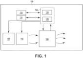
- FIG. 1 illustrates a block diagram of a fire sensing device 100 in accordance with an embodiment of the present disclosure.
- the fire sensing device 100 includes a controller (e.g., microcontroller) 122, a particle counter 104, and an air movement device 116.
- controller e.g., microcontroller
- the controller 122 can include a memory 124 and a processor 126.
- Memory 124 can be any type of storage medium that can be accessed by processor 126 to perform various examples of the present disclosure.
- memory 124 can be a non-transitory computer readable medium having computer readable instructions (e.g., computer program instructions) stored thereon that are executable by processor 126 to detect airflow and temperature conditions of fire sensing device 100 in accordance with the present disclosure.
- processor 126 can execute the executable instructions stored in memory 124 to receive a measurement from an airflow sensor, a particle counter 104, or a temperature sensor of fire sensing device 100, compare the measurement to a baseline range, and transmit (e.g., via a network, as will be further described herein) a message and/or command responsive to the measurement being outside of the baseline range.
- the message and/or command can be transmitted to, for example, a fire control panel, a monitoring device, or a cloud computing device.
- the air movement device 116 can be a fan and can rotate in response to the fire sensing device 100 being exposed to a threshold airflow.
- the controller 122 can detect airflow within the fire sensing device 100 responsive to detecting the rotation of the air movement device 116.
- Controller 112 can determine maintenance and/or relocation of the fire sensing device 100 is needed responsive to detecting the airflow and transmit a message responsive to determining maintenance and/or relocation of the fire sensing device 100 is needed.
- controller 112 can increase the sensitivity level of fire sensing device 100 to heat, smoke, or carbon monoxide responsive to detecting the airflow.
- an airflow sensor 118 can be used to detect airflow instead of or in combination with the air movement device 116.
- the controller 122 can receive a measurement (e.g., an airflow measurement) from the airflow sensor 118 in response to the airflow sensor 118 detecting airflow.
- the airflow sensor 118 can be the air movement device 116, an airflow detector, a volume airflow sensor, a mass airflow sensor, or a pressure sensor.
- a temperature sensor 119 can be included in the fire sensing device 100.
- the temperature sensor 119 can detect a temperature measurement in or around the fire sensing device 100.
- the temperature sensor 119 can be a thermistor.
- the controller 122 can receive the measurement (e.g., the temperature measurement) from the temperature sensor 119.
- the controller 122 can compare the measurement received from the airflow sensor 118 and/or the temperature sensor 119 to a baseline range (e.g., to determine whether the measurement is within the baseline range) and transmit a message responsive to the measurement being outside of the baseline range.
- controller 112 can compare the airflow measurement to a baseline airflow and transmit the message if the airflow measurement exceeds the baseline airflow.
- controller 112 can compare the temperature measurement to a baseline temperature range and transmit the message if the temperature measurement is outside the baseline temperature range.
- controller 112 can increase the sensitivity of the fire sensing device 100 to heat, smoke, or carbon monoxide responsive to the measurement being outside of the baseline range.
- the fire sensing device 100 can further include a particle generator 117 to generate particles.
- the controller 122 can cause the particle generator 117 to generate particles and can receive a measurement from the particle counter 104 after causing the particle generator 117 to generate the particles.
- the particle counter 104 can be an optical scatter chamber that can measure a quantity of particles therein.
- the controller 122 can compare the measurement received from the particle counter 104 to a baseline particle range (e.g., to determine whether the quantity of particles is outside the baseline particle range) and can transmit a message responsive to the measurement received from the particle counter 104 being outside the baseline particle range.
- the memory 124 can store the baseline range of particles, airflow, and/or temperature, a measured quantity of particles, airflow, and/or temperature, and/or a different measured quantity of particles, airflow, and/or temperature.
- controller 122 can receive the baseline range and store the received baseline range in the memory 124.
- the measured quantity can be stored in memory 124 as a baseline quantity of particles, airflow, and/or temperature if, for example, the measured quantity of particles, airflow, or temperature is the first (e.g., initial) quantity of particles, airflow, or temperature measured by the fire sensing device 100. Controller 122 can then determine the baseline range to which subsequent measurements are compared based on this initial measurement. As an additional example, a subsequently measured airflow can be compared to the baseline airflow.
- FIG 2 illustrates a portion of an example of a fire sensing device 200 in accordance with an embodiment of the present disclosure.
- the fire sensing device 200 can correspond to the fire sensing device 100 of Figure 1 and can be, but is not limited to, a fire and/or smoke detector of a fire control system such as, for instance, self-test detector.
- a fire sensing device 200 can sense a fire occurring in a facility and trigger a fire response to provide a notification of the fire to occupants of the facility.
- a fire response can include visual and/or audio alarms, for example.
- a fire response can also notify emergency services (e.g., fire departments, police departments, etc.)
- a plurality of fire sensing devices can be located throughout a facility (e.g., on different floors and/or in different rooms of the facility).
- fire sensing device 200 can include a particle counter 204 illustrated as an optical scatter chamber and an air movement device 216, which can correspond to the particle counter 104 and the air movement device 116 of Figure 1 , respectively.
- the air movement device 216 is illustrated as a fan in Figure 2 , any device capable of sensing airflow can be used.
- an airflow detector, a volume airflow sensor, a mass airflow sensor, or a pressure sensor could be used instead of and/or in combination with a fan as the air movement device 216.
- the air movement device 216 can also control the airflow through the fire sensing device 200, including the optical scatter chamber.
- the air movement device 216 can move particles, gases, and/or aerosol from a first end of the fire sensing device 200 to a second end of the fire sensing device 200.
- the air movement device 216 can start responsive to a command and can stop responsive to a command and/or after a particular period of time.
- a fire sensing device 200 can automatically, or upon receipt of a command, detect particles.
- the particle counter 204 can measure a quantity of particles in the optical scatter chamber.
- the fire sensing device 200 can compare the measured quantity of particles to a baseline range and transmit a message responsive to the measurement being outside the baseline range.
- FIG. 3 illustrates a block diagram of a fire alarm system 320 in accordance with an embodiment of the present disclosure.
- the fire alarm system 320 can include a fire sensing device 300, a fire control panel 301, and a computing device 303.
- Fire sensing device 300 can be, for example, fire sensing device 100 and/or 200 previously described in connection with Figures 1 and 2 , respectively.
- fire alarm system 320 can include a plurality of fire sensing devices analogous to fire sensing device 300.
- the fire control panel 301 can be a monitoring device, a fire detection control system, and/or a cloud computing device of the fire alarm system 320.
- the fire control panel 301 can be configured to send commands to and/or receive messages from a fire sensing device 300 via a wired or wireless network (not shown in Figure 3 for simplicity and so as not to obscure embodiments of the present disclosure).
- the fire sensing device 300 can transmit a message to the fire control panel 301 responsive to a measurement by the fire sensing device 300 being outside a baseline range, as previously described herein. Such a message can, for example, direct a technician to move the fire sensing device 300.
- the fire control panel 301 can receive messages from, a number of fire sensing devices analogous to fire sensing device 300.
- the fire control panel 301 can receive messages from each of a number of fire sensing devices analogous to fire sensing device 300 and store data based on the messages from each of the number of fire sensing devices.
- the fire control panel 301 can include a user interface 336.
- the user interface 336 can be a graphical user interface (GUI) that can provide and/or receive information to and/or from a user and/or the fire sensing device 300.
- GUI graphical user interface
- the user interface 336 can display messages and/or data received from the fire sensing device 300.
- the user interface 336 can display a message indicating fire sensing device 300 needs maintenance and/or relocation, direct a technician to move the fire sensing device 300, direct a technician to increase a sensitivity of the fire sensing device 300 to heat, smoke, and/or carbon monoxide, and/or transmit a command to an HVAC system.
- the networks described herein can be a network relationship through which fire sensing device 300 and/or fire control panel 301 can communicate with each other.
- Examples of such a network relationship can include a distributed computing environment (e.g., a cloud computing environment), a wide area network (WAN) such as the Internet, a local area network (LAN), a personal area network (PAN), a campus area network (CAN), or metropolitan area network (MAN), among other types of network relationships.
- the network can include a number of servers that receive information from and transmit information to fire sensing device 300 and/or fire control panel 301 via a wired or wireless network.
- a "network” can provide a communication system that directly or indirectly links two or more computers and/or peripheral devices and allows a fire control panel 301 to access data and/or resources on a fire sensing device 300 and vice versa.
- a network can allow users to share resources on their own systems with other network users and to access information on centrally located systems or on systems that are located at remote locations.
- a network can tie a number of computing devices together to form a distributed control network (e.g., cloud).
- a network may provide connections to the Internet and/or to the networks of other entities (e.g., organizations, institutions, etc.). Users may interact with network-enabled software applications to make a network request, such as to get data. Applications may also communicate with network management software, which can interact with network hardware to transmit information between devices on the network.
- entities e.g., organizations, institutions, etc.
- network management software can interact with network hardware to transmit information between devices on the network.
- the network can be used by the fire sensing device 300 and/or the fire control panel 301 to communicate with a computing device 303.
- the computing device 303 can be a personal laptop computer, a desktop computer, a mobile device such as a smart phone, a tablet, a wrist-worn device, and/or redundant combinations thereof, among other types of computing devices.
- the computing device 303 can receive messages from a number of fire sensing devices analogous to fire sensing device 300 and/or a number of fire control panels analogous to fire control panel 301 and transmit commands based on the messages to one or more of the number of fire sensing devices and/or one or more of the number of fire control panels.
- the fire sensing device 300 can transmit a message that maintenance and/or relocation of the fire sensing device 300 is needed to the computing device 303 responsive to a measurement from an airflow sensor being outside of a baseline range, a measurement from a particle counter being outside a baseline range, detecting airflow within the fire sensing device 300, and/or a measurement from a temperature sensor being outside of a baseline range.
- the computing device 303 can include a user interface 337.
- the user interface 337 can be a GUI that can provide and/or receive information to and/or from a user, the fire sensing device 300 and/or the fire control panel 301.
- the user interface 337 can display messages and/or data received from the fire sensing device 300 and/or the fire control panel 301.
- the user interface 337 can display a fire sensing device 300 needing maintenance and/or relocation, direct a technician to move the fire sensing device 300, direct a technician to increase a sensitivity of the fire sensing device 300 to heat, smoke, and/or carbon monoxide, and/or transmit a command to an HVAC system.
- Figure 4 illustrates a method flow diagram 439 of an airflow detection function of a fire sensing device in accordance with an embodiment of the present disclosure.
- the method illustrated in Figure 4 can be performed by the fire sensing device previously described in connection with Figures 1 , 2 , and/or 3.
- airflow enters the fire sensing device, and it is determined whether the airflow disturbs an air movement device (e.g., air movement device 116 and 216 of Figures 1 and 2 , respectively) of the fire sensing device at block 442.
- the air movement device can be a fan, and the disturbance of the air movement device can be a rotation of the fan.
- the air movement device can rotate in response to any airflow entering the fire sensing device, or responsive to a threshold amount of airflow entering the fire sensing device.
- the fan may be of a certain size, weight, and/or form such that only a threshold amount of airflow may cause it to rotate.
- the method can end at block 444.
- the airflow detection process can end at block 444 if rotation of the air movement device is not detected.
- the fire sensing device can transmit a message at block 446.
- the fire sensing device can transmit the message at 446 if rotation of the air movement device is detected.
- Airflow can be detected within the fire sensing device responsive to detecting the rotation of the air movement device. In some examples, the airflow can be determined based on revolutions per minute of the air movement device.
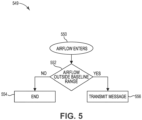
- Figure 5 illustrates a method flow diagram 549 of an airflow detection function of a fire sensing device (e.g., fire sensing device 100, 200, and 300 of Figures 1 , 2 , and 3 , respectively) in accordance with an embodiment of the present disclosure.
- a fire sensing device e.g., fire sensing device 100, 200, and 300 of Figures 1 , 2 , and 3 , respectively.
- airflow can enter the fire sensing device, and it is determined whether the airflow is outside a baseline range at block 552.
- an airflow sensor e.g., airflow sensor 118 of Figure 1
- the airflow sensor can be included in or coupled to the fire sensing device.
- the airflow sensor can be an airflow detector, volume airflow sensor, a mass airflow sensor, or a pressure sensor.
- the airflow sensor can measure airflow inside or just outside of the fire sensing device and transmit the measurement to a controller (e.g., controller 122 of Figure 1 ) of the fire sensing device.
- the controller can compare the measurement to a baseline range.
- the baseline range can be or be based on a previous measurement received at the controller from the airflow sensor, another fire sensing device, a fire control panel, a monitoring device, and/or a cloud computing device.
- the controller can store the baseline range in memory (e.g., memory 124 in Figure 1 ).
- the method can end at block 554. If the airflow is outside the baseline range, the fire sensing device can transmit a message at block 556. The message can be transmitted to another fire sensing device, a fire control panel, a monitoring device, and/or a cloud computing device.
- the controller can determine the fire sensing device needs maintenance and/or relocation, increase a sensitivity of the fire sensing device to heat, smoke, or carbon monoxide, and/or transmit a command to an HVAC system responsive to the measurement being outside of the baseline range, detecting airflow, and/or the airflow exceeding a baseline airflow.
- airflow can be detected in an additional fire sensing device.
- the additional fire sensing device can determine whether maintenance and/or relocation is necessary or unnecessary responsive to the airflow in an analogous manner.
- the airflow measurement of the fire sensing device and the additional fire sensing device can be used to determine a direction of airflow within the fire sensing device.
- the direction of the airflow can be included in the transmitted message.
- Figure 6 illustrates a method flow diagram 659 of a temperature detection function of a fire sensing device (e.g., fire sensing device 100, 200, and 300 of Figures 1 , 2 , and 3 , respectively) in accordance with an embodiment of the present disclosure.
- a fire sensing device e.g., fire sensing device 100, 200, and 300 of Figures 1 , 2 , and 3 , respectively.
- airflow can enter the fire sensing device, and it is determined whether the temperature of the air is outside a baseline range at block 662.
- the temperature can be measured by a temperature sensor, for example, a thermistor.
- the baseline range can be received at and/or stored by the fire sensing device.
- the method can end at block 664. If the temperature is outside the baseline range, the fire sensing device can transmit a message at block 666.
- the message can be transmitted to a fire control panel, a monitoring device, or a cloud computing device, for example. In a number of embodiments, the message can direct a technician to move the fire sensing device.
- Figure 7 illustrates a method flow diagram 769 of a particle detection function of a fire sensing device (e.g., fire sensing device 100, 200, and 300 in Figures 1 , 2 , and 3 , respectively) in accordance with an embodiment of the present disclosure.
- a fire sensing device e.g., fire sensing device 100, 200, and 300 in Figures 1 , 2 , and 3 , respectively.
- airflow can enter the fire sensing device, and it is determined whether a quantity of particles in the fire sensing device is outside a baseline range at block 772.
- the quantity of particles can be measured by a particle counter (e.g., particle counter 104 and 204 of Figures 1 and 2 , respectively.
- a particle generator e.g., particle generator 117 of Figure 1
- the method can end at block 774. If the quantity of particles is outside the baseline range, the fire sensing device can transmit a message at 776.
- the message can be transmitted to a fire control panel, a monitoring device, or a cloud computing device, for example. In a number of embodiments, the message can direct a technician to move the fire sensing device.
Landscapes
- Engineering & Computer Science (AREA)
- Chemical & Material Sciences (AREA)
- Combustion & Propulsion (AREA)
- Mechanical Engineering (AREA)
- General Engineering & Computer Science (AREA)
- General Physics & Mathematics (AREA)
- Physics & Mathematics (AREA)
- Emergency Management (AREA)
- Business, Economics & Management (AREA)
- Computer Security & Cryptography (AREA)
- Medical Informatics (AREA)
- Computer Networks & Wireless Communication (AREA)
- Signal Processing (AREA)
- General Health & Medical Sciences (AREA)
- Computing Systems (AREA)
- Health & Medical Sciences (AREA)
- Analytical Chemistry (AREA)
- Fire-Detection Mechanisms (AREA)
- Fire Alarms (AREA)
Abstract
Devices, methods, and systems for detecting airflow and temperature conditions of a fire sensing device are described herein. Airflow in a fire device can divert and dilute smoke or gas, resulting in a missed detection. A fire device includes an airflow sensor and a controller configured to receive a measurement from the airflow sensor, compare the measurement to a baseline range, and transmit a message responsive to the measurement being outside of the baseline range.
Description
- The present disclosure relates generally to devices, methods, and systems for detecting airflow and temperature conditions of a fire sensing device.
- Large facilities, such as commercial buildings, office buildings, hospitals, and the like, as well as residential buildings, such as apartments, townhomes, single family homes, and the like may have a fire alarm system that can be triggered during an emergency situation (e.g., a fire) to warn occupants to evacuate. For example, a fire alarm system may include a fire control panel and a plurality of fire sensing devices (e.g., smoke detectors), located throughout the building (e.g., on different floors and/or in different rooms of the building) that can sense a fire occurring in the building (e.g., by detecting smoke) and provide a notification of the fire to the occupants of the building via alarms.
- In some cases, however, smoke can be diverted from entering a fire sensing device and/or diluted before entering the fire sensing device. For example, smoke can be diverted and/or diluted due to an external airflow, an open window, an open door, a fan, an air conditioner, and/or a heating, ventilation, and air conditioning (HVAC) system. As such, the detection of smoke, fire, and/or carbon monoxide by the fire sensing device can be delayed or missed, allowing smoke, fire, and/or carbon monoxide to accumulate and/or spread, which could result in loss of life and/or property.
-
-
Figure 1 illustrates a block diagram of a fire sensing device in accordance with an embodiment of the present disclosure. -
Figure 2 illustrates a portion of an example of a fire sensing device in accordance with an embodiment of the present disclosure. -
Figure 3 illustrates a block diagram of a fire alarm system in accordance with an embodiment of the present disclosure. -
Figure 4 illustrates a method flow diagram of an airflow detection function of a fire sensing device in accordance with an embodiment of the present disclosure. -
Figure 5 illustrates a method flow diagram of an airflow detection function of a fire sensing device in accordance with an embodiment of the present disclosure. -
Figure 6 illustrates a method flow diagram of a temperature detection function of a fire sensing device in accordance with an embodiment of the present disclosure. -
Figure 7 illustrates a method flow diagram of a particle detection function of a fire sensing device in accordance with an embodiment of the present disclosure. - Devices, methods, and systems for detecting airflow and temperature conditions of a fire sensing device are described herein. One fire sensing device includes an airflow sensor and a controller configured to receive a measurement from the airflow sensor, compare the measurement to a baseline range, and transmit a message responsive to the measurement being outside of the baseline range.
- In contrast to previous fire sensing devices in which a person (e.g., maintenance engineer and/or operator) would have to manually inspect whether a fire sensing device was being exposed to an external airflow from an open window or an open door and/or too close to a fan, an air conditioner, and/or an inlet or an outlet of an HVAC system to determine if the device is in danger of delaying or missing detection of smoke, fire, and/or carbon monoxide, a fire sensing device in accordance with the present disclosure can detect airflow and/or temperature conditions of the fire sensing device to determine whether the device is in danger of delaying or missing detection of smoke fire, and/or carbon monoxide. For example, the fire sensing device can utilize an airflow sensor, an air movement device, a particle counter, a pressure sensor, and/or a temperature sensor to determine the airflow and/or temperature to which the fire sensing device is being exposed to determine whether the device is in danger of delaying or missing detection of the smoke, fire, and/or carbon monoxide. Accordingly, fire sensing devices in accordance with the present disclosure may transmit a message, increase their sensitivity to heat, smoke, or carbon monoxide, transmit a command to an HVAC system, determine maintenance and/or relocation is unnecessary, and/or determine maintenance and/or relocation is needed without manual inspection by a person, which can reduce the chance of the fire sensing device delaying or missing the detection of smoke, fire, and/or carbon monoxide.
- In the following detailed description, reference is made to the accompanying drawings that form a part hereof. The drawings show by way of illustration how one or more embodiments of the disclosure may be practiced. These embodiments are described in sufficient detail to enable those of ordinary skill in the art to practice one or more embodiments of this disclosure. It is to be understood that other embodiments may be utilized and that mechanical, electrical, and/or process changes may be made without departing from the scope of the present disclosure.
- As will be appreciated, elements shown in the various embodiments herein can be added, exchanged, combined, and/or eliminated so as to provide a number of additional embodiments of the present disclosure. The proportion and the relative scale of the elements provided in the figures are intended to illustrate the embodiments of the present disclosure and should not be taken in a limiting sense.
- The figures herein follow a numbering convention in which the first digit or digits correspond to the drawing figure number and the remaining digits identify an element or component in the drawing. Similar elements or components between different figures may be identified by the use of similar digits. For example, 104 may reference element "04" in
Figure 1 , and a similar element may be referenced as 204 inFigure 2 . - As used herein, "a", "an", or "a number of" something can refer to one or more such things, while "a plurality of" something can refer to more than one such things. For example, "a number of components" can refer to one or more components, while "a plurality of components" can refer to more than one component.
-
Figure 1 illustrates a block diagram of afire sensing device 100 in accordance with an embodiment of the present disclosure. Thefire sensing device 100 includes a controller (e.g., microcontroller) 122, aparticle counter 104, and anair movement device 116. - The
controller 122 can include amemory 124 and aprocessor 126.Memory 124 can be any type of storage medium that can be accessed byprocessor 126 to perform various examples of the present disclosure. For example,memory 124 can be a non-transitory computer readable medium having computer readable instructions (e.g., computer program instructions) stored thereon that are executable byprocessor 126 to detect airflow and temperature conditions offire sensing device 100 in accordance with the present disclosure. For instance,processor 126 can execute the executable instructions stored inmemory 124 to receive a measurement from an airflow sensor, aparticle counter 104, or a temperature sensor offire sensing device 100, compare the measurement to a baseline range, and transmit (e.g., via a network, as will be further described herein) a message and/or command responsive to the measurement being outside of the baseline range. The message and/or command can be transmitted to, for example, a fire control panel, a monitoring device, or a cloud computing device. - The
air movement device 116 can be a fan and can rotate in response to thefire sensing device 100 being exposed to a threshold airflow. Thecontroller 122 can detect airflow within thefire sensing device 100 responsive to detecting the rotation of theair movement device 116. Controller 112 can determine maintenance and/or relocation of thefire sensing device 100 is needed responsive to detecting the airflow and transmit a message responsive to determining maintenance and/or relocation of thefire sensing device 100 is needed. In some embodiments, controller 112 can increase the sensitivity level offire sensing device 100 to heat, smoke, or carbon monoxide responsive to detecting the airflow. - In a number of embodiments, an
airflow sensor 118 can be used to detect airflow instead of or in combination with theair movement device 116. Thecontroller 122 can receive a measurement (e.g., an airflow measurement) from theairflow sensor 118 in response to theairflow sensor 118 detecting airflow. In some examples, theairflow sensor 118 can be theair movement device 116, an airflow detector, a volume airflow sensor, a mass airflow sensor, or a pressure sensor. - A
temperature sensor 119 can be included in thefire sensing device 100. Thetemperature sensor 119 can detect a temperature measurement in or around thefire sensing device 100. In a number of embodiments, thetemperature sensor 119 can be a thermistor. Thecontroller 122 can receive the measurement (e.g., the temperature measurement) from thetemperature sensor 119. - In some examples, the
controller 122 can compare the measurement received from theairflow sensor 118 and/or thetemperature sensor 119 to a baseline range (e.g., to determine whether the measurement is within the baseline range) and transmit a message responsive to the measurement being outside of the baseline range. For example, controller 112 can compare the airflow measurement to a baseline airflow and transmit the message if the airflow measurement exceeds the baseline airflow. As an additional example, controller 112 can compare the temperature measurement to a baseline temperature range and transmit the message if the temperature measurement is outside the baseline temperature range. In some embodiments, controller 112 can increase the sensitivity of thefire sensing device 100 to heat, smoke, or carbon monoxide responsive to the measurement being outside of the baseline range. - The
fire sensing device 100 can further include aparticle generator 117 to generate particles. Thecontroller 122 can cause theparticle generator 117 to generate particles and can receive a measurement from theparticle counter 104 after causing theparticle generator 117 to generate the particles. In some examples, theparticle counter 104 can be an optical scatter chamber that can measure a quantity of particles therein. Thecontroller 122 can compare the measurement received from theparticle counter 104 to a baseline particle range (e.g., to determine whether the quantity of particles is outside the baseline particle range) and can transmit a message responsive to the measurement received from theparticle counter 104 being outside the baseline particle range. - The
memory 124 can store the baseline range of particles, airflow, and/or temperature, a measured quantity of particles, airflow, and/or temperature, and/or a different measured quantity of particles, airflow, and/or temperature. In some examples,controller 122 can receive the baseline range and store the received baseline range in thememory 124. In some examples, the measured quantity can be stored inmemory 124 as a baseline quantity of particles, airflow, and/or temperature if, for example, the measured quantity of particles, airflow, or temperature is the first (e.g., initial) quantity of particles, airflow, or temperature measured by thefire sensing device 100.Controller 122 can then determine the baseline range to which subsequent measurements are compared based on this initial measurement. As an additional example, a subsequently measured airflow can be compared to the baseline airflow. -
Figure 2 illustrates a portion of an example of afire sensing device 200 in accordance with an embodiment of the present disclosure. Thefire sensing device 200 can correspond to thefire sensing device 100 ofFigure 1 and can be, but is not limited to, a fire and/or smoke detector of a fire control system such as, for instance, self-test detector. - A
fire sensing device 200 can sense a fire occurring in a facility and trigger a fire response to provide a notification of the fire to occupants of the facility. A fire response can include visual and/or audio alarms, for example. A fire response can also notify emergency services (e.g., fire departments, police departments, etc.) In some examples, a plurality of fire sensing devices can be located throughout a facility (e.g., on different floors and/or in different rooms of the facility). - As shown in
Figure 2 ,fire sensing device 200 can include aparticle counter 204 illustrated as an optical scatter chamber and anair movement device 216, which can correspond to theparticle counter 104 and theair movement device 116 ofFigure 1 , respectively. Although theair movement device 216 is illustrated as a fan inFigure 2 , any device capable of sensing airflow can be used. For example, an airflow detector, a volume airflow sensor, a mass airflow sensor, or a pressure sensor could be used instead of and/or in combination with a fan as theair movement device 216. - The
air movement device 216 can also control the airflow through thefire sensing device 200, including the optical scatter chamber. For example, theair movement device 216 can move particles, gases, and/or aerosol from a first end of thefire sensing device 200 to a second end of thefire sensing device 200. Theair movement device 216 can start responsive to a command and can stop responsive to a command and/or after a particular period of time. - A
fire sensing device 200 can automatically, or upon receipt of a command, detect particles. Theparticle counter 204 can measure a quantity of particles in the optical scatter chamber. Thefire sensing device 200 can compare the measured quantity of particles to a baseline range and transmit a message responsive to the measurement being outside the baseline range. -
Figure 3 illustrates a block diagram of afire alarm system 320 in accordance with an embodiment of the present disclosure. Thefire alarm system 320 can include afire sensing device 300, afire control panel 301, and acomputing device 303.Fire sensing device 300 can be, for example,fire sensing device 100 and/or 200 previously described in connection withFigures 1 and2 , respectively. Further, although a singlefire sensing device 300 is illustrated inFigure 3 for simplicity and so as not to obscure embodiments of the present disclosure,fire alarm system 320 can include a plurality of fire sensing devices analogous to firesensing device 300. - The
fire control panel 301 can be a monitoring device, a fire detection control system, and/or a cloud computing device of thefire alarm system 320. Thefire control panel 301 can be configured to send commands to and/or receive messages from afire sensing device 300 via a wired or wireless network (not shown inFigure 3 for simplicity and so as not to obscure embodiments of the present disclosure). For example, thefire sensing device 300 can transmit a message to thefire control panel 301 responsive to a measurement by thefire sensing device 300 being outside a baseline range, as previously described herein. Such a message can, for example, direct a technician to move thefire sensing device 300. Thefire control panel 301 can receive messages from, a number of fire sensing devices analogous to firesensing device 300. For example, thefire control panel 301 can receive messages from each of a number of fire sensing devices analogous to firesensing device 300 and store data based on the messages from each of the number of fire sensing devices. - In a number of embodiments, the
fire control panel 301 can include auser interface 336. Theuser interface 336 can be a graphical user interface (GUI) that can provide and/or receive information to and/or from a user and/or thefire sensing device 300. Theuser interface 336 can display messages and/or data received from thefire sensing device 300. For example, theuser interface 336 can display a message indicatingfire sensing device 300 needs maintenance and/or relocation, direct a technician to move thefire sensing device 300, direct a technician to increase a sensitivity of thefire sensing device 300 to heat, smoke, and/or carbon monoxide, and/or transmit a command to an HVAC system. - The networks described herein can be a network relationship through which
fire sensing device 300 and/orfire control panel 301 can communicate with each other. Examples of such a network relationship can include a distributed computing environment (e.g., a cloud computing environment), a wide area network (WAN) such as the Internet, a local area network (LAN), a personal area network (PAN), a campus area network (CAN), or metropolitan area network (MAN), among other types of network relationships. For instance, the network can include a number of servers that receive information from and transmit information to firesensing device 300 and/orfire control panel 301 via a wired or wireless network. - As used herein, a "network" can provide a communication system that directly or indirectly links two or more computers and/or peripheral devices and allows a
fire control panel 301 to access data and/or resources on afire sensing device 300 and vice versa. A network can allow users to share resources on their own systems with other network users and to access information on centrally located systems or on systems that are located at remote locations. For example, a network can tie a number of computing devices together to form a distributed control network (e.g., cloud). - A network may provide connections to the Internet and/or to the networks of other entities (e.g., organizations, institutions, etc.). Users may interact with network-enabled software applications to make a network request, such as to get data. Applications may also communicate with network management software, which can interact with network hardware to transmit information between devices on the network.
- In some examples, the network can be used by the
fire sensing device 300 and/or thefire control panel 301 to communicate with acomputing device 303. Thecomputing device 303 can be a personal laptop computer, a desktop computer, a mobile device such as a smart phone, a tablet, a wrist-worn device, and/or redundant combinations thereof, among other types of computing devices. Thecomputing device 303 can receive messages from a number of fire sensing devices analogous to firesensing device 300 and/or a number of fire control panels analogous tofire control panel 301 and transmit commands based on the messages to one or more of the number of fire sensing devices and/or one or more of the number of fire control panels. For example, thefire sensing device 300 can transmit a message that maintenance and/or relocation of thefire sensing device 300 is needed to thecomputing device 303 responsive to a measurement from an airflow sensor being outside of a baseline range, a measurement from a particle counter being outside a baseline range, detecting airflow within thefire sensing device 300, and/or a measurement from a temperature sensor being outside of a baseline range. - In a number of embodiments, the
computing device 303 can include auser interface 337. Theuser interface 337 can be a GUI that can provide and/or receive information to and/or from a user, thefire sensing device 300 and/or thefire control panel 301. Theuser interface 337 can display messages and/or data received from thefire sensing device 300 and/or thefire control panel 301. For example, theuser interface 337 can display afire sensing device 300 needing maintenance and/or relocation, direct a technician to move thefire sensing device 300, direct a technician to increase a sensitivity of thefire sensing device 300 to heat, smoke, and/or carbon monoxide, and/or transmit a command to an HVAC system. -
Figure 4 illustrates a method flow diagram 439 of an airflow detection function of a fire sensing device in accordance with an embodiment of the present disclosure. In some embodiments, the method illustrated inFigure 4 can be performed by the fire sensing device previously described in connection withFigures 1 ,2 , and/or 3. - At
block 440, airflow enters the fire sensing device, and it is determined whether the airflow disturbs an air movement device (e.g.,air movement device Figures 1 and2 , respectively) of the fire sensing device atblock 442. In some examples, the air movement device can be a fan, and the disturbance of the air movement device can be a rotation of the fan. The air movement device can rotate in response to any airflow entering the fire sensing device, or responsive to a threshold amount of airflow entering the fire sensing device. For example, the fan may be of a certain size, weight, and/or form such that only a threshold amount of airflow may cause it to rotate. - If the air movement device is not disturbed, the method can end at
block 444. For example, the airflow detection process can end atblock 444 if rotation of the air movement device is not detected. If the air movement device is disturbed, the fire sensing device can transmit a message atblock 446. For example, the fire sensing device can transmit the message at 446 if rotation of the air movement device is detected. Airflow can be detected within the fire sensing device responsive to detecting the rotation of the air movement device. In some examples, the airflow can be determined based on revolutions per minute of the air movement device. -
Figure 5 illustrates a method flow diagram 549 of an airflow detection function of a fire sensing device (e.g.,fire sensing device Figures 1 ,2 , and3 , respectively) in accordance with an embodiment of the present disclosure. - At
block 550, airflow can enter the fire sensing device, and it is determined whether the airflow is outside a baseline range atblock 552. For instance, an airflow sensor (e.g.,airflow sensor 118 ofFigure 1 ) can be included in or coupled to the fire sensing device. In some examples, the airflow sensor can be an airflow detector, volume airflow sensor, a mass airflow sensor, or a pressure sensor. The airflow sensor can measure airflow inside or just outside of the fire sensing device and transmit the measurement to a controller (e.g.,controller 122 ofFigure 1 ) of the fire sensing device. - The controller can compare the measurement to a baseline range. The baseline range can be or be based on a previous measurement received at the controller from the airflow sensor, another fire sensing device, a fire control panel, a monitoring device, and/or a cloud computing device. The controller can store the baseline range in memory (e.g.,
memory 124 inFigure 1 ). - If the airflow is not outside of the baseline range, the method can end at
block 554. If the airflow is outside the baseline range, the fire sensing device can transmit a message atblock 556. The message can be transmitted to another fire sensing device, a fire control panel, a monitoring device, and/or a cloud computing device. In a number of embodiments, the controller can determine the fire sensing device needs maintenance and/or relocation, increase a sensitivity of the fire sensing device to heat, smoke, or carbon monoxide, and/or transmit a command to an HVAC system responsive to the measurement being outside of the baseline range, detecting airflow, and/or the airflow exceeding a baseline airflow. - In a number of embodiments, airflow can be detected in an additional fire sensing device. The additional fire sensing device can determine whether maintenance and/or relocation is necessary or unnecessary responsive to the airflow in an analogous manner. The airflow measurement of the fire sensing device and the additional fire sensing device can be used to determine a direction of airflow within the fire sensing device. The direction of the airflow can be included in the transmitted message.
-
Figure 6 illustrates a method flow diagram 659 of a temperature detection function of a fire sensing device (e.g.,fire sensing device Figures 1 ,2 , and3 , respectively) in accordance with an embodiment of the present disclosure. - At
block 660, airflow can enter the fire sensing device, and it is determined whether the temperature of the air is outside a baseline range atblock 662. The temperature can be measured by a temperature sensor, for example, a thermistor. In a number of embodiments, the baseline range can be received at and/or stored by the fire sensing device. - If the temperature is not outside the baseline range, the method can end at
block 664. If the temperature is outside the baseline range, the fire sensing device can transmit a message atblock 666. The message can be transmitted to a fire control panel, a monitoring device, or a cloud computing device, for example. In a number of embodiments, the message can direct a technician to move the fire sensing device. -
Figure 7 illustrates a method flow diagram 769 of a particle detection function of a fire sensing device (e.g.,fire sensing device Figures 1 ,2 , and3 , respectively) in accordance with an embodiment of the present disclosure. - At
block 770, airflow can enter the fire sensing device, and it is determined whether a quantity of particles in the fire sensing device is outside a baseline range atblock 772. The quantity of particles can be measured by a particle counter (e.g.,particle counter Figures 1 and2 , respectively. In some examples, a particle generator (e.g.,particle generator 117 ofFigure 1 ) can generate the particles prior to measuring the quantity of particles at the particle counter. - If the quantity of particles is not outside the baseline range, the method can end at
block 774. If the quantity of particles is outside the baseline range, the fire sensing device can transmit a message at 776. The message can be transmitted to a fire control panel, a monitoring device, or a cloud computing device, for example. In a number of embodiments, the message can direct a technician to move the fire sensing device. - Although specific embodiments have been illustrated and described herein, those of ordinary skill in the art will appreciate that any arrangement calculated to achieve the same techniques can be substituted for the specific embodiments shown. This disclosure is intended to cover any and all adaptations or variations of various embodiments of the disclosure.
- It is to be understood that the above description has been made in an illustrative fashion, and not a restrictive one. Combination of the above embodiments, and other embodiments not specifically described herein will be apparent to those of skill in the art upon reviewing the above description.
- The scope of the various embodiments of the disclosure includes any other applications in which the above structures and methods are used. Therefore, the scope of various embodiments of the disclosure should be determined with reference to the appended claims, along with the full range of equivalents to which such claims are entitled.
- In the foregoing Detailed Description, various features are grouped together in example embodiments illustrated in the figures for the purpose of streamlining the disclosure. This method of disclosure is not to be interpreted as reflecting an intention that the embodiments of the disclosure require more features than are expressly recited in each claim.
- Rather, as the following claims reflect, inventive subject matter lies in less than all features of a single disclosed embodiment. Thus, the following claims are hereby incorporated into the Detailed Description, with each claim standing on its own as a separate embodiment.
Claims (15)
- A fire sensing device (100, 200, 300), comprising:an airflow sensor (118); anda controller (122), configured to:receive a measurement from the airflow sensor (118);compare the measurement to a baseline range; andtransmit a message responsive to the measurement being outside of the baseline range.
- The device of claim 1, wherein the controller (122) is configured to increase a sensitivity of the fire sensing device (100, 200, 300) to heat, smoke, or carbon monoxide responsive to the measurement being outside of the baseline range.
- The device of claim 1, wherein the airflow sensor (118) is an air movement device (116, 216) or an airflow detector.
- The device of claim 1, further comprising a particle generator (117) and a particle counter (104, 204).
- The device of claim 4, wherein the controller (122) is configured to:cause the particle generator (117) to generate particles;receive a measurement from the particle counter (104, 204) after causing the particle generator (117) to generate the particles;compare the measurement received from the particle counter (104, 204) to an additional baseline range; andtransmit the message responsive to the measurement received from the particle counter (104, 204) being outside the additional baseline range.
- The device of claim 1, wherein the controller (122) is configured to receive a previous measurement from the airflow sensor (118), wherein the baseline range is based on the previous measurement.
- The device of claim 1, wherein the controller (122) is configured to transmit a command to a heating, ventilation, and air conditioning (HVAC) system responsive to the measurement being outside of the baseline range.
- A method of operating a fire sensing device (100, 200, 300), comprising:detecting airflow within the fire sensing device (100, 200, 300);determining maintenance or relocation of the fire sensing device (100, 200, 300) is needed responsive to detecting the airflow; andtransmitting a message responsive to determining maintenance or relocation of the fire sensing device (100, 200, 300) is needed.
- The method of claim 8, further comprising:detecting rotation of an air movement device (116, 216); anddetecting the airflow within the fire sensing device (100, 200, 300) responsive to detecting the rotation of the air movement device (116, 216).
- The method of claim 8, wherein the method includes detecting the airflow via a volume airflow sensor, a mass airflow sensor, or a pressure sensor.
- The method of claim 8, further comprising increasing a sensitivity level of the fire sensing device (100, 200, 300) to heat, smoke, or carbon monoxide responsive to detecting the airflow.
- The method of claim 8, further comprising:detecting a baseline airflow within the fire sensing device (100, 200, 300) prior to detecting the airflow;comparing the airflow to the baseline airflow; anddetermining the maintenance or relocation is needed responsive to the airflow exceeding the baseline airflow.
- The method of claim 8, further comprising:detecting airflow within an additional fire sensing device; anddetermining maintenance or relocation of the additional fire sensing device is not needed responsive to detecting the airflow within the additional fire sensing device.
- The method of claim 13, further comprising determining a direction of airflow within the fire sensing device (100, 200, 300) based on the detected airflow within the fire sensing device (100, 200, 300) and the detected airflow within the additional fire sensing device.
- The method of claim 14, wherein the message includes the direction of the airflow.
Applications Claiming Priority (1)
| Application Number | Priority Date | Filing Date | Title |
|---|---|---|---|
| US17/988,121 US12516838B2 (en) | 2022-11-16 | 2022-11-16 | Detecting airflow and temperature conditions of a fire sensing device |
Publications (1)
| Publication Number | Publication Date |
|---|---|
| EP4372712A1 true EP4372712A1 (en) | 2024-05-22 |
Family
ID=88511248
Family Applications (1)
| Application Number | Title | Priority Date | Filing Date |
|---|---|---|---|
| EP23205183.9A Pending EP4372712A1 (en) | 2022-11-16 | 2023-10-23 | Detecting airflow and temperature conditions of a fire sensing device |
Country Status (3)
| Country | Link |
|---|---|
| US (1) | US12516838B2 (en) |
| EP (1) | EP4372712A1 (en) |
| CN (1) | CN118053253A (en) |
Citations (5)
| Publication number | Priority date | Publication date | Assignee | Title |
|---|---|---|---|---|
| EP0365047A2 (en) * | 1983-10-21 | 1990-04-25 | IEI PTY Ltd. | Optical air pollution or smoke detection apparatus |
| WO2008016394A2 (en) * | 2006-07-28 | 2008-02-07 | Lawrence Kates | System and method for high-sensitivity sensor |
| US20160363470A1 (en) * | 2015-06-09 | 2016-12-15 | Sunonwealth Electric Machine Industry Co., Ltd. | Airflow Sensor and Airflow Detecting Module |
| EP3792890A1 (en) * | 2019-08-27 | 2021-03-17 | Honeywell International Inc. | Self-testing fire sensing device |
| EP3945510A1 (en) * | 2020-07-30 | 2022-02-02 | Carrier Corporation | Smoke detector with integrated sensing |
Family Cites Families (14)
| Publication number | Priority date | Publication date | Assignee | Title |
|---|---|---|---|---|
| AUPP199998A0 (en) | 1998-02-24 | 1998-03-19 | F F Seeley Nominees Pty Ltd | Improved fire detection |
| JP3739084B2 (en) | 2001-09-28 | 2006-01-25 | ホーチキ株式会社 | Fire heat detector |
| US7804402B2 (en) | 2007-01-26 | 2010-09-28 | Honeywell International Inc. | Fire detectors with environmental data input |
| US10527313B2 (en) * | 2012-11-15 | 2020-01-07 | NJK Precision LLC | Building airflow measuring system and method |
| US9058731B2 (en) | 2013-10-07 | 2015-06-16 | Tyco Fire & Security Gmbh | Smoke detector with airflow barrier |
| US9472079B2 (en) * | 2014-10-12 | 2016-10-18 | The Boeing Company | Method and system to enable selective smoke detection sensitivity |
| CN107969143B (en) * | 2015-07-28 | 2021-05-11 | 三菱电机株式会社 | Judgment support device, judgment support method, and recording medium |
| US10127800B2 (en) * | 2016-03-08 | 2018-11-13 | True Analytics, LLC | Method for sensor maintenance of redundant sensor loops |
| US11113828B2 (en) * | 2016-07-22 | 2021-09-07 | Google Llc | Determining sensor installation characteristics from camera image |
| CN110751817B (en) | 2019-10-23 | 2021-10-08 | 应急管理部沈阳消防研究所 | Test device and test method for response performance of fire detector in low temperature environment |
| US11024154B1 (en) | 2020-01-28 | 2021-06-01 | Honeywell International Inc. | Self-testing fire sensing device |
| US12235004B2 (en) * | 2020-07-30 | 2025-02-25 | The George Washington University | Sensor network for validation of healthy buildings and transportation systems |
| US11676466B2 (en) | 2020-08-19 | 2023-06-13 | Honeywell International Inc. | Self-calibrating fire sensing device |
| US11725991B1 (en) * | 2022-03-07 | 2023-08-15 | Beta Air, Llc | Systems and methods for determining a confidence level of a sensor measurement by a sensor of an electric aircraft |
-
2022
- 2022-11-16 US US17/988,121 patent/US12516838B2/en active Active
-
2023
- 2023-10-23 EP EP23205183.9A patent/EP4372712A1/en active Pending
- 2023-11-08 CN CN202311477907.2A patent/CN118053253A/en active Pending
Patent Citations (5)
| Publication number | Priority date | Publication date | Assignee | Title |
|---|---|---|---|---|
| EP0365047A2 (en) * | 1983-10-21 | 1990-04-25 | IEI PTY Ltd. | Optical air pollution or smoke detection apparatus |
| WO2008016394A2 (en) * | 2006-07-28 | 2008-02-07 | Lawrence Kates | System and method for high-sensitivity sensor |
| US20160363470A1 (en) * | 2015-06-09 | 2016-12-15 | Sunonwealth Electric Machine Industry Co., Ltd. | Airflow Sensor and Airflow Detecting Module |
| EP3792890A1 (en) * | 2019-08-27 | 2021-03-17 | Honeywell International Inc. | Self-testing fire sensing device |
| EP3945510A1 (en) * | 2020-07-30 | 2022-02-02 | Carrier Corporation | Smoke detector with integrated sensing |
Also Published As
| Publication number | Publication date |
|---|---|
| US20240159410A1 (en) | 2024-05-16 |
| CN118053253A (en) | 2024-05-17 |
| US12516838B2 (en) | 2026-01-06 |
Similar Documents
| Publication | Publication Date | Title |
|---|---|---|
| US12198532B2 (en) | Self-testing fire sensing device | |
| US11749097B2 (en) | Self-testing fire sensing device | |
| US12293651B2 (en) | Self-testing fire sensing device for confirming a fire | |
| CN103439954B (en) | A kind of warehouse environment control intelligent system | |
| US12516838B2 (en) | Detecting airflow and temperature conditions of a fire sensing device | |
| EP4310810A1 (en) | Performing a self-clean of a fire sensing device | |
| EP4231265A1 (en) | Testing a heat detector of a self-testing hazard sensing device | |
| US12597337B2 (en) | Event sensing device | |
| CN119067246A (en) | Generate event device optimization analysis in event system | |
| US12283175B2 (en) | Monitoring an aerosol density level in a fire sensing device | |
| EP4734090A1 (en) | Event monitoring and detection device testing | |
| EP4738303A2 (en) | Event detection device testing |
Legal Events
| Date | Code | Title | Description |
|---|---|---|---|
| PUAI | Public reference made under article 153(3) epc to a published international application that has entered the european phase |
Free format text: ORIGINAL CODE: 0009012 |
|
| STAA | Information on the status of an ep patent application or granted ep patent |
Free format text: STATUS: REQUEST FOR EXAMINATION WAS MADE |
|
| 17P | Request for examination filed |
Effective date: 20231023 |
|
| AK | Designated contracting states |
Kind code of ref document: A1 Designated state(s): AL AT BE BG CH CY CZ DE DK EE ES FI FR GB GR HR HU IE IS IT LI LT LU LV MC ME MK MT NL NO PL PT RO RS SE SI SK SM TR |
|
| STAA | Information on the status of an ep patent application or granted ep patent |
Free format text: STATUS: EXAMINATION IS IN PROGRESS |
|
| 17Q | First examination report despatched |
Effective date: 20251211 |