EP4372474A1 - Printing equipment for metallic material and printing method using same - Google Patents
Printing equipment for metallic material and printing method using same Download PDFInfo
- Publication number
- EP4372474A1 EP4372474A1 EP22842406.5A EP22842406A EP4372474A1 EP 4372474 A1 EP4372474 A1 EP 4372474A1 EP 22842406 A EP22842406 A EP 22842406A EP 4372474 A1 EP4372474 A1 EP 4372474A1
- Authority
- EP
- European Patent Office
- Prior art keywords
- toner
- photosensitive drum
- transfer belt
- metallic material
- unit
- Prior art date
- Legal status (The legal status is an assumption and is not a legal conclusion. Google has not performed a legal analysis and makes no representation as to the accuracy of the status listed.)
- Pending
Links
- 239000007769 metal material Substances 0.000 title claims abstract description 124
- 238000007639 printing Methods 0.000 title claims abstract description 96
- 238000000034 method Methods 0.000 title claims abstract description 50
- 238000007599 discharging Methods 0.000 claims description 18
- LFQSCWFLJHTTHZ-UHFFFAOYSA-N Ethanol Chemical compound CCO LFQSCWFLJHTTHZ-UHFFFAOYSA-N 0.000 claims description 7
- 239000003086 colorant Substances 0.000 claims description 6
- 238000010438 heat treatment Methods 0.000 claims description 5
- 238000003825 pressing Methods 0.000 claims description 2
- 238000005516 engineering process Methods 0.000 abstract description 7
- 239000011247 coating layer Substances 0.000 description 28
- 239000010410 layer Substances 0.000 description 24
- 239000007788 liquid Substances 0.000 description 10
- 229920000642 polymer Polymers 0.000 description 9
- 238000010586 diagram Methods 0.000 description 7
- 239000000463 material Substances 0.000 description 7
- 229910052751 metal Inorganic materials 0.000 description 6
- 239000002184 metal Substances 0.000 description 6
- 239000010408 film Substances 0.000 description 5
- 238000004519 manufacturing process Methods 0.000 description 5
- 239000002245 particle Substances 0.000 description 5
- 239000000049 pigment Substances 0.000 description 5
- 239000007921 spray Substances 0.000 description 5
- 229910000831 Steel Inorganic materials 0.000 description 4
- 230000008901 benefit Effects 0.000 description 4
- 239000011248 coating agent Substances 0.000 description 4
- 238000000576 coating method Methods 0.000 description 4
- 239000002952 polymeric resin Substances 0.000 description 4
- 230000008569 process Effects 0.000 description 4
- 239000010959 steel Substances 0.000 description 4
- 239000000126 substance Substances 0.000 description 4
- 229920003002 synthetic resin Polymers 0.000 description 4
- JOYRKODLDBILNP-UHFFFAOYSA-N Ethyl urethane Chemical compound CCOC(N)=O JOYRKODLDBILNP-UHFFFAOYSA-N 0.000 description 3
- 230000002542 deteriorative effect Effects 0.000 description 3
- 239000000975 dye Substances 0.000 description 3
- 229920000728 polyester Polymers 0.000 description 3
- 239000000843 powder Substances 0.000 description 3
- VYZAMTAEIAYCRO-UHFFFAOYSA-N Chromium Chemical compound [Cr] VYZAMTAEIAYCRO-UHFFFAOYSA-N 0.000 description 2
- 239000004593 Epoxy Substances 0.000 description 2
- 206010047571 Visual impairment Diseases 0.000 description 2
- 239000011651 chromium Substances 0.000 description 2
- 229910052804 chromium Inorganic materials 0.000 description 2
- 239000004020 conductor Substances 0.000 description 2
- 230000000694 effects Effects 0.000 description 2
- 238000007747 plating Methods 0.000 description 2
- 230000008439 repair process Effects 0.000 description 2
- 229920005989 resin Polymers 0.000 description 2
- 239000011347 resin Substances 0.000 description 2
- 238000005096 rolling process Methods 0.000 description 2
- 230000003746 surface roughness Effects 0.000 description 2
- YCKRFDGAMUMZLT-UHFFFAOYSA-N Fluorine atom Chemical compound [F] YCKRFDGAMUMZLT-UHFFFAOYSA-N 0.000 description 1
- 239000010953 base metal Substances 0.000 description 1
- 238000005452 bending Methods 0.000 description 1
- 230000009286 beneficial effect Effects 0.000 description 1
- 230000015572 biosynthetic process Effects 0.000 description 1
- 230000008859 change Effects 0.000 description 1
- 238000004140 cleaning Methods 0.000 description 1
- 238000007906 compression Methods 0.000 description 1
- 230000007797 corrosion Effects 0.000 description 1
- 238000005260 corrosion Methods 0.000 description 1
- 238000005520 cutting process Methods 0.000 description 1
- 230000006866 deterioration Effects 0.000 description 1
- -1 ferrous metals Chemical class 0.000 description 1
- 229910052731 fluorine Inorganic materials 0.000 description 1
- 239000011737 fluorine Substances 0.000 description 1
- 239000000696 magnetic material Substances 0.000 description 1
- 229910001092 metal group alloy Inorganic materials 0.000 description 1
- 230000000737 periodic effect Effects 0.000 description 1
- 230000000704 physical effect Effects 0.000 description 1
- 239000002861 polymer material Substances 0.000 description 1
- 238000002203 pretreatment Methods 0.000 description 1
- 230000001105 regulatory effect Effects 0.000 description 1
- 230000003252 repetitive effect Effects 0.000 description 1
- 238000007665 sagging Methods 0.000 description 1
- 239000007787 solid Substances 0.000 description 1
- 238000001179 sorption measurement Methods 0.000 description 1
- 238000005507 spraying Methods 0.000 description 1
- 230000006641 stabilisation Effects 0.000 description 1
- 238000011105 stabilization Methods 0.000 description 1
- 239000010409 thin film Substances 0.000 description 1
Images




Classifications
-
- G—PHYSICS
- G03—PHOTOGRAPHY; CINEMATOGRAPHY; ANALOGOUS TECHNIQUES USING WAVES OTHER THAN OPTICAL WAVES; ELECTROGRAPHY; HOLOGRAPHY
- G03G—ELECTROGRAPHY; ELECTROPHOTOGRAPHY; MAGNETOGRAPHY
- G03G15/00—Apparatus for electrographic processes using a charge pattern
- G03G15/65—Apparatus which relate to the handling of copy material
- G03G15/6517—Apparatus for continuous web copy material of plain paper, e.g. supply rolls; Roll holders therefor
-
- G—PHYSICS
- G03—PHOTOGRAPHY; CINEMATOGRAPHY; ANALOGOUS TECHNIQUES USING WAVES OTHER THAN OPTICAL WAVES; ELECTROGRAPHY; HOLOGRAPHY
- G03G—ELECTROGRAPHY; ELECTROPHOTOGRAPHY; MAGNETOGRAPHY
- G03G15/00—Apparatus for electrographic processes using a charge pattern
- G03G15/65—Apparatus which relate to the handling of copy material
- G03G15/6588—Apparatus which relate to the handling of copy material characterised by the copy material, e.g. postcards, large copies, multi-layered materials, coloured sheet material
- G03G15/6591—Apparatus which relate to the handling of copy material characterised by the copy material, e.g. postcards, large copies, multi-layered materials, coloured sheet material characterised by the recording material, e.g. plastic material, OHP, ceramics, tiles, textiles
-
- G—PHYSICS
- G03—PHOTOGRAPHY; CINEMATOGRAPHY; ANALOGOUS TECHNIQUES USING WAVES OTHER THAN OPTICAL WAVES; ELECTROGRAPHY; HOLOGRAPHY
- G03G—ELECTROGRAPHY; ELECTROPHOTOGRAPHY; MAGNETOGRAPHY
- G03G15/00—Apparatus for electrographic processes using a charge pattern
- G03G15/01—Apparatus for electrographic processes using a charge pattern for producing multicoloured copies
- G03G15/0142—Structure of complete machines
- G03G15/0178—Structure of complete machines using more than one reusable electrographic recording member, e.g. one for every monocolour image
- G03G15/0184—Structure of complete machines using more than one reusable electrographic recording member, e.g. one for every monocolour image at least one recording member having plural associated developing units
-
- G—PHYSICS
- G03—PHOTOGRAPHY; CINEMATOGRAPHY; ANALOGOUS TECHNIQUES USING WAVES OTHER THAN OPTICAL WAVES; ELECTROGRAPHY; HOLOGRAPHY
- G03G—ELECTROGRAPHY; ELECTROPHOTOGRAPHY; MAGNETOGRAPHY
- G03G15/00—Apparatus for electrographic processes using a charge pattern
- G03G15/04—Apparatus for electrographic processes using a charge pattern for exposing, i.e. imagewise exposure by optically projecting the original image on a photoconductive recording material
- G03G15/04036—Details of illuminating systems, e.g. lamps, reflectors
- G03G15/04045—Details of illuminating systems, e.g. lamps, reflectors for exposing image information provided otherwise than by directly projecting the original image onto the photoconductive recording material, e.g. digital copiers
- G03G15/04054—Details of illuminating systems, e.g. lamps, reflectors for exposing image information provided otherwise than by directly projecting the original image onto the photoconductive recording material, e.g. digital copiers by LED arrays
-
- G—PHYSICS
- G03—PHOTOGRAPHY; CINEMATOGRAPHY; ANALOGOUS TECHNIQUES USING WAVES OTHER THAN OPTICAL WAVES; ELECTROGRAPHY; HOLOGRAPHY
- G03G—ELECTROGRAPHY; ELECTROPHOTOGRAPHY; MAGNETOGRAPHY
- G03G15/00—Apparatus for electrographic processes using a charge pattern
- G03G15/04—Apparatus for electrographic processes using a charge pattern for exposing, i.e. imagewise exposure by optically projecting the original image on a photoconductive recording material
- G03G15/04036—Details of illuminating systems, e.g. lamps, reflectors
- G03G15/04045—Details of illuminating systems, e.g. lamps, reflectors for exposing image information provided otherwise than by directly projecting the original image onto the photoconductive recording material, e.g. digital copiers
- G03G15/04072—Details of illuminating systems, e.g. lamps, reflectors for exposing image information provided otherwise than by directly projecting the original image onto the photoconductive recording material, e.g. digital copiers by laser
-
- G—PHYSICS
- G03—PHOTOGRAPHY; CINEMATOGRAPHY; ANALOGOUS TECHNIQUES USING WAVES OTHER THAN OPTICAL WAVES; ELECTROGRAPHY; HOLOGRAPHY
- G03G—ELECTROGRAPHY; ELECTROPHOTOGRAPHY; MAGNETOGRAPHY
- G03G15/00—Apparatus for electrographic processes using a charge pattern
- G03G15/04—Apparatus for electrographic processes using a charge pattern for exposing, i.e. imagewise exposure by optically projecting the original image on a photoconductive recording material
- G03G15/0409—Details of projection optics
-
- G—PHYSICS
- G03—PHOTOGRAPHY; CINEMATOGRAPHY; ANALOGOUS TECHNIQUES USING WAVES OTHER THAN OPTICAL WAVES; ELECTROGRAPHY; HOLOGRAPHY
- G03G—ELECTROGRAPHY; ELECTROPHOTOGRAPHY; MAGNETOGRAPHY
- G03G15/00—Apparatus for electrographic processes using a charge pattern
- G03G15/06—Apparatus for electrographic processes using a charge pattern for developing
- G03G15/08—Apparatus for electrographic processes using a charge pattern for developing using a solid developer, e.g. powder developer
- G03G15/0806—Apparatus for electrographic processes using a charge pattern for developing using a solid developer, e.g. powder developer on a donor element, e.g. belt, roller
-
- G—PHYSICS
- G03—PHOTOGRAPHY; CINEMATOGRAPHY; ANALOGOUS TECHNIQUES USING WAVES OTHER THAN OPTICAL WAVES; ELECTROGRAPHY; HOLOGRAPHY
- G03G—ELECTROGRAPHY; ELECTROPHOTOGRAPHY; MAGNETOGRAPHY
- G03G15/00—Apparatus for electrographic processes using a charge pattern
- G03G15/06—Apparatus for electrographic processes using a charge pattern for developing
- G03G15/08—Apparatus for electrographic processes using a charge pattern for developing using a solid developer, e.g. powder developer
- G03G15/0822—Arrangements for preparing, mixing, supplying or dispensing developer
- G03G15/0865—Arrangements for supplying new developer
-
- G—PHYSICS
- G03—PHOTOGRAPHY; CINEMATOGRAPHY; ANALOGOUS TECHNIQUES USING WAVES OTHER THAN OPTICAL WAVES; ELECTROGRAPHY; HOLOGRAPHY
- G03G—ELECTROGRAPHY; ELECTROPHOTOGRAPHY; MAGNETOGRAPHY
- G03G15/00—Apparatus for electrographic processes using a charge pattern
- G03G15/14—Apparatus for electrographic processes using a charge pattern for transferring a pattern to a second base
- G03G15/16—Apparatus for electrographic processes using a charge pattern for transferring a pattern to a second base of a toner pattern, e.g. a powder pattern, e.g. magnetic transfer
- G03G15/1605—Apparatus for electrographic processes using a charge pattern for transferring a pattern to a second base of a toner pattern, e.g. a powder pattern, e.g. magnetic transfer using at least one intermediate support
- G03G15/161—Apparatus for electrographic processes using a charge pattern for transferring a pattern to a second base of a toner pattern, e.g. a powder pattern, e.g. magnetic transfer using at least one intermediate support with means for handling the intermediate support, e.g. heating, cleaning, coating with a transfer agent
-
- G—PHYSICS
- G03—PHOTOGRAPHY; CINEMATOGRAPHY; ANALOGOUS TECHNIQUES USING WAVES OTHER THAN OPTICAL WAVES; ELECTROGRAPHY; HOLOGRAPHY
- G03G—ELECTROGRAPHY; ELECTROPHOTOGRAPHY; MAGNETOGRAPHY
- G03G15/00—Apparatus for electrographic processes using a charge pattern
- G03G15/14—Apparatus for electrographic processes using a charge pattern for transferring a pattern to a second base
- G03G15/16—Apparatus for electrographic processes using a charge pattern for transferring a pattern to a second base of a toner pattern, e.g. a powder pattern, e.g. magnetic transfer
- G03G15/1605—Apparatus for electrographic processes using a charge pattern for transferring a pattern to a second base of a toner pattern, e.g. a powder pattern, e.g. magnetic transfer using at least one intermediate support
- G03G15/1615—Apparatus for electrographic processes using a charge pattern for transferring a pattern to a second base of a toner pattern, e.g. a powder pattern, e.g. magnetic transfer using at least one intermediate support relating to the driving mechanism for the intermediate support, e.g. gears, couplings, belt tensioning
-
- G—PHYSICS
- G03—PHOTOGRAPHY; CINEMATOGRAPHY; ANALOGOUS TECHNIQUES USING WAVES OTHER THAN OPTICAL WAVES; ELECTROGRAPHY; HOLOGRAPHY
- G03G—ELECTROGRAPHY; ELECTROPHOTOGRAPHY; MAGNETOGRAPHY
- G03G15/00—Apparatus for electrographic processes using a charge pattern
- G03G15/14—Apparatus for electrographic processes using a charge pattern for transferring a pattern to a second base
- G03G15/16—Apparatus for electrographic processes using a charge pattern for transferring a pattern to a second base of a toner pattern, e.g. a powder pattern, e.g. magnetic transfer
- G03G15/1625—Apparatus for electrographic processes using a charge pattern for transferring a pattern to a second base of a toner pattern, e.g. a powder pattern, e.g. magnetic transfer on a base other than paper
-
- G—PHYSICS
- G03—PHOTOGRAPHY; CINEMATOGRAPHY; ANALOGOUS TECHNIQUES USING WAVES OTHER THAN OPTICAL WAVES; ELECTROGRAPHY; HOLOGRAPHY
- G03G—ELECTROGRAPHY; ELECTROPHOTOGRAPHY; MAGNETOGRAPHY
- G03G15/00—Apparatus for electrographic processes using a charge pattern
- G03G15/65—Apparatus which relate to the handling of copy material
- G03G15/6588—Apparatus which relate to the handling of copy material characterised by the copy material, e.g. postcards, large copies, multi-layered materials, coloured sheet material
-
- G—PHYSICS
- G03—PHOTOGRAPHY; CINEMATOGRAPHY; ANALOGOUS TECHNIQUES USING WAVES OTHER THAN OPTICAL WAVES; ELECTROGRAPHY; HOLOGRAPHY
- G03G—ELECTROGRAPHY; ELECTROPHOTOGRAPHY; MAGNETOGRAPHY
- G03G21/00—Arrangements not provided for by groups G03G13/00 - G03G19/00, e.g. cleaning, elimination of residual charge
- G03G21/0005—Arrangements not provided for by groups G03G13/00 - G03G19/00, e.g. cleaning, elimination of residual charge for removing solid developer or debris from the electrographic recording medium
- G03G21/0011—Arrangements not provided for by groups G03G13/00 - G03G19/00, e.g. cleaning, elimination of residual charge for removing solid developer or debris from the electrographic recording medium using a blade; Details of cleaning blades, e.g. blade shape, layer forming
-
- G—PHYSICS
- G03—PHOTOGRAPHY; CINEMATOGRAPHY; ANALOGOUS TECHNIQUES USING WAVES OTHER THAN OPTICAL WAVES; ELECTROGRAPHY; HOLOGRAPHY
- G03G—ELECTROGRAPHY; ELECTROPHOTOGRAPHY; MAGNETOGRAPHY
- G03G21/00—Arrangements not provided for by groups G03G13/00 - G03G19/00, e.g. cleaning, elimination of residual charge
- G03G21/0005—Arrangements not provided for by groups G03G13/00 - G03G19/00, e.g. cleaning, elimination of residual charge for removing solid developer or debris from the electrographic recording medium
- G03G21/0035—Arrangements not provided for by groups G03G13/00 - G03G19/00, e.g. cleaning, elimination of residual charge for removing solid developer or debris from the electrographic recording medium using a brush; Details of cleaning brushes, e.g. fibre density
-
- G—PHYSICS
- G03—PHOTOGRAPHY; CINEMATOGRAPHY; ANALOGOUS TECHNIQUES USING WAVES OTHER THAN OPTICAL WAVES; ELECTROGRAPHY; HOLOGRAPHY
- G03G—ELECTROGRAPHY; ELECTROPHOTOGRAPHY; MAGNETOGRAPHY
- G03G2215/00—Apparatus for electrophotographic processes
- G03G2215/00362—Apparatus for electrophotographic processes relating to the copy medium handling
- G03G2215/00443—Copy medium
- G03G2215/00523—Other special types, e.g. tabbed
-
- G—PHYSICS
- G03—PHOTOGRAPHY; CINEMATOGRAPHY; ANALOGOUS TECHNIQUES USING WAVES OTHER THAN OPTICAL WAVES; ELECTROGRAPHY; HOLOGRAPHY
- G03G—ELECTROGRAPHY; ELECTROPHOTOGRAPHY; MAGNETOGRAPHY
- G03G2215/00—Apparatus for electrophotographic processes
- G03G2215/01—Apparatus for electrophotographic processes for producing multicoloured copies
- G03G2215/0103—Plural electrographic recording members
- G03G2215/0106—At least one recording member having plural associated developing units
-
- G—PHYSICS
- G03—PHOTOGRAPHY; CINEMATOGRAPHY; ANALOGOUS TECHNIQUES USING WAVES OTHER THAN OPTICAL WAVES; ELECTROGRAPHY; HOLOGRAPHY
- G03G—ELECTROGRAPHY; ELECTROPHOTOGRAPHY; MAGNETOGRAPHY
- G03G2215/00—Apparatus for electrophotographic processes
- G03G2215/01—Apparatus for electrophotographic processes for producing multicoloured copies
- G03G2215/0103—Plural electrographic recording members
- G03G2215/0119—Linear arrangement adjacent plural transfer points
- G03G2215/0122—Linear arrangement adjacent plural transfer points primary transfer to an intermediate transfer belt
- G03G2215/0125—Linear arrangement adjacent plural transfer points primary transfer to an intermediate transfer belt the linear arrangement being horizontal or slanted
-
- G—PHYSICS
- G03—PHOTOGRAPHY; CINEMATOGRAPHY; ANALOGOUS TECHNIQUES USING WAVES OTHER THAN OPTICAL WAVES; ELECTROGRAPHY; HOLOGRAPHY
- G03G—ELECTROGRAPHY; ELECTROPHOTOGRAPHY; MAGNETOGRAPHY
- G03G2215/00—Apparatus for electrophotographic processes
- G03G2215/04—Arrangements for exposing and producing an image
- G03G2215/0402—Exposure devices
- G03G2215/0404—Laser
-
- G—PHYSICS
- G03—PHOTOGRAPHY; CINEMATOGRAPHY; ANALOGOUS TECHNIQUES USING WAVES OTHER THAN OPTICAL WAVES; ELECTROGRAPHY; HOLOGRAPHY
- G03G—ELECTROGRAPHY; ELECTROPHOTOGRAPHY; MAGNETOGRAPHY
- G03G2215/00—Apparatus for electrophotographic processes
- G03G2215/04—Arrangements for exposing and producing an image
- G03G2215/0402—Exposure devices
- G03G2215/0407—Light-emitting array or panel
- G03G2215/0409—Light-emitting diodes, i.e. LED-array
-
- G—PHYSICS
- G03—PHOTOGRAPHY; CINEMATOGRAPHY; ANALOGOUS TECHNIQUES USING WAVES OTHER THAN OPTICAL WAVES; ELECTROGRAPHY; HOLOGRAPHY
- G03G—ELECTROGRAPHY; ELECTROPHOTOGRAPHY; MAGNETOGRAPHY
- G03G2215/00—Apparatus for electrophotographic processes
- G03G2215/06—Developing structures, details
- G03G2215/0634—Developing device
- G03G2215/0636—Specific type of dry developer device
-
- G—PHYSICS
- G03—PHOTOGRAPHY; CINEMATOGRAPHY; ANALOGOUS TECHNIQUES USING WAVES OTHER THAN OPTICAL WAVES; ELECTROGRAPHY; HOLOGRAPHY
- G03G—ELECTROGRAPHY; ELECTROPHOTOGRAPHY; MAGNETOGRAPHY
- G03G2215/00—Apparatus for electrophotographic processes
- G03G2215/06—Developing structures, details
- G03G2215/066—Toner cartridge or other attachable and detachable container for supplying developer material to replace the used material
-
- G—PHYSICS
- G03—PHOTOGRAPHY; CINEMATOGRAPHY; ANALOGOUS TECHNIQUES USING WAVES OTHER THAN OPTICAL WAVES; ELECTROGRAPHY; HOLOGRAPHY
- G03G—ELECTROGRAPHY; ELECTROPHOTOGRAPHY; MAGNETOGRAPHY
- G03G2215/00—Apparatus for electrophotographic processes
- G03G2215/16—Transferring device, details
- G03G2215/1604—Main transfer electrode
- G03G2215/1623—Transfer belt
-
- G—PHYSICS
- G03—PHOTOGRAPHY; CINEMATOGRAPHY; ANALOGOUS TECHNIQUES USING WAVES OTHER THAN OPTICAL WAVES; ELECTROGRAPHY; HOLOGRAPHY
- G03G—ELECTROGRAPHY; ELECTROPHOTOGRAPHY; MAGNETOGRAPHY
- G03G2215/00—Apparatus for electrophotographic processes
- G03G2215/16—Transferring device, details
- G03G2215/1647—Cleaning of transfer member
- G03G2215/1661—Cleaning of transfer member of transfer belt
Definitions
- the present disclosure relates to a printing device for printing images, such as letters and pictures, on a surface of a metallic material, such as a steel sheet, and a printing method using the same.
- Methods for printing images, such as letters and pictures, on the surface of metallic materials include a polymer transfer method, a roll transfer method, and an inkjet spray printing method.
- an image film in the form of a sheet is output and an image is transferred to the surface of metal in a manner of thermal transfer or chemical transfer.
- the method of transferring images to a metal surface using a film is free to output on a film, but a manufacturing speed is slow as the film is transferred to a steel sheet, and the image attached to the metal surface in the form of a film may change depending on temperature or weather.
- the roll transfer method is a method of forming a certain pattern on a surface of a roll and transferring an image to a surface of a metallic material in a roll-to-roll manner.
- the transferred images are limited to repetitive images, and in order to use the roll transfer method, a roll with each image patterned thereon should be prepared, making it difficult to prepare a patterned roll each time for various images.
- the inkjet spray printing method is a method of printing images or letters on the surface of a metallic material using liquid ink including pigment and polymer resin.
- the inkjet spray printing method has a problem in that the surface of the metallic material should be plasma-treated or surface roughness should be controlled so that liquid may be easily adsorbed onto the surface of the steel sheet in using liquid ink.
- the inkjet spray printing method uses liquid ink, a nozzle through which ink is sprayed may be clogged, requiring not only nozzle management but also periodic cleaning and replacement of the nozzle.
- stabilization after ink spraying is essential, and it is difficult to manufacture using the roll-to-roll method and its use is limited to a batch type.
- inkjet spray printing materials have a form in which liquid polymers are connected and pigment forms an image therein, so there may be a problem in that the printed image may peel off in the case of bending or cutting.
- the existing image printing method is a method of printing images on the surface of paper or polymer materials, and there are technical and production limitations in applying images to the surface of metallic materials. Therefore, there is a need for a method to solve the limitations of the conventional printing method.
- An aspect of the present disclosure is to provide a printing device capable of stably printing images on the surface of a metallic material at a high speed and a printing method using the same, as technology for printing images, such as letters and pictures, on the surface of a metallic material.
- an aspect of the present disclosure is to improve lifespan and printing yield of a photosensitive drum by avoiding direct contact between a metallic material and the photosensitive drum during a printing process of a metallic material.
- a printing device for a metallic material includes: a transfer belt 800, which is in close contact with a continuously moving metallic material 100 and rotates in one direction, transferring a toner T attached to a surface thereof to a surface of a metallic material 100 to be settled thereon;
- a printing method for a metallic material includes a charging operation of charging a surface of a photosensitive drum 300 rotating in one direction;
- technology capable of stably printing images, such as letters and pictures, on materials, such as metal may be provided, and production efficiency of products may be improved by continuously manufacturing products.
- high value-added products may be manufactured by easily forming diverse and colorful images.
- the present disclosure uses a charging unit, a photosensitive drum, a fused roll, etc. to print images on the surface of a continuously moving metallic material in a roll-to-roll manner.
- the present disclosure relates to technology using a transfer belt to prevent the surface of a photosensitive drum from being damaged by frictional contact between the photosensitive drum and the metallic material when the metallic material has high hardness.
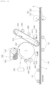
- FIG. 1 schematically illustrates an exemplary embodiment of a printing device of the present disclosure.
- the printing device of the present disclosure relates to technology for printing an image on the surface of a continuously moving metallic material 100 using a roll to roll method.
- the image refers to letters, shapes, pictures, etc., and includes various colors and forms, such as monochromatic, achromatic, and chromatic colors, or three-dimensional form.
- the printing device of the present disclosure includes a transfer belt 800, a photosensitive drum 300, a photosensitive drum charging and discharging unit 400, an exposure unit 200, a developing unit 500, a removal unit 600, a fixing unit 700, etc.
- a transfer belt 800 a transfer belt 800, a photosensitive drum 300, a photosensitive drum charging and discharging unit 400, an exposure unit 200, a developing unit 500, a removal unit 600, a fixing unit 700, etc.
- the transfer belt 800 rotating in one direction, while in close contact with a metallic material 100, serves to deliver a toner attached to the surface thereof to the surface of the metallic material 100 to be fixed thereon, and, at the same time, protect the surface of the photosensitive drum 300 and improve the quality of the image. If hardness of the metallic material 100 is high, the surface of the photosensitive drum 300 may be damaged due to contact between the metallic material 100 and the photosensitive drum 300. In this case, repair and replacement costs for the photosensitive drum 300 may increase and the accuracy of the transferred image may also deteriorate, thereby deteriorating print quality. Therefore, the present disclosure adopts a method in which toner does not move from the photosensitive drum 300 to the metallic material 100, but an image is transferred via the transfer belt 800.
- a transfer belt drive roll 810 is provided to drive the transfer belt 800 in a moving direction, and in order to receive a toner T, a transfer belt charging unit 820 is provided to charge the surface of the transfer belt 800 before the toner T is provided from the photosensitive drum 300, and a corona wire is commonly used.
- a toner removal unit 840 is provided to remove the toner T remaining on the transfer belt after the toner T of the transfer belt 800 is delivered to the metallic material 100 to transfer the image, and a transfer belt discharging unit 830 may be provided to discharge the charge on the transfer belt after the toner T is removed.
- the photosensitive drum 300 rotating in the opposite direction, while in contact with the transfer belt, serves to transfer the toner T attached to the surface thereof to the transfer belt 800.
- the photosensitive drum 300 may be a photosensitive drum commonly used in the art to which the present disclosure pertains and is not particularly limited in type.
- an organic photo conductor (OPC) drum may be used.
- the developing unit 500 is provided on one side of the photosensitive drum 300 and provides the toner T for forming an image on the surface.
- the developing unit 500 may be any developing unit that may provide toner to the photosensitive drum 300 and is not particularly limited in form or shape.
- the developing unit 500 includes a toner container 520 including the toner T and a developing roller 510 delivering the toner from the toner container 520 to the photosensitive drum 300.
- the developing roller 520 is not essential, and in some cases, the toner may be provided directly from the toner container 520 to the photosensitive drum 300.
- the toner T forms an image on the surface of a metallic material
- any toner known to a person skilled in the art to which the present disclosure pertains may be used, without being limited in type.
- a material having a polymer structure may be used.
- materials that may provide various functions e.g., fluorescent materials, magnetic materials, electrically conductive materials, etc.
- materials that may provide various functions may be added to the toner, and not only may an image with a function be implemented, but roughness may be given or a three-dimensional shape may be implemented by using various particles of the toner.
- a photosensitive drum charging unit 410 charging the surface of the photosensitive drum 300 before the toner T is provided may be provided.
- the photosensitive drum charging unit 410 applies electrostatic charge to the surface of the photosensitive drum.
- a corona wire is commonly used as the charging unit.
- An exposure unit 200 applying light energy to the charged surface of the photosensitive drum 300 between the developing unit 500 and the photosensitive drum charging unit 410according to a required image is provided.
- the position of the exposure unit 200 is not important, but the light energy is given to the surface of the photosensitive drum 300 between the developing unit 500 and the photosensitive drum charging unit 410. Due to the light energy, some charges are removed from the surface of the photosensitive drum 300, and the toner is attached to the surface of the photosensitive drum 300 by the developing unit 500.
- the light energy is preferably a laser or a light emitting diode (LED).
- FIG. 2 schematically illustrates the exposure unit 200 in the case of using the laser.
- a scanning mirror 220 removing charges by scanning according to the image required for the surface of the photosensitive drum 300 by regulating the laser generating unit 210 and the laser emitted from the laser generating unit 210 may be provided.
- a metal material charging unit 101 charging the surface of the metallic material 100 may be provided so that the image forming toner T delivered from the photosensitive drum 300 to the transfer belt 800 may move to and settle on the continuously moving metallic material 100.
- the metallic material charging unit 101 not only serves to charge the metallic material with a certain electric charge, but also serves as a guide roll to help the metallic material move at a constant speed.
- One or more metallic material charging unit 101 may be provided, and the metallic material charging unit 101 may be located at the front, rear, or front and rear of the transfer belt 800 based on a moving direction of the metallic material 100 and may be located at the top, bottom, or both top and bottom of the metallic material 100.
- FIG. 3 illustrates another exemplary embodiment in the present disclosure.
- a separate coating layer (A) for example, a resin layer, etc. may be formed on the surface of the metallic material 100, and in the case of printing on the coating layer, a metallic material charging unit 101' for charging the coating layer (A) may be located on the coating layer A.
- the photosensitive drum 300 includes the removal unit 600 removing the toner T remaining on the surface after providing the toner on the surface thereof to the transfer belt 800.
- the removal unit 600 may include a blade 610 separating the remaining toner on the surface of the photosensitive drum 300 and a collection bin 620 for collecting the separated toner at a lower end of the blade 610 to prevent the separated toner from falling to the metallic material 100 and deteriorating printing quality.
- such removal unit may also be provided in the transfer belt 800. That is, after setting the toner T for image formation on the metallic material 100, in order to remove the toner T remaining on the surface of the transfer belt 800, a blade 810 and a collection bin 820 of collecting the separated toner at the lower end of the blade 810 to prevent the separated toner from falling to the metallic material 100 and deteriorating printing quality may be provided.
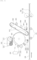
- FIG. 4 schematically illustrates another exemplary embodiment of the printing device of the present disclosure.
- the removal unit 600 removing the toner remaining on the surface of the photosensitive drum 300 after the toner T of the photosensitive drum 300 moves to the surface of the transfer belt 800 is realized, and an alcohol brush 630, in addition to the blade 610 and the collection bin 620 described above, may be further included.
- the photosensitive drum 300 rotates at high speed and transfers an image, so there are cases in which it is not easy to remove the toner. In this case, there is a problem that an afterimage of the image may remain.
- secondary removal may be performed by a chemical method using an alcohol brush or the like. Meanwhile, the alcohol brush for chemical removal may be equally applied to the transfer belt 800.
- a fixing unit 700 may be provided at the rear of the photosensitive drum 300 and the transfer belt 800 based on the moving direction of the metallic material 100 to fix the toner T on the metallic material 100 to stably form an image.
- the fixing unit 700 may include a fused roll 710 applying heat to the toner T to fix the toner T settled on the metallic material 100 and a pressure roll 720 applying pressure to help fix the toner T.
- a heating temperature of the fused roll 710 is preferably 25 to 400°C.
- the metallic material charging unit 101 and the pressure roll 720 have a structure capable of moving up and down.
- the metallic material 100 may not always have a constant thickness and may be a very thin film or a thick plate. Therefore, if the metallic material charging unit 101 and the pressure roll 720 may be moved up and down depending on the thickness of the metallic material 100, an image may be printed regardless of the thickness of the metallic material 100.
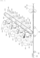
- FIG. 5 schematically illustrates another exemplary embodiment of the printing device of the present disclosure.
- FIG. 5 illustrates a printing device for transferring an image by providing four types of toners in order to print a color image.
- the four types of toners may be C (Cyan), Y (Yellow), and M (Magenta), and K (Black).
- the four types of toners may not be necessarily used, and may include W (White). Some of these may be used, and the order is not set.
- W white
- the white (W) toner may be placed at the front in the direction of the metallic material.
- FIG. 5 illustrates a printing device in the case of using four types of toners.
- four pairs of photosensitive drums 301, 302, 303, and 304, photosensitive drum charging and discharging unit 401, 402, 403, and 404, exposure units 201, 202, 203, and 204, developing units 501, 502, 503, and 504, and removal units 601, 602, 603, and 604 may be located in the moving direction of the transfer belt.
- the toner T transferred by each pair may be delivered to one transfer belt 800, and the transfer belt 800 settles the toner T again on the metallic material 100.
- the fixing unit 700 for fixing the toner settled on the metallic material 100 is for fixing the final transferred image, and does not necessarily need to be multiple.
- transfer belt support rolls 811, 812, 813, and 814 that promote continuous movement, while supporting the transfer belt 800, may be further provided.
- FIG. 6 illustrates another exemplary embodiment in the present disclosure.
- FIG. 6 relates to the aforementioned printing device which may sequentially or simultaneously print both sides of the continuously moving metallic material 100, and illustrates the above-described printing device located above and below the metallic material.
- technology that each component having the functions and roles described above are provided above and below the metallic material to print both front and back sides of the metallic material.
- a surface of a photosensitive drum 300 rotating in one direction is charged.
- a charge layer is formed on the photosensitive drum 300 with a certain charge, and then it is prepared to apply an image using the toner T.
- the surface of the photosensitive drum 300 may have either a positive (+) or negative (-) charge.
- Exposure is performed to provide light energy to the surface of the charged photosensitive drum 300 by forming the charge layer.
- the toner may be moved on the surface of the photosensitive drum 300 according to a required image.
- the light energy may be in various forms, and it is preferable to use a laser or LED light source.
- the toner is attached to the exposed surface of the photosensitive drum 300. This is called the development stage.
- the toner is charged with a charge opposite to that of the photosensitive drum 300 and adheres to the surface of the photosensitive drum 300.
- the developing roller 510 transfers a certain amount of toner T from the toner container 520 to the photosensitive drum 300.
- the developing roller 510 may not be necessary, and the toner T may be moved directly from the toner container 520 to the photosensitive drum 300. That is, the developing operation is a process in which the toner is attached to the position from which the charge was removed from the surface of the photosensitive drum 300.
- the toner attached to the surface of the photosensitive drum 300 moves to the charged transfer belt 800, thereby moving the toner to the surface of the transfer belt 800.
- the surface of the transfer belt 800 is charged with a charge opposite to that of the toner, so the toner is attracted and moved to the surface of the transfer belt 800.
- the transfer belt 800 it is possible to avoid direct contact of the photosensitive drum 300 with the metallic material 100.
- the toner T on the surface of the photosensitive drum 300 is first moved to the transfer belt 800.
- a transfer operation is performed in which the toner attached to the surface of the transfer belt 800 moves to the continuously moving charged metallic material 100 and settled on the surface of the metallic material 100.
- the metallic material 100 is charged with the same charge as that of the transfer belt 800 and is charged with a charge opposite to the toner, so that the toner on the transfer belt moves to the metallic material 100.
- the transfer operation is a process of printing an image on the surface of the metallic material 100, in which since the metallic material 100 is charged with a charge opposite to the toner, thereby attracting the toner and fixing the toner on the surface of the metallic material 100.
- Charging of the metallic material 100 may be performed before, after, or both before and after the transfer operation.
- a metallic material charging unit 101' may be additionally provided for the coating layer (A) to be charged.
- the toner fixed on the surface of the metallic material 100 goes through a fixing operation, and the fixing operation may be performed by thermocompression. Specifically, the toner may be compressed at the same time when heat is applied by the fused roll 710 and the pressure roll 720. At this time, the heating temperature is preferably 25 to 400°C.
- the toner used in the present disclosure is used for printing metallic materials, and a main component thereof has a polymer structure. In particular, because metallic materials have a high heat transfer rate, it may be difficult to melt and adsorb the toner, so the toner should be heated to an appropriate temperature to be adsorbed.
- the heating temperature is preferably 25°C or higher. Meanwhile, if the temperature exceeds 400°C, the polymer structure of the toner may decompose, so it is preferable that the heating temperature does not exceed 400°C. More preferably, the toner is heated to 50 to 300°C.
- a removal operation is performed to remove the toner remaining on the surface of the photosensitive drum 300 and the toner remaining on the surface of the transfer belt 800 after the toner is settled on the metal material 100. This is to prevent a deterioration of printing quality due to an afterimage that may remain in the follow-up printing process due to the toner remaining on the photosensitive drum 300 and the transfer belt 800.
- the removal method physical removal is performed through the blades 610 and 841, and the removed toner may be collected by the collection bins 620 and 842, thereby being prevented from falling onto the metallic material. Meanwhile, for more complete removal, chemical removal may be further performed using the alcohol brush 630 after the physical removal.
- the transfer belt may further include the alcohol brush.
- the printing method of the present disclosure may print a color image using various colors of toners T, such as W (White), C (Cyan), Y (Yellow), M (Magenta), and K (Black).
- printing may be performed using two or more toners, and in this case, as described above, two or more photosensitive drums, photosensitive drum charging units, photosensitive drum discharging units, exposure units, developing units, and removal units may be provided in pairs and are provided in the moving direction of the transfer belt, and as the charging operation, the exposure operation, the developing operation, the transfer operation, and the removal operation are performed twice or more times, printing may be performed in various colors.
- the order of the colors is not particularly limited in the present disclosure and may be determined considering a required image, work efficiency, etc.
- FIG. 5 An example of this is shown in FIG. 5 .
- four pairs of photosensitive drums, a photosensitive drum charging unit, the photosensitive drum discharging units, the exposing units, the developing units, and the removal units are provided in four pairs and perform each operation to perform printing.
- a white background image may be transferred first, which has the advantage of increasing the clarity of the overall image.
- an image may be printed on both sides of the metallic material by sequentially or simultaneously applying the printing method of the present disclosure described above to both the front and rear sides of the metallic material.
- FIG. 7 schematically illustrates the printed metallic material of the present disclosure, and the present disclosure will be described in detail with reference to FIG. 7 .
- the printed metallic material of the present disclosure includes a printed layer formed on the metallic material, as shown in FIG. 7 (a) .
- the metallic materials may include steel sheets, non-ferrous metals, and metal alloys, and are not limited in type.
- the printed layer is preferably formed using the metallic material printing device or the metallic material printing method described above. That is, the printed layer is preferably formed using a printing device and a printing method using a laser, LED, etc. as an exposure unit.
- the printed layer may form more diverse images compared to images formed on existing metallic materials.
- the printed layer has the advantage of not only having a clear shape and color compared to images formed by the existing printing methods, but also having excellent processing characteristics due to high resistance thereof to peeling.
- Existing printing methods include roll coating and inkjet coating using liquid pigments or dyes. This liquid type method uses transparent polymer resin (approximately 70-80 wt%) mixed with colored particles (approximately 20-30 wt%). In other words, since most of the pigments and dyes are transparent polymer resins, the shape or color is not clearly visible, and if liquid particles are large, the possibility of peeling due to stress applied to the entire polymer may increase, so the processing characteristics may be low.
- the printed layer of the present disclosure uses the toner, which is a solid powder, and each particle of the powder corresponds to a unit particle including color, so excellent color may be formed.
- the toner which is a solid powder
- each particle of the powder corresponds to a unit particle including color, so excellent color may be formed.
- existing printing methods use liquid pigments or dyes, they are significantly affected by a surface condition of the printed material. For example, in that printing quality is affected by the surface roughness or surface shape of the material, effort is required for pre-treatment of the surface, such as roughness management.
- the printing method using a laser, LED, etc. according to the present disclosure is a method in which toner powder is printed through an electrical adsorption and compression process, so an image may be formed more easily than the existing method.
- the printed metallic material of the present disclosure may further include a coating layer between the metallic material and the printed layer, as shown in FIG. 7(b) .
- the coating layer may include a wet or dry plating layer, such as an electrogalvanized (EG) layer or a hot dip galvanized (GI) layer.
- the coating layer may include a pretreatment layer formed on the plating layer, an intermediate coating layer formed on the pretreatment layer, and a top coating layer formed on the intermediate coating layer.
- the pretreatment layer, the intermediate coating layer, and the top coating layer are not particularly limited in the present disclosure, and may include all those known in the art to which the present disclosure pertains. Hereinafter, a preferred example will be described.
- the pretreatment layer is intended to improve adhesion between a base metal and the intermediate coating layer (a primer layer) and is usually formed within 1 um, and a chromium-free (Cr-free) polymer coating, chromium hexavalent (Cr6 + ), or chromium trivalent (Cr 3+ ) coating may be performed.
- a chromium-free (Cr-free) polymer coating, chromium hexavalent (Cr6 + ), or chromium trivalent (Cr 3+ ) coating may be performed.
- the intermediate coating layer (the primer layer) is for ensuring corrosion resistance and concealing a base layer, may have about 5 ⁇ m, and may be coated using polyester, urethane, epoxy, etc. However, the intermediate coating layer may be omitted depending on the purpose.
- the top coating layer represents surface properties and is directly related to the physical properties of the product, and the printed layer is formed on the top coating layer. Accordingly, the top coating layer is intended for protection, color, and concealment when the surface is physically hit, and to this end, the top coating layer may have a thickness of 15 to 20 ⁇ m, and polyester, urethane, epoxy, etc. may be used.
- the printed metallic material of the present disclosure may further include a transparent coating layer on the printed layer, as shown in FIGS. 7(c) and 7(d) .
- the transparent coating layer requires gloss or serves to protect the printed layer.
- the transparent coating layer is also not particularly limited in the present disclosure and may include all those known in the art to which the present disclosure pertains.
- the transparent coating layer is generally polymer-based, and polymer resins, such as polyester and urethane, may be used similar to the top coating layer, and in the case of outdoor use, a fluorine resin may be used.
- the transparent coating layer may be formed to have a thickness of about 1 to 5 um depending on the purpose.
Landscapes
- Physics & Mathematics (AREA)
- General Physics & Mathematics (AREA)
- Engineering & Computer Science (AREA)
- Ceramic Engineering (AREA)
- Textile Engineering (AREA)
- Optics & Photonics (AREA)
- Electrostatic Charge, Transfer And Separation In Electrography (AREA)
- Combination Of More Than One Step In Electrophotography (AREA)
- Electrophotography Configuration And Component (AREA)
- Control Or Security For Electrophotography (AREA)
- Color Electrophotography (AREA)
Abstract
Description
- The present disclosure relates to a printing device for printing images, such as letters and pictures, on a surface of a metallic material, such as a steel sheet, and a printing method using the same.
- Methods for printing images, such as letters and pictures, on the surface of metallic materials include a polymer transfer method, a roll transfer method, and an inkjet spray printing method.
- In the polymer transfer method, an image film in the form of a sheet is output and an image is transferred to the surface of metal in a manner of thermal transfer or chemical transfer. The method of transferring images to a metal surface using a film is free to output on a film, but a manufacturing speed is slow as the film is transferred to a steel sheet, and the image attached to the metal surface in the form of a film may change depending on temperature or weather.
- The roll transfer method is a method of forming a certain pattern on a surface of a roll and transferring an image to a surface of a metallic material in a roll-to-roll manner. However, the transferred images are limited to repetitive images, and in order to use the roll transfer method, a roll with each image patterned thereon should be prepared, making it difficult to prepare a patterned roll each time for various images.
- The inkjet spray printing method is a method of printing images or letters on the surface of a metallic material using liquid ink including pigment and polymer resin. The inkjet spray printing method has a problem in that the surface of the metallic material should be plasma-treated or surface roughness should be controlled so that liquid may be easily adsorbed onto the surface of the steel sheet in using liquid ink. In addition, since the inkjet spray printing method uses liquid ink, a nozzle through which ink is sprayed may be clogged, requiring not only nozzle management but also periodic cleaning and replacement of the nozzle. In addition, since liquid ink is used, stabilization after ink spraying is essential, and it is difficult to manufacture using the roll-to-roll method and its use is limited to a batch type. In particular, inkjet spray printing materials have a form in which liquid polymers are connected and pigment forms an image therein, so there may be a problem in that the printed image may peel off in the case of bending or cutting.
- Recently, metallic materials have been used in various fields, and images, such as letters and pictures, have been increasingly applied to metal surfaces in many cases. However, the existing image printing method is a method of printing images on the surface of paper or polymer materials, and there are technical and production limitations in applying images to the surface of metallic materials. Therefore, there is a need for a method to solve the limitations of the conventional printing method.
- An aspect of the present disclosure is to provide a printing device capable of stably printing images on the surface of a metallic material at a high speed and a printing method using the same, as technology for printing images, such as letters and pictures, on the surface of a metallic material.
- In addition, an aspect of the present disclosure is to improve lifespan and printing yield of a photosensitive drum by avoiding direct contact between a metallic material and the photosensitive drum during a printing process of a metallic material.
- The object of the present disclosure is not limited to the above-mentioned matters. Additional objects of the present disclosure are described throughout the specification, and those skilled in the art may not have any difficulty in understanding the additional objects of the present disclosure from the description given in the specification of the present disclosure.
- According to an aspect of the present disclosure, a printing device for a metallic material includes: a
transfer belt 800, which is in close contact with a continuously movingmetallic material 100 and rotates in one direction, transferring a toner T attached to a surface thereof to a surface of ametallic material 100 to be settled thereon; - a
photosensitive drum 300, which is in close contact with thetransfer belt 800 and rotates in a direction, opposite to thetransfer belt 800, transferring the toner T attached to a surface thereof to a surface of thetransfer belt 800; - a developing
unit 500 provided on one side of thephotosensitive drum 300 and providing the toner T to the surface of thephotosensitive drum 300; - a photosensitive
drum charging unit 410 charging the surface of thephotosensitive drum 300 before the toner T is provided; - an
exposure unit 200 applying light energy to the surface of thephotosensitive drum 300 between the developingunit 500 and the photosensitivedrum charging unit 410 according to a required image; - a metallic
material charging unit 101 charging the surface of themetallic material 100 so that the toner T attached to the surface of thetransfer belt 800 is delivered to the surface of themetallic material 100; - a
removal unit 600 removing the toner T remaining on the surface of thephotosensitive drum 300 after the toner T is settled on the surface of themetallic material 100; - a photosensitive
drum discharging unit 420 removing the charge from thephotosensitive drum 300 after removing the toner T; and - a
fixing unit 700 located at a rear end of thetransfer belt 800 - to fix the toner T settled on the surface of the
metallic material 100. - According to another aspect of the present disclosure, a printing method for a metallic material includes a charging operation of charging a surface of a
photosensitive drum 300 rotating in one direction; - an exposure operation of applying light energy to the surface of the charged
photosensitive drum 300 according to a required image; - a developing operation of providing toner T to the surface of the
photosensitive drum 300 after the exposure; - moving the toner attached to the surface of the
photosensitive drum 300 to a surface of thecharged transfer belt 800; - a transfer operation of continuously moving the toner attached to the surface of the
transfer belt 800 and moving the toner to a surface of a chargedmetallic material 100 to settle the toner thereon; - a fixing operation of fixing the toner settled on the surface of the
metallic material 100; - a removal operation of removing the toner remaining on the surfaces of the
photosensitive drum 300 and thetransfer belt 800 after the transfer; and - a discharging operation of discharging
- the surfaces of the
photosensitive drum 300 and thetransfer belt 800. - According to the present disclosure, technology capable of stably printing images, such as letters and pictures, on materials, such as metal, may be provided, and production efficiency of products may be improved by continuously manufacturing products. In addition, high value-added products may be manufactured by easily forming diverse and colorful images.
- Moreover, according to the present disclosure, by preventing direct contact between metallic materials and the photosensitive drum, damage to and wear of the photosensitive drum may be minimized, thereby reducing repair efforts for the photosensitive drum and improving lifespan of the photosensitive drum.
- The various and beneficial advantages and effects of the present disclosure are not limited to the aforementioned contents and may be more easily understood through description of specific exemplary embodiments of the present disclosure.
-
-
FIG. 1 is a schematic diagram schematically illustrating an exemplary embodiment of a printing device of the present disclosure. -
FIG. 2 is a schematic diagram specifically illustrating an example of a laser exposure unit in the printing device of the present disclosure. -
FIG. 3 is a schematic diagram schematically illustrating another exemplary embodiment of the printing device of the present disclosure. -
FIG. 4 is a schematic diagram schematically illustrating another exemplary embodiment of the printing device of the present disclosure. -
FIG. 5 is a schematic diagram schematically illustrating another exemplary embodiment of the printing device of the present disclosure. -
FIG. 6 is a schematic diagram schematically illustrating another exemplary embodiment of the printing device of the present disclosure. -
FIG. 7 is a schematic diagram schematically illustrating a cross-section of a printed metallic material of the present disclosure. - The terms used in this specification are for describing the present disclosure and are not intended to limit the present disclosure. In addition, as used herein, singular forms include plural forms unless the relevant definition clearly indicates to the contrary.
- The meaning of "including" used in the specification specifies a component and does not exclude the presence or addition of another component.
- Unless otherwise defined, all terms, including technical and scientific terms, used in this specification have the same meaning as commonly understood by the person skilled in the art to which the present disclosure pertains. Terms defined in the dictionary are interpreted to have meanings consistent with related technical document and present disclosure.
- Generally known laser or LED printers are used to print on flexible objects, such as paper, but the present disclosure relates to technology for printing images on metallic materials. The present disclosure uses a charging unit, a photosensitive drum, a fused roll, etc. to print images on the surface of a continuously moving metallic material in a roll-to-roll manner. The present disclosure relates to technology using a transfer belt to prevent the surface of a photosensitive drum from being damaged by frictional contact between the photosensitive drum and the metallic material when the metallic material has high hardness.
- Hereinafter, exemplary embodiments of the present disclosure will be described with reference to the drawings. The exemplary embodiments of the present disclosure may be modified in various forms, should not be construed as being limited to the drawings and the exemplary embodiments described below, and are described in detail to those skilled in the art to which the present disclosure pertains.
-
FIG. 1 schematically illustrates an exemplary embodiment of a printing device of the present disclosure. Referring toFIG. 1 , the printing device of the present disclosure relates to technology for printing an image on the surface of a continuously movingmetallic material 100 using a roll to roll method. The image refers to letters, shapes, pictures, etc., and includes various colors and forms, such as monochromatic, achromatic, and chromatic colors, or three-dimensional form. - The printing device of the present disclosure includes a
transfer belt 800, aphotosensitive drum 300, a photosensitive drum charging and dischargingunit 400, anexposure unit 200, a developingunit 500, aremoval unit 600, a fixingunit 700, etc. Hereinafter, each component will be described in detail. - The
transfer belt 800, rotating in one direction, while in close contact with ametallic material 100, serves to deliver a toner attached to the surface thereof to the surface of themetallic material 100 to be fixed thereon, and, at the same time, protect the surface of thephotosensitive drum 300 and improve the quality of the image. If hardness of themetallic material 100 is high, the surface of thephotosensitive drum 300 may be damaged due to contact between themetallic material 100 and thephotosensitive drum 300. In this case, repair and replacement costs for thephotosensitive drum 300 may increase and the accuracy of the transferred image may also deteriorate, thereby deteriorating print quality. Therefore, the present disclosure adopts a method in which toner does not move from thephotosensitive drum 300 to themetallic material 100, but an image is transferred via thetransfer belt 800. - Meanwhile, a transfer
belt drive roll 810 is provided to drive thetransfer belt 800 in a moving direction, and in order to receive a toner T, a transferbelt charging unit 820 is provided to charge the surface of thetransfer belt 800 before the toner T is provided from thephotosensitive drum 300, and a corona wire is commonly used. Meanwhile, atoner removal unit 840 is provided to remove the toner T remaining on the transfer belt after the toner T of thetransfer belt 800 is delivered to themetallic material 100 to transfer the image, and a transferbelt discharging unit 830 may be provided to discharge the charge on the transfer belt after the toner T is removed. - The
photosensitive drum 300, rotating in the opposite direction, while in contact with the transfer belt, serves to transfer the toner T attached to the surface thereof to thetransfer belt 800. Thephotosensitive drum 300 may be a photosensitive drum commonly used in the art to which the present disclosure pertains and is not particularly limited in type. For example, an organic photo conductor (OPC) drum may be used. - The developing
unit 500 is provided on one side of thephotosensitive drum 300 and provides the toner T for forming an image on the surface. The developingunit 500 may be any developing unit that may provide toner to thephotosensitive drum 300 and is not particularly limited in form or shape. InFIG. 1 , as a preferred example, the developingunit 500 includes atoner container 520 including the toner T and a developingroller 510 delivering the toner from thetoner container 520 to thephotosensitive drum 300. The developingroller 520 is not essential, and in some cases, the toner may be provided directly from thetoner container 520 to thephotosensitive drum 300. Meanwhile, the toner T forms an image on the surface of a metallic material, and any toner known to a person skilled in the art to which the present disclosure pertains may be used, without being limited in type. For example, a material having a polymer structure may be used. In addition, in the present disclosure, materials that may provide various functions (e.g., fluorescent materials, magnetic materials, electrically conductive materials, etc.) may be added to the toner, and not only may an image with a function be implemented, but roughness may be given or a three-dimensional shape may be implemented by using various particles of the toner. - A photosensitive
drum charging unit 410 charging the surface of thephotosensitive drum 300 before the toner T is provided may be provided. The photosensitivedrum charging unit 410 applies electrostatic charge to the surface of the photosensitive drum. As the charging unit, a corona wire is commonly used. - An
exposure unit 200 applying light energy to the charged surface of thephotosensitive drum 300 between the developingunit 500 and the photosensitive drum charging unit 410according to a required image is provided. The position of theexposure unit 200 is not important, but the light energy is given to the surface of thephotosensitive drum 300 between the developingunit 500 and the photosensitivedrum charging unit 410. Due to the light energy, some charges are removed from the surface of thephotosensitive drum 300, and the toner is attached to the surface of thephotosensitive drum 300 by the developingunit 500. The light energy is preferably a laser or a light emitting diode (LED).FIG. 2 schematically illustrates theexposure unit 200 in the case of using the laser. Ascanning mirror 220 removing charges by scanning according to the image required for the surface of thephotosensitive drum 300 by regulating thelaser generating unit 210 and the laser emitted from thelaser generating unit 210 may be provided. - A metal
material charging unit 101 charging the surface of themetallic material 100 may be provided so that the image forming toner T delivered from thephotosensitive drum 300 to thetransfer belt 800 may move to and settle on the continuously movingmetallic material 100. The metallicmaterial charging unit 101 not only serves to charge the metallic material with a certain electric charge, but also serves as a guide roll to help the metallic material move at a constant speed. One or more metallicmaterial charging unit 101 may be provided, and the metallicmaterial charging unit 101 may be located at the front, rear, or front and rear of thetransfer belt 800 based on a moving direction of themetallic material 100 and may be located at the top, bottom, or both top and bottom of themetallic material 100. - Even if there are two or more metallic
material charging unit 101, they do not play different roles and there is an advantage in that stronger electrostatic attraction may be secured through charging two or more times. - Meanwhile,
FIG. 3 illustrates another exemplary embodiment in the present disclosure. As shown inFIG. 3 , a separate coating layer (A), for example, a resin layer, etc. may be formed on the surface of themetallic material 100, and in the case of printing on the coating layer, a metallic material charging unit 101' for charging the coating layer (A) may be located on the coating layer A. - The
photosensitive drum 300 includes theremoval unit 600 removing the toner T remaining on the surface after providing the toner on the surface thereof to thetransfer belt 800. Theremoval unit 600 may include ablade 610 separating the remaining toner on the surface of thephotosensitive drum 300 and acollection bin 620 for collecting the separated toner at a lower end of theblade 610 to prevent the separated toner from falling to themetallic material 100 and deteriorating printing quality. - Meanwhile, such removal unit may also be provided in the
transfer belt 800. That is, after setting the toner T for image formation on themetallic material 100, in order to remove the toner T remaining on the surface of thetransfer belt 800, ablade 810 and acollection bin 820 of collecting the separated toner at the lower end of theblade 810 to prevent the separated toner from falling to themetallic material 100 and deteriorating printing quality may be provided. -
FIG. 4 schematically illustrates another exemplary embodiment of the printing device of the present disclosure. In the printing device shown inFIG. 4 , theremoval unit 600 removing the toner remaining on the surface of thephotosensitive drum 300 after the toner T of thephotosensitive drum 300 moves to the surface of thetransfer belt 800 is realized, and analcohol brush 630, in addition to theblade 610 and thecollection bin 620 described above, may be further included. Thephotosensitive drum 300 rotates at high speed and transfers an image, so there are cases in which it is not easy to remove the toner. In this case, there is a problem that an afterimage of the image may remain. To this end, after primary removal with theblade 610, secondary removal may be performed by a chemical method using an alcohol brush or the like. Meanwhile, the alcohol brush for chemical removal may be equally applied to thetransfer belt 800. - A fixing
unit 700 may be provided at the rear of thephotosensitive drum 300 and thetransfer belt 800 based on the moving direction of themetallic material 100 to fix the toner T on themetallic material 100 to stably form an image. The fixingunit 700 may include a fusedroll 710 applying heat to the toner T to fix the toner T settled on themetallic material 100 and apressure roll 720 applying pressure to help fix the toner T. At this time, a heating temperature of the fusedroll 710 is preferably 25 to 400°C. - In the present disclosure, it is more preferable that the metallic
material charging unit 101 and thepressure roll 720 have a structure capable of moving up and down. Themetallic material 100 may not always have a constant thickness and may be a very thin film or a thick plate. Therefore, if the metallicmaterial charging unit 101 and thepressure roll 720 may be moved up and down depending on the thickness of themetallic material 100, an image may be printed regardless of the thickness of themetallic material 100. - Meanwhile, one or more toners may be used to print various images, and in this case, two or more photosensitive drums, two or more photosensitive drum charging units, two or more photosensitive drum discharging units, two or more exposure units, two or more developing units, and two or more removal units may be provided in pairs in the moving direction of the
transfer belt 800.FIG. 5 schematically illustrates another exemplary embodiment of the printing device of the present disclosure.FIG. 5 illustrates a printing device for transferring an image by providing four types of toners in order to print a color image. The four types of toners may be C (Cyan), Y (Yellow), and M (Magenta), and K (Black). The four types of toners may not be necessarily used, and may include W (White). Some of these may be used, and the order is not set. A person skilled in the art may arbitrarily select one considering a required image, work efficiency, etc. However, the white (W) toner may be placed at the front in the direction of the metallic material. -
FIG. 5 illustrates a printing device in the case of using four types of toners. Accordingly, inFIG. 5 , in order to settle the four types of toners on themetallic material 100, four pairs ofphotosensitive drums unit exposure units units removal units FIG. 5 , the toner T transferred by each pair may be delivered to onetransfer belt 800, and thetransfer belt 800 settles the toner T again on themetallic material 100. In addition, at this time, the fixingunit 700 for fixing the toner settled on themetallic material 100 is for fixing the final transferred image, and does not necessarily need to be multiple. - Meanwhile, as shown in
FIG. 5 , in the case of using multiple photosensitive drums, the length of thetransfer belt 800 may increase, which may cause sagging. Therefore, transfer belt support rolls 811, 812, 813, and 814 that promote continuous movement, while supporting thetransfer belt 800, may be further provided. -
FIG. 6 illustrates another exemplary embodiment in the present disclosure.FIG. 6 relates to the aforementioned printing device which may sequentially or simultaneously print both sides of the continuously movingmetallic material 100, and illustrates the above-described printing device located above and below the metallic material. In other words, technology that each component having the functions and roles described above are provided above and below the metallic material to print both front and back sides of the metallic material. - Hereinafter, a metallic material printing method of the present disclosure will be described in detail. The printing method of the present disclosure will be described with reference to the drawings described above.
- In the present disclosure, in the printing method for printing an image on the surface of the continuously moving
metallic material 100, first, a surface of aphotosensitive drum 300 rotating in one direction is charged. Through this, a charge layer is formed on thephotosensitive drum 300 with a certain charge, and then it is prepared to apply an image using the toner T. The surface of thephotosensitive drum 300 may have either a positive (+) or negative (-) charge. - Exposure is performed to provide light energy to the surface of the charged
photosensitive drum 300 by forming the charge layer. By removing the charge on the surface of thephotosensitive drum 300, the toner may be moved on the surface of thephotosensitive drum 300 according to a required image. The light energy may be in various forms, and it is preferable to use a laser or LED light source. - The toner is attached to the exposed surface of the
photosensitive drum 300. This is called the development stage. The toner is charged with a charge opposite to that of thephotosensitive drum 300 and adheres to the surface of thephotosensitive drum 300. In the developing operation, referring to the example ofFIG. 1 , the developingroller 510 transfers a certain amount of toner T from thetoner container 520 to thephotosensitive drum 300. However, the developingroller 510 may not be necessary, and the toner T may be moved directly from thetoner container 520 to thephotosensitive drum 300. That is, the developing operation is a process in which the toner is attached to the position from which the charge was removed from the surface of thephotosensitive drum 300. - Thereafter, the toner attached to the surface of the
photosensitive drum 300 moves to the chargedtransfer belt 800, thereby moving the toner to the surface of thetransfer belt 800. At this time, the surface of thetransfer belt 800 is charged with a charge opposite to that of the toner, so the toner is attracted and moved to the surface of thetransfer belt 800. By using thetransfer belt 800, it is possible to avoid direct contact of thephotosensitive drum 300 with themetallic material 100. In particular, in order to prevent the surface of the photosensitive drum from being damaged in the case of using a metallic material with high hardness, the toner T on the surface of thephotosensitive drum 300 is first moved to thetransfer belt 800. - As described above, a transfer operation is performed in which the toner attached to the surface of the
transfer belt 800 moves to the continuously moving chargedmetallic material 100 and settled on the surface of themetallic material 100. Themetallic material 100 is charged with the same charge as that of thetransfer belt 800 and is charged with a charge opposite to the toner, so that the toner on the transfer belt moves to themetallic material 100. The transfer operation is a process of printing an image on the surface of themetallic material 100, in which since themetallic material 100 is charged with a charge opposite to the toner, thereby attracting the toner and fixing the toner on the surface of themetallic material 100. Charging of themetallic material 100 may be performed before, after, or both before and after the transfer operation. Meanwhile, as shown inFIG. 3 , when a separate coating layer (A) is formed on the surface of themetallic material 100 and printing is performed on the coating layer (A), a metallic material charging unit 101' may be additionally provided for the coating layer (A) to be charged. - The toner fixed on the surface of the
metallic material 100 goes through a fixing operation, and the fixing operation may be performed by thermocompression. Specifically, the toner may be compressed at the same time when heat is applied by the fusedroll 710 and thepressure roll 720. At this time, the heating temperature is preferably 25 to 400°C. As described above, the toner used in the present disclosure is used for printing metallic materials, and a main component thereof has a polymer structure. In particular, because metallic materials have a high heat transfer rate, it may be difficult to melt and adsorb the toner, so the toner should be heated to an appropriate temperature to be adsorbed. To this end, since the toner may be reacted at a temperature above room temperature and may be fixed to the surface of the metallic material, the heating temperature is preferably 25°C or higher. Meanwhile, if the temperature exceeds 400°C, the polymer structure of the toner may decompose, so it is preferable that the heating temperature does not exceed 400°C. More preferably, the toner is heated to 50 to 300°C. - After the toner is moved to the
transfer belt 800, a removal operation is performed to remove the toner remaining on the surface of thephotosensitive drum 300 and the toner remaining on the surface of thetransfer belt 800 after the toner is settled on themetal material 100. This is to prevent a deterioration of printing quality due to an afterimage that may remain in the follow-up printing process due to the toner remaining on thephotosensitive drum 300 and thetransfer belt 800. At this time, as shown inFIGS. 1 and4 , in the removal method, physical removal is performed through theblades collection bins alcohol brush 630 after the physical removal. Although not shown in the present disclosure, in some cases, the transfer belt may further include the alcohol brush. - Thereafter, in order to extinguish the charges remaining on the
photosensitive drum 300 and thetransfer belt 800, an operation of discharging the surfaces of thephotosensitive drum 300 and thetransfer belt 800 is performed. Through the discharge, thephotosensitive drum 300 is prepared for new printing. - The printing method of the present disclosure may print a color image using various colors of toners T, such as W (White), C (Cyan), Y (Yellow), M (Magenta), and K (Black). At this time, printing may be performed using two or more toners, and in this case, as described above, two or more photosensitive drums, photosensitive drum charging units, photosensitive drum discharging units, exposure units, developing units, and removal units may be provided in pairs and are provided in the moving direction of the transfer belt, and as the charging operation, the exposure operation, the developing operation, the transfer operation, and the removal operation are performed twice or more times, printing may be performed in various colors. The order of the colors is not particularly limited in the present disclosure and may be determined considering a required image, work efficiency, etc.
- An example of this is shown in
FIG. 5 . InFIG. 5 , four pairs of photosensitive drums, a photosensitive drum charging unit, the photosensitive drum discharging units, the exposing units, the developing units, and the removal units are provided in four pairs and perform each operation to perform printing. Meanwhile, when the white toner is used at the forefront based on the moving direction of the metallic material, a white background image may be transferred first, which has the advantage of increasing the clarity of the overall image. - Meanwhile, as shown in
FIG. 6 , in order to print on both the front and rear sides of the metallic material, an image may be printed on both sides of the metallic material by sequentially or simultaneously applying the printing method of the present disclosure described above to both the front and rear sides of the metallic material. - Next, the printed metallic material obtained using the above printing device or printing method will be described in detail.
FIG. 7 schematically illustrates the printed metallic material of the present disclosure, and the present disclosure will be described in detail with reference toFIG. 7 . - The printed metallic material of the present disclosure includes a printed layer formed on the metallic material, as shown in
FIG. 7 (a) . As described above, the metallic materials may include steel sheets, non-ferrous metals, and metal alloys, and are not limited in type. - The printed layer is preferably formed using the metallic material printing device or the metallic material printing method described above. That is, the printed layer is preferably formed using a printing device and a printing method using a laser, LED, etc. as an exposure unit.
- The printed layer may form more diverse images compared to images formed on existing metallic materials. The printed layer has the advantage of not only having a clear shape and color compared to images formed by the existing printing methods, but also having excellent processing characteristics due to high resistance thereof to peeling. Existing printing methods include roll coating and inkjet coating using liquid pigments or dyes. This liquid type method uses transparent polymer resin (approximately 70-80 wt%) mixed with colored particles (approximately 20-30 wt%). In other words, since most of the pigments and dyes are transparent polymer resins, the shape or color is not clearly visible, and if liquid particles are large, the possibility of peeling due to stress applied to the entire polymer may increase, so the processing characteristics may be low. In contrast, the printed layer of the present disclosure uses the toner, which is a solid powder, and each particle of the powder corresponds to a unit particle including color, so excellent color may be formed. In addition, because existing printing methods use liquid pigments or dyes, they are significantly affected by a surface condition of the printed material. For example, in that printing quality is affected by the surface roughness or surface shape of the material, effort is required for pre-treatment of the surface, such as roughness management. However, the printing method using a laser, LED, etc. according to the present disclosure is a method in which toner powder is printed through an electrical adsorption and compression process, so an image may be formed more easily than the existing method.
- Meanwhile, the printed metallic material of the present disclosure may further include a coating layer between the metallic material and the printed layer, as shown in
FIG. 7(b) . The coating layer may include a wet or dry plating layer, such as an electrogalvanized (EG) layer or a hot dip galvanized (GI) layer. - In addition, the coating layer may include a pretreatment layer formed on the plating layer, an intermediate coating layer formed on the pretreatment layer, and a top coating layer formed on the intermediate coating layer.
- The pretreatment layer, the intermediate coating layer, and the top coating layer are not particularly limited in the present disclosure, and may include all those known in the art to which the present disclosure pertains. Hereinafter, a preferred example will be described.
- The pretreatment layer is intended to improve adhesion between a base metal and the intermediate coating layer (a primer layer) and is usually formed within 1 um, and a chromium-free (Cr-free) polymer coating, chromium hexavalent (Cr6+), or chromium trivalent (Cr3+) coating may be performed.
- The intermediate coating layer (the primer layer) is for ensuring corrosion resistance and concealing a base layer, may have about 5 µm, and may be coated using polyester, urethane, epoxy, etc. However, the intermediate coating layer may be omitted depending on the purpose.
- The top coating layer represents surface properties and is directly related to the physical properties of the product, and the printed layer is formed on the top coating layer. Accordingly, the top coating layer is intended for protection, color, and concealment when the surface is physically hit, and to this end, the top coating layer may have a thickness of 15 to 20 µm, and polyester, urethane, epoxy, etc. may be used.
- Meanwhile, the printed metallic material of the present disclosure may further include a transparent coating layer on the printed layer, as shown in
FIGS. 7(c) and 7(d) . The transparent coating layer requires gloss or serves to protect the printed layer. The transparent coating layer is also not particularly limited in the present disclosure and may include all those known in the art to which the present disclosure pertains. - For example, the transparent coating layer is generally polymer-based, and polymer resins, such as polyester and urethane, may be used similar to the top coating layer, and in the case of outdoor use, a fluorine resin may be used. The transparent coating layer may be formed to have a thickness of about 1 to 5 um depending on the purpose.
-
- 100..... METALLIC MATERIAL
- 101, 101'....METALLIC MATERIAL CHARGING UNIT
- 200, 200', 201, 202, 203, 204....EXPOSURE UNIT
- 210.....LASER GENERATING DEVICE
- 220.....SCANNING MIRROR
- 300, 300', 301, 302, 303, 304..... PHOTOSENSITIVE DRUM
- 400, 400', 401, 402, 403, 404... PHOTOSENSITIVE DRUM CHARGING AND DISCHARGING UNIT
- 410, 410', 411, 412, 413, 414... PHOTOSENSITIVE DRUM CHARGING UNIT
- 420, 420', 421, 422, 423, 424... PHOTOSENSITIVE DRUM DISCHARGE UNIT
- 500, 500', 501, 502, 503, 504.....DEVELOPMENT UNIT
- 510, 510', 511, 512, 513, 514.....DEVELOPMENT ROLLER
- 520, 520', 521, 522, 523, 524.....TONER CONTAINER
- 600, 600', 601, 602, 603, 604.....REMOVAL UNIT
- 610, 610', 611, 612, 613, 614 ..... BLADE
- 620, 620', 621, 622, 623, 624.....COLLECTION BIN
- 630.....ALCOHOL BRUSH
- 700, 700'.....FIXING UNIT
- 710, 710'.....FUSED ROLL
- 720.....PRESSURE ROLL
- 800, 800'.....TRANSFER BELT
- 810, 810'.....TRANSFER BELT DRIVE ROLL
- 811, 812, 813, 814 ..... TRANSFER BELT SUPPORT ROLL
- 820, 820'.....TRANSFER BELT CHARGING UNIT
- 830, 830'.....TRANSFER BELT DISCHARGING UNIT
- 840, 840'....TRANSFER BELT TONER REMOVAL UNIT
- 841, 841'.....TRANSFER BELT BLADE
- 842, 842'.....TRANSFER BELT COLLECTION BIN
Claims (16)
- A printing device for a metallic material, the printing device comprising:a transfer belt 800, which is in close contact with a continuously moving metallic material 100 and rotates in one direction, transferring a toner T attached to a surface thereof to a surface of a metallic material 100 to be settled thereon;a photosensitive drum 300, which is in close contact with the transfer belt 800 and rotates in a direction, opposite to the transfer belt 800, transferring the toner T attached to a surface thereof to a surface of the transfer belt 800;a developing unit 500 provided on one side of the photosensitive drum 300 and providing the toner T to the surface of the photosensitive drum 300;a photosensitive drum charging unit 410 charging the surface of the photosensitive drum 300 before the toner T is provided;an exposure unit 200 applying light energy to the surface of the photosensitive drum 300 according to a required image between the developing unit 500 and the photosensitive drum charging unit 410;a metallic material charging unit 101 charging the surface of the metallic material 100 so that the toner T attached to the surface of the transfer belt 800 is delivered to the surface of the metallic material 100;a removal unit 600 removing the toner T remaining on the surface of the photosensitive drum 300 after the toner T is settled on the surface of the metallic material 100;a photosensitive drum discharging unit 420 removing the charge from the photosensitive drum 300 after removing the toner T; anda fixing unit 700 located at a rear end of the transfer belt 800 to fix the toner T settled on the surface of the metallic material 100.
- The printing device of claim 1, wherein
the printing device includes:a transfer belt drive roll 810 driving the transfer belt 800 in a moving direction;a transfer belt charging unit 820 charging the transfer belt 800 before receiving the toner T through the transfer belt 800;a transfer belt toner removal unit 840 removing the toner T remaining on the transfer belt after delivering the toner T to the metallic material 100; anda transfer belt discharging unit 830 discharging the transfer belt after removing the toner T; - The printing device of claim 1, wherein the removal unit 600 includes a blade 610 and a collection bin 620 located at a lower end of the blade 610.
- The printing device of claim 2, wherein the transfer belt toner removal unit 840 includes a blade 841 and a collection bin 842 located at a lower end of the blade 841.
- The printing device of claim 3, wherein the removal unit 600 further includes an alcohol brush 630 between the blade 610 and the collection bin 620.
- The printing device of claim 1, wherein the light energy uses a laser or a light emitting diode (LED).
- The printing device of claim 4, wherein when the light energy is a laser, the exposure unit 200 includes a laser generating unit 210 and a scanning mirror 220.
- The printing device of claim 1, wherein the metallic material charging unit 101 is more than one and is provided at any one of front, rear, and front and rear of the transfer belt 800 based on a moving direction of the metallic material 100.
- The printing device of claim 1, wherein the developing unit 500 includes a toner T container 520 and a developing roller 510 providing the toner T of the toner T container 520 to the photosensitive drum 300.
- The printing device of claim 1, wherein the fixing unit 700 includes a fused roll 710 and a pressure roll 720.
- The printing device of claim 1, whereinthe photosensitive drum, the photosensitive drum charging unit, the photosensitive drum discharging unit, the exposure unit, the developing unit, and the removal unit are formed in pairs and are provided in two or more units according to a moving direction of the transfer belt 800, andeach developing unit provides different colors of toners.
- The printing device of any one of claims 1 to 11, wherein the metallic material printing device is located in upper or lower portions of the metallic material.
- A printing method for a metallic material, the printing method comprising:a charging operation of charging a surface of a photosensitive drum 300 rotating in one direction;an exposure operation of applying light energy to the surface of the charged photosensitive drum 300 according to a required image;a developing operation of providing toner T to the surface of the photosensitive drum 300 after the exposure;moving the toner attached to the surface of the photosensitive drum 300 to a surface of the charged transfer belt 800;a transfer operation of continuously moving the toner attached to the surface of the transfer belt 800 and moving the toner to a surface of a charged metallic material 100 to settle the toner thereon;a fixing operation of fixing the toner settled on the surface of the metallic material 100;a removal operation of removing the toner remaining on the surfaces of the photosensitive drum 300 and the transfer belt 800 after the transfer; anda discharging operation of discharging the surfaces of the photosensitive drum 300 and the transfer belt 800.
- The printing method of claim 13, wherein, in the fixing operation, heating is performed to 25 to 400°C.
- The printing method of claim 13 or 14, wherein, in the fixing operation, pressing is additionally performed.
- The printing method of claim 13, whereinthe above printing method requires two or more photosensitive drums in a case of printing using two or more toners, andperforming two or more of the charging operation, the exposure operation, the developing operation, the transfer operation, and the removal operation using each photosensitive drum.
Applications Claiming Priority (2)
| Application Number | Priority Date | Filing Date | Title |
|---|---|---|---|
| KR1020210090916A KR102784065B1 (en) | 2021-07-12 | 2021-07-12 | Printing facilities for metallic material and printing methof using same |
| PCT/KR2022/010078 WO2023287144A1 (en) | 2021-07-12 | 2022-07-12 | Printing equipment for metallic material and printing method using same |
Publications (2)
| Publication Number | Publication Date |
|---|---|
| EP4372474A1 true EP4372474A1 (en) | 2024-05-22 |
| EP4372474A4 EP4372474A4 (en) | 2024-11-13 |
Family
ID=84920161
Family Applications (1)
| Application Number | Title | Priority Date | Filing Date |
|---|---|---|---|
| EP22842406.5A Pending EP4372474A4 (en) | 2021-07-12 | 2022-07-12 | PRINTING DEVICE FOR METALLIC MATERIAL AND PRINTING METHOD THEREOF |
Country Status (6)
| Country | Link |
|---|---|
| US (1) | US20240385563A1 (en) |
| EP (1) | EP4372474A4 (en) |
| JP (1) | JP2024524573A (en) |
| KR (1) | KR102784065B1 (en) |
| CN (1) | CN117616347A (en) |
| WO (1) | WO2023287144A1 (en) |
Families Citing this family (2)
| Publication number | Priority date | Publication date | Assignee | Title |
|---|---|---|---|---|
| KR102753154B1 (en) * | 2023-12-21 | 2025-01-15 | 주식회사 옴니코트 | Printing apparatus for metallic material |
| KR102753155B1 (en) * | 2023-12-21 | 2025-01-14 | 주식회사 옴니코트 | Printing method for metallic material |
Family Cites Families (27)
| Publication number | Priority date | Publication date | Assignee | Title |
|---|---|---|---|---|
| CA948011A (en) * | 1970-09-25 | 1974-05-28 | Hiroshi Nagame | Method and apparatus for electrophotography |
| AU1548088A (en) * | 1987-04-03 | 1988-11-02 | Toyo Seikan Kaisha Ltd. | Method of multicolor printing metal containers and metal sheets and printed products |
| JPH01163092A (en) * | 1987-09-10 | 1989-06-27 | Ueno Hiroshi | Multicolor printing method for sheet metal |
| MY113259A (en) * | 1990-10-03 | 2002-01-31 | Kk Sato | Xerographic apparatus for label printer |
| JPH0640005A (en) * | 1992-07-22 | 1994-02-15 | Nkk Corp | Method and apparatus for manufacturing printed metal plate |
| JPH0635239A (en) * | 1992-07-22 | 1994-02-10 | Nkk Corp | Method and device for producing printing metallic plate |
| JPH0651573A (en) * | 1992-08-04 | 1994-02-25 | Nkk Corp | Method and apparatus for manufacturing printed metal plate |
| JPH08292614A (en) * | 1995-04-20 | 1996-11-05 | Hitachi Koki Co Ltd | Image recording electrophotographic device |
| US5712073A (en) * | 1996-01-10 | 1998-01-27 | Canon Kabushiki Kaisha | Toner for developing electrostatic image, apparatus unit and image forming method |
| JP3406453B2 (en) * | 1996-04-04 | 2003-05-12 | 富士ゼロックス株式会社 | Double-sided image forming method and apparatus |
| CN1123805C (en) * | 1998-11-24 | 2003-10-08 | 株式会社理光 | Deionization tech. in image forming appts. and improvement in its cleaning tech |
| JP3924464B2 (en) * | 2000-12-28 | 2007-06-06 | 株式会社リコー | Brush processing apparatus and image forming apparatus |
| JP2005017424A (en) * | 2003-06-24 | 2005-01-20 | Canon Inc | Image forming apparatus |
| KR200332721Y1 (en) * | 2003-07-28 | 2003-11-10 | 창성전자 주식회사 | Brush for charging and removing the electricity for printer |
| JP2007003880A (en) * | 2005-06-24 | 2007-01-11 | Dainippon Screen Mfg Co Ltd | Image forming apparatus and method |
| JP5264321B2 (en) * | 2008-06-30 | 2013-08-14 | シャープ株式会社 | Electrophotographic photoreceptor and image forming apparatus having the same |
| JP5545544B2 (en) * | 2010-09-16 | 2014-07-09 | 株式会社リコー | Driving device, fixing device, and image forming apparatus |
| US9285719B2 (en) * | 2012-11-29 | 2016-03-15 | Canon Kabushiki Kaisha | Image forming apparatus |
| JP2017021277A (en) * | 2015-07-14 | 2017-01-26 | 富士ゼロックス株式会社 | Image forming apparatus |
| JP2017090699A (en) * | 2015-11-11 | 2017-05-25 | 株式会社リコー | Image forming apparatus |
| JP2017111227A (en) * | 2015-12-15 | 2017-06-22 | 株式会社リコー | Image forming apparatus |
| JP2017129764A (en) * | 2016-01-21 | 2017-07-27 | 富士ゼロックス株式会社 | Image formation apparatus |
| JP2017219728A (en) * | 2016-06-08 | 2017-12-14 | 富士ゼロックス株式会社 | Image forming apparatus |
| JP6950213B2 (en) * | 2017-03-17 | 2021-10-13 | 富士フイルムビジネスイノベーション株式会社 | Transfer device and image forming device |
| US20190132958A1 (en) * | 2017-10-26 | 2019-05-02 | Datamax-O'neil Corporation | Method and system for low temperature printing of conductive metal alloys |
| MX2020008172A (en) * | 2018-02-09 | 2020-09-25 | Ball Corp | Method and apparatus of decorating a metallic container by digital printing to a transfer blanket. |
| JP7207051B2 (en) * | 2019-03-19 | 2023-01-18 | 株式会社リコー | Image forming method and image forming apparatus |
-
2021
- 2021-07-12 KR KR1020210090916A patent/KR102784065B1/en active Active
-
2022
- 2022-07-12 US US18/577,815 patent/US20240385563A1/en active Pending
- 2022-07-12 JP JP2024500381A patent/JP2024524573A/en active Pending
- 2022-07-12 CN CN202280048841.2A patent/CN117616347A/en active Pending
- 2022-07-12 EP EP22842406.5A patent/EP4372474A4/en active Pending
- 2022-07-12 WO PCT/KR2022/010078 patent/WO2023287144A1/en not_active Ceased
Also Published As
| Publication number | Publication date |
|---|---|
| US20240385563A1 (en) | 2024-11-21 |
| JP2024524573A (en) | 2024-07-05 |
| EP4372474A4 (en) | 2024-11-13 |
| KR102784065B1 (en) | 2025-03-24 |
| CN117616347A (en) | 2024-02-27 |
| WO2023287144A1 (en) | 2023-01-19 |
| KR20230010868A (en) | 2023-01-20 |
Similar Documents
| Publication | Publication Date | Title |
|---|---|---|
| US20240385563A1 (en) | Printing equipment for metallic material and printing method using same | |
| SE507547C3 (en) | Electrographic printing procedure and apparatus for feeding | |
| EP0309588B1 (en) | Method of multicolor printing metal containers and metal sheets | |
| CN103163748A (en) | Electrophotographic member, intermediate transfer member, image forming apparatus, and method for manufacturing electrophotographic member | |
| KR20040081771A (en) | Method and apparatus for making sings | |
| US20240201626A1 (en) | Metal material printing equipment and printing method, and printed metal material obtained therefrom | |
| US20250028261A1 (en) | Printing equipment for metal material having excellent print quality, printing method and printed metal material obtained therefrom | |
| EP0379037B1 (en) | Colored metal plate and process for manufacturing the same | |
| US8396399B2 (en) | Toner bearing member, developing device, image forming apparatus, and image forming method | |
| JP4174451B2 (en) | Electrophotographic photoreceptor and image forming method | |
| SE439699B (en) | pressure cylinder | |
| JP4483533B2 (en) | Developing device and image forming apparatus | |
| KR102790009B1 (en) | Metal plate continuous printing apparatus and metal plate printing method | |
| US20170248875A1 (en) | Printers | |
| GB2420902A (en) | Printing of retroreflective sign | |
| JPH06293108A (en) | Production of printing metal plate | |
| JP2018132652A (en) | Cleaning blade, process cartridge, and image forming apparatus | |
| JPS6247305B2 (en) | ||
| JPH06293106A (en) | Method for manufacturing printed metal plate | |
| JPH01188863A (en) | Electrophotographic sensitive body | |
| SE506560C2 (en) | System for printing image on removable dielectric layer |
Legal Events
| Date | Code | Title | Description |
|---|---|---|---|
| STAA | Information on the status of an ep patent application or granted ep patent |
Free format text: STATUS: THE INTERNATIONAL PUBLICATION HAS BEEN MADE |
|
| PUAI | Public reference made under article 153(3) epc to a published international application that has entered the european phase |
Free format text: ORIGINAL CODE: 0009012 |
|
| STAA | Information on the status of an ep patent application or granted ep patent |
Free format text: STATUS: REQUEST FOR EXAMINATION WAS MADE |
|
| 17P | Request for examination filed |
Effective date: 20240124 |
|
| AK | Designated contracting states |
Kind code of ref document: A1 Designated state(s): AL AT BE BG CH CY CZ DE DK EE ES FI FR GB GR HR HU IE IS IT LI LT LU LV MC MK MT NL NO PL PT RO RS SE SI SK SM TR |
|
| DAV | Request for validation of the european patent (deleted) | ||
| DAX | Request for extension of the european patent (deleted) | ||
| A4 | Supplementary search report drawn up and despatched |
Effective date: 20241015 |
|
| RIC1 | Information provided on ipc code assigned before grant |
Ipc: G03G 15/08 20060101ALI20241009BHEP Ipc: G03G 15/04 20060101ALI20241009BHEP Ipc: G03G 21/00 20060101ALI20241009BHEP Ipc: G03G 15/16 20060101ALI20241009BHEP Ipc: G03G 15/00 20060101AFI20241009BHEP |