EP4372441A1 - Optical fiber ribbon - Google Patents
Optical fiber ribbon Download PDFInfo
- Publication number
- EP4372441A1 EP4372441A1 EP22841762.2A EP22841762A EP4372441A1 EP 4372441 A1 EP4372441 A1 EP 4372441A1 EP 22841762 A EP22841762 A EP 22841762A EP 4372441 A1 EP4372441 A1 EP 4372441A1
- Authority
- EP
- European Patent Office
- Prior art keywords
- density region
- density
- region
- low
- connection parts
- Prior art date
- Legal status (The legal status is an assumption and is not a legal conclusion. Google has not performed a legal analysis and makes no representation as to the accuracy of the status listed.)
- Pending
Links
Images




Classifications
-
- G—PHYSICS
- G02—OPTICS
- G02B—OPTICAL ELEMENTS, SYSTEMS OR APPARATUS
- G02B6/00—Light guides; Structural details of arrangements comprising light guides and other optical elements, e.g. couplings
- G02B6/44—Mechanical structures for providing tensile strength and external protection for fibres, e.g. optical transmission cables
- G02B6/4401—Optical cables
- G02B6/4403—Optical cables with ribbon structure
-
- G—PHYSICS
- G02—OPTICS
- G02B—OPTICAL ELEMENTS, SYSTEMS OR APPARATUS
- G02B6/00—Light guides; Structural details of arrangements comprising light guides and other optical elements, e.g. couplings
- G02B6/24—Coupling light guides
- G02B6/255—Splicing of light guides, e.g. by fusion or bonding
-
- G—PHYSICS
- G02—OPTICS
- G02B—OPTICAL ELEMENTS, SYSTEMS OR APPARATUS
- G02B6/00—Light guides; Structural details of arrangements comprising light guides and other optical elements, e.g. couplings
- G02B6/44—Mechanical structures for providing tensile strength and external protection for fibres, e.g. optical transmission cables
- G02B6/4401—Optical cables
- G02B6/4429—Means specially adapted for strengthening or protecting the cables
Definitions
- the present invention relates to an optical fiber ribbon.
- the optical fiber ribbon of Patent Document 1 has a plurality of high-density regions (connected regions) and a plurality of low-density regions (unconnected regions) that are alternately disposed in the longitudinal direction. At least two connection parts are disposed in each of the plurality of high-density regions. In each of the plurality of low-density regions, a connection part that fixes a disposition pitch between two adjacent optical fibers is not disposed.
- the optical fiber ribbon may be used as an optical fiber cable by being wrapped in, for example, a wrapping member, a sheath, or the like. In manufacturing such an optical fiber cable, a method in which an optical fiber ribbon and other constituent members (a wrapping member, a sheath, or the like) are joined together while the optical fiber ribbon is moved in the longitudinal direction is often employed.
- a portion of the optical fiber ribbon in which the connection part is formed has a higher rigidity than the other portions. Therefore, a rigidity of the optical fiber ribbon in each low-density region is likely to be lower than a rigidity of the optical fiber ribbon in each high-density region.
- the high-density regions with a high rigidity and the low-density regions with a low rigidity are alternately disposed in the longitudinal direction.
- the present invention has been made in consideration of such circumstances, and an objective of the present invention is to provide an optical fiber ribbon with enhanced rigidity.
- an optical fiber ribbon includes five or more optical fibers disposed in a disposition direction perpendicular to a longitudinal direction, and a plurality of connection parts formed between two of the optical fibers adjacent in the disposition direction to connect the two optical fibers, in which the plurality of connection parts are disposed intermittently in the longitudinal direction and the disposition direction, and the optical fiber ribbon includes at least one first high-density region and at least one first low-density region disposed at different positions in the longitudinal direction, and at least one second high-density region and at least one second low-density region disposed at different positions in the longitudinal direction, in which at least two connection parts having different positions from each other in the longitudinal direction and the disposition direction among the plurality of connection parts are disposed in the first high-density region, at least two connection parts having different positions from each other in the longitudinal direction and the disposition direction among the plurality of connection parts are disposed in the second high-density region, a number density of the connection parts
- the optical fibers 20 each have a waveguide and a coating part (not illustrated).
- the waveguide is formed of, for example, glass.
- the waveguide has a core and a cladding.
- the coating part is formed of a resin or the like and covers a glass part. As a specific material for the coating part, for example, a UV curable resin may be given.
- connection part 10 any material capable of connecting coating parts of adjacent optical fibers 20 may be used.
- a UV curable resin may be used as the connection part 10.
- the optical fiber ribbon 1 includes a plurality of first high-density regions D 1, a plurality of first low-density regions S1, a plurality of second high-density regions D2, and a plurality of second low-density regions S2.
- the plurality of first high-density regions D 1 and the plurality of first low-density regions S1 are alternately disposed in the longitudinal direction X.
- the plurality of second high-density regions D2 and the plurality of second low-density regions S2 are alternately disposed in the longitudinal direction X.
- the first high-density regions D1 and the second high-density regions D2 are disposed at different positions in the disposition direction Y.
- a dimension L1 of each of the first high-density regions D1 in the disposition direction Y and a dimension L2 of each of the first low-density regions S1 in the disposition direction Y are substantially equal to each other.
- a dimension L3 of each of the second high-density regions D2 in the disposition direction Y and a dimension L4 of each of the second low-density regions S2 in the disposition direction Y are substantially equal to each other.
- the dimension L1 and the dimension L3 may be substantially equal to each other.
- a dimension of each first high-density region D1 in the longitudinal direction X is substantially constant at a dimension L5.
- a dimension of each first low-density region S1 in the longitudinal direction X is substantially constant at a dimension L6.
- a dimension of each second high-density region D2 in the longitudinal direction X is substantially constant at a dimension L7.
- a dimension of each second low-density region S2 in the longitudinal direction X is substantially constant at a dimension L8.
- each of the dimensions L5 to L8 may not be substantially constant.
- the dimension L5 and the dimension L7 may be substantially equal to each other.
- the dimension L6 and the dimension L8 may be substantially equal to each other.
- the regions D1, D2, S1, and S2 each include thirteen optical fibers 20 and twleve inter-fiber regions B.
- a region in which the plurality of first high-density regions D 1 and the plurality of first low-density regions S1 are combined is referred to as a first region A1.
- a region in which the plurality of second high-density regions D2 and the plurality of second low-density regions S2 are combined is referred to as a second region A2.
- the first region A1 and the second region A2 are adjacent to each other in the disposition direction Y. Note that, the first region A1 and the second region A2 may not be adjacent to each other in the disposition direction Y.
- each of the plurality of first high-density regions D1, each of the plurality of first low-density regions S1, each of the plurality of second high-density regions D2, and each of the plurality of second low-density regions S2 are formed in a substantially rectangular shape.
- a right end edge of each first high-density region D1 may be referred to as a first right end edge D1RE
- a left end edge of each first high-density region D1 may be referred to as a first left end edge D1LE.
- each second high-density region D2 may be referred to as a second right end edge D2RE
- a left end edge of each second high-density region D2 may be referred to as a second left end edge D2LE
- the end edges D1RE, D1LE, D2RE, and D2LE are each a line segment parallel to the disposition direction Y.
- At least one connection part 10 is disposed to be in contact with each of the end edges D1RE, D1LE, D2RE, and D2LE.
- the first right end edge D1RE of each first high-density region D1 is also a left end edge of the first low-density region S1 that is adjacent to the right side of the first high-density region D 1.
- the first left end edge D1LE of each first high-density region D1 is also a right end edge of the first low-density region S1 that is adjacent to the left side of the first high-density region D1. That is, each first high-density region D1 and each first low-density region S1 are defined by each first right end edge D1RE and each first left end edge D1LE.
- each second right end edge D2RE of each second high-density region D2 is also a left end edge of the second low-density region S2 that is adjacent to the right side of the second high-density region D2.
- the second left end edge D2LE of each second high-density region D2 is also a right end edge of the second low-density region S2 that is adjacent to the left side of the second high-density region D2. That is, each second high-density region D2 and each second low-density region S2 are defined by each second right end edge D2RE and each second left end edge D2LE.
- each first high-density region D1 among the plurality of connection parts 10, at least two connection parts 10 having different positions from each other in the longitudinal direction X and the disposition direction Y are disposed.
- twelve connection parts 10 are disposed in each first high-density region D1.
- a disposition pattern of the twelve connection parts 10 included in each first high-density region D1 is substantially the same between the first high-density regions D1.
- three connection part groups G are disposed in each first high-density region D1, and the three connection part groups G are disposed in the disposition direction Y.
- four connection parts 10 are disposed to be continuous in a straight line.
- connection part group G the twelve connection parts 10 are disposed periodically in the disposition direction Y with four connection parts 10 (connection part group G) as one unit.
- the number of connection parts 10 included in each connection part group G may be changed as appropriate, and the number of the connection parts 10 is not limited as long as it is two or more.
- the plurality of connection parts may be disposed to be continuous in a curved shape.
- the number of the connection part groups G included in each first high-density region D1 may be changed as appropriate.
- the number of the connection parts 10 included in each first high-density region D1 may be changed as appropriate, and the number of the connection parts 10 is not limited as long as it is two or more.
- connection parts 10 are disposed at a substantially constant pitch P1 in the longitudinal direction X. Also, the four connection parts 10 are disposed at substantially constant intervals P2 in the longitudinal direction X. Note that, the four connection parts 10 may be disposed without the intervals P2 in the longitudinal direction X. That is, the connection parts 10 may overlap each other in the disposition direction Y. Also, within each connection part group G, an inter-fiber region B in which a certain connection part 10 is disposed and an inter-fiber region B in which a connection part 10 closest to the above-described connection part 10 is disposed are adjacent in the disposition direction Y.
- connection part 10 positioned on an uppermost side among the four connection parts 10 included in the connection part group G is referred to as an upper end connection part.
- connection part 10 positioned on a lowermost side among the four connection parts 10 included in the connection part group G is referred to as a lower end connection part.
- the three connection part groups G are adjacent in the disposition direction Y.
- the inter-fiber region B in which the upper end connection part of the connection part group G positioned at a center among the three connection part groups G is disposed is adjacent to the inter-fiber region B in which the lower end connection part of the connection part group G positioned on an upper side among the three connection part groups G is disposed.
- connection part groups G are adjacent in the disposition direction Y, one connection part 10 is disposed in each inter-fiber region B included in each first high-density region D1. Note that, the connection part groups G may not be adjacent in the disposition direction Y.
- connection parts 10 each positioned on a rightmost side among the four connection parts 10 included in each connection part group G of each first high-density region D1 are disposed at substantially the same position as each other in the longitudinal direction X. These three connection parts 10 are in contact with the first right end edge D1RE.
- connection parts 10 each positioned on a leftmost side among the four connection parts 10 included in each connection part group G are disposed at substantially the same position as each other in the longitudinal direction X. These three connection parts 10 are in contact with the first left end edge D1LE.
- connection part group G similar to that of the first high-density region D1 is disposed in each second high-density region D2 (details will be described later).
- the connection part group G is included in any one of the plurality of first high-density regions D1 and the plurality of second high-density regions D2.
- the connection part 10 that does not belong to the connection part group G may be included in the first high-density region D1 and the second high-density region D2.
- a number density of the connection parts 10 in each first low-density region S1 is lower than a number density of the connection parts 10 in each first high-density region D1.
- a number density of the connection parts 10 in each second low-density region S2 is lower than a number density of the connection parts 10 in each second high-density region D2.
- the "number density of the connection parts 10 in the first low-density region S1" is a value obtained by dividing the number of the connection parts 10 included in the first low-density region S1 by an area of the first low-density region S1.
- the "number density of the connection parts 10 in the first high-density region D1" is a value obtained by dividing the number of the connection parts 10 included in the first high-density region D 1 by an area of the first high-density region D 1.
- the number densities of the second low-density region S2 and the second high-density region D2 are similarly defined.
- the connection part 10 is not included in each of the low-density regions S1 and S2. That is, the number densities of the connection parts 10 in the low-density regions S1 and S2 are zero.
- the connection part 10 may be included in the low-density regions S1 and S2.
- each of the second high-density regions D2 and each of the second low-density regions S2 will be described below. Note that, in the present embodiment, the configuration of each of the second high-density regions D2 is substantially the same as the configuration of each of the first high-density regions D1. Similarly, the configuration of each of the second low-density regions S2 is substantially the same as the configuration of each of the first low-density regions S1.
- each second high-density region D2 among the plurality of connection parts 10, at least two connection parts 10 having different positions from each other in the longitudinal direction X and the disposition direction Y are disposed.
- twelve connection parts 10 are disposed in each second high-density region D2.
- a disposition pattern of the twelve connection parts 10 included in each second high-density region D2 is substantially the same between the second high-density regions D2.
- three connection part groups G are disposed in each second high-density region D2, and the three connection part groups G are disposed in the disposition direction Y.
- four connection parts 10 are disposed to be continuous in a straight line.
- connection part group G the twelve connection parts 10 are disposed periodically in the disposition direction Y with four connection parts 10 (connection part group G) as one unit.
- the number of connection parts 10 included in each connection part group G may be changed as appropriate, and the number of the connection parts 10 is not limited as long as it is two or more.
- a plurality of connection parts may be disposed to be continuous in a curved shape.
- the number of the connection part groups G included in each second high-density region D2 may be changed as appropriate.
- the number of the connection parts 10 included in each second high-density region D2 may be changed as appropriate, and the number of the connection parts 10 is not limited as long as it is two or more.
- connection parts 10 are disposed at a substantially constant pitch P3 in the longitudinal direction X. Also, the four connection parts 10 are disposed at substantially constant intervals P4 in the longitudinal direction X. Note that, the four connection parts 10 may be disposed without the intervals P4 in the longitudinal direction X. That is, the connection parts 10 may overlap each other in the disposition direction Y. Also, within each connection part group G, an inter-fiber region B in which a certain connection part 10 is disposed and an inter-fiber region B in which a connection part 10 adjacent to the above-described connection part 10 is disposed are adjacent in the disposition direction Y. The three connection part groups G are adjacent in the disposition direction Y.
- the inter-fiber region B in which the upper end connection part of the connection part group G positioned at a center among the three connection part groups G is disposed is adjacent to the inter-fiber region B in which the lower end connection part of the connection part group G positioned on an upper side among the three connection part groups G is disposed.
- the inter-fiber region B in which the lower end connection part of the connection part group G positioned at a center among the three connection part groups G is disposed is adjacent to the inter-fiber region B in which the upper end connection part of the connection part group G positioned on a lower side among the three connection part groups G is disposed. Since the connection part groups G are adjacent in the disposition direction Y, one connection part 10 is disposed in each inter-fiber region B included in each second high-density region D2. Note that, the connection part groups G may not be adjacent in the disposition direction Y.
- connection parts 10 each positioned on a rightmost side among the four connection parts 10 included in each connection part group G of each second high-density region D2 are disposed at substantially the same position as each other in the longitudinal direction X. These three connection parts 10 are in contact with the second right end edge D2RE.
- connection parts 10 each positioned on a leftmost side among the four connection parts 10 included in each connection part group G are disposed at substantially the same position as each other in the longitudinal direction X. These three connection parts 10 are in contact with the second left end edge D2LE.
- Each of the first low-density regions S1 according to the present embodiment has, at least one second low-density region S2 that overlaps therewith in the disposition direction Y.
- each first low-density region S1 and each second low-density region S2 overlap each other in the disposition direction Y.
- a dimension of each overlapping portion in the longitudinal direction X is substantially constant at a dimension L9.
- the dimension L9 is smaller than the dimension L6 of each first low-density region S 1 in the longitudinal direction X and the dimension L8 of each second low-density region S2 in the longitudinal direction X. That is, L9 ⁇ L6 and L9 ⁇ L8 are satisfied. Also, the dimension L9 is smaller than the dimension L5 of each first high-density region D1 in the longitudinal direction X and the dimension L7 of each second high-density region D2 in the longitudinal direction X. That is, L9 ⁇ L5 and L9 ⁇ L7 are satisfied.
- the dimension L9 in the longitudinal direction X of a portion of the optical fiber ribbon 1 having a lowest rigidity in the longitudinal direction X is smaller than the dimensions L5 to L8.
- connection part 10 positioned on a rightmost side in each inter-fiber region B included in each first high-density region D1 is referred to as a first right end connection part 11R.
- the connection part 10 positioned on a leftmost side in each inter-fiber region B included in each first high-density region D1 is referred to as a first left end connection part 11L.
- the connection part 10 positioned on a rightmost side in each inter-fiber region B included in each second high-density region D2 is referred to as a second right end connection part 12R.
- the connection part 10 positioned on a leftmost side in each inter-fiber region B included in each second high-density region D2 is referred to as a second left end connection part 12L.
- each of all the connection parts 10 included in each first high-density region D1 corresponds to both the first right end connection part 11R and the first left end connection part 11L.
- each of all the connection parts 10 included in each second high-density region D2 corresponds to both the second right end connection part 12R and the second left end connection part 12L.
- first right straight line D 1R a straight line connecting right ends of two first right end connection parts 11R positioned on a rightmost side.
- first right straight line D1R is defined to connect a midpoint between two points positioned at both ends of the plurality of positions in the disposition direction Y.
- first left straight line D1L, the second right straight line D2R, and the second left straight line D2L defined below.
- each first high-density region D1 a straight line connecting left ends of two first left end connection parts 11L positioned on a leftmost side is referred to as the first left straight line D1L.
- a straight line connecting right ends of two second right end connection parts 12R positioned on a rightmost side is referred to as the second right straight line D2R.
- a straight line connecting left ends of two second left end connection parts 12L positioned on a leftmost side is referred to as the second left straight line D2L.
- each first right straight line D1R overlaps each first right end edge D1RE
- each first left straight line D1L overlaps each first left end edge D1LE
- each second right straight line D2R overlaps each second right end edge D2RE.
- connection parts 10 overlapping the first right straight line D1R among the plurality of connection parts 10 included in each first high-density region D1 all do not overlap each of a plurality of second right straight lines D2R.
- connection parts 10 overlapping the first left straight line D1L among the plurality of connection parts 10 included in each first high-density region D1 all do not overlap each of a plurality of second left straight lines D2L.
- connection parts 10 overlapping the second right straight line D2R among the plurality of connection parts 10 included in each second high-density region D2 all do not overlap each of a plurality of first right straight lines D1R.
- the connection parts 10 overlapping the second left straight line D2L among the plurality of connection parts 10 included in each second high-density region D2 all do not overlap each of a plurality of first left straight lines D 1L.
- the optical fiber ribbon 1 includes the plurality of first high-density regions D 1 and the plurality of second high-density regions D2 in which a large number of connection parts 10 are disposed, and the plurality of first low-density regions S1 and the plurality of second low-density regions S2 in which the number of disposed connection parts 10 are small (particularly, in the example of FIG. 1 , no connection part 10 is disposed).
- the plurality of optical fibers 20 are connected to each other and are integrated.
- the connection part 10 also has a role of fixing the disposition pitch P5 between two adjacent optical fibers 20. Therefore, it is possible to stabilize the disposition pitch P5in each first high-density region D1 and each second high-density region D2.
- a fusion splicer is generally used.
- a plurality of grooves extending in the longitudinal direction X are formed in the fusion splicer.
- each of the optical fibers 20 included in the optical fiber ribbon is inserted through each of the plurality of grooves described above for positioning.
- the disposition pitch P5 is fixed by the connection part 10. Therefore, when a fusion work is performed on a certain optical fiber ribbon, conventionally, a fusion splicer having grooves disposed at the disposition pitch P5 of the optical fibers in the optical fiber ribbon has been used.
- the optical fiber ribbon 1 has the plurality of first low-density regions S 1 and the plurality of second low-density regions S2.
- the connection parts 10 for fixing the disposition pitch P5 between two adjacent optical fibers 20 are not disposed or are few. Therefore, it is possible for the user to change the disposition pitch P5 by pulling or compressing the optical fiber ribbon 1 in the disposition direction Y in the first low-density region S 1 or the second low-density region S2.
- optical fiber ribbon 1 when the optical fiber ribbon 1 is fusion-spliced, it is possible to use a fusion splicer having the disposition pitch P5 different from that of the optical fiber ribbon 1. Also, it is possible to fusion-splice the optical fiber ribbon 1 to an optical fiber ribbon having the disposition pitch P5 different from that of the optical fiber ribbon 1.
- the optical fiber ribbon 1 may be used as an optical fiber cable by being wrapped in, for example, a wrapping member, a sheath, or the like.
- a method in which the optical fiber ribbon 1 and other constituent member (a wrapping member, a sheath, or the like) are joined together while the optical fiber ribbon 1 is moved in the longitudinal direction X is often employed.
- a portion in which the connection part 10 is formed between the optical fibers 20 has a higher rigidity than a portion in which the connection part 10 is not provided. Therefore, the rigidity of the optical fiber ribbon 1 in each of the low-density regions S 1 and S2 is likely to be lower than the rigidity of the optical fiber ribbon 1 in each of the high-density regions D1 and D2.
- the optical fiber ribbon 1 has both the first region A1 and the second region A2, and furthermore, the first region A1 and the second region A2 are offset from each other in the longitudinal direction X. More specifically, each of the first high-density regions D 1 and each of the second high-density regions D2 are disposed to be offset from each other in the longitudinal direction X, and each of the first low-density regions S 1 and each of the second low-density regions S2 are disposed to be offset from each other in the longitudinal direction X.
- the dimension L9 in the longitudinal direction X of the portion of the optical fiber ribbon 1 in which the rigidity is the lowest in the longitudinal direction X (that is, the portion in which the first low-density region S 1 and the second low-density region S2 overlap in the disposition direction Y) becomes smaller. That is, it is possible to make the dimension L9 in the longitudinal direction X of the portion having a particularly low rigidity in the optical fiber ribbon 1 small. Therefore, it is possible to enhance the rigidity of the optical fiber ribbon 1 as a whole, and suppress corrugation or twisting of the optical fiber ribbon 1 when the optical fiber ribbon 1 is moved.
- the optical fiber ribbon 1 includes five or more optical fibers 20 disposed in the disposition direction Y, and the plurality of connection parts 10 formed between two optical fibers 20 adjacent in the disposition direction Y to connect the two optical fibers 20, in which the plurality of connection parts 10 are disposed intermittently in the longitudinal direction X and the disposition direction Y, and the optical fiber ribbon 1 includes the plurality of first high-density regions D 1 and the plurality of first low-density regions S 1 alternately disposed in the longitudinal direction X, and the plurality of second high-density regions D2 and the plurality of second low-density regions S2 alternately disposed in the longitudinal direction X, in which at least two connection parts 10 having different positions from each other in the longitudinal direction X and the disposition direction Y among the plurality of connection parts 10 are disposed in each of the plurality of first high-density regions D1, at least two connection parts 10 having different positions from each other in the longitudinal direction X and the disposition direction Y among the plurality of connection
- the first low-density region S 1 having a lower rigidity than the first high-density region D1 and the second low-density region S2 having a lower rigidity than the second high-density region D2 are disposed to be offset in the longitudinal direction X.
- the dimension L9 in the longitudinal direction X of the portion having the lowest rigidity in the longitudinal direction X of the optical fiber ribbon 1 (that is, the portion in which the first low-density region S1 and the second low-density region S2 overlap in the disposition direction Y) becomes smaller than, for example, a case in which the first low-density region S 1 and the second low-density region S2 are not offset in the longitudinal direction X. Therefore, it is possible to enhance the rigidity of the optical fiber ribbon 1 as a whole, and suppress corrugation or twisting of the optical fiber ribbon 1 when the optical fiber ribbon 1 is moved.
- connection part 10 overlapping the first right straight line D1R among the plurality of connection parts 10 included in each of the plurality of first high-density regions D1 does not overlap each of the plurality of second right straight lines D2R
- the connection part 10 overlapping the first left straight line D1L among the plurality of connection parts 10 included in each of the plurality of first high-density regions D 1 does not overlap each of the plurality of second left straight lines D2L
- the connection part 10 overlapping the second right straight line D2R among the plurality of connection parts 10 included in each of the plurality of second high-density regions D2 does not overlap each of the plurality of first right straight line D 1R
- the connection part 10 overlapping the second left straight line D2L among the plurality of connection parts 10 included in each of the plurality of second high-density regions D2 does not overlap each of the plurality of first left straight lines D 1L.
- the dimension L9 in the longitudinal direction X of each portion in which each of the plurality of first low-density regions S 1 and each of the plurality of second low-density regions S2 overlap in the disposition direction Y is smaller than the dimension L5 of each of the plurality of first high-density regions D1 in the longitudinal direction X and the dimension L7 of each of the plurality of second high-density regions D2 in the longitudinal direction X.
- each of the high-density regions D1 and D2 having a high rigidity has a larger dimension in the longitudinal direction X than the portion of the optical fiber ribbon 1 having a particularly low rigidity in the longitudinal direction X. Therefore, the rigidity of the optical fiber ribbon 1 is further enhanced as a whole.
- connection part 10 is disposed in each of the plurality of inter-fiber regions B included in each of the plurality of first high-density regions D1, and at least one connection part 10 is disposed in each of the plurality of inter-fiber regions B included in each of the plurality of second high-density regions D2.
- connection part 10 is disposed in each of the plurality of first right end edge D1RE and each of the plurality of first left end edge D 1LE, and at least one connection part 10 is disposed in each of the plurality of second right end edge D2RE and each of the plurality of second left end edge D2LE.
- each second high-density region D2 compared to, for example, a case in which the connection part 10 is not disposed at each second right end edge D2RE and each second left end edge D2LE. Therefore, it is possible to enhance the rigidity of the optical fiber ribbon 1 as a whole.
- the first region A1 which is a region in which the plurality of first high-density regions D 1 and the plurality of first low-density regions S 1 are combined
- the second region A2 which is a region in which the plurality of second high-density regions D2 and the plurality of second low-density regions S2 are combined
- the optical fiber ribbon 1 being bent with the longitudinal direction X as an axis is suppressed, compared to, for example, a case in which the first region A1 and the second region A2 are not adjacent in the disposition direction Y.
- the dimension L1 of each of the plurality of first high-density regions D 1 and the dimension L2 of each of the plurality of first low-density regions S 1 are equal to each other
- the dimension L3 of each of the plurality of second high-density regions D2 and the dimension L4 of each of the plurality of second low-density regions S2 are equal to each other.
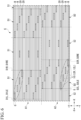
- An optical fiber ribbon 2 according to the present embodiment illustrated in FIG. 2 differs from the first embodiment in a positional relationship of regions D1, D2, S1, and S2.
- each first high-density region D1 and each second high-density region D2 do not overlap each other in a disposition direction Y.
- each first low-density region S 1 and two second low-density regions S2 closest to the first low-density region S 1 are disposed such that end portions thereof in a longitudinal direction X overlap in the disposition direction Y.
- each second low-density region S2 and two first low-density regions S 1 closest to the second low-density region S2 are disposed such that end portions thereof in the longitudinal direction X overlap in the disposition direction Y.
- the entire first high-density region D1 in the longitudinal direction X is adjacent to the second low-density region S2 in the disposition direction Y.
- the entire second high-density region D2 in the longitudinal direction X is adjacent to the first low-density region S1 in the disposition direction Y.
- the first low-density region S1 which is a portion with a lower rigidity than the first high-density region D1
- the second low-density region S2 which is a portion with a lower rigidity than the second high-density region D2 is reinforced by the first high-density region D1.
- each of a plurality of first high-density regions D1 and each of a plurality of second high-density regions D2 do not overlap with each other in the disposition direction Y.
- An optical fiber ribbon 3 according to the present embodiment illustrated in FIG. 3 differs from the first embodiment in a positional relationship of regions D1, D2, S1, and S2.
- each first low-density region S1 and each second low-density region S2 do not overlap with each other in a disposition direction Y.
- each first high-density region D1 and two second high-density regions D2 closest to the first high-density region D1 are disposed such that end portions thereof in a longitudinal direction X overlap in the disposition direction Y.
- each second high-density region D2 and two first high-density regions D1 closest to the second high-density region D2 are disposed such that end portions thereof in the longitudinal direction X overlap in the disposition direction Y.
- the first high-density region D1 or the second high-density region D2 is disposed at any position in the longitudinal direction X of the optical fiber ribbon 3. Therefore, a region with a high rigidity is disposed at any position in the longitudinal direction X of the optical fiber ribbon 3.
- each of a plurality of first low-density regions S1 and each of a plurality of second low-density regions S2 do not overlap with each other. With such a configuration, it is possible to enhance a rigidity of the optical fiber ribbon 3 more reliably.
- An optical fiber ribbon 4 according to the present embodiment illustrated in FIG. 4 differs from the first embodiment in a configuration of each of the high-density regions D1 and D2.
- connection parts 10 are disposed in each of a plurality (twelve in FIG. 4 ) of inter-fiber regions B included in each of the high-density regions D1 and D2.
- twenty four connection parts 10 are disposed in each of the high-density regions D1 and D2.
- three or more connection parts 10 may be disposed in each of the inter-fiber regions B.
- Different number of connection parts 10 may be disposed in each of the inter-fiber regions B.
- connection part 10 corresponding to a first right end connection part 11R, and the connection part 10 corresponding to a first left end connection part 11L are different from each other in each inter-fiber region B.
- optical fiber ribbon 4 it is possible to obtain the same operation and effect as those of the optical fiber ribbon 1 according to the first embodiment. Also, by increasing the number of the connection parts 10 disposed in each inter-fiber region B, it is possible to enhance a rigidity of the optical fiber ribbon 4 in each of the high-density regions D1 and D2. Thereby, it is possible to further enhance the rigidity of the optical fiber ribbon 4 as a whole.
- An optical fiber ribbon 5 according to the present embodiment illustrated in FIG. 5 differs from the first embodiment in a configuration of each of the high-density regions D1 and D2.
- connection part group G is disposed in each of the high-density regions D1 and D2. Also, within the connection part group G, a plurality (twelve in FIG. 5 ) of connection parts 10 are disposed to be continuous. Particularly, in the example of FIG. 5 , twelve connection parts are continuous in a curved shape. In other words, pitches P1 and P3 at which the connection parts 10 are disposed within the connection part group G included in each of the high-density regions D 1 and D2 are not constant.
- each first high-density region D1 a first right end edge D1RE and a first right straight line D1R do not overlap, and a first left end edge D1LE and a first left straight line D1L do not overlap.
- a second right end edge D2RE and a second right straight line D2R do not overlap, and a second left end edge D2LE and a second left straight line D2L do not overlap.
- the connection part 10 overlapping the first right straight line D1R does not overlap each of the plurality of second right straight lines D2R.
- connection part 10 overlapping the first left straight line D 1L does not overlap each of the plurality of second left straight lines D2L.
- connection part 10 overlapping the second right straight line D2R does not overlap each of the plurality of first right straight lines D 1R.
- connection part 10 overlapping the second left straight line D2L does not overlap each of the plurality of first left straight lines D 1L.
- the optical fiber ribbon 5 it is possible to obtain the same operation and effect as those of the optical fiber ribbon 1 according to the first embodiment. Also, since the plurality of connection parts 10 included in each of the high-density regions D 1 and D2 are continuous as one connection part group G, it is possible to dispose the plurality of connection parts 10 in the manner of a traversable figure (a figure written in one stroke) for each of the high-density regions D1 and D2. Thereby, for example, when a dispenser that discharges a resin to be the connection part 10 is moved at the time of manufacturing the optical fiber ribbon 5, a movement distance of the dispenser is reduced and a manufacturing efficiency is improved.
- An optical fiber ribbon 6 according to the present embodiment illustrated in FIG. 6 differs from the first embodiment in a configuration of each of the low-density regions S1 and S2.
- a connection part 10 is disposed in each of the low-density regions S1 and S2. Note that, also in the optical fiber ribbon 6 according to the present embodiment, a number density of the connection parts 10 in each first low-density region S1 is lower than a number density of the connection parts 10 in each first high-density region D1. Similarly, a number density of the connection parts 10 in each second low-density region S2 is lower than a number density of the connection parts 10 in each second high-density region D2.
- the optical fiber ribbon 6 it is possible to obtain the same operation and effect as those of the optical fiber ribbon 1 according to the first embodiment. Also, since the connection part 10 is also disposed in each of the low-density regions S1 and S2, it is possible to enhance a rigidity of the optical fiber ribbon 6 in each of the low-density regions S1 and S2. Thereby, it is possible to enhance the rigidity of the optical fiber ribbon 6 as a whole. Also, when the optical fiber ribbon 6 is fusion-spliced, it is possible to change a pitch between optical fibers 20 by peeling off the connection parts 10 included in the low-density regions S1 and S2. Since the number of connection parts 10 included in the low-density regions S1 and S2 is small, it is easy to peel them off.
- L9 ⁇ L6 and L9 ⁇ L8 have been satisfied for each of the plurality of first high-density regions D1, the plurality of first low-density regions S1, the plurality of second high-density regions D2, and the plurality of second low-density regions S2.
- L9 ⁇ L6 and L9 ⁇ L8 are satisfied for at least one of the first high-density region D1, first low-density region S1, second high-density region D2, and second low-density region S2
- a disposition pattern of the plurality of connection parts 10 included in each of the first high-density regions D1 may not be the same between the first high-density regions D1.
- a disposition pattern of the plurality of connection parts 10 included in each of the second high-density regions D2 may not be the same between the second high-density regions D2.
- connection part 10 in the longitudinal direction X and the disposition direction Y may not be the same between the connection parts 10.
- the plurality of connection parts 10 included in each of the high-density regions D1 and D2 may not form the connection part group G.
- the plurality of connection parts 10 may be randomly disposed in each of the high-density regions D1 and D2.
- the plurality of connection parts 10 may be randomly disposed in each of the low-density regions S 1 and S2.
- connection parts 10 may overlap the second right straight line D2R.
- a configuration in which all of the plurality of connection parts 10 do not overlap the second right straight line D2R has a larger offset between the first low-density region S1 and the second low-density region S2 in the longitudinal direction X, and this is suitable because it is possible to enhance the rigidity of the optical fiber ribbon 1 more reliably.
- connection parts 10 are included in the second high-density region and overlapping the second right straight line D2R.
- connection parts 10 being included in the second high-density region and overlapping the second left straight line D2L.
Landscapes
- Physics & Mathematics (AREA)
- General Physics & Mathematics (AREA)
- Optics & Photonics (AREA)
- Engineering & Computer Science (AREA)
- Plasma & Fusion (AREA)
- Mechanical Coupling Of Light Guides (AREA)
- Optical Fibers, Optical Fiber Cores, And Optical Fiber Bundles (AREA)
- Light Guides In General And Applications Therefor (AREA)
Abstract
Description
- The present invention relates to an optical fiber ribbon.
- Priority is claimed on
Japanese Patent Application No. 2021-115536 filed on July 13, 2021 -
Patent Document 1 discloses an optical fiber ribbon including a plurality of optical fibers disposed in a disposition direction perpendicular to a longitudinal direction, and a plurality of connection parts. The plurality of connection parts are formed between two optical fibers adjacent in the disposition direction, and connects the two optical fibers. - [Patent Document 1]
Japanese Unexamined Patent Application, First Publication No. 2021-43363 - The optical fiber ribbon of
Patent Document 1 has a plurality of high-density regions (connected regions) and a plurality of low-density regions (unconnected regions) that are alternately disposed in the longitudinal direction. At least two connection parts are disposed in each of the plurality of high-density regions. In each of the plurality of low-density regions, a connection part that fixes a disposition pitch between two adjacent optical fibers is not disposed. On the other hand, the optical fiber ribbon may be used as an optical fiber cable by being wrapped in, for example, a wrapping member, a sheath, or the like. In manufacturing such an optical fiber cable, a method in which an optical fiber ribbon and other constituent members (a wrapping member, a sheath, or the like) are joined together while the optical fiber ribbon is moved in the longitudinal direction is often employed. - Incidentally, a portion of the optical fiber ribbon in which the connection part is formed has a higher rigidity than the other portions. Therefore, a rigidity of the optical fiber ribbon in each low-density region is likely to be lower than a rigidity of the optical fiber ribbon in each high-density region. For example, in the optical fiber ribbon of
Patent Document 1, the high-density regions with a high rigidity and the low-density regions with a low rigidity are alternately disposed in the longitudinal direction. When the optical fiber ribbon is moved at the time of manufacturing optical fiber cables, there is a likelihood that the optical fiber ribbon will become corrugated or twisted in a portion in which the rigidity is low. Such corrugation or undulation of the optical fiber ribbon may hinder smooth manufacture of optical fiber cables. - The present invention has been made in consideration of such circumstances, and an objective of the present invention is to provide an optical fiber ribbon with enhanced rigidity.
- In order to solve the above-described problems, an optical fiber ribbon according to one aspect of the present invention includes five or more optical fibers disposed in a disposition direction perpendicular to a longitudinal direction, and a plurality of connection parts formed between two of the optical fibers adjacent in the disposition direction to connect the two optical fibers, in which the plurality of connection parts are disposed intermittently in the longitudinal direction and the disposition direction, and the optical fiber ribbon includes at least one first high-density region and at least one first low-density region disposed at different positions in the longitudinal direction, and at least one second high-density region and at least one second low-density region disposed at different positions in the longitudinal direction, in which at least two connection parts having different positions from each other in the longitudinal direction and the disposition direction among the plurality of connection parts are disposed in the first high-density region, at least two connection parts having different positions from each other in the longitudinal direction and the disposition direction among the plurality of connection parts are disposed in the second high-density region, a number density of the connection parts in the first low-density region is lower than a number density of the connection parts in the first high-density region, a number density of the connection parts in the second low-density region is lower than a number density of the connection parts in the second high-density region, and a dimension L9 in the longitudinal direction of a portion in which the first low-density region and the second low-density region overlap in the disposition direction is smaller than a dimension L6 of the first low-density region in the longitudinal direction and a dimension L8 of the second low-density region in the longitudinal direction.
- According to the above-described aspect of the present invention, it is possible to provide an optical fiber ribbon with enhanced rigidity.
-
-
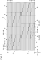
FIG. 1 is a plan view illustrating an optical fiber ribbon according to a first embodiment of the present invention. -
FIG. 2 is a plan view illustrating an optical fiber ribbon according to a second embodiment of the present invention. -
FIG. 3 is a plan view illustrating an optical fiber ribbon according to a third embodiment of the present invention. -
FIG. 4 is a plan view illustrating an optical fiber ribbon according to a fourth embodiment of the present invention. -
FIG. 5 is a plan view illustrating an optical fiber ribbon according to a fifth embodiment of the present invention. -
FIG. 6 is a plan view illustrating an optical fiber ribbon according to a sixth embodiment of the present invention. - Hereinafter, an optical fiber ribbon according to a first embodiment will be described on the basis of the drawings.
- As illustrated in
FIG. 1 , anoptical fiber ribbon 1 includes a plurality ofoptical fibers 20. The plurality ofoptical fibers 20 are disposed in a direction perpendicular to a longitudinal direction of eachoptical fiber 20. Theoptical fiber ribbon 1 further includes a plurality ofconnection parts 10 connecting twooptical fibers 20 adjacent to each other among the plurality ofoptical fibers 20. - In the example of
FIG. 1 , the number of theoptical fibers 20 included in theoptical fiber ribbon 1 is twenty five. However, the number of theoptical fibers 20 may be changed as appropriate, and the number of theoptical fibers 20 is not limited as long as it is five or more. - Here, in the present embodiment, a longitudinal direction of the optical fiber ribbon is simply referred to as a longitudinal direction X. One direction in the longitudinal direction X is referred to as a +X direction or a rightward direction. A direction opposite to the +X direction is referred to as a -X direction or a leftward direction. A direction in which the plurality of
optical fibers 20 are disposed is referred to as a disposition direction Y. The disposition direction Y is orthogonal to the longitudinal direction X. One direction in the disposition direction Y is referred to as a +Y direction or an upward direction. A direction opposite to the +Y direction is referred to as a -Y direction or a downward direction. A direction orthogonal to the longitudinal direction X and the disposition direction Y is referred to as a surface normal direction Z. - The
optical fibers 20 each have a waveguide and a coating part (not illustrated). The waveguide is formed of, for example, glass. The waveguide has a core and a cladding. The coating part is formed of a resin or the like and covers a glass part. As a specific material for the coating part, for example, a UV curable resin may be given. - Each
optical fiber 20 extends in the longitudinal direction X. The plurality ofoptical fibers 20 are disposed in the disposition direction Y A gap may be provided between twooptical fibers 20 adjacent in the disposition direction Y, or the twooptical fibers 20 may be in contact with each other. In theoptical fiber ribbon 1 according to the present embodiment, the plurality ofoptical fibers 20 are disposed at substantially constant intervals (disposition pitch P5) in the disposition direction Y Hereinafter, a gap or a contact surface between twooptical fibers 20 adjacent in the disposition direction Y will be referred to as an inter-fiber region B. In the example ofFIG. 1 , twenty fiveoptical fibers 20 and twenty four inter-fiber regions B are alternately disposed in the disposition direction Y. - The plurality of
connection parts 10 are each formed in the inter-fiber region B. The plurality ofconnection parts 10 are disposed intermittently in the longitudinal direction X and the disposition direction Y. In the present specification, the plurality ofconnection parts 10 being "intermittently disposed" includes both cases in which the intervals between theconnection parts 10 are constant and the intervals between theconnection parts 10 are not constant. Each of theconnection parts 10 connects twooptical fibers 20 adjacent to the inter-fiber region B in which theconnection part 10 is disposed. More specifically, eachconnection part 10 connects coating parts of twooptical fibers 20 adjacent to the inter-fiber region B in which theconnection part 10 is disposed. That is, in theoptical fiber ribbon 1 according to the present embodiment, twooptical fibers 20 adjacent in the disposition direction Y are intermittently connected to each other in the longitudinal direction X by the plurality ofconnection parts 10. Theoptical fiber ribbon 1 is also referred to as an intermittently-fixedoptical fiber ribbon 1. As theconnection part 10, any material capable of connecting coating parts of adjacentoptical fibers 20 may be used. For example, a UV curable resin may be used as theconnection part 10. - The
optical fiber ribbon 1 according to the present embodiment includes a plurality of first high-density regions D 1, a plurality of first low-density regions S1, a plurality of second high-density regions D2, and a plurality of second low-density regions S2. The plurality of first high-density regions D 1 and the plurality of first low-density regions S1 are alternately disposed in the longitudinal direction X. The plurality of second high-density regions D2 and the plurality of second low-density regions S2 are alternately disposed in the longitudinal direction X. In the present embodiment, the first high-density regions D1 and the second high-density regions D2 are disposed at different positions in the disposition direction Y. - In the present embodiment, a dimension L1 of each of the first high-density regions D1 in the disposition direction Y and a dimension L2 of each of the first low-density regions S1 in the disposition direction Y are substantially equal to each other. A dimension L3 of each of the second high-density regions D2 in the disposition direction Y and a dimension L4 of each of the second low-density regions S2 in the disposition direction Y are substantially equal to each other. Also, the dimension L1 and the dimension L3 may be substantially equal to each other. In the present embodiment, a dimension of each first high-density region D1 in the longitudinal direction X is substantially constant at a dimension L5. A dimension of each first low-density region S1 in the longitudinal direction Xis substantially constant at a dimension L6. A dimension of each second high-density region D2 in the longitudinal direction X is substantially constant at a dimension L7. A dimension of each second low-density region S2 in the longitudinal direction X is substantially constant at a dimension L8. However, each of the dimensions L5 to L8 may not be substantially constant. Also, the dimension L5 and the dimension L7 may be substantially equal to each other. The dimension L6 and the dimension L8 may be substantially equal to each other. In the present embodiment, the regions D1, D2, S1, and S2 each include thirteen
optical fibers 20 and twleve inter-fiber regions B. - A region in which the plurality of first high-
density regions D 1 and the plurality of first low-density regions S1 are combined is referred to as a first region A1. A region in which the plurality of second high-density regions D2 and the plurality of second low-density regions S2 are combined is referred to as a second region A2. In the present embodiment, the first region A1 and the second region A2 are adjacent to each other in the disposition direction Y. Note that, the first region A1 and the second region A2 may not be adjacent to each other in the disposition direction Y. - In the present embodiment, each of the plurality of first high-density regions D1, each of the plurality of first low-density regions S1, each of the plurality of second high-density regions D2, and each of the plurality of second low-density regions S2 are formed in a substantially rectangular shape. Hereinafter, a right end edge of each first high-density region D1 may be referred to as a first right end edge D1RE, and a left end edge of each first high-density region D1 may be referred to as a first left end edge D1LE. Similarly, a right end edge of each second high-density region D2 may be referred to as a second right end edge D2RE, and a left end edge of each second high-density region D2 may be referred to as a second left end edge D2LE. In the present embodiment, the end edges D1RE, D1LE, D2RE, and D2LE are each a line segment parallel to the disposition direction Y. At least one
connection part 10 is disposed to be in contact with each of the end edges D1RE, D1LE, D2RE, and D2LE. - In the present embodiment, the first right end edge D1RE of each first high-density region D1 is also a left end edge of the first low-density region S1 that is adjacent to the right side of the first high-
density region D 1. Similarly, the first left end edge D1LE of each first high-density region D1 is also a right end edge of the first low-density region S1 that is adjacent to the left side of the first high-density region D1. That is, each first high-density region D1 and each first low-density region S1 are defined by each first right end edge D1RE and each first left end edge D1LE. In the present embodiment, the second right end edge D2RE of each second high-density region D2 is also a left end edge of the second low-density region S2 that is adjacent to the right side of the second high-density region D2. Similarly, the second left end edge D2LE of each second high-density region D2 is also a right end edge of the second low-density region S2 that is adjacent to the left side of the second high-density region D2. That is, each second high-density region D2 and each second low-density region S2 are defined by each second right end edge D2RE and each second left end edge D2LE. - Hereinafter, configurations of each of the first high-
density regions D 1 and each of the first low-density regions S1 will be described. - In each first high-density region D1, among the plurality of
connection parts 10, at least twoconnection parts 10 having different positions from each other in the longitudinal direction X and the disposition direction Y are disposed. In the example ofFIG. 1 , twelveconnection parts 10 are disposed in each first high-density region D1. In the example ofFIG. 1 , a disposition pattern of the twelveconnection parts 10 included in each first high-density region D1 is substantially the same between the first high-density regions D1. More specifically, three connection part groups G are disposed in each first high-density region D1, and the three connection part groups G are disposed in the disposition direction Y. Within each of the connection part groups G, fourconnection parts 10 are disposed to be continuous in a straight line. In other words, within each first high-density region D1, the twelveconnection parts 10 are disposed periodically in the disposition direction Y with four connection parts 10 (connection part group G) as one unit. Note that, the number ofconnection parts 10 included in each connection part group G may be changed as appropriate, and the number of theconnection parts 10 is not limited as long as it is two or more. Within each connection part group G, the plurality of connection parts may be disposed to be continuous in a curved shape. Also, the number of the connection part groups G included in each first high-density region D1 may be changed as appropriate. The number of theconnection parts 10 included in each first high-density region D1 may be changed as appropriate, and the number of theconnection parts 10 is not limited as long as it is two or more. - In the example of
FIG. 1 , within each connection part group G, fourconnection parts 10 are disposed at a substantially constant pitch P1 in the longitudinal direction X. Also, the fourconnection parts 10 are disposed at substantially constant intervals P2 in the longitudinal direction X. Note that, the fourconnection parts 10 may be disposed without the intervals P2 in the longitudinal direction X. That is, theconnection parts 10 may overlap each other in the disposition direction Y. Also, within each connection part group G, an inter-fiber region B in which acertain connection part 10 is disposed and an inter-fiber region B in which aconnection part 10 closest to the above-describedconnection part 10 is disposed are adjacent in the disposition direction Y. Here, in each connection part group G, theconnection part 10 positioned on an uppermost side among the fourconnection parts 10 included in the connection part group G is referred to as an upper end connection part. In each connection part group G, theconnection part 10 positioned on a lowermost side among the fourconnection parts 10 included in the connection part group G is referred to as a lower end connection part. In the present embodiment, the three connection part groups G are adjacent in the disposition direction Y. For example, the inter-fiber region B in which the upper end connection part of the connection part group G positioned at a center among the three connection part groups G is disposed is adjacent to the inter-fiber region B in which the lower end connection part of the connection part group G positioned on an upper side among the three connection part groups G is disposed. Similarly, the inter-fiber region B in which the lower end connection part of the connection part group G positioned at a center among the three connection part groups G is disposed is adjacent to the inter-fiber region B in which the upper end connection part of the connection part group G positioned on a lower side among the three connection part groups G is disposed. Since the connection part groups G are adjacent in the disposition direction Y, oneconnection part 10 is disposed in each inter-fiber region B included in each first high-density region D1. Note that, the connection part groups G may not be adjacent in the disposition direction Y. - In the example of
FIG. 1 , threeconnection parts 10 each positioned on a rightmost side among the fourconnection parts 10 included in each connection part group G of each first high-density region D1 are disposed at substantially the same position as each other in the longitudinal direction X. These threeconnection parts 10 are in contact with the first right end edge D1RE. Similarly, threeconnection parts 10 each positioned on a leftmost side among the fourconnection parts 10 included in each connection part group G are disposed at substantially the same position as each other in the longitudinal direction X. These threeconnection parts 10 are in contact with the first left end edge D1LE. - In the example of
FIG. 1 , the connection part group G similar to that of the first high-density region D1 is disposed in each second high-density region D2 (details will be described later). The connection part group G is included in any one of the plurality of first high-density regions D1 and the plurality of second high-density regions D2. Note that, theconnection part 10 that does not belong to the connection part group G may be included in the first high-density region D1 and the second high-density region D2. - A number density of the
connection parts 10 in each first low-density region S1 is lower than a number density of theconnection parts 10 in each first high-density region D1. Similarly, a number density of theconnection parts 10 in each second low-density region S2 is lower than a number density of theconnection parts 10 in each second high-density region D2. The "number density of theconnection parts 10 in the first low-density region S1" is a value obtained by dividing the number of theconnection parts 10 included in the first low-density region S1 by an area of the first low-density region S1. The "number density of theconnection parts 10 in the first high-density region D1" is a value obtained by dividing the number of theconnection parts 10 included in the first high-density region D 1 by an area of the first high-density region D 1. The number densities of the second low-density region S2 and the second high-density region D2 are similarly defined. In the example ofFIG. 1 , theconnection part 10 is not included in each of the low-density regions S1 and S2. That is, the number densities of theconnection parts 10 in the low-density regions S1 and S2 are zero. However, theconnection part 10 may be included in the low-density regions S1 and S2. - Hereinafter, configurations of each of the second high-density regions D2 and each of the second low-density regions S2 will be described below. Note that, in the present embodiment, the configuration of each of the second high-density regions D2 is substantially the same as the configuration of each of the first high-density regions D1. Similarly, the configuration of each of the second low-density regions S2 is substantially the same as the configuration of each of the first low-density regions S1.
- In each second high-density region D2, among the plurality of
connection parts 10, at least twoconnection parts 10 having different positions from each other in the longitudinal direction X and the disposition direction Y are disposed. In the example ofFIG. 1 , twelveconnection parts 10 are disposed in each second high-density region D2. In the example ofFIG. 1 , a disposition pattern of the twelveconnection parts 10 included in each second high-density region D2 is substantially the same between the second high-density regions D2. More specifically, three connection part groups G are disposed in each second high-density region D2, and the three connection part groups G are disposed in the disposition direction Y. Within each of the connection part groups G, fourconnection parts 10 are disposed to be continuous in a straight line. In other words, within each second high-density region D2, the twelveconnection parts 10 are disposed periodically in the disposition direction Y with four connection parts 10 (connection part group G) as one unit. Note that, the number ofconnection parts 10 included in each connection part group G may be changed as appropriate, and the number of theconnection parts 10 is not limited as long as it is two or more. Within each connection part group G, a plurality of connection parts may be disposed to be continuous in a curved shape. Also, the number of the connection part groups G included in each second high-density region D2 may be changed as appropriate. The number of theconnection parts 10 included in each second high-density region D2 may be changed as appropriate, and the number of theconnection parts 10 is not limited as long as it is two or more. - In the example of
FIG. 1 , within each connection part group G, fourconnection parts 10 are disposed at a substantially constant pitch P3 in the longitudinal direction X. Also, the fourconnection parts 10 are disposed at substantially constant intervals P4 in the longitudinal direction X. Note that, the fourconnection parts 10 may be disposed without the intervals P4 in the longitudinal direction X. That is, theconnection parts 10 may overlap each other in the disposition direction Y. Also, within each connection part group G, an inter-fiber region B in which acertain connection part 10 is disposed and an inter-fiber region B in which aconnection part 10 adjacent to the above-describedconnection part 10 is disposed are adjacent in the disposition direction Y. The three connection part groups G are adjacent in the disposition direction Y. For example, the inter-fiber region B in which the upper end connection part of the connection part group G positioned at a center among the three connection part groups G is disposed is adjacent to the inter-fiber region B in which the lower end connection part of the connection part group G positioned on an upper side among the three connection part groups G is disposed. Similarly, the inter-fiber region B in which the lower end connection part of the connection part group G positioned at a center among the three connection part groups G is disposed is adjacent to the inter-fiber region B in which the upper end connection part of the connection part group G positioned on a lower side among the three connection part groups G is disposed. Since the connection part groups G are adjacent in the disposition direction Y, oneconnection part 10 is disposed in each inter-fiber region B included in each second high-density region D2. Note that, the connection part groups G may not be adjacent in the disposition direction Y. - In the example of
FIG. 1 , threeconnection parts 10 each positioned on a rightmost side among the fourconnection parts 10 included in each connection part group G of each second high-density region D2 are disposed at substantially the same position as each other in the longitudinal direction X. These threeconnection parts 10 are in contact with the second right end edge D2RE. Similarly, threeconnection parts 10 each positioned on a leftmost side among the fourconnection parts 10 included in each connection part group G are disposed at substantially the same position as each other in the longitudinal direction X. These threeconnection parts 10 are in contact with the second left end edge D2LE. - Hereinafter, a positional relationship between each of the first high-density regions D1, each of the first low-density regions S1, each of the second high-density regions D2, and each of the second low-density regions S2 will be described.
- Each of the first low-density regions S1 according to the present embodiment has, at least one second low-density region S2 that overlaps therewith in the disposition direction Y. In other words, each first low-density region S1 and each second low-density region S2 overlap each other in the disposition direction Y. A dimension of each overlapping portion in the longitudinal direction X is substantially constant at a dimension L9.
- In the present embodiment, the dimension L9 is smaller than the dimension L6 of each first low-
density region S 1 in the longitudinal direction X and the dimension L8 of each second low-density region S2 in the longitudinal direction X. That is, L9 < L6 and L9 < L8 are satisfied. Also, the dimension L9 is smaller than the dimension L5 of each first high-density region D1 in the longitudinal direction X and the dimension L7 of each second high-density region D2 in the longitudinal direction X. That is, L9 < L5 and L9 < L7 are satisfied. That is, the dimension L9 in the longitudinal direction X of a portion of theoptical fiber ribbon 1 having a lowest rigidity in the longitudinal direction X (that is, a portion in which the first low-density region S 1 and the second low-density region S2 overlap in the disposition direction Y) is smaller than the dimensions L5 to L8. Thereby, it is possible to reduce an area of the portion of theoptical fiber ribbon 1 having the lowest rigidity in the longitudinal direction X (that is, the portion of the dimension L9), and enhance the rigidity of theoptical fiber ribbon 1 as a whole. - Hereinafter, the
connection part 10 positioned on a rightmost side in each inter-fiber region B included in each first high-density region D1 is referred to as a first rightend connection part 11R. Theconnection part 10 positioned on a leftmost side in each inter-fiber region B included in each first high-density region D1 is referred to as a first leftend connection part 11L. Theconnection part 10 positioned on a rightmost side in each inter-fiber region B included in each second high-density region D2 is referred to as a second rightend connection part 12R. Theconnection part 10 positioned on a leftmost side in each inter-fiber region B included in each second high-density region D2 is referred to as a second leftend connection part 12L. Note that, in the example ofFIG. 1 , for all the inter-fiber regions B included in each inter-fiber regions B included in each first high-density region D1, there is only oneconnection part 10 disposed in each inter-fiber region B. Therefore, each of all theconnection parts 10 included in each first high-density region D1 corresponds to both the first rightend connection part 11R and the first leftend connection part 11L. Similarly, in the example ofFIG. 1 , each of all theconnection parts 10 included in each second high-density region D2 corresponds to both the second rightend connection part 12R and the second leftend connection part 12L. - In each first high-
density region D 1, a straight line connecting right ends of two first rightend connection parts 11R positioned on a rightmost side is referred to as a first right straight line D 1R. Note that, if there are a plurality of positions (points) corresponding to the right ends in each first rightend connection part 11R, the first right straight line D1R is defined to connect a midpoint between two points positioned at both ends of the plurality of positions in the disposition direction Y. The same applies to the first left straight line D1L, the second right straight line D2R, and the second left straight line D2L defined below. In each first high-density region D1, a straight line connecting left ends of two first leftend connection parts 11L positioned on a leftmost side is referred to as the first left straight line D1L. In each second high-density region D2, a straight line connecting right ends of two second rightend connection parts 12R positioned on a rightmost side is referred to as the second right straight line D2R. In each second high-density region D2, a straight line connecting left ends of two second leftend connection parts 12L positioned on a leftmost side is referred to as the second left straight line D2L. In the example ofFIG. 1 , each first right straight line D1R overlaps each first right end edge D1RE, and each first left straight line D1L overlaps each first left end edge D1LE. Similarly, each second right straight line D2R overlaps each second right end edge D2RE. - In the present embodiment, the
connection parts 10 overlapping the first right straight line D1R among the plurality ofconnection parts 10 included in each first high-density region D1 (in the example ofFIG. 1 , the threeconnection parts 10 in contact with the first right end edge D1RE) all do not overlap each of a plurality of second right straight lines D2R. Similarly, theconnection parts 10 overlapping the first left straight line D1L among the plurality ofconnection parts 10 included in each first high-density region D1 (in the example ofFIG. 1 , the threeconnection parts 10 in contact with the first left end edge D 1LE) all do not overlap each of a plurality of second left straight lines D2L. Theconnection parts 10 overlapping the second right straight line D2R among the plurality ofconnection parts 10 included in each second high-density region D2 (in the example ofFIG. 1 , the threeconnection parts 10 in contact with the second right end edge D2RE) all do not overlap each of a plurality of first right straight lines D1R. Theconnection parts 10 overlapping the second left straight line D2L among the plurality ofconnection parts 10 included in each second high-density region D2 (in the example ofFIG. 1 , the threeconnection parts 10 in contact with the second left end edge D2LE) all do not overlap each of a plurality of first left straight lines D 1L. - Next, an operation of the
optical fiber ribbon 1 configured as above will be described. - The
optical fiber ribbon 1 according to the present embodiment includes the plurality of first high-density regions D 1 and the plurality of second high-density regions D2 in which a large number ofconnection parts 10 are disposed, and the plurality of first low-density regions S1 and the plurality of second low-density regions S2 in which the number ofdisposed connection parts 10 are small (particularly, in the example ofFIG. 1 , noconnection part 10 is disposed). Here, in each first high-density regions D1 and each second high-density regions D2, the plurality ofoptical fibers 20 are connected to each other and are integrated. Theconnection part 10 also has a role of fixing the disposition pitch P5 between two adjacentoptical fibers 20. Therefore, it is possible to stabilize the disposition pitch P5in each first high-density region D1 and each second high-density region D2. - Incidentally, when an optical fiber ribbon is fusion-spliced to another optical fiber ribbon, a fusion splicer is generally used. A plurality of grooves extending in the longitudinal direction X are formed in the fusion splicer. Inside the fusion splicer, each of the
optical fibers 20 included in the optical fiber ribbon is inserted through each of the plurality of grooves described above for positioning. Here, the disposition pitch P5 is fixed by theconnection part 10. Therefore, when a fusion work is performed on a certain optical fiber ribbon, conventionally, a fusion splicer having grooves disposed at the disposition pitch P5 of the optical fibers in the optical fiber ribbon has been used. - However, in recent years, research and development has been actively conducted to reduce a diameter of the
optical fiber 20, and accordingly, the disposition pitch P5 of theoptical fibers 20 has also been reduced. Therefore, in a case of trying to fusion-splice optical fiber ribbons manufactured at different times, since the disposition pitches P5 of the two optical fiber ribbons are different from each other, there has been a problem that it is difficult to fusion-splice the two optical fiber ribbons using a fusion splicer. - On the other hand, the
optical fiber ribbon 1 according to the present embodiment has the plurality of first low-density regions S 1 and the plurality of second low-density regions S2. In each of the first low-density regions S 1 and each of the second low-density regions S2, theconnection parts 10 for fixing the disposition pitch P5 between two adjacentoptical fibers 20 are not disposed or are few. Therefore, it is possible for the user to change the disposition pitch P5 by pulling or compressing theoptical fiber ribbon 1 in the disposition direction Y in the first low-density region S 1 or the second low-density region S2. Thereby, when theoptical fiber ribbon 1 is fusion-spliced, it is possible to use a fusion splicer having the disposition pitch P5 different from that of theoptical fiber ribbon 1. Also, it is possible to fusion-splice theoptical fiber ribbon 1 to an optical fiber ribbon having the disposition pitch P5 different from that of theoptical fiber ribbon 1. - On the other hand, the
optical fiber ribbon 1 may be used as an optical fiber cable by being wrapped in, for example, a wrapping member, a sheath, or the like. In manufacturing such an optical fiber cable, a method in which theoptical fiber ribbon 1 and other constituent member (a wrapping member, a sheath, or the like) are joined together while theoptical fiber ribbon 1 is moved in the longitudinal direction X is often employed. - Here, a portion in which the
connection part 10 is formed between theoptical fibers 20 has a higher rigidity than a portion in which theconnection part 10 is not provided. Therefore, the rigidity of theoptical fiber ribbon 1 in each of the low-density regions S 1 and S2 is likely to be lower than the rigidity of theoptical fiber ribbon 1 in each of the high-density regions D1 and D2. For example, in a case of an optical fiber ribbon in which a plurality of high-density regions and a plurality of low-density regions are simply disposed alternately in the longitudinal direction (in a case of an optical fiber ribbon having only one of the first region A1 and the second region A2 in the present embodiment), there are portions in which the rigidity is extremely low (low-density regions) in the longitudinal direction of the optical fiber ribbon. In such a case of the optical fiber ribbon having portions with extremely low rigidity, when the optical fiber ribbon is moved, there is a likelihood that the optical fiber ribbon will become corrugated or twisted in the portions in which the rigidity is extremely low. Such corrugation or undulation of the optical fiber ribbon has hindered smooth manufacture of optical fiber cables. - In contrast, the
optical fiber ribbon 1 according to the present embodiment has both the first region A1 and the second region A2, and furthermore, the first region A1 and the second region A2 are offset from each other in the longitudinal direction X. More specifically, each of the first high-density regions D 1 and each of the second high-density regions D2 are disposed to be offset from each other in the longitudinal direction X, and each of the first low-density regions S 1 and each of the second low-density regions S2 are disposed to be offset from each other in the longitudinal direction X. Thereby, the dimension L9 in the longitudinal direction X of the portion of theoptical fiber ribbon 1 in which the rigidity is the lowest in the longitudinal direction X (that is, the portion in which the first low-density region S 1 and the second low-density region S2 overlap in the disposition direction Y) becomes smaller. That is, it is possible to make the dimension L9 in the longitudinal direction X of the portion having a particularly low rigidity in theoptical fiber ribbon 1 small. Therefore, it is possible to enhance the rigidity of theoptical fiber ribbon 1 as a whole, and suppress corrugation or twisting of theoptical fiber ribbon 1 when theoptical fiber ribbon 1 is moved. - As described above, the optical fiber ribbon 1 according to the present embodiment includes five or more optical fibers 20 disposed in the disposition direction Y, and the plurality of connection parts 10 formed between two optical fibers 20 adjacent in the disposition direction Y to connect the two optical fibers 20, in which the plurality of connection parts 10 are disposed intermittently in the longitudinal direction X and the disposition direction Y, and the optical fiber ribbon 1 includes the plurality of first high-density regions D 1 and the plurality of first low-density regions S 1 alternately disposed in the longitudinal direction X, and the plurality of second high-density regions D2 and the plurality of second low-density regions S2 alternately disposed in the longitudinal direction X, in which at least two connection parts 10 having different positions from each other in the longitudinal direction X and the disposition direction Y among the plurality of connection parts 10 are disposed in each of the plurality of first high-density regions D1, at least two connection parts 10 having different positions from each other in the longitudinal direction X and the disposition direction Y among the plurality of connection parts 10 are disposed in each of the plurality of second high-density regions D2, a number density of the connection parts 10 in each of the plurality of first low-density regions S1 is lower than a number density of the connection parts 10 in each of the plurality of first high-density regions D 1, a number density of the connection parts 10 in each of the plurality of second low-density regions S2 is lower than a number density of the connection parts 10 in each of the plurality of second high-density regions D2, and the dimension L9 in the longitudinal direction X of each portion in which each of the plurality of first low-density regions S 1 and each of the plurality of second low-density regions S2 overlap in the disposition direction Y is smaller than the dimension L6 of each of the plurality of first low-density regions S 1 in the longitudinal direction X and the dimension L8 of each of the plurality of second low-density regions S2 in the longitudinal direction X.
- With this configuration, the first low-
density region S 1 having a lower rigidity than the first high-density region D1, and the second low-density region S2 having a lower rigidity than the second high-density region D2 are disposed to be offset in the longitudinal direction X. Thereby, the dimension L9 in the longitudinal direction X of the portion having the lowest rigidity in the longitudinal direction X of the optical fiber ribbon 1 (that is, the portion in which the first low-density region S1 and the second low-density region S2 overlap in the disposition direction Y) becomes smaller than, for example, a case in which the first low-density region S 1 and the second low-density region S2 are not offset in the longitudinal direction X. Therefore, it is possible to enhance the rigidity of theoptical fiber ribbon 1 as a whole, and suppress corrugation or twisting of theoptical fiber ribbon 1 when theoptical fiber ribbon 1 is moved. - Also, the
connection part 10 overlapping the first right straight line D1R among the plurality ofconnection parts 10 included in each of the plurality of first high-density regions D1 does not overlap each of the plurality of second right straight lines D2R, theconnection part 10 overlapping the first left straight line D1L among the plurality ofconnection parts 10 included in each of the plurality of first high-density regions D 1 does not overlap each of the plurality of second left straight lines D2L, theconnection part 10 overlapping the second right straight line D2R among the plurality ofconnection parts 10 included in each of the plurality of second high-density regions D2 does not overlap each of the plurality of first right straight line D 1R, and theconnection part 10 overlapping the second left straight line D2L among the plurality ofconnection parts 10 included in each of the plurality of second high-density regions D2 does not overlap each of the plurality of first left straight lines D 1L. With this configuration, an offset between the first low-density region S1 and the second low-density region S2 in the longitudinal direction X is further increased. In other words, the dimension L9 becomes even smaller. Thereby, it is possible to further enhance the rigidity of theoptical fiber ribbon 1. - Also, the dimension L9 in the longitudinal direction X of each portion in which each of the plurality of first low-
density regions S 1 and each of the plurality of second low-density regions S2 overlap in the disposition direction Y is smaller than the dimension L5 of each of the plurality of first high-density regions D1 in the longitudinal direction X and the dimension L7 of each of the plurality of second high-density regions D2 in the longitudinal direction X. With this configuration, each of the high-density regions D1 and D2 having a high rigidity has a larger dimension in the longitudinal direction X than the portion of theoptical fiber ribbon 1 having a particularly low rigidity in the longitudinal direction X. Therefore, the rigidity of theoptical fiber ribbon 1 is further enhanced as a whole. - Also, at least one
connection part 10 is disposed in each of the plurality of inter-fiber regions B included in each of the plurality of first high-density regions D1, and at least oneconnection part 10 is disposed in each of the plurality of inter-fiber regions B included in each of the plurality of second high-density regions D2. With this configuration, separation of theoptical fiber ribbon 1 in the disposition direction Y is suppressed in the first high-density region D1 or the second high-density region D2. - Also, at least one
connection part 10 is disposed in each of the plurality of first right end edge D1RE and each of the plurality of first left end edge D 1LE, and at least oneconnection part 10 is disposed in each of the plurality of second right end edge D2RE and each of the plurality of second left end edge D2LE. Thereby, it is possible to enhance the rigidity of each first high-density region D1, compared to, for example, a case in which theconnection part 10 is not disposed at each first right end edge D1RE and each first left end edge D1LE. Similarly, it is possible to enhance the rigidity of each second high-density region D2, compared to, for example, a case in which theconnection part 10 is not disposed at each second right end edge D2RE and each second left end edge D2LE. Therefore, it is possible to enhance the rigidity of theoptical fiber ribbon 1 as a whole. - Also, the first region A1, which is a region in which the plurality of first high-
density regions D 1 and the plurality of first low-density regions S 1 are combined, and the second region A2, which is a region in which the plurality of second high-density regions D2 and the plurality of second low-density regions S2 are combined, are adjacent in the disposition direction Y. With this configuration, theoptical fiber ribbon 1 being bent with the longitudinal direction X as an axis is suppressed, compared to, for example, a case in which the first region A1 and the second region A2 are not adjacent in the disposition direction Y. - Also, in the disposition direction Y, the dimension L1 of each of the plurality of first high-
density regions D 1 and the dimension L2 of each of the plurality of first low-density regions S 1 are equal to each other, and the dimension L3 of each of the plurality of second high-density regions D2 and the dimension L4 of each of the plurality of second low-density regions S2 are equal to each other. Thereby, it is possible to enhance the rigidity of theoptical fiber ribbon 1, compared to, for example, a case in which the dimension L1 is smaller than the dimension L2, and the dimension L3 is smaller than the dimension L4. - Next, a second embodiment of the present invention will be described, but a basic configuration is the same as that of the first embodiment. Therefore, components which are the same are denoted by the same reference signs, description thereof will be omitted, and only different points will be described.
- An
optical fiber ribbon 2 according to the present embodiment illustrated inFIG. 2 differs from the first embodiment in a positional relationship of regions D1, D2, S1, and S2. - As illustrated in
FIG. 2 , in the present embodiment, each first high-density region D1 and each second high-density region D2 do not overlap each other in a disposition direction Y. Also, each first low-density region S 1 and two second low-density regions S2 closest to the first low-density region S 1 are disposed such that end portions thereof in a longitudinal direction X overlap in the disposition direction Y. Similarly, each second low-density region S2 and two first low-density regions S 1 closest to the second low-density region S2 are disposed such that end portions thereof in the longitudinal direction X overlap in the disposition direction Y. - In this case, the entire first high-density region D1 in the longitudinal direction X is adjacent to the second low-density region S2 in the disposition direction Y. Similarly, the entire second high-density region D2 in the longitudinal direction X is adjacent to the first low-density region S1 in the disposition direction Y. According to such a disposition, the first low-density region S1, which is a portion with a lower rigidity than the first high-density region D1, is reinforced by the second high-density region D2. Similarly, the second low-density region S2, which is a portion with a lower rigidity than the second high-density region D2, is reinforced by the first high-density region D1.
- As described above, in the
optical fiber ribbon 2 according to the present embodiment, each of a plurality of first high-density regions D1 and each of a plurality of second high-density regions D2 do not overlap with each other in the disposition direction Y. With such a configuration, it is possible to reinforce the low-density regions S1 and S2 with a lower rigidity by the high-density regions D1 and D2 with a higher rigidity. Therefore, it is possible to enhance the rigidity of theoptical fiber ribbon 2 as a whole. - Next, a third embodiment of the present invention will be described, but a basic configuration is the same as that of the first embodiment. Therefore, components which are the same are denoted by the same reference signs, description thereof will be omitted, and only different points will be described.
- An
optical fiber ribbon 3 according to the present embodiment illustrated inFIG. 3 differs from the first embodiment in a positional relationship of regions D1, D2, S1, and S2. - As illustrated in
FIG. 3 , in the present embodiment, each first low-density region S1 and each second low-density region S2 do not overlap with each other in a disposition direction Y. Also, each first high-density region D1 and two second high-density regions D2 closest to the first high-density region D1 are disposed such that end portions thereof in a longitudinal direction X overlap in the disposition direction Y. Similarly, each second high-density region D2 and two first high-density regions D1 closest to the second high-density region D2 are disposed such that end portions thereof in the longitudinal direction X overlap in the disposition direction Y. - In this case, the first high-density region D1 or the second high-density region D2 is disposed at any position in the longitudinal direction X of the
optical fiber ribbon 3. Therefore, a region with a high rigidity is disposed at any position in the longitudinal direction X of theoptical fiber ribbon 3. - As described above, in the
optical fiber ribbon 3 according to the present embodiment, each of a plurality of first low-density regions S1 and each of a plurality of second low-density regions S2 do not overlap with each other. With such a configuration, it is possible to enhance a rigidity of theoptical fiber ribbon 3 more reliably. - Next, a fourth embodiment of the present invention will be described, but a basic configuration is the same as that of the first embodiment. Therefore, components which are the same are denoted by the same reference signs, description thereof will be omitted, and only different points will be described.
- An
optical fiber ribbon 4 according to the present embodiment illustrated inFIG. 4 differs from the first embodiment in a configuration of each of the high-density regions D1 and D2. - As illustrated in
FIG. 4 , in theoptical fiber ribbon 4 according to the present embodiment, a plurality (two inFIG. 4 ) ofconnection parts 10 are disposed in each of a plurality (twelve inFIG. 4 ) of inter-fiber regions B included in each of the high-density regions D1 and D2. In the example ofFIG. 4 , twenty fourconnection parts 10 are disposed in each of the high-density regions D1 and D2. Note that, three ormore connection parts 10 may be disposed in each of the inter-fiber regions B. Different number ofconnection parts 10 may be disposed in each of the inter-fiber regions B. - Like this way, when a plurality of
connection parts 10 are included in each inter-fiber region B in the high-density regions D1 and D2, theconnection part 10 corresponding to a first rightend connection part 11R, and theconnection part 10 corresponding to a first leftend connection part 11L are different from each other in each inter-fiber region B. - According to the
optical fiber ribbon 4 according to the present embodiment, it is possible to obtain the same operation and effect as those of theoptical fiber ribbon 1 according to the first embodiment. Also, by increasing the number of theconnection parts 10 disposed in each inter-fiber region B, it is possible to enhance a rigidity of theoptical fiber ribbon 4 in each of the high-density regions D1 and D2. Thereby, it is possible to further enhance the rigidity of theoptical fiber ribbon 4 as a whole. - Next, a fifth embodiment of the present invention will be described, but a basic configuration is the same as that of the first embodiment. Therefore, components which are the same are denoted by the same reference signs, description thereof will be omitted, and only different points will be described.
- An
optical fiber ribbon 5 according to the present embodiment illustrated inFIG. 5 differs from the first embodiment in a configuration of each of the high-density regions D1 and D2. - As illustrated in
FIG. 5 , in theoptical fiber ribbon 5 according to the present embodiment, one connection part group G is disposed in each of the high-density regions D1 and D2. Also, within the connection part group G, a plurality (twelve inFIG. 5 ) ofconnection parts 10 are disposed to be continuous. Particularly, in the example ofFIG. 5 , twelve connection parts are continuous in a curved shape. In other words, pitches P1 and P3 at which theconnection parts 10 are disposed within the connection part group G included in each of the high-density regions D 1 and D2 are not constant. - In this case, in each first high-density region D1, a first right end edge D1RE and a first right straight line D1R do not overlap, and a first left end edge D1LE and a first left straight line D1L do not overlap. Similarly, in each second high-density region D2, a second right end edge D2RE and a second right straight line D2R do not overlap, and a second left end edge D2LE and a second left straight line D2L do not overlap. Note that, also in the
optical fiber ribbon 5 according to the present embodiment, among the plurality ofconnection parts 10 included in each first high-density region D1, theconnection part 10 overlapping the first right straight line D1R does not overlap each of the plurality of second right straight lines D2R. Similarly, among the plurality ofconnection parts 10 included in each first high-density region D1, theconnection part 10 overlapping the first left straight line D 1L does not overlap each of the plurality of second left straight lines D2L. Among the plurality ofconnection parts 10 included in each second high-density region D2, theconnection part 10 overlapping the second right straight line D2R does not overlap each of the plurality of first right straight lines D 1R. Among the plurality ofconnection parts 10 included in each second high-density region D2, theconnection part 10 overlapping the second left straight line D2L does not overlap each of the plurality of first left straight lines D 1L. - According to the
optical fiber ribbon 5 according to the present embodiment, it is possible to obtain the same operation and effect as those of theoptical fiber ribbon 1 according to the first embodiment. Also, since the plurality ofconnection parts 10 included in each of the high-density regions D 1 and D2 are continuous as one connection part group G, it is possible to dispose the plurality ofconnection parts 10 in the manner of a traversable figure (a figure written in one stroke) for each of the high-density regions D1 and D2. Thereby, for example, when a dispenser that discharges a resin to be theconnection part 10 is moved at the time of manufacturing theoptical fiber ribbon 5, a movement distance of the dispenser is reduced and a manufacturing efficiency is improved. - Next, a sixth embodiment of the present invention will be described, but a basic configuration is the same as that of the first embodiment. Therefore, components which are the same are denoted by the same reference signs, description thereof will be omitted, and only different points will be described.
- An optical fiber ribbon 6 according to the present embodiment illustrated in
FIG. 6 differs from the first embodiment in a configuration of each of the low-density regions S1 and S2. - As illustrated in
FIG. 6 , in the optical fiber ribbon 6 according to the present embodiment, aconnection part 10 is disposed in each of the low-density regions S1 and S2. Note that, also in the optical fiber ribbon 6 according to the present embodiment, a number density of theconnection parts 10 in each first low-density region S1 is lower than a number density of theconnection parts 10 in each first high-density region D1. Similarly, a number density of theconnection parts 10 in each second low-density region S2 is lower than a number density of theconnection parts 10 in each second high-density region D2. - According to the optical fiber ribbon 6 according to the present embodiment, it is possible to obtain the same operation and effect as those of the
optical fiber ribbon 1 according to the first embodiment. Also, since theconnection part 10 is also disposed in each of the low-density regions S1 and S2, it is possible to enhance a rigidity of the optical fiber ribbon 6 in each of the low-density regions S1 and S2. Thereby, it is possible to enhance the rigidity of the optical fiber ribbon 6 as a whole. Also, when the optical fiber ribbon 6 is fusion-spliced, it is possible to change a pitch betweenoptical fibers 20 by peeling off theconnection parts 10 included in the low-density regions S1 and S2. Since the number ofconnection parts 10 included in the low-density regions S1 and S2 is small, it is easy to peel them off. - Note that, in the present specification, for example, "substantially equal" also includes a case in which it may be regarded as being equal if manufacturing errors are removed. The same applies to other expressions using "substantially". That is, expressions using "substantially" also include cases in which the meaning indicated by the words following "substantially" may be regarded as being established if manufacturing errors are removed.
- Note that, the technical scope of the present invention is not limited to the above-described embodiments, and various modifications may be made in a range not departing from the meaning of the present invention.
- For example, in the embodiments described above, L9 < L6 and L9 < L8 have been satisfied for each of the plurality of first high-density regions D1, the plurality of first low-density regions S1, the plurality of second high-density regions D2, and the plurality of second low-density regions S2. However, when L9 < L6 and L9 < L8 are satisfied for at least one of the first high-density region D1, first low-density region S1, second high-density region D2, and second low-density region S2, it is possible to obtain an effect of enhancing a rigidity in the portion. The same applies to other dimensional relationships.
- Also, a disposition pattern of the plurality of
connection parts 10 included in each of the first high-density regions D1 may not be the same between the first high-density regions D1. Similarly, a disposition pattern of the plurality ofconnection parts 10 included in each of the second high-density regions D2 may not be the same between the second high-density regions D2. - Also, dimensions of each
connection part 10 in the longitudinal direction X and the disposition direction Y may not be the same between theconnection parts 10. - Also, the plurality of
connection parts 10 included in each of the high-density regions D1 and D2 may not form the connection part group G. In other words, the plurality ofconnection parts 10 may be randomly disposed in each of the high-density regions D1 and D2. Similarly, the plurality ofconnection parts 10 may be randomly disposed in each of the low-density regions S 1 and S2. - Also, if there are a plurality of
connection parts 10 being included in the first high-density region D 1 and overlapping the first right straight line D 1R, some of the plurality ofconnection parts 10 may overlap the second right straight line D2R. However, a configuration in which all of the plurality ofconnection parts 10 do not overlap the second right straight line D2R has a larger offset between the first low-density region S1 and the second low-density region S2 in the longitudinal direction X, and this is suitable because it is possible to enhance the rigidity of theoptical fiber ribbon 1 more reliably. The same applies when there are a plurality ofconnection parts 10 being included in the first high-density region D1 and overlapping the first left straight line D1L. The same applies when there are a plurality ofconnection parts 10 being included in the second high-density region and overlapping the second right straight line D2R. The same applies when there are a plurality ofconnection parts 10 being included in the second high-density region and overlapping the second left straight line D2L. - In addition, the components in the above-described embodiments may be appropriately replaced with well-known components within a range not departing from the meaning of the present invention, and the embodiments and modified examples described above may be appropriately combined.
-
- 1 to 6 Optical fiber ribbon
- 10 Connection part
- 11R First right end connection part
- 11L First left end connection part
- 12R Second right end connection part
- 12L Second left end connection part
- 20 Optical fiber
- D1 First high-density region
- D1R First right straight line
- D1RE First right end edge (End edge of first high-density region in longitudinal direction)
- D1L First left straight line
- D 1LE First left end edge (End edge of first high-density region in longitudinal direction)
- D2 Second high-density region
- D2R Second right straight line
- D2RE Second right end edge (End edge of second high-density region in longitudinal direction)
- D2L Second left straight line
- D2LE Second left end edge (End edge of second high-density region in longitudinal direction)
- S1 First low-density region
- S2 Second low-density region
- A1 First region
- A2 Second region
- X Longitudinal direction
- Y Disposition direction
Claims (9)
- An optical fiber ribbon including:five or more optical fibers disposed in a disposition direction perpendicular to a longitudinal direction; anda plurality of connection parts formed between two of the optical fibers adjacent in the disposition direction to connect the two optical fibers,in which the plurality of connection parts are disposed intermittently in the longitudinal direction and the disposition direction,the optical fiber ribbon comprising:at least one first high-density region and at least one first low-density region disposed at different positions in the longitudinal direction; andat least one second high-density region and at least one second low-density region disposed at different positions in the longitudinal direction, whereinat least two connection parts having different positions from each other in the longitudinal direction and the disposition direction among the plurality of connection parts are disposed in the first high-density region,at least two connection parts having different positions from each other in the longitudinal direction and the disposition direction among the plurality of connection parts are disposed in the second high-density region,a number density of the connection parts in the first low-density region is lower than a number density of the connection parts in the first high-density region,a number density of the connection parts in the second low-density region is lower than a number density of the connection parts in the second high-density region, anda dimension L9 in the longitudinal direction of a portion in which the first low-density region and the second low-density region overlap in the disposition direction is smaller than a dimension L6 of the first low-density region in the longitudinal direction and a dimension L8 of the second low-density region in the longitudinal direction.
- The optical fiber ribbon according to claim 1, whereinprovided that one direction in the longitudinal direction is referred to as a rightward direction, and a direction opposite to the rightward direction is referred to as a leftward direction,a region between adjacent two of the optical fibers is referred to as an inter-fiber region,a connection part positioned on a rightmost side in each of a plurality of the inter-fiber regions included in the first high-density region is referred to as a first right end connection part,a connection part positioned on a leftmost side in each of a plurality of the inter-fiber regions included in the first high-density region is referred to as a first left end connection part,a connection part positioned on a rightmost side in each of a plurality of the inter-fiber regions included in the second high-density region is referred to as a second right end connection part,a connection part positioned on a leftmost side in each of a plurality of the inter-fiber regions included in the second high-density region is referred to as a second left end connection part,a straight line connecting right ends of two first right end connection parts positioned on a rightmost side among a plurality of the first right end connection parts included in the first high-density region is referred to as a first right straight line,a straight line connecting left ends of two first left end connection parts positioned on a leftmost side among a plurality of the first right end connection parts included in the first high-density region is referred to as a first left straight line,a straight line connecting right ends of two second right end connection parts positioned on a rightmost side among a plurality of the second right end connection parts included in the second high-density region is referred to as a second right straight line, anda straight line connecting left ends of two second left end connection parts positioned on a leftmost side among a plurality of the second right end connection parts included in the second high-density region is referred to as a second left straight line,a connection part included in the first high-density region and overlapping the first right straight line does not overlap the second right straight line,a connection part included in the first high-density region and overlapping the first left straight line does not overlap the second left straight line,a connection part included in the second high-density region and overlapping the second right straight line does not overlap the first right straight line, anda connection part included in the second high-density region and overlapping the second left straight line does not overlap the first left straight line.
- The optical fiber ribbon according to claim 1 or 2, wherein the dimension L9 in the longitudinal direction of a portion in which the first low-density region and the second low-density region overlap in the disposition direction is smaller than a dimension L5 of the first high-density region in the longitudinal direction and a dimension L7 of the second high-density region in the longitudinal direction.
- The optical fiber ribbon according to any one of claims 1 to 3, wherein, provided that a region between adjacent two of the optical fibers is referred to as an inter-fiber region,at least one of the connection part is disposed in each of a plurality of the inter-fiber regions included in the first high-density region, andat least one of the connection part is disposed in each of a plurality of the inter-fiber regions included in the second high-density region.
- The optical fiber ribbon according to any one of claims 1 to 4, wherein,at least one connection part is disposed on each of both end edges of the first high-density region in the longitudinal direction, andat least one connection part is disposed on each of both end edges of the second high-density region in the longitudinal direction.
- The optical fiber ribbon according to any one of claims 1 to 5, wherein a first region, which is a region in which the first high-density region and the first low-density region are combined, and a second region, which is a region in which the second high-density region and the second low-density region are combined, are adjacent in the disposition direction.
- The optical fiber ribbon according to any one of claims 1 to 6, wherein, in the disposition direction, a dimension L1 of the first high-density region and a dimension L2 of the first low-density region are equal to each other, and a dimension L3 of the second high-density region and a dimension L4 of the second low-density region are equal to each other.
- The optical fiber ribbon according to any one of claims 1 to 7, wherein the first high-density region and the second high-density region do not overlap each other in the disposition direction.
- The optical fiber ribbon according to any one of claims 1 to 8, wherein, the first low-density region and the second low-density region do not overlap each other in the disposition direction.
Applications Claiming Priority (2)
| Application Number | Priority Date | Filing Date | Title |
|---|---|---|---|
| JP2021115536 | 2021-07-13 | ||
| PCT/JP2022/018749 WO2023286415A1 (en) | 2021-07-13 | 2022-04-25 | Optical fiber ribbon |
Publications (2)
| Publication Number | Publication Date |
|---|---|
| EP4372441A1 true EP4372441A1 (en) | 2024-05-22 |
| EP4372441A4 EP4372441A4 (en) | 2025-06-18 |
Family
ID=84919273
Family Applications (1)
| Application Number | Title | Priority Date | Filing Date |
|---|---|---|---|
| EP22841762.2A Pending EP4372441A4 (en) | 2021-07-13 | 2022-04-25 | FIBER OPTIC RIBBON |
Country Status (8)
| Country | Link |
|---|---|
| US (1) | US20240319463A1 (en) |
| EP (1) | EP4372441A4 (en) |
| JP (1) | JP7634680B2 (en) |
| KR (1) | KR20240017957A (en) |
| CN (1) | CN117581139A (en) |
| AU (1) | AU2022310612B2 (en) |
| TW (1) | TWI898136B (en) |
| WO (1) | WO2023286415A1 (en) |
Family Cites Families (16)
| Publication number | Priority date | Publication date | Assignee | Title |
|---|---|---|---|---|
| JP5309098B2 (en) * | 2010-08-19 | 2013-10-09 | 株式会社フジクラ | Optical fiber tape manufacturing method, optical fiber tape manufacturing apparatus for executing the manufacturing method, and optical fiber tape manufactured by the manufacturing method |
| JP5654945B2 (en) * | 2011-05-09 | 2015-01-14 | 株式会社フジクラ | Optical unit |
| JP5789630B2 (en) | 2013-04-01 | 2015-10-07 | 株式会社フジクラ | Optical unit and optical fiber cable |
| JP2016061871A (en) * | 2014-09-17 | 2016-04-25 | 古河電気工業株式会社 | Optical fiber cable |
| US10514517B2 (en) * | 2015-07-31 | 2019-12-24 | Sumitomo Electric Industries, Ltd. | Optical fiber cable |
| EP3385765A4 (en) * | 2015-12-01 | 2019-08-21 | Furukawa Electric Co. Ltd. | Optical fiber ribbon core-wire and optical fiber cable |
| JP6117394B1 (en) * | 2016-03-07 | 2017-04-19 | 株式会社フジクラ | Manufacturing method and manufacturing apparatus for optical fiber ribbon |
| CA3056060A1 (en) | 2017-03-31 | 2018-10-04 | Afl Telecommunications Llc | Single jacket reduced diameter ruggedized fiber optic distribution cables |
| JP6453970B1 (en) * | 2017-10-05 | 2019-01-16 | 株式会社フジクラ | Intermittently connected optical fiber tape and method for manufacturing intermittently connected optical fiber tape |
| US10718917B2 (en) | 2018-08-24 | 2020-07-21 | Prysmian S.P.A. | Flexible optical fiber ribbons and methods of formation thereof |
| JP6855519B2 (en) * | 2019-02-08 | 2021-04-07 | 株式会社フジクラ | Optical fiber unit and processing method of optical fiber unit |
| JP7050716B2 (en) | 2019-04-24 | 2022-04-08 | 古河電気工業株式会社 | Optical fiber tape core wire, optical fiber cable |
| JP7157026B2 (en) | 2019-09-12 | 2022-10-19 | 株式会社フジクラ | Optical fiber alignment method, optical fiber fusion splicing method, method for manufacturing optical fiber tape with connector, and intermittent connection type optical fiber tape |
| JP7457512B2 (en) | 2020-01-27 | 2024-03-28 | 住友精密工業株式会社 | Ozone water production equipment |
| US11300741B2 (en) * | 2020-02-27 | 2022-04-12 | Sterlite Technologies Limited | Leaf shaped intermittent bonded optical fibre ribbon |
| US11947174B2 (en) * | 2021-11-26 | 2024-04-02 | Sterlite Technololgies Limited | Rollable optical fibre ribbon with intermittent bonding |
-
2022
- 2022-04-25 KR KR1020247000961A patent/KR20240017957A/en not_active Ceased
- 2022-04-25 JP JP2023535143A patent/JP7634680B2/en active Active
- 2022-04-25 EP EP22841762.2A patent/EP4372441A4/en active Pending
- 2022-04-25 CN CN202280045857.8A patent/CN117581139A/en active Pending
- 2022-04-25 AU AU2022310612A patent/AU2022310612B2/en active Active
- 2022-04-25 WO PCT/JP2022/018749 patent/WO2023286415A1/en not_active Ceased
- 2022-04-25 US US18/578,638 patent/US20240319463A1/en active Pending
- 2022-05-10 TW TW111117486A patent/TWI898136B/en active
Also Published As
| Publication number | Publication date |
|---|---|
| JPWO2023286415A1 (en) | 2023-01-19 |
| AU2022310612B2 (en) | 2025-02-27 |
| EP4372441A4 (en) | 2025-06-18 |
| TW202318055A (en) | 2023-05-01 |
| KR20240017957A (en) | 2024-02-08 |
| CA3224169A1 (en) | 2023-01-19 |
| US20240319463A1 (en) | 2024-09-26 |
| WO2023286415A1 (en) | 2023-01-19 |
| JP7634680B2 (en) | 2025-02-21 |
| TWI898136B (en) | 2025-09-21 |
| AU2022310612A1 (en) | 2024-01-18 |
| CN117581139A (en) | 2024-02-20 |
Similar Documents
| Publication | Publication Date | Title |
|---|---|---|
| CN103890628B (en) | Optical fiber ribbon core wire and optical fiber cable containing the optical fiber ribbon core wire | |
| JP5117519B2 (en) | Optical fiber ribbon and optical fiber cable | |
| EP3553578A1 (en) | Intermittent connection type optical fiber tape core, method for manufacturing same, optical fiber cable, and optical fiber cord | |
| JP2007279226A (en) | OPTICAL FIBER TAPE CORE AND OPTICAL FIBER CABLE CONTAINING THE OPTICAL FIBER TAPE | |
| JP7352464B2 (en) | Multicore fibers, fiber optic cables, and optical connectors | |
| WO2017122665A1 (en) | Intermittently joined optical fiber ribbon and optical cable | |
| CN108603991A (en) | Fiber optic cable | |
| KR20210145625A (en) | Optical fiber ribbon | |
| CN114846378B (en) | Multi-core optical fiber, optical cable and optical connector | |
| EP4372441A1 (en) | Optical fiber ribbon | |
| JP7161072B2 (en) | Optical fiber pitch conversion jig, optical connector, pitch conversion cord, optical conversion box, and optical fiber pitch conversion method | |
| CA3224169C (en) | Optical fiber ribbon | |
| TWI859588B (en) | Optical Fiber Ribbon Core | |
| US20220342167A1 (en) | Optical fiber ribbon, optical fiber cable, and connector-equipped optical fiber cord | |
| JP2006091785A (en) | Optical waveguide plate | |
| JP2021157154A (en) | Optical fiber unit and optical fiber cable | |
| JP7422957B2 (en) | Fiber assembly and method for manufacturing fiber assembly | |
| JP3393101B2 (en) | Optical fiber wiring board | |
| KR20220139558A (en) | Optical ribbon and optical cable having the same | |
| JP6469150B2 (en) | Optical fiber connection structure | |
| JP2019152870A (en) | Optical fiber cable | |
| JP2013020229A (en) | Optical connection member and optical connection structure | |
| JP2009145794A (en) | Optical cable | |
| JP2009140767A (en) | Weaving method for multi-core type wire group | |
| JP2002228898A (en) | Optical fiber array conversion core |
Legal Events
| Date | Code | Title | Description |
|---|---|---|---|
| STAA | Information on the status of an ep patent application or granted ep patent |
Free format text: STATUS: THE INTERNATIONAL PUBLICATION HAS BEEN MADE |
|
| PUAI | Public reference made under article 153(3) epc to a published international application that has entered the european phase |
Free format text: ORIGINAL CODE: 0009012 |
|
| STAA | Information on the status of an ep patent application or granted ep patent |
Free format text: STATUS: REQUEST FOR EXAMINATION WAS MADE |
|
| 17P | Request for examination filed |
Effective date: 20240112 |
|
| AK | Designated contracting states |
Kind code of ref document: A1 Designated state(s): AL AT BE BG CH CY CZ DE DK EE ES FI FR GB GR HR HU IE IS IT LI LT LU LV MC MK MT NL NO PL PT RO RS SE SI SK SM TR |
|
| DAV | Request for validation of the european patent (deleted) | ||
| DAX | Request for extension of the european patent (deleted) | ||
| A4 | Supplementary search report drawn up and despatched |
Effective date: 20250519 |
|
| RIC1 | Information provided on ipc code assigned before grant |
Ipc: G02B 6/44 20060101AFI20250513BHEP |