EP4372433A1 - Optical fiber and optical fiber base material - Google Patents
Optical fiber and optical fiber base material Download PDFInfo
- Publication number
- EP4372433A1 EP4372433A1 EP22841952.9A EP22841952A EP4372433A1 EP 4372433 A1 EP4372433 A1 EP 4372433A1 EP 22841952 A EP22841952 A EP 22841952A EP 4372433 A1 EP4372433 A1 EP 4372433A1
- Authority
- EP
- European Patent Office
- Prior art keywords
- core
- ppm
- mean
- optical fiber
- mass fraction
- Prior art date
- Legal status (The legal status is an assumption and is not a legal conclusion. Google has not performed a legal analysis and makes no representation as to the accuracy of the status listed.)
- Withdrawn
Links
- 239000013307 optical fiber Substances 0.000 title claims abstract description 80
- 239000000463 material Substances 0.000 title 1
- 239000000460 chlorine Substances 0.000 claims abstract description 94
- 239000011737 fluorine Substances 0.000 claims abstract description 85
- 229910052731 fluorine Inorganic materials 0.000 claims abstract description 85
- 229910052801 chlorine Inorganic materials 0.000 claims abstract description 83
- ZAMOUSCENKQFHK-UHFFFAOYSA-N Chlorine atom Chemical compound [Cl] ZAMOUSCENKQFHK-UHFFFAOYSA-N 0.000 claims abstract description 81
- 238000005253 cladding Methods 0.000 claims abstract description 62
- 239000011521 glass Substances 0.000 claims abstract description 38
- 229910052783 alkali metal Inorganic materials 0.000 claims abstract description 32
- 150000001340 alkali metals Chemical class 0.000 claims abstract description 32
- VYPSYNLAJGMNEJ-UHFFFAOYSA-N Silicium dioxide Chemical compound O=[Si]=O VYPSYNLAJGMNEJ-UHFFFAOYSA-N 0.000 claims abstract description 30
- 229910052784 alkaline earth metal Inorganic materials 0.000 claims abstract description 16
- 150000001342 alkaline earth metals Chemical class 0.000 claims abstract description 16
- 239000000377 silicon dioxide Substances 0.000 claims abstract description 15
- PXGOKWXKJXAPGV-UHFFFAOYSA-N Fluorine Chemical compound FF PXGOKWXKJXAPGV-UHFFFAOYSA-N 0.000 claims abstract 17
- ZLMJMSJWJFRBEC-UHFFFAOYSA-N Potassium Chemical compound [K] ZLMJMSJWJFRBEC-UHFFFAOYSA-N 0.000 claims description 10
- 229910052700 potassium Inorganic materials 0.000 claims description 10
- 239000011591 potassium Substances 0.000 claims description 10
- OYPRJOBELJOOCE-UHFFFAOYSA-N Calcium Chemical compound [Ca] OYPRJOBELJOOCE-UHFFFAOYSA-N 0.000 claims description 3
- DGAQECJNVWCQMB-PUAWFVPOSA-M Ilexoside XXIX Chemical compound C[C@@H]1CC[C@@]2(CC[C@@]3(C(=CC[C@H]4[C@]3(CC[C@@H]5[C@@]4(CC[C@@H](C5(C)C)OS(=O)(=O)[O-])C)C)[C@@H]2[C@]1(C)O)C)C(=O)O[C@H]6[C@@H]([C@H]([C@@H]([C@H](O6)CO)O)O)O.[Na+] DGAQECJNVWCQMB-PUAWFVPOSA-M 0.000 claims description 3
- 229910052792 caesium Inorganic materials 0.000 claims description 3
- TVFDJXOCXUVLDH-UHFFFAOYSA-N caesium atom Chemical compound [Cs] TVFDJXOCXUVLDH-UHFFFAOYSA-N 0.000 claims description 3
- 229910052791 calcium Inorganic materials 0.000 claims description 3
- 239000011575 calcium Substances 0.000 claims description 3
- 229910052701 rubidium Inorganic materials 0.000 claims description 3
- IGLNJRXAVVLDKE-UHFFFAOYSA-N rubidium atom Chemical compound [Rb] IGLNJRXAVVLDKE-UHFFFAOYSA-N 0.000 claims description 3
- 229910052708 sodium Inorganic materials 0.000 claims description 3
- 239000011734 sodium Substances 0.000 claims description 3
- YCKRFDGAMUMZLT-UHFFFAOYSA-N Fluorine atom Chemical compound [F] YCKRFDGAMUMZLT-UHFFFAOYSA-N 0.000 description 68
- 230000005540 biological transmission Effects 0.000 description 59
- 238000000034 method Methods 0.000 description 39
- 239000000835 fiber Substances 0.000 description 38
- 230000007547 defect Effects 0.000 description 18
- 230000005856 abnormality Effects 0.000 description 10
- 238000004519 manufacturing process Methods 0.000 description 8
- 238000002360 preparation method Methods 0.000 description 7
- 239000002019 doping agent Substances 0.000 description 6
- 238000000227 grinding Methods 0.000 description 6
- 230000007423 decrease Effects 0.000 description 4
- 238000005259 measurement Methods 0.000 description 4
- IOLCXVTUBQKXJR-UHFFFAOYSA-M potassium bromide Chemical compound [K+].[Br-] IOLCXVTUBQKXJR-UHFFFAOYSA-M 0.000 description 4
- 239000002994 raw material Substances 0.000 description 4
- 238000007711 solidification Methods 0.000 description 4
- 230000008023 solidification Effects 0.000 description 4
- QVGXLLKOCUKJST-UHFFFAOYSA-N atomic oxygen Chemical compound [O] QVGXLLKOCUKJST-UHFFFAOYSA-N 0.000 description 3
- 238000005530 etching Methods 0.000 description 3
- 239000007789 gas Substances 0.000 description 3
- 238000010438 heat treatment Methods 0.000 description 3
- 239000012535 impurity Substances 0.000 description 3
- 239000001301 oxygen Substances 0.000 description 3
- 229910052760 oxygen Inorganic materials 0.000 description 3
- YZCKVEUIGOORGS-OUBTZVSYSA-N Deuterium Chemical compound [2H] YZCKVEUIGOORGS-OUBTZVSYSA-N 0.000 description 2
- 238000006243 chemical reaction Methods 0.000 description 2
- 125000001309 chloro group Chemical group Cl* 0.000 description 2
- 239000013078 crystal Substances 0.000 description 2
- 229910052805 deuterium Inorganic materials 0.000 description 2
- 238000009792 diffusion process Methods 0.000 description 2
- 230000002093 peripheral effect Effects 0.000 description 2
- 238000011946 reduction process Methods 0.000 description 2
- 239000000523 sample Substances 0.000 description 2
- 230000002159 abnormal effect Effects 0.000 description 1
- 230000001133 acceleration Effects 0.000 description 1
- 239000002585 base Substances 0.000 description 1
- 230000015572 biosynthetic process Effects 0.000 description 1
- 238000011088 calibration curve Methods 0.000 description 1
- 239000012159 carrier gas Substances 0.000 description 1
- 150000001875 compounds Chemical class 0.000 description 1
- 239000012141 concentrate Substances 0.000 description 1
- 238000002425 crystallisation Methods 0.000 description 1
- 230000008025 crystallization Effects 0.000 description 1
- 238000009826 distribution Methods 0.000 description 1
- 230000000694 effects Effects 0.000 description 1
- 229910052736 halogen Inorganic materials 0.000 description 1
- 150000002367 halogens Chemical class 0.000 description 1
- 125000002887 hydroxy group Chemical group [H]O* 0.000 description 1
- 238000012986 modification Methods 0.000 description 1
- 230000004048 modification Effects 0.000 description 1
- 230000005855 radiation Effects 0.000 description 1
- 230000008707 rearrangement Effects 0.000 description 1
- 238000003786 synthesis reaction Methods 0.000 description 1
- 239000012808 vapor phase Substances 0.000 description 1
Images




Classifications
-
- C—CHEMISTRY; METALLURGY
- C03—GLASS; MINERAL OR SLAG WOOL
- C03C—CHEMICAL COMPOSITION OF GLASSES, GLAZES OR VITREOUS ENAMELS; SURFACE TREATMENT OF GLASS; SURFACE TREATMENT OF FIBRES OR FILAMENTS MADE FROM GLASS, MINERALS OR SLAGS; JOINING GLASS TO GLASS OR OTHER MATERIALS
- C03C13/00—Fibre or filament compositions
- C03C13/04—Fibre optics, e.g. core and clad fibre compositions
-
- C—CHEMISTRY; METALLURGY
- C03—GLASS; MINERAL OR SLAG WOOL
- C03C—CHEMICAL COMPOSITION OF GLASSES, GLAZES OR VITREOUS ENAMELS; SURFACE TREATMENT OF GLASS; SURFACE TREATMENT OF FIBRES OR FILAMENTS MADE FROM GLASS, MINERALS OR SLAGS; JOINING GLASS TO GLASS OR OTHER MATERIALS
- C03C13/00—Fibre or filament compositions
- C03C13/04—Fibre optics, e.g. core and clad fibre compositions
- C03C13/045—Silica-containing oxide glass compositions
- C03C13/046—Multicomponent glass compositions
-
- C—CHEMISTRY; METALLURGY
- C03—GLASS; MINERAL OR SLAG WOOL
- C03C—CHEMICAL COMPOSITION OF GLASSES, GLAZES OR VITREOUS ENAMELS; SURFACE TREATMENT OF GLASS; SURFACE TREATMENT OF FIBRES OR FILAMENTS MADE FROM GLASS, MINERALS OR SLAGS; JOINING GLASS TO GLASS OR OTHER MATERIALS
- C03C13/00—Fibre or filament compositions
- C03C13/04—Fibre optics, e.g. core and clad fibre compositions
- C03C13/045—Silica-containing oxide glass compositions
-
- C—CHEMISTRY; METALLURGY
- C03—GLASS; MINERAL OR SLAG WOOL
- C03C—CHEMICAL COMPOSITION OF GLASSES, GLAZES OR VITREOUS ENAMELS; SURFACE TREATMENT OF GLASS; SURFACE TREATMENT OF FIBRES OR FILAMENTS MADE FROM GLASS, MINERALS OR SLAGS; JOINING GLASS TO GLASS OR OTHER MATERIALS
- C03C3/00—Glass compositions
- C03C3/04—Glass compositions containing silica
- C03C3/06—Glass compositions containing silica with more than 90% silica by weight, e.g. quartz
-
- G—PHYSICS
- G02—OPTICS
- G02B—OPTICAL ELEMENTS, SYSTEMS OR APPARATUS
- G02B6/00—Light guides; Structural details of arrangements comprising light guides and other optical elements, e.g. couplings
- G02B6/02—Optical fibres with cladding with or without a coating
- G02B6/036—Optical fibres with cladding with or without a coating core or cladding comprising multiple layers
- G02B6/03605—Highest refractive index not on central axis
- G02B6/03611—Highest index adjacent to central axis region, e.g. annular core, coaxial ring, centreline depression affecting waveguiding
-
- C—CHEMISTRY; METALLURGY
- C03—GLASS; MINERAL OR SLAG WOOL
- C03B—MANUFACTURE, SHAPING, OR SUPPLEMENTARY PROCESSES
- C03B2201/00—Type of glass produced
- C03B2201/06—Doped silica-based glasses
- C03B2201/08—Doped silica-based glasses doped with boron or fluorine or other refractive index decreasing dopant
- C03B2201/12—Doped silica-based glasses doped with boron or fluorine or other refractive index decreasing dopant doped with fluorine
-
- C—CHEMISTRY; METALLURGY
- C03—GLASS; MINERAL OR SLAG WOOL
- C03B—MANUFACTURE, SHAPING, OR SUPPLEMENTARY PROCESSES
- C03B2201/00—Type of glass produced
- C03B2201/06—Doped silica-based glasses
- C03B2201/20—Doped silica-based glasses doped with non-metals other than boron or fluorine
-
- C—CHEMISTRY; METALLURGY
- C03—GLASS; MINERAL OR SLAG WOOL
- C03B—MANUFACTURE, SHAPING, OR SUPPLEMENTARY PROCESSES
- C03B2201/00—Type of glass produced
- C03B2201/06—Doped silica-based glasses
- C03B2201/30—Doped silica-based glasses doped with metals, e.g. Ga, Sn, Sb, Pb or Bi
- C03B2201/50—Doped silica-based glasses doped with metals, e.g. Ga, Sn, Sb, Pb or Bi doped with alkali metals
-
- C—CHEMISTRY; METALLURGY
- C03—GLASS; MINERAL OR SLAG WOOL
- C03B—MANUFACTURE, SHAPING, OR SUPPLEMENTARY PROCESSES
- C03B2201/00—Type of glass produced
- C03B2201/06—Doped silica-based glasses
- C03B2201/30—Doped silica-based glasses doped with metals, e.g. Ga, Sn, Sb, Pb or Bi
- C03B2201/54—Doped silica-based glasses doped with metals, e.g. Ga, Sn, Sb, Pb or Bi doped with beryllium, magnesium or alkaline earth metals
-
- C—CHEMISTRY; METALLURGY
- C03—GLASS; MINERAL OR SLAG WOOL
- C03B—MANUFACTURE, SHAPING, OR SUPPLEMENTARY PROCESSES
- C03B37/00—Manufacture or treatment of flakes, fibres, or filaments from softened glass, minerals, or slags
- C03B37/01—Manufacture of glass fibres or filaments
- C03B37/012—Manufacture of preforms for drawing fibres or filaments
- C03B37/01205—Manufacture of preforms for drawing fibres or filaments starting from tubes, rods, fibres or filaments
- C03B37/01211—Manufacture of preforms for drawing fibres or filaments starting from tubes, rods, fibres or filaments by inserting one or more rods or tubes into a tube
-
- C—CHEMISTRY; METALLURGY
- C03—GLASS; MINERAL OR SLAG WOOL
- C03B—MANUFACTURE, SHAPING, OR SUPPLEMENTARY PROCESSES
- C03B37/00—Manufacture or treatment of flakes, fibres, or filaments from softened glass, minerals, or slags
- C03B37/01—Manufacture of glass fibres or filaments
- C03B37/012—Manufacture of preforms for drawing fibres or filaments
- C03B37/01205—Manufacture of preforms for drawing fibres or filaments starting from tubes, rods, fibres or filaments
- C03B37/01225—Means for changing or stabilising the shape, e.g. diameter, of tubes or rods in general, e.g. collapsing
- C03B37/01228—Removal of preform material
-
- C—CHEMISTRY; METALLURGY
- C03—GLASS; MINERAL OR SLAG WOOL
- C03B—MANUFACTURE, SHAPING, OR SUPPLEMENTARY PROCESSES
- C03B37/00—Manufacture or treatment of flakes, fibres, or filaments from softened glass, minerals, or slags
- C03B37/01—Manufacture of glass fibres or filaments
- C03B37/012—Manufacture of preforms for drawing fibres or filaments
- C03B37/01205—Manufacture of preforms for drawing fibres or filaments starting from tubes, rods, fibres or filaments
- C03B37/01225—Means for changing or stabilising the shape, e.g. diameter, of tubes or rods in general, e.g. collapsing
- C03B37/01248—Means for changing or stabilising the shape, e.g. diameter, of tubes or rods in general, e.g. collapsing by collapsing without drawing
Definitions
- the present disclosure relates to an optical fiber and an optical fiber preform.
- the present application claims priority to Japanese Patent Application No. 2021-117840 filed on July 16, 2021 , and the entire contents of the Japanese patent application are incorporated herein by reference.
- an optical fiber when an optical fiber is manufactured by drawing an optical fiber preform in which a core formed of silica-based glass includes an alkali metal element or an alkaline earth metal element, viscosity of the core may be reduced and rearrangement of the glass may be promoted, so that transmission loss caused by Rayleigh scattering of the optical fiber is reduced.
- alkali metal element and the alkaline earth metal element are referred to as an "alkali metal element group”.
- the alkali metal element group added to the central portion of the core in the state of an optical fiber preform is diffused during drawing, and at that time, the bond of the glass molecular structure is cut to generate glass defects. This causes an increase in transmission loss derived from glass defects.
- the core includes a sufficient amount of chlorine, the alkali metal element group is bonded to glass defects by chlorine. As a result, the occurrence of glass defects is suppressed, and an increase in transmission loss derived from glass defects is reduced.
- the core of the optical fiber of the inventions disclosed in Patent Literatures 1 and 2 includes chlorine in addition to the alkali metal element group.
- the chlorine concentration in the inner core is lower than the chlorine concentration in the outer core.
- An optical fiber according to an embodiment of the present disclosure is an optical fiber made of silica-based glass, including: a core; and a cladding circumscribing the core, in which a refractive index of the core is larger than a refractive index of the cladding, the core includes a first core having a central axis and a second core circumscribing the first core, a mean value of a mass fraction of chlorine in the first core is lower than a mean value of a mass fraction of chlorine in the second core, a mean value of a mass fraction of fluorine in the first core is higher than a mean value of a mass fraction of fluorine in the second core, a total value of the mean value of the mass fraction of chlorine and the mean value of the mass fraction of fluorine in the second core is 5000 ppm or less, and the core includes either or both of an alkali metal element and an alkaline earth metal element.
- An optical fiber preform includes: a core portion; and a cladding portion circumscribing the core portion, in which a refractive index of the core portion is larger than a refractive index of the cladding portion, the core portion includes a first core portion having a central axis and a second core portion circumscribing the first core portion, a mean value of a mass fraction of chlorine in the first core portion is lower than a mean value of a mass fraction of chlorine in the second core portion, a mean value of a mass fraction of fluorine in the first core portion is higher than a mean value of a mass fraction of fluorine in the second core portion, a total value of the mean value of the mass fraction of chlorine and the mean value of the mass fraction of fluorine in the second core portion is 5000 ppm or less, and the core portion includes either or both of an alkali metal element and an alkaline earth metal element.
- An object of the present disclosure is to provide an optical fiber and an optical fiber preform that achieve both manufacturability and reduction in transmission loss.
- an optical fiber and an optical fiber preform that achieve both manufacturability and reduction in transmission loss.
- An optical fiber according to an embodiment of the present disclosure is an optical fiber made of silica-based glass, including: a core; and a cladding circumscribing the core, in which a refractive index of the core is larger than a refractive index of the cladding, the core includes a first core having a central axis and a second core circumscribing the first core, a mean value of a mass fraction of chlorine (hereinafter, referred to as "mean chlorine concentration”) in the first core is lower than a mean chlorine concentration in the second core, a mean value of a mass fraction of fluorine (hereinafter, referred to as "mean fluorine concentration”) in the first core is higher than a mean fluorine concentration in the second core, a total value of the mean chlorine concentration and the mean fluorine concentration in the second core is 5000 ppm or less, and the core includes either or both of an alkali metal element and an alkaline earth metal element
- the mean chlorine concentration in the first core may be 10 ppm or greater and 500 ppm or less. In this case, both manufacturability and reduction in transmission loss can be easily achieved.
- the mean chlorine concentration in the first core is less than 10 ppm, chlorine bonded to glass defects generated during drawing is insufficient, and the transmission loss increases.
- the mean chlorine concentration in the first core is greater than 500 ppm, preform defects may occur due to reaction with an alkali metal element group during manufacturing of the preform.
- the mean chlorine concentration in the second core may be 500 ppm or greater and 3000 ppm or less. In this case, both manufacturability and reduction in transmission loss can be easily achieved.
- the mean chlorine concentration in the second core is less than 500 ppm, chlorine bonded to glass defects generated during drawing is insufficient, and the transmission loss increases.
- the mean chlorine concentration in the second core is greater than 3000 ppm, although the second core does not include the alkali metal element group at the preform stage, a preform defect may occur due to reaction with the alkali metal element group due to diffusion during manufacturing of the preform.
- the mean fluorine concentration in the first core may be 500 ppm or greater and 4000 ppm or less. In this case, both manufacturability and reduction in transmission loss can be easily achieved.
- the mean fluorine concentration in the first core is less than 500 ppm, reduction of Rayleigh scattering loss due to viscosity reduction is insufficient, and the transmission loss increases.
- the mean fluorine concentration in the first core is greater than 4000 ppm, the transmission loss increases due to concentration fluctuation.
- the mean fluorine concentration in the second core may be 500 ppm or greater and 4000 ppm or less. In this case, both manufacturability and reduction in transmission loss can be easily achieved.
- the mean fluorine concentration in the second core is less than 500 ppm, reduction of Rayleigh scattering loss due to viscosity reduction is insufficient, and the transmission loss increases.
- the mean fluorine concentration in the second core is greater than 4000 ppm, the transmission loss increases due to concentration fluctuation. By adding fluorine to the second core, the viscosity of the core decreases as compared with the case of using chlorine alone, and the transmission loss caused by Rayleigh scattering can be reduced.
- the total mean value of mass fractions (hereinafter, referred to as "mean concentration") of the alkali metal element and the alkaline earth metal element in the core may be 0.2 ppm or greater and 200 ppm or less. In this case, both manufacturability and reduction in transmission loss can be easily achieved.
- mean concentration is less than 0.2 ppm, reduction of Rayleigh scattering loss due to viscosity reduction is insufficient, and the transmission loss increases.
- the mean concentration is greater than 200 ppm, the transmission loss increases due to concentration fluctuation.
- the mean concentration of the alkali metal element and the alkaline earth metal element in the core may be 30 ppm or greater. In this case, both manufacturability and reduction in transmission loss can be more easily achieved.
- the core may include any one of sodium, potassium, rubidium, cesium, and calcium as the alkali metal element or the alkaline earth metal element. In this case, reduction in transmission loss can be easily realized.
- the transmission loss is not deteriorated even under radiation. That is, the transmission loss can be reduced even without an OD group.
- the chlorine concentration is high, glass defects are suppressed, and such transmission loss can be reduced.
- a difference between a mean value of a mass fraction of fluorine in the cladding and the mean value of the mass fraction of fluorine in the second core may be 8400 ppm or greater. In this case, transmission loss can be further reduced.
- the difference between the mean value of the mass fraction of fluorine in the cladding and the mean value of the mass fraction of fluorine in the second core may be 8600 ppm or greater and 9000 ppm or less. In this case, transmission loss can be suppressed.
- the mean value of the mass fraction of fluorine in the cladding may be 8000 ppm or greater and 13000 ppm or less. In this case, transmission loss can be further reduced.
- An optical fiber preform includes: a core portion; and a cladding portion circumscribing the core portion, in which a refractive index of the core portion is larger than a refractive index of the cladding portion, the core portion includes a first core portion having a central axis and a second core portion circumscribing the first core portion, a mean chlorine concentration in the first core portion is lower than a mean chlorine concentration in the second core portion, a mean fluorine concentration in the first core portion is higher than a mean fluorine concentration in the second core portion, a total value of the mean chlorine concentration and the mean fluorine concentration in the second core portion is 5000 ppm or less, and the core portion includes either or both of an alkali metal element and an alkaline earth metal element.
- the mean concentration of chlorine in the first core portion may be 1000 ppm or less.
- the occurrence of preform abnormality can be suppressed.
- the preform abnormality refers to a portion where a part of glass such as the core portion is crystallized.
- the mean concentration of fluorine in the first core portion may be 5000 ppm or less. In this case, the occurrence of preform abnormality can be suppressed.
- FIG. 1 is a cross-sectional view of an optical fiber according to an embodiment.
- An optical fiber 1 is made of silica-based glass.
- Optical fiber 1 includes a core 10 and a cladding 20.
- Core 10 has a central axis C of optical fiber 1.
- Cladding 20 surrounds core 10 and circumscribes core 10.
- the refractive index of core 10 is larger than the refractive index of cladding 20.
- Core 10 includes a first core 11 and a second core 12.
- First core 11 has central axis C.
- Second core 12 surrounds first core 11 and circumscribes first core 11.
- Cladding 20 includes a first cladding and a second cladding (not illustrated).
- the first cladding surrounds core 10 and circumscribes core 10.
- the second cladding surrounds the first cladding and circumscribes the first cladding.
- Core 10 includes chlorine, fluorine, and an alkali metal element group.
- the mean chlorine concentration in first core 11 is 10 ppm or greater and 500 ppm or less.
- the mean chlorine concentration in second core 12 is 500 ppm or greater and 3000 ppm or less.
- the mean chlorine concentration in first core 11 is lower than the mean chlorine concentration in second core 12.
- the mean fluorine concentration in first core 11 is 500 ppm or greater and 4000 ppm or less.
- the mean fluorine concentration in second core 12 is 500 ppm or greater and 4000 ppm or less.
- the mean fluorine concentration in first core 11 is higher than the mean fluorine concentration in second core 12.
- the total value of the mean chlorine concentration and the mean fluorine concentration in second core 12 is 5000 ppm or less.
- Core 10 includes the alkali metal element group.
- the mean concentration of the alkali metal element group in core 10 is 0.2 ppm or greater and 200 ppm or less.
- Core 10 includes any one of sodium, potassium, rubidium, cesium, and calcium as the alkali metal element or the alkaline earth metal element.
- Optical fiber 1 is manufactured by drawing the optical fiber preform according to an embodiment.
- the optical fiber preform is made of silica-based glass.
- the optical fiber preform includes a core portion serving as core 10 and a cladding portion serving as cladding 20.
- the core portion has a central axis of the optical fiber preform corresponding to central axis C.
- the cladding portion surrounds the core portion and circumscribes the core portion.
- a refractive index of the core portion is larger than a refractive index of the cladding portion.
- the core portion includes a first core portion serving as first core 11 and a second core portion serving as second core 12.
- the first core portion has central axis C.
- the second core portion surrounds the first core portion and circumscribes the first core portion.
- the cladding portion includes a first cladding portion serving as the first cladding and a second cladding portion serving as the second cladding.
- the first cladding portion surrounds the core portion and circumscribes the core portion.
- the second cladding portion surrounds the first cladding portion and circumscribes the first cladding portion. Since the type and concentration of the dopant in the optical fiber preform correspond to the type and concentration of the dopant in optical fiber 1, detailed description thereof will be omitted.
- the alkali metal element group is added to the first core portion and diffuses during drawing.
- FIG. 2 is a flowchart illustrating a method for manufacturing an optical fiber according to an embodiment. It should be noted that, in the following description, an example of specific conditions is also described.
- Optical fiber 1 is manufactured by sequentially performing a preparation process S1, an addition process S2, a diameter reduction process S3, an etching process S4, a solidification process S5, a first stretching and grinding process S6, a first rod-in collapse process S7, a second stretching and grinding process S8, a second rod-in collapse process S9, an OVD process S10, and a drawing process S11.
- the method for manufacturing optical fiber 1 includes these processes S1 to S11.
- the method for manufacturing the optical fiber preform includes these processes S1 to S10.
- the first core pipe is a glass pipe made of silica-based glass and becomes first core 11 through the first core portion.
- the first core pipe is prepared as a glass pipe for diffusing a dopant such as an alkali metal element.
- a silica-based glass cylindrical body as the base of the first core pipe includes 10 ppm or greater and 500 ppm or less of chlorine and 500 ppm or greater and 4000 ppm or less of fluorine. The concentration of other dopants and impurities is 10 ppm or less.
- An outer diameter of the first core pipe is 30 mm or more and 40 mm or less.
- An inner diameter is 15 mm or more and 25 mm or less.
- the method for measuring the chlorine concentration is, for example, as follows.
- An end face of optical fiber 1 perpendicular to the fiber axis (central axis C) is polished, and the chlorine concentration is measured by an electron probe micro analyzer (EPMA) at each position along a straight line passing through the central position of the end face of the optical fiber.
- EPMA electron probe micro analyzer
- the conditions of measurement by EPMA are, for example, acceleration voltage of 20 kV, probe beam diameter of 1 ⁇ m or less, and measurement interval of 100 nm or less. The same applies to a method for measuring concentrations of other elements.
- the mean value of the mass fraction (mean concentration) described in the present specification is, for example, a concentration represented by the following equation (1) in the case of a mean fluorine concentration of the silica-based glass cylindrical body.
- F(r) represents a fluorine concentration at a position of a radius r.
- c represents a radius of the silica-based glass cylindrical body.
- the concentration is measured by, for example, EPMA, but the measurement concentrations may be different from those in the case of optical fiber 1. There is no problem as long as the concentration is calculated using the calibration curve under respective conditions. [Formula 1] 2 ⁇ 0 c F r ⁇ r ⁇ dr c 2
- the second core pipe is a glass pipe made of silica-based glass and becomes second core 12 through the second core portion.
- An outer diameter of the second core pipe is 40 mm or more and 90 mm or less.
- An inner diameter of the second core pipe is 15 mm or more and 30 mm or less.
- the preparation process S1 is performed before the addition process S2, but the second core pipe may be prepared before the first rod-in collapse process S7. That is, the preparation process S1 may include a first core pipe preparation process performed before the addition process S2 and a second core pipe preparation process performed before the second rod-in collapse process S7.
- a potassium (K) element is added to the inner surface of the first core pipe as a dopant of the alkali metal element group.
- K potassium
- a raw material 6 g or more and 10 g or less of potassium bromide (KBr) is used. This raw material is heated to a temperature of 750°C or more and 850°C or less by an external heat source to generate raw material vapor.
- the first core pipe is heated by an oxyhydrogen burner from the outside such that the outer surface of the first core pipe has a temperature of 1600°C or more and 1800°C or less.
- the heating is performed by traversing the burner at a speed of 30 mm/min or more and 60 mm/min or less in a total of 10 or more and 15 turns or less so that the K element is diffused and added to the inner surface of the first core pipe.
- the diameter of the first core pipe to which K is added is reduced.
- the first core pipe is heated by the external heat source so that the outer surface of the first core pipe becomes 2000°C or more and 2300°C or less while flowing oxygen into the first core pipe in a range of 0.5 SLM or more and 1.0 SLM or less.
- the heating is performed by traversing the external heat source in a total of 6 turns or more and 10 turns or less so that the diameter of the first core pipe is reduced until the inner diameter thereof becomes 3 mm or more and 6 mm or less.
- the inner surface of the first core pipe is etched.
- vapor phase etching is performed by heating the first core pipe by the external heat source while a mixed gas of SF 6 (0.2 SLM or more and 0.4 SLM or less) and chlorine (0.5 SLM or more and 1.0 SLM or less) is introduced into the first core pipe.
- SF 6 0.2 SLM or more and 0.4 SLM or less
- chlorine 0.5 SLM or more and 1.0 SLM or less
- the first core pipe is solidified.
- a mixed gas of oxygen 0.1 SLM or more and 0.5 SLM or less
- He 0.5 SLM or more and 1.0 SLM or less
- the first core pipe is solidified by setting the surface temperature to 2000°C or more and 2300°C while reducing the absolute pressure in the first core pipe to 97 kPa or less.
- the first core portion is stretched to have a diameter of 20 mm or more and 30 mm or less, and the outer peripheral portion of the first core portion is ground to have a diameter of 15 mm or more and 25 mm or less.
- the first core portion obtained up to the first stretching and grinding process S6 is used as a rod
- the second core pipe prepared in the preparation process S1 is used as a pipe to perform rod-in collapse.
- the first core portion and the second core pipe are heated and integrated by the external heat source.
- the second core portion is formed around the first core portion.
- a core portion (a diameter of 20 mm or more and 90 mm or less) is obtained.
- the core portion is stretched to have a diameter of 20 mm or more and 35 mm or less, and the outer peripheral portion of the core portion is ground to have a diameter of 15 mm or more and 25 mm or less.
- the core portion obtained up to the second stretching and grinding process S8 is used as a rod, and a silica-based glass pipe to which fluorine is added is used as a pipe to perform rod-in collapse.
- the core portion and the silica-based glass pipe to which fluorine is added are heated and integrated by the external heat source.
- the first cladding portion is formed around the core portion.
- a difference in relative refractive index between the core portion and the first cladding portion is about 0.34% at the maximum.
- a rod in which the core portion and the first cladding portion are integrated is stretched to have a predetermined radius.
- the second cladding portion including fluorine on the outside of the rod having a predetermined radius is synthesized by an OVD method. As a result, an optical fiber preform is manufactured.
- optical fiber 1 is manufactured by drawing the optical fiber preform manufactured by the method for manufacturing the optical fiber preform described above.
- the drawing speed is 1800 m/min or more and 2300 m/min or less.
- the drawing tension is, for example, 0.5 N.
- Table 1 is a table summarizing specifications of seven types of optical fibers manufactured and evaluated. This table shows, for each of Fibers 1 to 7, the mean K concentration in the core, the transmission loss ( ⁇ 1.55) at a wavelength of 1550 nm, the core diameter, the cut-off wavelength ( ⁇ cc), the effective cross-sectional area (Aeff), the mean chlorine concentration in the first core, the mean chlorine concentration in the second core, the mean fluorine concentration in the first core, the mean fluorine concentration in the second core, the sum of the mean chlorine concentration and the mean fluorine concentration in the second core, the mean fluorine concentration in the cladding, and the difference between the mean fluorine concentration in the cladding and the mean fluorine concentration in the second core.
- the cladding refers to the entire cladding including the first cladding and the second cladding.
- the various concentrations in the present specification are not concentrations in the optical fiber but concentrations in the glass pipes serving as the first core and the second core after manufacturing. However, the concentration in the optical fiber can also be acquired.
- a boundary between the first core and the second core in the optical fiber is a place where the inclination between the points in the radial direction of the chlorine concentration is the largest in the core.
- the concentration has noise. In this case, the place of the boundary between the first core and the second core can be calculated after the noise is suppressed using the moving average of the plurality of points.
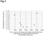
- FIG. 3 is a graph showing a relationship between a total value of a mean chlorine concentration and a mean fluorine concentration in a second core and transmission loss.
- the horizontal axis indicates the total value of the mean chlorine concentration and the mean fluorine concentration in the second core.
- the vertical axis indicates transmission loss at a wavelength of 1550 nm.
- the transmission loss increases. This is considered to be because the viscosity of the second core portion increases and the density fluctuation component of the Rayleigh scattering loss increases as the chlorine concentration and the fluorine concentration decrease.
- the total value is about 5000 ppm, the transmission loss increases. This is considered to be because an increase in the concentration fluctuation component of the Rayleigh scattering loss is larger than a reduction in the density fluctuation component of the Rayleigh scattering loss due to a reduction in viscosity as the chlorine concentration and the fluorine concentration increase.
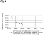
- FIG. 4 is a graph showing a relationship between a difference between a mean fluorine concentration in a cladding and a mean fluorine concentration in the second core and transmission loss.
- the horizontal axis indicates the difference between the mean fluorine concentration in the cladding and the mean fluorine concentration in the second core.
- the vertical axis indicates transmission loss at a wavelength of 1550 nm. As shown in FIG. 4 , the larger the difference between the mean fluorine concentration in the cladding and the mean fluorine concentration in the second core, the smaller the transmission loss.
- Table 2 is a table summarizing specifications of eight types of optical fibers manufactured and evaluated. This table shows, for each of Fibers 8 to 15, the mean K concentration in the core, the transmission loss ( ⁇ 1.55) at a wavelength of 1550 nm, the core diameter, the cut-off wavelength ( ⁇ cc), the effective cross-sectional area (Aeff), the mean chlorine concentration in the first core, the mean chlorine concentration in the second core, the mean fluorine concentration in the first core, and the mean fluorine concentration in the second core.
- FIG. 5 is a graph showing a relationship between the mean chlorine concentration in the second core and transmission loss.
- the horizontal axis indicates the mean chlorine concentration in the second core.
- the vertical axis indicates transmission loss at a wavelength of 1550 nm.
- the mean chlorine concentration in the second core is less than 300 ppm, the transmission loss increases. This is considered to be because glass defects cannot be completely repaired due to a decrease in chlorine concentration, and an increase in transmission loss derived from glass defects occurs.
- the mean chlorine concentration in the second core is about 5000 ppm, the transmission loss increases. This is considered to be because the concentration fluctuation component of the Rayleigh scattering loss increases.
- Table 3 is a table summarizing specifications of eight types of optical fibers manufactured and evaluated. This table shows, for each of Fibers 16 to 23, the mean K concentration in the core, the transmission loss ( ⁇ 1.55) at a wavelength of 1550 nm, the core diameter, the cut-off wavelength ( ⁇ cc), the effective cross-sectional area (Aeff), the mean chlorine concentration in the first core, the mean chlorine concentration in the second core, the mean fluorine concentration in the first core, and the mean fluorine concentration in the second core.
- FIG. 6 is a graph showing a relationship between a mean potassium concentration of a core and transmission loss.
- the horizontal axis indicates the mean potassium concentration in the core.
- the vertical axis indicates transmission loss at a wavelength of 1550 nm.
- the transmission loss deteriorates. This is considered to be because the density fluctuation component of the Rayleigh scattering loss increases due to the insufficient potassium concentration.
- the mean potassium concentration in the core is about 300 ppm, an increase in transmission loss occurs. This is considered to be because the concentration fluctuation component of the Rayleigh scattering loss increases.
- Table 4 is a table summarizing specifications of six types of optical fibers manufactured and evaluated. This table shows, for each of Fibers 24 to 29, the mean K concentration in the core, the transmission loss ( ⁇ 1.55) at a wavelength of 1550 nm, the core diameter, the cut-off wavelength ( ⁇ cc), the effective cross-sectional area (Aeff), the presence or absence of the OD group, the mean chlorine concentration in the first core, the mean chlorine concentration in the second core, the mean fluorine concentration in the first core, and the mean fluorine concentration in the second core.
- Table 5 is a table summarizing specifications of 13 types of optical fiber preforms manufactured and evaluated. This table shows, for each of Preforms 1 to 13, the mean K concentration in the core portion, the mean chlorine concentration in the first core portion, the mean chlorine concentration in the second core portion, the mean fluorine concentration in the first core portion, the mean fluorine concentration in the second core portion, and the number of preform abnormalities.
- the preform abnormality refers to, for example, a portion where a part of glass such as the core portion is crystallized. When the portion having the preform abnormality is drawn, a defect such as unstable fiber diameter may occur due to a difference in thermal expansion coefficient between the glass portion and the crystal portion.
- the number of preform abnormalities is the number of preform abnormal locations included in one preform.
- the size of the optical fiber preform is the same in all of Preform 1 to Preform 13.
- Mean K concentration in core portion [ppm] Mean Cl concentration in first core portion [ppm] Mean Cl concentration in second core portion [ppm] Mean F concentration in first core portion [ppm] Mean F concentration in second core portion [ppm] Number of preform abnormalities Preform 1 44 125 2511 2593 2054 0 Preform 2 44 208 2578 2586 2025 0 Preform 3 41 307 2587 2598 2044 1 Preform 4 43 509 2557 2552 2064 3 Preform 5 43 1002 2539 2554 2070 4 Preform 6 44 1504 2541 2552 2094 10 Preform 7 44 205 2508 1010 2071 0 Preform 8 41 202 2551 1551 2075 0 Preform 9 40 205 2522 2015 2014 0 Preform 10 42 207 2503 2576 2023 1 Preform 11 42 206 2577 3031 2062 3 Preform 12 42 210 2550 4041 2070 4 Preform 13 41 202 2503 5083 20
- the preform abnormality is caused by a crystal generated by a compound such as KCl or KF.
Landscapes
- Chemical & Material Sciences (AREA)
- Physics & Mathematics (AREA)
- Optics & Photonics (AREA)
- Life Sciences & Earth Sciences (AREA)
- Engineering & Computer Science (AREA)
- Chemical Kinetics & Catalysis (AREA)
- General Chemical & Material Sciences (AREA)
- Geochemistry & Mineralogy (AREA)
- Materials Engineering (AREA)
- Organic Chemistry (AREA)
- General Physics & Mathematics (AREA)
- Glass Compositions (AREA)
Abstract
Description
- The present disclosure relates to an optical fiber and an optical fiber preform. The present application claims priority to
Japanese Patent Application No. 2021-117840 filed on July 16, 2021 - In general, when an optical fiber is manufactured by drawing an optical fiber preform in which a core formed of silica-based glass includes an alkali metal element or an alkaline earth metal element, viscosity of the core may be reduced and rearrangement of the glass may be promoted, so that transmission loss caused by Rayleigh scattering of the optical fiber is reduced. Hereinafter, both the alkali metal element and the alkaline earth metal element are referred to as an "alkali metal element group".
- When chlorine is not included in a core including an alkali metal element group or when the content of chlorine is small, the alkali metal element group added to the central portion of the core in the state of an optical fiber preform is diffused during drawing, and at that time, the bond of the glass molecular structure is cut to generate glass defects. This causes an increase in transmission loss derived from glass defects. When the core includes a sufficient amount of chlorine, the alkali metal element group is bonded to glass defects by chlorine. As a result, the occurrence of glass defects is suppressed, and an increase in transmission loss derived from glass defects is reduced.
- In order to reduce such an increase in transmission loss due to glass defects, the core of the optical fiber of the inventions disclosed in
Patent Literatures Patent Literatures -
- Patent Literature 1:
Japanese Unexamined Patent Publication No. 2009-541796 - Patent Literature 2:
Japanese Unexamined Patent Publication No. 2017-76053 - Patent Literature 3:
Japanese Unexamined Patent Publication No. 2019-191297 - An optical fiber according to an embodiment of the present disclosure is an optical fiber made of silica-based glass, including: a core; and a cladding circumscribing the core, in which a refractive index of the core is larger than a refractive index of the cladding, the core includes a first core having a central axis and a second core circumscribing the first core, a mean value of a mass fraction of chlorine in the first core is lower than a mean value of a mass fraction of chlorine in the second core, a mean value of a mass fraction of fluorine in the first core is higher than a mean value of a mass fraction of fluorine in the second core, a total value of the mean value of the mass fraction of chlorine and the mean value of the mass fraction of fluorine in the second core is 5000 ppm or less, and the core includes either or both of an alkali metal element and an alkaline earth metal element.
- An optical fiber preform according to an embodiment of the present disclosure includes: a core portion; and a cladding portion circumscribing the core portion, in which a refractive index of the core portion is larger than a refractive index of the cladding portion, the core portion includes a first core portion having a central axis and a second core portion circumscribing the first core portion, a mean value of a mass fraction of chlorine in the first core portion is lower than a mean value of a mass fraction of chlorine in the second core portion, a mean value of a mass fraction of fluorine in the first core portion is higher than a mean value of a mass fraction of fluorine in the second core portion, a total value of the mean value of the mass fraction of chlorine and the mean value of the mass fraction of fluorine in the second core portion is 5000 ppm or less, and the core portion includes either or both of an alkali metal element and an alkaline earth metal element.
-
-
FIG. 1 is a cross-sectional view of an optical fiber according to an embodiment. -
FIG. 2 is a flowchart illustrating a method for manufacturing an optical fiber according to an embodiment. -
FIG. 3 is a graph showing a relationship between a total value of a mean value of a mass fraction of chlorine and a mean value of a mass fraction of fluorine in a second core and transmission loss. -
FIG. 4 is a graph showing a relationship between a difference between a mean fluorine concentration in a cladding and a mean fluorine concentration in the second core and transmission loss. -
FIG. 5 is a graph showing a relationship between the mean value of the mass fraction of chlorine in the second core and transmission loss. -
FIG. 6 is a graph showing a relationship between a mean potassium concentration of a core and transmission loss. - In the optical fibers disclosed in
Patent Literatures Patent Literatures - An object of the present disclosure is to provide an optical fiber and an optical fiber preform that achieve both manufacturability and reduction in transmission loss.
- According to the present disclosure, it is possible to provide an optical fiber and an optical fiber preform that achieve both manufacturability and reduction in transmission loss.
- Embodiments of the present disclosure are first listed and described. An optical fiber according to an embodiment of the present disclosure is an optical fiber made of silica-based glass, including: a core; and a cladding circumscribing the core, in which a refractive index of the core is larger than a refractive index of the cladding, the core includes a first core having a central axis and a second core circumscribing the first core, a mean value of a mass fraction of chlorine (hereinafter, referred to as "mean chlorine concentration") in the first core is lower than a mean chlorine concentration in the second core, a mean value of a mass fraction of fluorine (hereinafter, referred to as "mean fluorine concentration") in the first core is higher than a mean fluorine concentration in the second core, a total value of the mean chlorine concentration and the mean fluorine concentration in the second core is 5000 ppm or less, and the core includes either or both of an alkali metal element and an alkaline earth metal element. For example, when the mean chlorine concentration is 2000 ppm and the mean fluorine concentration is 2000 ppm, the total value of the mean chlorine concentration and the mean fluorine concentration is 4000 ppm.
- In the optical fiber, both manufacturability and reduction in transmission loss can be achieved.
- The mean chlorine concentration in the first core may be 10 ppm or greater and 500 ppm or less. In this case, both manufacturability and reduction in transmission loss can be easily achieved. When the mean chlorine concentration in the first core is less than 10 ppm, chlorine bonded to glass defects generated during drawing is insufficient, and the transmission loss increases. When the mean chlorine concentration in the first core is greater than 500 ppm, preform defects may occur due to reaction with an alkali metal element group during manufacturing of the preform.
- The mean chlorine concentration in the second core may be 500 ppm or greater and 3000 ppm or less. In this case, both manufacturability and reduction in transmission loss can be easily achieved. When the mean chlorine concentration in the second core is less than 500 ppm, chlorine bonded to glass defects generated during drawing is insufficient, and the transmission loss increases. When the mean chlorine concentration in the second core is greater than 3000 ppm, although the second core does not include the alkali metal element group at the preform stage, a preform defect may occur due to reaction with the alkali metal element group due to diffusion during manufacturing of the preform.
- The mean fluorine concentration in the first core may be 500 ppm or greater and 4000 ppm or less. In this case, both manufacturability and reduction in transmission loss can be easily achieved. When the mean fluorine concentration in the first core is less than 500 ppm, reduction of Rayleigh scattering loss due to viscosity reduction is insufficient, and the transmission loss increases. When the mean fluorine concentration in the first core is greater than 4000 ppm, the transmission loss increases due to concentration fluctuation.
- The mean fluorine concentration in the second core may be 500 ppm or greater and 4000 ppm or less. In this case, both manufacturability and reduction in transmission loss can be easily achieved. When the mean fluorine concentration in the second core is less than 500 ppm, reduction of Rayleigh scattering loss due to viscosity reduction is insufficient, and the transmission loss increases. When the mean fluorine concentration in the second core is greater than 4000 ppm, the transmission loss increases due to concentration fluctuation. By adding fluorine to the second core, the viscosity of the core decreases as compared with the case of using chlorine alone, and the transmission loss caused by Rayleigh scattering can be reduced.
- The total mean value of mass fractions (hereinafter, referred to as "mean concentration") of the alkali metal element and the alkaline earth metal element in the core may be 0.2 ppm or greater and 200 ppm or less. In this case, both manufacturability and reduction in transmission loss can be easily achieved. When the mean concentration is less than 0.2 ppm, reduction of Rayleigh scattering loss due to viscosity reduction is insufficient, and the transmission loss increases. When the mean concentration is greater than 200 ppm, the transmission loss increases due to concentration fluctuation.
- The mean concentration of the alkali metal element and the alkaline earth metal element in the core may be 30 ppm or greater. In this case, both manufacturability and reduction in transmission loss can be more easily achieved.
- The core may include any one of sodium, potassium, rubidium, cesium, and calcium as the alkali metal element or the alkaline earth metal element. In this case, reduction in transmission loss can be easily realized.
- In the optical fiber of the present disclosure with sufficiently reduced transmission loss, the transmission loss is not deteriorated even under radiation. That is, the transmission loss can be reduced even without an OD group. When the chlorine concentration is high, glass defects are suppressed, and such transmission loss can be reduced.
- A difference between a mean value of a mass fraction of fluorine in the cladding and the mean value of the mass fraction of fluorine in the second core may be 8400 ppm or greater. In this case, transmission loss can be further reduced.
- The difference between the mean value of the mass fraction of fluorine in the cladding and the mean value of the mass fraction of fluorine in the second core may be 8600 ppm or greater and 9000 ppm or less. In this case, transmission loss can be suppressed.
- The mean value of the mass fraction of fluorine in the cladding may be 8000 ppm or greater and 13000 ppm or less. In this case, transmission loss can be further reduced.
- An optical fiber preform according to an embodiment of the present disclosure includes: a core portion; and a cladding portion circumscribing the core portion, in which a refractive index of the core portion is larger than a refractive index of the cladding portion, the core portion includes a first core portion having a central axis and a second core portion circumscribing the first core portion, a mean chlorine concentration in the first core portion is lower than a mean chlorine concentration in the second core portion, a mean fluorine concentration in the first core portion is higher than a mean fluorine concentration in the second core portion, a total value of the mean chlorine concentration and the mean fluorine concentration in the second core portion is 5000 ppm or less, and the core portion includes either or both of an alkali metal element and an alkaline earth metal element.
- In the optical fiber preform, both manufacturability of the optical fiber and reduction in transmission loss can be achieved.
- The mean concentration of chlorine in the first core portion may be 1000 ppm or less. In this case, the occurrence of preform abnormality can be suppressed. Here, the preform abnormality refers to a portion where a part of glass such as the core portion is crystallized.
- The mean concentration of fluorine in the first core portion may be 5000 ppm or less. In this case, the occurrence of preform abnormality can be suppressed.
- Specific examples of the optical fiber and the optical fiber preform of the present disclosure will be described below with reference to the drawings. It should be noted that the present invention is not limited to these examples, but is indicated by the scope of the claims and is intended to include all modifications within the meaning and scope equivalent to the scope of the claims. In the description of the drawings, the same elements are denoted by the same reference numerals, and redundant description will be omitted.
-
FIG. 1 is a cross-sectional view of an optical fiber according to an embodiment. Anoptical fiber 1 is made of silica-based glass.Optical fiber 1 includes acore 10 and acladding 20.Core 10 has a central axis C ofoptical fiber 1.Cladding 20 surroundscore 10 and circumscribescore 10. The refractive index ofcore 10 is larger than the refractive index ofcladding 20. -
Core 10 includes afirst core 11 and asecond core 12.First core 11 has central axisC. Second core 12 surroundsfirst core 11 and circumscribesfirst core 11.Cladding 20 includes a first cladding and a second cladding (not illustrated). The first cladding surroundscore 10 and circumscribescore 10. The second cladding surrounds the first cladding and circumscribes the first cladding. -
Core 10 includes chlorine, fluorine, and an alkali metal element group. The mean chlorine concentration infirst core 11 is 10 ppm or greater and 500 ppm or less. The mean chlorine concentration insecond core 12 is 500 ppm or greater and 3000 ppm or less. The mean chlorine concentration infirst core 11 is lower than the mean chlorine concentration insecond core 12. The mean fluorine concentration infirst core 11 is 500 ppm or greater and 4000 ppm or less. The mean fluorine concentration insecond core 12 is 500 ppm or greater and 4000 ppm or less. The mean fluorine concentration infirst core 11 is higher than the mean fluorine concentration insecond core 12. The total value of the mean chlorine concentration and the mean fluorine concentration insecond core 12 is 5000 ppm or less. -
Core 10 includes the alkali metal element group. The mean concentration of the alkali metal element group incore 10 is 0.2 ppm or greater and 200 ppm or less.Core 10 includes any one of sodium, potassium, rubidium, cesium, and calcium as the alkali metal element or the alkaline earth metal element. -
Optical fiber 1 is manufactured by drawing the optical fiber preform according to an embodiment. The optical fiber preform is made of silica-based glass. The optical fiber preform includes a core portion serving ascore 10 and a cladding portion serving ascladding 20. The core portion has a central axis of the optical fiber preform corresponding to central axis C. The cladding portion surrounds the core portion and circumscribes the core portion. A refractive index of the core portion is larger than a refractive index of the cladding portion. - The core portion includes a first core portion serving as
first core 11 and a second core portion serving assecond core 12. The first core portion has central axis C. The second core portion surrounds the first core portion and circumscribes the first core portion. The cladding portion includes a first cladding portion serving as the first cladding and a second cladding portion serving as the second cladding. The first cladding portion surrounds the core portion and circumscribes the core portion. The second cladding portion surrounds the first cladding portion and circumscribes the first cladding portion. Since the type and concentration of the dopant in the optical fiber preform correspond to the type and concentration of the dopant inoptical fiber 1, detailed description thereof will be omitted. The alkali metal element group is added to the first core portion and diffuses during drawing. -
FIG. 2 is a flowchart illustrating a method for manufacturing an optical fiber according to an embodiment. It should be noted that, in the following description, an example of specific conditions is also described.Optical fiber 1 is manufactured by sequentially performing a preparation process S1, an addition process S2, a diameter reduction process S3, an etching process S4, a solidification process S5, a first stretching and grinding process S6, a first rod-in collapse process S7, a second stretching and grinding process S8, a second rod-in collapse process S9, an OVD process S10, and a drawing process S11. The method for manufacturingoptical fiber 1 includes these processes S1 to S11. The method for manufacturing the optical fiber preform includes these processes S1 to S10. - In the preparation process S1, a first core pipe and a second core pipe are prepared. The first core pipe is a glass pipe made of silica-based glass and becomes
first core 11 through the first core portion. The first core pipe is prepared as a glass pipe for diffusing a dopant such as an alkali metal element. A silica-based glass cylindrical body as the base of the first core pipe includes 10 ppm or greater and 500 ppm or less of chlorine and 500 ppm or greater and 4000 ppm or less of fluorine. The concentration of other dopants and impurities is 10 ppm or less. An outer diameter of the first core pipe is 30 mm or more and 40 mm or less. An inner diameter is 15 mm or more and 25 mm or less. - The method for measuring the chlorine concentration is, for example, as follows. An end face of
optical fiber 1 perpendicular to the fiber axis (central axis C) is polished, and the chlorine concentration is measured by an electron probe micro analyzer (EPMA) at each position along a straight line passing through the central position of the end face of the optical fiber. The conditions of measurement by EPMA are, for example, acceleration voltage of 20 kV, probe beam diameter of 1 µm or less, and measurement interval of 100 nm or less. The same applies to a method for measuring concentrations of other elements. - The mean value of the mass fraction (mean concentration) described in the present specification is, for example, a concentration represented by the following equation (1) in the case of a mean fluorine concentration of the silica-based glass cylindrical body. F(r) represents a fluorine concentration at a position of a radius r. c represents a radius of the silica-based glass cylindrical body. As in the case of
optical fiber 1, the concentration is measured by, for example, EPMA, but the measurement concentrations may be different from those in the case ofoptical fiber 1. There is no problem as long as the concentration is calculated using the calibration curve under respective conditions.
[Formula 1]
- The second core pipe is a glass pipe made of silica-based glass and becomes
second core 12 through the second core portion. An outer diameter of the second core pipe is 40 mm or more and 90 mm or less. An inner diameter of the second core pipe is 15 mm or more and 30 mm or less. - In the present embodiment, the preparation process S1 is performed before the addition process S2, but the second core pipe may be prepared before the first rod-in collapse process S7. That is, the preparation process S1 may include a first core pipe preparation process performed before the addition process S2 and a second core pipe preparation process performed before the second rod-in collapse process S7.
- In the addition process S2, a potassium (K) element is added to the inner surface of the first core pipe as a dopant of the alkali metal element group. As a raw material, 6 g or more and 10 g or less of potassium bromide (KBr) is used. This raw material is heated to a temperature of 750°C or more and 850°C or less by an external heat source to generate raw material vapor. While the raw material vapor is introduced into the first core pipe together with a carrier gas composed of oxygen at a flow rate of 1 SLM or more and 3 SLM or less (1 liter/min or more and 3 liter/min or less in terms of standard conditions), the first core pipe is heated by an oxyhydrogen burner from the outside such that the outer surface of the first core pipe has a temperature of 1600°C or more and 1800°C or less. At this time, the heating is performed by traversing the burner at a speed of 30 mm/min or more and 60 mm/min or less in a total of 10 or more and 15 turns or less so that the K element is diffused and added to the inner surface of the first core pipe.
- In the diameter reduction process S3, the diameter of the first core pipe to which K is added is reduced. At this time, the first core pipe is heated by the external heat source so that the outer surface of the first core pipe becomes 2000°C or more and 2300°C or less while flowing oxygen into the first core pipe in a range of 0.5 SLM or more and 1.0 SLM or less. The heating is performed by traversing the external heat source in a total of 6 turns or more and 10 turns or less so that the diameter of the first core pipe is reduced until the inner diameter thereof becomes 3 mm or more and 6 mm or less.
- In the etching process S4, the inner surface of the first core pipe is etched. At this time, vapor phase etching is performed by heating the first core pipe by the external heat source while a mixed gas of SF6 (0.2 SLM or more and 0.4 SLM or less) and chlorine (0.5 SLM or more and 1.0 SLM or less) is introduced into the first core pipe. In this way, the inner surface of the first core pipe containing impurities added together with the target dopant at a high concentration can be scraped, and the impurities can be removed.
- In the solidification process S5, the first core pipe is solidified. In the solidification process S5, a mixed gas of oxygen (0.1 SLM or more and 0.5 SLM or less) and He (0.5 SLM or more and 1.0 SLM or less) is introduced into the first core pipe, and the first core pipe is solidified by setting the surface temperature to 2000°C or more and 2300°C while reducing the absolute pressure in the first core pipe to 97 kPa or less. By this solidification, a first core portion (a diameter of 20 mm or more and 30 mm or less) is obtained.
- In the first stretching and grinding process S6, the first core portion is stretched to have a diameter of 20 mm or more and 30 mm or less, and the outer peripheral portion of the first core portion is ground to have a diameter of 15 mm or more and 25 mm or less.
- In the first rod-in collapse process S7, the first core portion obtained up to the first stretching and grinding process S6 is used as a rod, and the second core pipe prepared in the preparation process S1 is used as a pipe to perform rod-in collapse. According to this rod-in collapse method, the first core portion and the second core pipe are heated and integrated by the external heat source. As a result, the second core portion is formed around the first core portion. As a result, a core portion (a diameter of 20 mm or more and 90 mm or less) is obtained.
- In the second stretching and grinding process S8, the core portion is stretched to have a diameter of 20 mm or more and 35 mm or less, and the outer peripheral portion of the core portion is ground to have a diameter of 15 mm or more and 25 mm or less.
- In the second rod-in collapse process S9, the core portion obtained up to the second stretching and grinding process S8 is used as a rod, and a silica-based glass pipe to which fluorine is added is used as a pipe to perform rod-in collapse. According to this rod-in collapse method, the core portion and the silica-based glass pipe to which fluorine is added are heated and integrated by the external heat source. As a result, the first cladding portion is formed around the core portion. A difference in relative refractive index between the core portion and the first cladding portion is about 0.34% at the maximum. As a result of the synthesis by the rod-in-collapse method, it is possible to suppress the amount of the OH group in the core portion and the first cladding portion in the vicinity thereof to be sufficiently low.
- In the OVD process S10, first, a rod in which the core portion and the first cladding portion are integrated is stretched to have a predetermined radius. Subsequently, the second cladding portion including fluorine on the outside of the rod having a predetermined radius is synthesized by an OVD method. As a result, an optical fiber preform is manufactured.
- In the drawing process S11,
optical fiber 1 is manufactured by drawing the optical fiber preform manufactured by the method for manufacturing the optical fiber preform described above. The drawing speed is 1800 m/min or more and 2300 m/min or less. The drawing tension is, for example, 0.5 N. - Table 1 is a table summarizing specifications of seven types of optical fibers manufactured and evaluated. This table shows, for each of
Fibers 1 to 7, the mean K concentration in the core, the transmission loss (α1.55) at a wavelength of 1550 nm, the core diameter, the cut-off wavelength (λcc), the effective cross-sectional area (Aeff), the mean chlorine concentration in the first core, the mean chlorine concentration in the second core, the mean fluorine concentration in the first core, the mean fluorine concentration in the second core, the sum of the mean chlorine concentration and the mean fluorine concentration in the second core, the mean fluorine concentration in the cladding, and the difference between the mean fluorine concentration in the cladding and the mean fluorine concentration in the second core. Here, the cladding refers to the entire cladding including the first cladding and the second cladding. The various concentrations in the present specification are not concentrations in the optical fiber but concentrations in the glass pipes serving as the first core and the second core after manufacturing. However, the concentration in the optical fiber can also be acquired. A boundary between the first core and the second core in the optical fiber is a place where the inclination between the points in the radial direction of the chlorine concentration is the largest in the core. However, depending on the measurement conditions of EPMA, the concentration has noise. In this case, the place of the boundary between the first core and the second core can be calculated after the noise is suppressed using the moving average of the plurality of points.[Table 1] Mean K concentration in core [ppm] α1.55 [dB/km] Core diameter [µm] λcc [nm] Aeff [µm2] Mean Cl concentration in first core [ppm] Mean Cl concentration in second core [ppm] Mean F concentration in first core [ppm] Mean F concentration in second core [ppm] Mean Cl concentration + mean F concentration in second core [ppm] Mean F concentration in cladding [ppm] Mean F concentration in cladding - mean F concentration in second core [ppm] Fiber 144 0.151 11.1 1471 112 123 1007 2566 4023 5030 12300 8277 Fiber 242 0.145 11.2 1484 112 122 1011 2501 3552 4563 12100 8578 Fiber 3 40 0.144 11.1 1507 112 123 1099 2565 2107 3206 11090 8983 Fiber 444 0.144 11.3 1515 112 126 1057 2526 1404 2461 10010 8606 Fiber 540 0.145 11.6 1475 112 130 1075 2582 1043 2118 9560 8517 Fiber 644 0.146 11.3 1508 110 120 1007 2555 883 1890 9320 8437 Fiber 7 41 0.150 11.1 1471 110 128 680 2583 220 900 8520 8300 -
FIG. 3 is a graph showing a relationship between a total value of a mean chlorine concentration and a mean fluorine concentration in a second core and transmission loss. The horizontal axis indicates the total value of the mean chlorine concentration and the mean fluorine concentration in the second core. The vertical axis indicates transmission loss at a wavelength of 1550 nm. When the total value is less than 1000 ppm, the transmission loss increases. This is considered to be because the viscosity of the second core portion increases and the density fluctuation component of the Rayleigh scattering loss increases as the chlorine concentration and the fluorine concentration decrease. On the other hand, when the total value is about 5000 ppm, the transmission loss increases. This is considered to be because an increase in the concentration fluctuation component of the Rayleigh scattering loss is larger than a reduction in the density fluctuation component of the Rayleigh scattering loss due to a reduction in viscosity as the chlorine concentration and the fluorine concentration increase. -
FIG. 4 is a graph showing a relationship between a difference between a mean fluorine concentration in a cladding and a mean fluorine concentration in the second core and transmission loss. The horizontal axis indicates the difference between the mean fluorine concentration in the cladding and the mean fluorine concentration in the second core. The vertical axis indicates transmission loss at a wavelength of 1550 nm. As shown inFIG. 4 , the larger the difference between the mean fluorine concentration in the cladding and the mean fluorine concentration in the second core, the smaller the transmission loss. This is considered to be because as a difference in refractive index between the core and the cladding, even in the case of the same effective cross-sectional area (Aeff), the power distribution of light tends to concentrate on the core having a low Rayleigh scattering loss. - Table 2 is a table summarizing specifications of eight types of optical fibers manufactured and evaluated. This table shows, for each of Fibers 8 to 15, the mean K concentration in the core, the transmission loss (α1.55) at a wavelength of 1550 nm, the core diameter, the cut-off wavelength (λcc), the effective cross-sectional area (Aeff), the mean chlorine concentration in the first core, the mean chlorine concentration in the second core, the mean fluorine concentration in the first core, and the mean fluorine concentration in the second core.
[Table 2] Mean K concentration in core [ppm] α1.55 [dB/km] Core diameter [µm] λcc [nm] Aeff [µm2] Mean Cl concentration in first core [ppm] Mean Cl concentration in second core [ppm] Mean F concentration in first core [ppm] Mean F concentration in second core [ppm] Fiber 8 43 0.150 11.6 1511 114 129 5010 2559 2046 Fiber 943 0.147 11.1 1476 115 130 3047 2596 2062 Fiber 1041 0.146 11.3 1502 113 122 2540 2545 2079 Fiber 1143 0.145 11.5 1508 114 128 2019 2596 2026 Fiber 1243 0.144 11.5 1516 112 124 1095 2507 2036 Fiber 13 43 0.144 11.4 1484 111 123 627 2550 2098 Fiber 14 42 0.148 11.2 1472 113 124 290 2573 2060 Fiber 15 40 0.150 11.6 1515 113 127 80 2568 2016 -
FIG. 5 is a graph showing a relationship between the mean chlorine concentration in the second core and transmission loss. The horizontal axis indicates the mean chlorine concentration in the second core. The vertical axis indicates transmission loss at a wavelength of 1550 nm. When the mean chlorine concentration in the second core is less than 300 ppm, the transmission loss increases. This is considered to be because glass defects cannot be completely repaired due to a decrease in chlorine concentration, and an increase in transmission loss derived from glass defects occurs. On the other hand, when the mean chlorine concentration in the second core is about 5000 ppm, the transmission loss increases. This is considered to be because the concentration fluctuation component of the Rayleigh scattering loss increases. - Table 3 is a table summarizing specifications of eight types of optical fibers manufactured and evaluated. This table shows, for each of Fibers 16 to 23, the mean K concentration in the core, the transmission loss (α1.55) at a wavelength of 1550 nm, the core diameter, the cut-off wavelength (λcc), the effective cross-sectional area (Aeff), the mean chlorine concentration in the first core, the mean chlorine concentration in the second core, the mean fluorine concentration in the first core, and the mean fluorine concentration in the second core.
[Table 3] Mean K concentration in core [ppm] α1.55 [dB/km] Core diameter [µm] λcc [nm] Aeff [µm2] Mean Cl concentration in first core [ppm] Mean Cl concentration in second core [ppm] Mean F concentration in first core [ppm] Mean F concentration in second core [ppm] Fiber 16 10 0.150 11.0 1491 111 123 1012 2566 2056 Fiber 17 22 0.147 11.1 1507 113 124 1096 2506 2028 Fiber 18 33 0.146 11.3 1513 112 127 1033 2548 2033 Fiber 19 62 0.145 11.4 1499 111 127 1000 2521 2011 Fiber 20102 0.144 11.2 1479 112 128 1058 2540 2011 Fiber 21 152 0.144 11.5 1480 114 122 1030 2573 2064 Fiber 22 203 0.146 11.3 1485 110 121 1057 2549 2004 Fiber 23 301 0.150 11.4 1472 111 125 1063 2599 2044 -
FIG. 6 is a graph showing a relationship between a mean potassium concentration of a core and transmission loss. The horizontal axis indicates the mean potassium concentration in the core. The vertical axis indicates transmission loss at a wavelength of 1550 nm. As the mean potassium concentration in the core decreases, the transmission loss deteriorates. This is considered to be because the density fluctuation component of the Rayleigh scattering loss increases due to the insufficient potassium concentration. On the other hand, when the mean potassium concentration in the core is about 300 ppm, an increase in transmission loss occurs. This is considered to be because the concentration fluctuation component of the Rayleigh scattering loss increases. - Table 4 is a table summarizing specifications of six types of optical fibers manufactured and evaluated. This table shows, for each of Fibers 24 to 29, the mean K concentration in the core, the transmission loss (α1.55) at a wavelength of 1550 nm, the core diameter, the cut-off wavelength (λcc), the effective cross-sectional area (Aeff), the presence or absence of the OD group, the mean chlorine concentration in the first core, the mean chlorine concentration in the second core, the mean fluorine concentration in the first core, and the mean fluorine concentration in the second core.
[Table 4] Mean K concentration in core [ppm] α1.55 [dB/km] Core diameter [µm] λcc [nm] Aeff [µm2] Presence or absence of OD group Mean Cl concentration in first core [ppm] Mean Cl concentration in second core [ppm] Mean F concentration in first core [ppm] Mean F concentration in second core [ppm] Fiber 24 54 0.144 11.6 1516 111 Present 129 304 2594 2015 Fiber 25 51 0.144 11.2 1501 115 Present 130 501 2516 2075 Fiber 26 51 0.145 11.5 1492 113 Present 130 1011 2569 2061 Fiber 27 51 0.148 11.1 1502 112 Absent 127 299 2572 2089 Fiber 28 53 0.145 11.5 1472 110 Absent 122 554 2551 2066 Fiber 29 52 0.144 11.3 1472 112 Absent 125 1107 2598 2100 - For Fibers 24 to 26, a treatment (deuterium (D2) treatment) of exposing the fiber to a deuterium gas atmosphere after the drawing process S11. For Fibers 27 to 29, the D2 treatment was not performed. It was confirmed that an increase in transmission loss occurs when the mean chlorine concentration in the second core is less than 300 ppm. This is considered to be because glass defects occurred.
- Table 5 is a table summarizing specifications of 13 types of optical fiber preforms manufactured and evaluated. This table shows, for each of
Preforms 1 to 13, the mean K concentration in the core portion, the mean chlorine concentration in the first core portion, the mean chlorine concentration in the second core portion, the mean fluorine concentration in the first core portion, the mean fluorine concentration in the second core portion, and the number of preform abnormalities. The preform abnormality refers to, for example, a portion where a part of glass such as the core portion is crystallized. When the portion having the preform abnormality is drawn, a defect such as unstable fiber diameter may occur due to a difference in thermal expansion coefficient between the glass portion and the crystal portion. The number of preform abnormalities is the number of preform abnormal locations included in one preform. The size of the optical fiber preform is the same in all ofPreform 1 to Preform 13.[Table 5] Mean K concentration in core portion [ppm] Mean Cl concentration in first core portion [ppm] Mean Cl concentration in second core portion [ppm] Mean F concentration in first core portion [ppm] Mean F concentration in second core portion [ppm] Number of preform abnormalities Preform 1 44 125 2511 2593 2054 0 Preform 244 208 2578 2586 2025 0 Preform 3 41 307 2587 2598 2044 1 Preform 443 509 2557 2552 2064 3 Preform 543 1002 2539 2554 2070 4 Preform 644 1504 2541 2552 2094 10 Preform 7 44 205 2508 1010 2071 0 Preform 8 41 202 2551 1551 2075 0 Preform 940 205 2522 2015 2014 0 Preform 1042 207 2503 2576 2023 1 Preform 1142 206 2577 3031 2062 3 Preform 1242 210 2550 4041 2070 4 Preform 13 41 202 2503 5083 2042 8 - When the mean chlorine concentration or mean fluorine concentration in the first core portion increases, the number of preform abnormalities increases. It is considered that the preform abnormality is caused by a crystal generated by a compound such as KCl or KF.
-
- 1
- Optical fiber
- 10
- Core
- 11
- First core
- 12
- Second core
- 20
- Cladding
- C
- Central axis
Claims (15)
- An optical fiber made of silica-based glass, comprising:a core; anda cladding circumscribing the core,wherein a refractive index of the core is larger than a refractive index of the cladding,the core includes a first core having a central axis and a second core circumscribing the first core,a mean value of a mass fraction of chlorine in the first core is lower than a mean value of a mass fraction of chlorine in the second core,a mean value of a mass fraction of fluorine in the first core is higher than a mean value of a mass fraction of fluorine in the second core,a total value of the mean value of the mass fraction of chlorine and the mean value of the mass fraction of fluorine in the second core is 5000 ppm or less, andthe core includes either or both of an alkali metal element and an alkaline earth metal element.
- The optical fiber according to claim 1, wherein
the mean value of the mass fraction of chlorine in the first core is 10 ppm or greater and 500 ppm or less. - The optical fiber according to claim 1 or 2, wherein
the mean value of the mass fraction of chlorine in the second core is 500 ppm or greater and 3000 ppm or less. - The optical fiber according to any one of claims 1 to 3, wherein
the mean value of the mass fraction of fluorine in the first core is 500 ppm or greater and 4000 ppm or less. - The optical fiber according to any one of claims 1 to 4, wherein
the mean value of the mass fraction of fluorine in the second core is 500 ppm or greater and 4000 ppm or less. - The optical fiber according to any one of claims 1 to 5, wherein
a total mean value of mass fractions of the alkali metal element and the alkaline earth metal element in the core is 0.2 ppm or greater and 200 ppm or less. - The optical fiber according to claim 6, wherein
the total mean value of mass fractions of the alkali metal element and the alkaline earth metal element in the core is 30 ppm or greater. - The optical fiber according to any one of claims 1 to 7, wherein
the core includes any one of sodium, potassium, rubidium, cesium, and calcium as the alkali metal element or the alkaline earth metal element. - The optical fiber according to any one of claims 1 to 8,
not comprising an OD group. - The optical fiber according to any one of claims 1 to 9, wherein
a difference between a mean value of a mass fraction of fluorine in the cladding and the mean value of the mass fraction of fluorine in the second core is 8400 ppm or greater. - The optical fiber according to any one of claims 1 to 10, wherein
the difference between the mean value of the mass fraction of fluorine in the cladding and the mean value of the mass fraction of fluorine in the second core is 8600 ppm or greater and 9000 ppm or less. - The optical fiber according to any one of claims 1 to 11, wherein
the mean value of the mass fraction of fluorine in the cladding is 8000 ppm or greater and 13000 ppm or less. - An optical fiber preform made of silica-based glass, comprising:a core portion; anda cladding portion circumscribing the core portion,wherein a refractive index of the core portion is larger than a refractive index of the cladding portion,the core portion includes a first core portion having a central axis and a second core portion circumscribing the first core portion,a mean value of a mass fraction of chlorine in the first core portion is lower than a mean value of a mass fraction of chlorine in the second core portion,a mean value of a mass fraction of fluorine in the first core portion is higher than a mean value of a mass fraction of fluorine in the second core portion,a total value of the mean value of the mass fraction of chlorine and the mean value of the mass fraction of fluorine in the second core portion is 5000 ppm or less, andthe core portion includes either or both of an alkali metal element and an alkaline earth metal element.
- The optical fiber preform according to claim 13, wherein
the mean value of the mass fraction of chlorine in the first core portion is 1000 ppm or less. - The optical fiber preform according to claim 13 or 14, wherein
the mean value of the mass fraction of fluorine in the first core portion is 5000 ppm or less.
Applications Claiming Priority (2)
| Application Number | Priority Date | Filing Date | Title |
|---|---|---|---|
| JP2021117840 | 2021-07-16 | ||
| PCT/JP2022/025961 WO2023286608A1 (en) | 2021-07-16 | 2022-06-29 | Optical fiber and optical fiber base material |
Publications (2)
| Publication Number | Publication Date |
|---|---|
| EP4372433A1 true EP4372433A1 (en) | 2024-05-22 |
| EP4372433A4 EP4372433A4 (en) | 2024-10-23 |
Family
ID=84920056
Family Applications (1)
| Application Number | Title | Priority Date | Filing Date |
|---|---|---|---|
| EP22841952.9A Withdrawn EP4372433A4 (en) | 2021-07-16 | 2022-06-29 | OPTICAL FIBER AND BASE MATERIAL FOR OPTICAL FIBER |
Country Status (5)
| Country | Link |
|---|---|
| US (1) | US20240327271A1 (en) |
| EP (1) | EP4372433A4 (en) |
| JP (1) | JPWO2023286608A1 (en) |
| CN (1) | CN117581128A (en) |
| WO (1) | WO2023286608A1 (en) |
Family Cites Families (6)
| Publication number | Priority date | Publication date | Assignee | Title |
|---|---|---|---|---|
| KR101066281B1 (en) * | 2003-08-29 | 2011-09-20 | 코닝 인코포레이티드 | Optical fiber containing an alkali metal oxide, and its manufacturing method and apparatus |
| US7536076B2 (en) * | 2006-06-21 | 2009-05-19 | Corning Incorporated | Optical fiber containing alkali metal oxide |
| US9020316B2 (en) * | 2013-02-28 | 2015-04-28 | Corning Incorporated | Low attenuation optical fibers with an F-graded index core |
| JP6551137B2 (en) | 2015-10-15 | 2019-07-31 | 住友電気工業株式会社 | Optical fiber |
| JP7119531B2 (en) | 2018-04-20 | 2022-08-17 | 住友電気工業株式会社 | optical fiber |
| JP2021117840A (en) | 2020-01-28 | 2021-08-10 | トヨタ自動車株式会社 | Information processing device, information processing method, and program |
-
2022
- 2022-06-29 JP JP2023535228A patent/JPWO2023286608A1/ja active Pending
- 2022-06-29 US US18/577,839 patent/US20240327271A1/en active Pending
- 2022-06-29 WO PCT/JP2022/025961 patent/WO2023286608A1/en not_active Ceased
- 2022-06-29 CN CN202280041861.7A patent/CN117581128A/en active Pending
- 2022-06-29 EP EP22841952.9A patent/EP4372433A4/en not_active Withdrawn
Also Published As
| Publication number | Publication date |
|---|---|
| CN117581128A (en) | 2024-02-20 |
| US20240327271A1 (en) | 2024-10-03 |
| WO2023286608A1 (en) | 2023-01-19 |
| JPWO2023286608A1 (en) | 2023-01-19 |
| EP4372433A4 (en) | 2024-10-23 |
Similar Documents
| Publication | Publication Date | Title |
|---|---|---|
| EP2511741B1 (en) | Optical fibre with alkali doped core and optical fiber preform | |
| US9512033B2 (en) | Optical fiber preform | |
| EP2481716B1 (en) | Method for producing a glass optical fiber preform | |
| EP3173388B1 (en) | Method of manufacturing optical fiber preform | |
| EP2484643A1 (en) | Method for producing a glass optical fiber preform | |
| EP3677556B1 (en) | Method for manufacturing optical fiber parent material, and method for manufacturing optical fiber | |
| US10723650B2 (en) | Optical fiber preform | |
| US20230322605A1 (en) | Production method for optical fiber base material, and optical fiber base material | |
| US10656326B2 (en) | Optical fiber | |
| EP4372433A1 (en) | Optical fiber and optical fiber base material | |
| JPWO2023157505A5 (en) | ||
| EP4682598A1 (en) | Multicore optical fiber | |
| EP4053605A1 (en) | Optical fiber | |
| US12398062B2 (en) | Method for producing optical fiber base material, and optical fiber base material | |
| EP4722770A1 (en) | Multicore optical fiber | |
| DK202530761A1 (en) | Reservoir, method for producing optical fiber, and device for producing optical fiber |
Legal Events
| Date | Code | Title | Description |
|---|---|---|---|
| STAA | Information on the status of an ep patent application or granted ep patent |
Free format text: STATUS: THE INTERNATIONAL PUBLICATION HAS BEEN MADE |
|
| PUAI | Public reference made under article 153(3) epc to a published international application that has entered the european phase |
Free format text: ORIGINAL CODE: 0009012 |
|
| STAA | Information on the status of an ep patent application or granted ep patent |
Free format text: STATUS: REQUEST FOR EXAMINATION WAS MADE |
|
| 17P | Request for examination filed |
Effective date: 20231208 |
|
| AK | Designated contracting states |
Kind code of ref document: A1 Designated state(s): AL AT BE BG CH CY CZ DE DK EE ES FI FR GB GR HR HU IE IS IT LI LT LU LV MC MK MT NL NO PL PT RO RS SE SI SK SM TR |
|
| A4 | Supplementary search report drawn up and despatched |
Effective date: 20240919 |
|
| DAV | Request for validation of the european patent (deleted) | ||
| DAX | Request for extension of the european patent (deleted) | ||
| RIC1 | Information provided on ipc code assigned before grant |
Ipc: C03B 37/012 20060101ALN20240913BHEP Ipc: G02B 6/02 20060101ALI20240913BHEP Ipc: C03C 13/04 20060101ALI20240913BHEP Ipc: G02B 6/036 20060101AFI20240913BHEP |
|
| STAA | Information on the status of an ep patent application or granted ep patent |
Free format text: STATUS: THE APPLICATION HAS BEEN WITHDRAWN |
|
| 18W | Application withdrawn |
Effective date: 20250109 |