EP4372290A1 - Humidifier with improved control and floor-standing fan - Google Patents
Humidifier with improved control and floor-standing fan Download PDFInfo
- Publication number
- EP4372290A1 EP4372290A1 EP23178384.6A EP23178384A EP4372290A1 EP 4372290 A1 EP4372290 A1 EP 4372290A1 EP 23178384 A EP23178384 A EP 23178384A EP 4372290 A1 EP4372290 A1 EP 4372290A1
- Authority
- EP
- European Patent Office
- Prior art keywords
- seat
- fits
- hole
- humidifier
- plate
- Prior art date
- Legal status (The legal status is an assumption and is not a legal conclusion. Google has not performed a legal analysis and makes no representation as to the accuracy of the status listed.)
- Granted
Links
Images





Classifications
-
- F—MECHANICAL ENGINEERING; LIGHTING; HEATING; WEAPONS; BLASTING
- F24—HEATING; RANGES; VENTILATING
- F24F—AIR-CONDITIONING; AIR-HUMIDIFICATION; VENTILATION; USE OF AIR CURRENTS FOR SCREENING
- F24F11/00—Control or safety arrangements
- F24F11/0008—Control or safety arrangements for air-humidification
-
- F—MECHANICAL ENGINEERING; LIGHTING; HEATING; WEAPONS; BLASTING
- F24—HEATING; RANGES; VENTILATING
- F24F—AIR-CONDITIONING; AIR-HUMIDIFICATION; VENTILATION; USE OF AIR CURRENTS FOR SCREENING
- F24F6/00—Air-humidification, e.g. cooling by humidification
- F24F6/12—Air-humidification, e.g. cooling by humidification by forming water dispersions in the air
-
- F—MECHANICAL ENGINEERING; LIGHTING; HEATING; WEAPONS; BLASTING
- F04—POSITIVE - DISPLACEMENT MACHINES FOR LIQUIDS; PUMPS FOR LIQUIDS OR ELASTIC FLUIDS
- F04D—NON-POSITIVE-DISPLACEMENT PUMPS
- F04D25/00—Pumping installations or systems
- F04D25/02—Units comprising pumps and their driving means
- F04D25/08—Units comprising pumps and their driving means the working fluid being air, e.g. for ventilation
-
- F—MECHANICAL ENGINEERING; LIGHTING; HEATING; WEAPONS; BLASTING
- F04—POSITIVE - DISPLACEMENT MACHINES FOR LIQUIDS; PUMPS FOR LIQUIDS OR ELASTIC FLUIDS
- F04D—NON-POSITIVE-DISPLACEMENT PUMPS
- F04D29/00—Details, component parts, or accessories
- F04D29/70—Suction grids; Strainers; Dust separation; Cleaning
- F04D29/701—Suction grids; Strainers; Dust separation; Cleaning especially adapted for elastic fluid pumps
- F04D29/705—Adding liquids
-
- F—MECHANICAL ENGINEERING; LIGHTING; HEATING; WEAPONS; BLASTING
- F24—HEATING; RANGES; VENTILATING
- F24F—AIR-CONDITIONING; AIR-HUMIDIFICATION; VENTILATION; USE OF AIR CURRENTS FOR SCREENING
- F24F11/00—Control or safety arrangements
- F24F11/30—Control or safety arrangements for purposes related to the operation of the system, e.g. for safety or monitoring
-
- F—MECHANICAL ENGINEERING; LIGHTING; HEATING; WEAPONS; BLASTING
- F24—HEATING; RANGES; VENTILATING
- F24F—AIR-CONDITIONING; AIR-HUMIDIFICATION; VENTILATION; USE OF AIR CURRENTS FOR SCREENING
- F24F11/00—Control or safety arrangements
- F24F11/70—Control systems characterised by their outputs; Constructional details thereof
-
- F—MECHANICAL ENGINEERING; LIGHTING; HEATING; WEAPONS; BLASTING
- F24—HEATING; RANGES; VENTILATING
- F24F—AIR-CONDITIONING; AIR-HUMIDIFICATION; VENTILATION; USE OF AIR CURRENTS FOR SCREENING
- F24F7/00—Ventilation
- F24F7/007—Ventilation with forced flow
-
- F—MECHANICAL ENGINEERING; LIGHTING; HEATING; WEAPONS; BLASTING
- F24—HEATING; RANGES; VENTILATING
- F24F—AIR-CONDITIONING; AIR-HUMIDIFICATION; VENTILATION; USE OF AIR CURRENTS FOR SCREENING
- F24F6/00—Air-humidification, e.g. cooling by humidification
- F24F2006/008—Air-humidifier with water reservoir
-
- Y—GENERAL TAGGING OF NEW TECHNOLOGICAL DEVELOPMENTS; GENERAL TAGGING OF CROSS-SECTIONAL TECHNOLOGIES SPANNING OVER SEVERAL SECTIONS OF THE IPC; TECHNICAL SUBJECTS COVERED BY FORMER USPC CROSS-REFERENCE ART COLLECTIONS [XRACs] AND DIGESTS
- Y02—TECHNOLOGIES OR APPLICATIONS FOR MITIGATION OR ADAPTATION AGAINST CLIMATE CHANGE
- Y02B—CLIMATE CHANGE MITIGATION TECHNOLOGIES RELATED TO BUILDINGS, e.g. HOUSING, HOUSE APPLIANCES OR RELATED END-USER APPLICATIONS
- Y02B30/00—Energy efficient heating, ventilation or air conditioning [HVAC]
- Y02B30/70—Efficient control or regulation technologies, e.g. for control of refrigerant flow, motor or heating
Definitions
- the present disclosure relates to a humidifier.
- the prior art discloses a novel water drain control device for a humidifier, including a water drain structure, a support frame and a rotating shaft.
- the water drain structure is composed of a float, a valve rod, a spring and a water baffle.
- the water baffle, the valve rod and the spring are mounted on a bottom of a water tank.
- the spring is sleeved on the valve rod.
- a lower end of the valve rod abuts against a support rod end of the float, and an upper end of the valve rod is connected to the water baffle.
- the float, the support frame and the rotating shaft are mounted on a water chamber.
- the float is fixed on the support frame through the rotating shaft, and the float can swing up and down around the rotating shaft.
- the problem is that when the water tank is separated from a base, an atomizing plate is still working, resulting in safety hazards.
- a humidifier with improved control includes a water tank, a base, an ultrasonic high-frequency atomizing plate, a float assembly, a drain valve and a control panel, the base being provided thereon with an atomizing chamber having an upper opening and an atomizing plate mounting base arranged on a bottom plate of the atomizing chamber, the drain valve being arranged on a bottom plate of the water tank, and the water tank detachably fits with the atomizing chamber, wherein the bottom plate of the atomizing chamber is further provided with a support seat frame and a spring seat hole.
- the humidifier further includes a guide seat plate, a floating frame, a float block, a magnet, a spring and a magnetic signal generator.
- the guide seat plate is fixed on the support seat frame, the magnet is pre-embedded in the floating block, and the floating block is fixed in the floating frame.
- the floating frame slidably fits with a guide hole on the guide seat plate.
- a lower end of the spring is arranged in the spring seat hole while an upper end fits with a lower end of the floating frame.
- a top of the floating frame fits with the bottom plate of the water tank.
- the magnetic signal generator is arranged inside the atomizing chamber and fits with the magnet.
- the humidifier with improved control is special in that the magnetic signal generator is a reed switch or a Hall sensor.
- the humidifier with improved control is special in that the top of the floating frame is provided with a transmission rod, and the transmission rod fits with the bottom plate of the water tank.
- the humidifier with improved control is special in that the drain valve includes a valve core, a valve rod, a pressure spring and a valve seat arranged on the bottom plate of the water tank;
- valve seat includes a valve chamber having an upper opening and a water guide seat plate arranged on a lower part of the valve chamber, the water guide seat plate is formed thereon with a guide hole along an axial line and a water guide hole arranged surrounding the guide hole;
- the humidifier with improved control is special in that the float assembly includes a seat body and a float;
- a floor-standing fan includes a pedestal, a vertical pipe, a control box, a fan head and the humidifier as described above.
- the base is provided with a vertical pipe seat, and the base extends toward the periphery in a circular direction to form a pedestal shell having a lower opening, and the pedestal is embedded into the pedestal shell.
- a floor-standing fan includes a pedestal, a vertical pipe, a control box, a fan head, a mist guide pipe and the humidifier as described above.
- the control box includes a front box body having a rear opening and a rear box body having a front opening.
- the front box body having an upper part formed with a front pipe outlet hole and a lower part formed with a front pipe inlet hole
- the rear box body is formed with a recess having a rear opening, and the recess having a lower part formed with a rear pipe outlet hole and an upper part formed with a rear pipe inlet hole;
- the mist guide pipe enters the control box through the front pipe inlet hole, enters the recess through the rear pipe outlet hole and is embedded into the recess, enters the control box through the rear pipe inlet hole and extends out of the control box through the front pipe outlet hole.
- the spring stretches, the floating frame moves upward, the magnet fits with the magnetic signal generator, and the control panel controls the atomizing plate to stop operating, thereby eliminating safety hazards.
- a humidifier with improved control includes a water tank 1, a base 2, an ultrasonic high-frequency atomizing plate 3, a float assembly 4, a drain valve 5 and a control panel (not shown in figures).
- the base 2 is provided thereon with an atomizing chamber 21 having an upper opening and an atomizing plate mounting base (not shown in figures) arranged on a bottom plate of the atomizing chamber 21.
- the drain valve 5 is arranged on a bottom plate of the water tank 1, and the water tank 1 detachably fits with the atomizing chamber 21.
- the bottom plate of the atomizing chamber 21 is further provided with a support seat frame 22 and a spring seat hole 23.
- the humidifier further includes a guide seat plate 61, a floating frame 62, a float block 63, a magnet (not shown in figures), a spring and a magnetic signal generator 64.
- the guide seat plate 61 is fixed on the support seat frame, the magnet is pre-embedded in the floating block 63, and the floating block 63 is fixed in the floating frame 62.
- the floating frame 62 slidably fits with a guide hole on the guide seat plate 61 and move up and down, a lower end of the spring is arranged in the spring seat hole 23 while an upper end fits with a lower end of the floating frame 62.
- a top of the floating frame 62 fits with the bottom plate of the water tank 1, and the magnetic signal generator 64 is arranged inside the atomizing chamber 21 and fits with the magnet.
- the magnetic signal generator 64 is a reed switch or a Hall sensor.
- the top of the floating frame 62 is provided with a transmission rod 621, and the transmission rod 621 fits with the bottom plate of the water tank 1.
- the bottom plate of the water tank 1 fits with the transmission rod 621, the spring is compressed, and the magnet is staggered from the magnetic signal generator 64.
- the floating frame 62 moves upward, the magnet is opposite to the magnetic signal generator 64, the magnetic signal generator 64 transmits a signal to the control panel, and the control panel powers off the ultrasonic high-frequency atomizing plate 3, whereby stopping operating. The safety is improved.
- the drain valve 5 includes a valve core 51, a valve rod 52, a pressure spring 53 and a valve seat 54 arranged on the bottom plate of the water tank 1.
- the valve seat 54 includes a valve chamber 541 having an upper opening and a water guide seat plate 542 arranged on a lower part of the valve chamber, the water guide seat plate 542 is formed thereon with a guide hole 5421 along an axial line and a water guide hole 5422 arranged surrounding the guide hole.
- the valve rod 52 passes through the pressure spring 53 and the guide hole 5421 to connect to the valve core 51, and the valve core 51 fits with an upper end of the valve chamber 541.
- the valve rod 52 has a lower end provided with a circular seat plate which supports the pressure spring 53.
- the float assembly 4 drives the valve rod 52 and the drain valve 5 to turn on.
- the float assembly 4 includes a seat body 41 and a float 42.
- the seat body 41 is provided with a chamber body having an upper opening and a lateral opening, and a side wall plate at the lateral opening is formed with a half-shaft hole 411.
- the float 42 is provided with a rotating seat 421, and the rotating seat is provided with half-shafts 422 on two sides thereof and a driving rod 423 on a top thereof.
- the rotating seat 421 extends into the chamber body of the seat body 41 through the lateral opening, the half-shaft 422 rotatably fits with the half-shaft hole 411, and the driving rod 423 fits with the valve rod 52.
- the driving rod 423 acts on the valve rod 52, the water inside the water tank enters the atomizing chamber 21 of the base.
- the valve core 51 seals an upper end of the valve chamber 541.
- a floor-standing fan includes a pedestal 7, a vertical pipe 8, a control box 9, a fan head 10, a mist guide pipe 11 and the humidifier as described above.
- the base 2 is provided with a vertical pipe seat 24, and the base 2 extends toward the periphery in a circular direction to form a pedestal shell 25 having a lower opening, and the pedestal 7 is embedded into the pedestal shell 25.
- Position relationships and connection relationships of other components have been disclosed in the Chinese patent entitled Top-added-water floor-standing humidifying fan.
- a floor-standing fan includes a pedestal 7, a vertical pipe 8, a control box 9, a fan head 10, a mist guide pipe 11 and the humidifier according to any one of claims 1 to 5.
- the control box 9 includes a front box body 91 having a rear opening and a rear box body 92 having a front opening.
- the front box body 91 having an upper part formed with a front pipe outlet hole 911 and a lower part formed with a front pipe inlet hole 912
- the rear box body 92 is formed with a recess 921 having a rear opening
- the recess having a lower part formed with a rear pipe outlet hole 922 and an upper part formed with a rear pipe inlet hole 923.
- the mist guide pipe 11 enters the control box 9 through the front pipe inlet hole 912, enters the recess 921 through the rear pipe outlet hole 922 and is embedded into the recess 921, enters the control box 9 through the rear pipe inlet hole 923 and extends out of the control box 9 through the front pipe outlet hole 911, and then is connected to the fan head 10.
- the length of the mist guide pipe 11 above or below the control box 9 can be adjusted.
Landscapes
- Engineering & Computer Science (AREA)
- Chemical & Material Sciences (AREA)
- Mechanical Engineering (AREA)
- General Engineering & Computer Science (AREA)
- Combustion & Propulsion (AREA)
- Dispersion Chemistry (AREA)
- Air Humidification (AREA)
Abstract
Description
- The present disclosure relates to a humidifier.
- The prior art discloses a novel water drain control device for a humidifier, including a water drain structure, a support frame and a rotating shaft. The water drain structure is composed of a float, a valve rod, a spring and a water baffle. The water baffle, the valve rod and the spring are mounted on a bottom of a water tank. The spring is sleeved on the valve rod. A lower end of the valve rod abuts against a support rod end of the float, and an upper end of the valve rod is connected to the water baffle. The float, the support frame and the rotating shaft are mounted on a water chamber. The float is fixed on the support frame through the rotating shaft, and the float can swing up and down around the rotating shaft. However, the problem is that when the water tank is separated from a base, an atomizing plate is still working, resulting in safety hazards.
- It is an object of the present disclosure to provide a humidifier with improved control which is characterized in that an atomizing plate stops operating when a water tank is separated from a base.
- The present disclosure is implemented as follows. A humidifier with improved control includes a water tank, a base, an ultrasonic high-frequency atomizing plate, a float assembly, a drain valve and a control panel, the base being provided thereon with an atomizing chamber having an upper opening and an atomizing plate mounting base arranged on a bottom plate of the atomizing chamber, the drain valve being arranged on a bottom plate of the water tank, and the water tank detachably fits with the atomizing chamber, wherein the bottom plate of the atomizing chamber is further provided with a support seat frame and a spring seat hole.
- The humidifier further includes a guide seat plate, a floating frame, a float block, a magnet, a spring and a magnetic signal generator.
- The guide seat plate is fixed on the support seat frame, the magnet is pre-embedded in the floating block, and the floating block is fixed in the floating frame. The floating frame slidably fits with a guide hole on the guide seat plate. A lower end of the spring is arranged in the spring seat hole while an upper end fits with a lower end of the floating frame. A top of the floating frame fits with the bottom plate of the water tank. The magnetic signal generator is arranged inside the atomizing chamber and fits with the magnet.
- The humidifier with improved control is special in that the magnetic signal generator is a reed switch or a Hall sensor.
- The humidifier with improved control is special in that the top of the floating frame is provided with a transmission rod, and the transmission rod fits with the bottom plate of the water tank.
- The humidifier with improved control is special in that the drain valve includes a valve core, a valve rod, a pressure spring and a valve seat arranged on the bottom plate of the water tank;
- the valve seat includes a valve chamber having an upper opening and a water guide seat plate arranged on a lower part of the valve chamber, the water guide seat plate is formed thereon with a guide hole along an axial line and a water guide hole arranged surrounding the guide hole;
- the valve rod passes through the pressure spring and the guide hole to connect to the valve core, and the valve core fits with an upper end of the valve chamber; and
- the float assembly drives the valve rod and the drain valve to turn on.
- The humidifier with improved control is special in that the float assembly includes a seat body and a float;
- the seat body is provided with a chamber body having an upper opening and a lateral opening, and a side wall plate at the lateral opening is formed with a half-shaft hole;
- the float is provided with a rotating seat, and the rotating seat is provided with half-shafts on two sides thereof and a driving rod on a top thereof; and
- the rotating seat extends into the seat body through the lateral opening, the half-shaft rotatably fits with the half-shaft hole, and the driving rod fits with the valve rod.
- A floor-standing fan includes a pedestal, a vertical pipe, a control box, a fan head and the humidifier as described above.
- The base is provided with a vertical pipe seat, and the base extends toward the periphery in a circular direction to form a pedestal shell having a lower opening, and the pedestal is embedded into the pedestal shell.
- A floor-standing fan includes a pedestal, a vertical pipe, a control box, a fan head, a mist guide pipe and the humidifier as described above. The control box includes a front box body having a rear opening and a rear box body having a front opening.
- The front box body having an upper part formed with a front pipe outlet hole and a lower part formed with a front pipe inlet hole, the rear box body is formed with a recess having a rear opening, and the recess having a lower part formed with a rear pipe outlet hole and an upper part formed with a rear pipe inlet hole;
- The mist guide pipe enters the control box through the front pipe inlet hole, enters the recess through the rear pipe outlet hole and is embedded into the recess, enters the control box through the rear pipe inlet hole and extends out of the control box through the front pipe outlet hole.
- According to the humidifier with improved control of the present disclosure, when the water tank is separated from the base, the spring stretches, the floating frame moves upward, the magnet fits with the magnetic signal generator, and the control panel controls the atomizing plate to stop operating, thereby eliminating safety hazards.
-
-
FIG. 1 is a first exploded perspective view according to the present disclosure. -
FIG. 2 is a second exploded perspective view according to the present disclosure. -
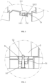
FIG. 3 is a sectional perspective view of a water tank according to the present disclosure. -
FIG. 4 is a sectional view of a water tank fitting with a drain valve according to the present disclosure. -
FIG. 5 is a sectional view of a floor-standing fan according to the present disclosure. -
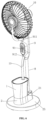
FIG. 6 is a perspective view of a floor-standing fan according to the present disclosure. -
FIG. 7 is an exploded perspective view of a floor-standing fan according to the present disclosure. -
FIG. 8 is a perspective view of a front box body of a floor-standing fan according to the present disclosure. -
FIG. 9 is a first perspective view of a rear box body of a floor-standing fan according to the present disclosure. -
FIG. 10 is a second perspective view of a rear box body of a floor-standing fan according to the present disclosure. - A detailed description is provided below of embodiments of the present disclosure, examples of which embodiments are shown in the accompanying drawings on which the same or similar designator are used for representing the same or similar elements or the elements having the same or similar functions. Those embodiments described below with reference to the accompanying drawings are exemplary, which are merely to illustrate the present disclosure and cannot be understood as a restriction to the present disclosure.
- As shown in
FIG. 1 ,FIG. 2 andFIG. 4 , a humidifier with improved control includes awater tank 1, abase 2, an ultrasonic high-frequency atomizing plate 3, afloat assembly 4, a drain valve 5 and a control panel (not shown in figures). Thebase 2 is provided thereon with an atomizingchamber 21 having an upper opening and an atomizing plate mounting base (not shown in figures) arranged on a bottom plate of the atomizingchamber 21. The drain valve 5 is arranged on a bottom plate of thewater tank 1, and thewater tank 1 detachably fits with the atomizingchamber 21. The bottom plate of the atomizingchamber 21 is further provided with asupport seat frame 22 and aspring seat hole 23. - The humidifier further includes a
guide seat plate 61, afloating frame 62, afloat block 63, a magnet (not shown in figures), a spring and amagnetic signal generator 64. - The
guide seat plate 61 is fixed on the support seat frame, the magnet is pre-embedded in thefloating block 63, and thefloating block 63 is fixed in thefloating frame 62. Thefloating frame 62 slidably fits with a guide hole on theguide seat plate 61 and move up and down, a lower end of the spring is arranged in thespring seat hole 23 while an upper end fits with a lower end of thefloating frame 62. A top of thefloating frame 62 fits with the bottom plate of thewater tank 1, and themagnetic signal generator 64 is arranged inside the atomizingchamber 21 and fits with the magnet. - The
magnetic signal generator 64 is a reed switch or a Hall sensor. - The top of the
floating frame 62 is provided with atransmission rod 621, and thetransmission rod 621 fits with the bottom plate of thewater tank 1. - When the
water tank 1 is fastened to the atomizingchamber 21 of thebase 2, the bottom plate of thewater tank 1 fits with thetransmission rod 621, the spring is compressed, and the magnet is staggered from themagnetic signal generator 64. When the water tank is separated from the base, thefloating frame 62 moves upward, the magnet is opposite to themagnetic signal generator 64, themagnetic signal generator 64 transmits a signal to the control panel, and the control panel powers off the ultrasonic high-frequency atomizing plate 3, whereby stopping operating. The safety is improved. - As shown in
FIG. 4 , the drain valve 5 includes avalve core 51, avalve rod 52, apressure spring 53 and avalve seat 54 arranged on the bottom plate of thewater tank 1. - The
valve seat 54 includes avalve chamber 541 having an upper opening and a waterguide seat plate 542 arranged on a lower part of the valve chamber, the waterguide seat plate 542 is formed thereon with aguide hole 5421 along an axial line and awater guide hole 5422 arranged surrounding the guide hole. - The
valve rod 52 passes through thepressure spring 53 and theguide hole 5421 to connect to thevalve core 51, and thevalve core 51 fits with an upper end of thevalve chamber 541. Thevalve rod 52 has a lower end provided with a circular seat plate which supports thepressure spring 53. - The
float assembly 4 drives thevalve rod 52 and the drain valve 5 to turn on. - The
float assembly 4 includes aseat body 41 and afloat 42. - The
seat body 41 is provided with a chamber body having an upper opening and a lateral opening, and a side wall plate at the lateral opening is formed with a half-shaft hole 411. - The
float 42 is provided with arotating seat 421, and the rotating seat is provided with half-shafts 422 on two sides thereof and a drivingrod 423 on a top thereof. - The
rotating seat 421 extends into the chamber body of theseat body 41 through the lateral opening, the half-shaft 422 rotatably fits with the half-shaft hole 411, and the drivingrod 423 fits with thevalve rod 52. When the water tank is fastened to thebase 1, the drivingrod 423 acts on thevalve rod 52, the water inside the water tank enters theatomizing chamber 21 of the base. When the water tank is removed from the base, under the action of thepressure spring 53, thevalve core 51 seals an upper end of thevalve chamber 541. - As shown in
FIG. 5 ,FIG. 6 andFIG. 7 , a floor-standing fan includes apedestal 7, avertical pipe 8, acontrol box 9, afan head 10, amist guide pipe 11 and the humidifier as described above. - The
base 2 is provided with avertical pipe seat 24, and thebase 2 extends toward the periphery in a circular direction to form apedestal shell 25 having a lower opening, and thepedestal 7 is embedded into thepedestal shell 25. Position relationships and connection relationships of other components have been disclosed in the Chinese patent entitled Top-added-water floor-standing humidifying fan. - As shown in
FIG. 5 ,FIG. 7 ,FIG. 8 ,FIG. 9 andFIG. 10 , a floor-standing fan includes apedestal 7, avertical pipe 8, acontrol box 9, afan head 10, amist guide pipe 11 and the humidifier according to any one ofclaims 1 to 5. Thecontrol box 9 includes afront box body 91 having a rear opening and arear box body 92 having a front opening. - The
front box body 91 having an upper part formed with a frontpipe outlet hole 911 and a lower part formed with a frontpipe inlet hole 912, therear box body 92 is formed with arecess 921 having a rear opening, and the recess having a lower part formed with a rearpipe outlet hole 922 and an upper part formed with a rearpipe inlet hole 923. - The
mist guide pipe 11 enters thecontrol box 9 through the frontpipe inlet hole 912, enters therecess 921 through the rearpipe outlet hole 922 and is embedded into therecess 921, enters thecontrol box 9 through the rearpipe inlet hole 923 and extends out of thecontrol box 9 through the frontpipe outlet hole 911, and then is connected to thefan head 10. With this structure, the length of themist guide pipe 11 above or below thecontrol box 9 can be adjusted. - Although the embodiments of the present disclosure are illustrated and described above, for the ordinary staff in this field, it is understandable that multiple changes, modifications, substitutions and variations may be made to these embodiments without departing from the principle and spirit of the present disclosure. The scope of the present disclosure is defined by the claims appended herein and equivalents thereof.
Claims (7)
- A humidifier with improved control, comprising a water tank, a base, an ultrasonic high-frequency atomizing plate, a float assembly, a drain valve and a control panel, the base being provided thereon with an atomizing chamber having an upper opening and an atomizing plate mounting base arranged on a bottom plate of the atomizing chamber, the drain valve being arranged on a bottom plate of the water tank, and the water tank detachably fits with the atomizing chamber, wherein the bottom plate of the atomizing chamber is further provided with a support seat frame and a spring seat hole;the humidifier further comprising a guide seat plate, a floating frame, a float block, a magnet, a spring and a magnetic signal generator, whereinthe guide seat plate is fixed on the support seat frame, the magnet is pre-embedded in the floating block, the floating block is fixed in the floating frame, the floating frame slidably fits with a guide hole on the guide seat plate, a lower end of the spring is arranged in the spring seat hole while an upper end fits with a lower end of the floating frame, a top of the floating frame fits with the bottom plate of the water tank, and the magnetic signal generator is arranged inside the atomizing chamber and fits with the magnet.
- The humidifier with improved control according to claim 1, wherein the magnetic signal generator is a reed switch or a Hall sensor.
- The humidifier with improved control according to claim 1, wherein the top of the floating frame is provided with a transmission rod, and the transmission rod fits with the bottom plate of the water tank.
- The humidifier with improved control according to claim 1, 2 or 3, wherein the drain valve comprises a valve core, a valve rod, a pressure spring and a valve seat arranged on the bottom plate of the water tank;the valve seat comprises a valve chamber having an upper opening and a water guide seat plate arranged on a lower part of the valve chamber, the water guide seat plate is formed thereon with a guide hole along an axial line and a water guide hole arranged surrounding the guide hole;the valve rod passes through the pressure spring and the guide hole to connect to the valve core, and the valve core fits with an upper end of the valve chamber; andthe float assembly drives the valve rod and the drain valve to turn on.
- The humidifier with improved control according to claim 4, wherein the float assembly comprises a seat body and a float;the seat body is provided with a chamber body having an upper opening and a lateral opening, and a side wall plate at the lateral opening is formed with a half-shaft hole;the float is provided with a rotating seat, and the rotating seat is provided with half-shafts on two sides thereof and a driving rod on a top thereof; andthe rotating seat extends into the seat body through the lateral opening, the half-shaft rotatably fits with the half-shaft hole, and the driving rod fits with the valve rod.
- A floor-standing fan, comprising a pedestal, a vertical pipe, a control box, a fan head, a mist guide pipe and the humidifier according to any one of claims 1 to 5, wherein
the base is provided with a vertical pipe seat, and the base extends toward the periphery in a circular direction to form a pedestal shell having a lower opening, and the pedestal is embedded into the pedestal shell. - A floor-standing fan, comprising a pedestal, a vertical pipe, a control box, a fan head, a mist guide pipe and the humidifier according to any one of claims 1 to 5, wherein the control box comprising a front box body having a rear opening and a rear box body having a front opening;the front box body having an upper part formed with a front pipe outlet hole and a lower part formed with a front pipe inlet hole, the rear box body is formed with a recess having a rear opening, and the recess having a lower part formed with a rear pipe outlet hole and an upper part formed with a rear pipe inlet hole;the mist guide pipe enters the control box through the front pipe inlet hole, enters the recess through the rear pipe outlet hole and is embedded into the recess, enters the control box through the rear pipe inlet hole and extends out of the control box through the front pipe outlet hole.
Applications Claiming Priority (1)
| Application Number | Priority Date | Filing Date | Title |
|---|---|---|---|
| CN202211430073.5A CN115899906A (en) | 2022-11-15 | 2022-11-15 | A humidifier and floor fan with improved control |
Publications (3)
| Publication Number | Publication Date |
|---|---|
| EP4372290A1 true EP4372290A1 (en) | 2024-05-22 |
| EP4372290B1 EP4372290B1 (en) | 2026-01-14 |
| EP4372290C0 EP4372290C0 (en) | 2026-01-14 |
Family
ID=86486405
Family Applications (1)
| Application Number | Title | Priority Date | Filing Date |
|---|---|---|---|
| EP23178384.6A Active EP4372290B1 (en) | 2022-11-15 | 2023-06-09 | Humidifier with improved control and floor-standing fan |
Country Status (3)
| Country | Link |
|---|---|
| US (1) | US12607375B2 (en) |
| EP (1) | EP4372290B1 (en) |
| CN (1) | CN115899906A (en) |
Families Citing this family (2)
| Publication number | Priority date | Publication date | Assignee | Title |
|---|---|---|---|---|
| CN115853801B (en) * | 2022-11-15 | 2026-05-12 | 中山市宏冠西联电气科技有限公司 | Floor fan with improved mist guide pipe fixation |
| USD1093594S1 (en) * | 2023-01-05 | 2025-09-16 | Zhongshan Hongguan West Union E-Tech Co., Ltd | Floor fan |
Citations (7)
| Publication number | Priority date | Publication date | Assignee | Title |
|---|---|---|---|---|
| CN101149174A (en) * | 2007-10-24 | 2008-03-26 | 美的集团有限公司 | ultrasonic humidifier |
| CN102374617A (en) * | 2010-08-26 | 2012-03-14 | 珠海格力电器股份有限公司 | Power-off protection device for humidifier |
| WO2019037377A1 (en) * | 2017-08-21 | 2019-02-28 | 深圳前海帕拓逊网络技术有限公司 | Humidifier having power cut off protection function |
| CN111023307A (en) * | 2019-12-31 | 2020-04-17 | 宁波奥克斯电气股份有限公司 | A humidifier and an air conditioner |
| CN111156638A (en) * | 2020-02-14 | 2020-05-15 | 佛山市顺德区巨科电器有限公司 | Humidifier with automatic water adding and power off functions |
| CN112746982A (en) * | 2021-01-20 | 2021-05-04 | 中山市宏冠西联电气科技有限公司 | Floor fan with humidifying device |
| CN214746166U (en) * | 2021-02-05 | 2021-11-16 | 中山市宏冠西联电气科技有限公司 | Floor fan with upper water adding and humidifying functions |
Family Cites Families (8)
| Publication number | Priority date | Publication date | Assignee | Title |
|---|---|---|---|---|
| EP2414738B1 (en) * | 2009-03-04 | 2013-10-09 | Dyson Technology Limited | Humidifying apparatus |
| CN201874857U (en) * | 2010-11-29 | 2011-06-22 | 李玉营 | Energy-saving and efficient frequency conversion cooling floor fan |
| CN203083660U (en) * | 2013-01-28 | 2013-07-24 | 卢生成 | Water level induction structure of humidifier |
| CN206247535U (en) * | 2016-10-24 | 2017-06-13 | 廖湘娜 | A kind of upper water-adding humidifier with cistern water level alarm set |
| CN210583204U (en) * | 2018-12-21 | 2020-05-22 | 佛山市南海科日超声电子有限公司 | New Aroma Diffuser |
| CN211011761U (en) * | 2019-10-16 | 2020-07-14 | 中山市大毅电器科技有限公司 | Launching device and water vapor atomization generator |
| CN215930031U (en) * | 2021-09-14 | 2022-03-01 | 深圳纳优达电子制造有限公司 | Water level float valve structure for humidifier water tank lifting and stopping |
| CN114719364A (en) * | 2022-03-31 | 2022-07-08 | 北京小米移动软件有限公司 | Humidifier |
-
2022
- 2022-11-15 CN CN202211430073.5A patent/CN115899906A/en active Pending
-
2023
- 2023-06-08 US US18/207,326 patent/US12607375B2/en active Active
- 2023-06-09 EP EP23178384.6A patent/EP4372290B1/en active Active
Patent Citations (7)
| Publication number | Priority date | Publication date | Assignee | Title |
|---|---|---|---|---|
| CN101149174A (en) * | 2007-10-24 | 2008-03-26 | 美的集团有限公司 | ultrasonic humidifier |
| CN102374617A (en) * | 2010-08-26 | 2012-03-14 | 珠海格力电器股份有限公司 | Power-off protection device for humidifier |
| WO2019037377A1 (en) * | 2017-08-21 | 2019-02-28 | 深圳前海帕拓逊网络技术有限公司 | Humidifier having power cut off protection function |
| CN111023307A (en) * | 2019-12-31 | 2020-04-17 | 宁波奥克斯电气股份有限公司 | A humidifier and an air conditioner |
| CN111156638A (en) * | 2020-02-14 | 2020-05-15 | 佛山市顺德区巨科电器有限公司 | Humidifier with automatic water adding and power off functions |
| CN112746982A (en) * | 2021-01-20 | 2021-05-04 | 中山市宏冠西联电气科技有限公司 | Floor fan with humidifying device |
| CN214746166U (en) * | 2021-02-05 | 2021-11-16 | 中山市宏冠西联电气科技有限公司 | Floor fan with upper water adding and humidifying functions |
Also Published As
| Publication number | Publication date |
|---|---|
| US12607375B2 (en) | 2026-04-21 |
| EP4372290B1 (en) | 2026-01-14 |
| US20240159408A1 (en) | 2024-05-16 |
| CN115899906A (en) | 2023-04-04 |
| EP4372290C0 (en) | 2026-01-14 |
Similar Documents
| Publication | Publication Date | Title |
|---|---|---|
| US12607375B2 (en) | Humidifier with improved control and floor-standing fan | |
| US10962244B2 (en) | Humidifier | |
| CN101149174A (en) | ultrasonic humidifier | |
| KR102457136B1 (en) | apparatus for both humidification and air cleaning | |
| CN112032848B (en) | Air treatment device and air conditioner | |
| CN220506841U (en) | Lifting type range hood | |
| CN110345078B (en) | Forced-ventilated pump structure and cleaning machine applying same | |
| KR102010974B1 (en) | Humidifier | |
| CN216555619U (en) | Steam control valve and steam valve body structure thereof | |
| CN217685420U (en) | Air conditioner indoor unit and air conditioner | |
| CN210832215U (en) | Wall-mounted air conditioner indoor unit | |
| CN210769547U (en) | Spherical fan with regulatory function | |
| CN219300925U (en) | Magnetic induction control humidifier | |
| CN210664005U (en) | Phase change spray cooling tower capable of improving cooling amplitude | |
| CN221034144U (en) | Aeration valve | |
| CN218765816U (en) | Water leakage detection device for underwater robot | |
| CN218031456U (en) | Intelligent switch butterfly valve | |
| CN213597137U (en) | Upper water outlet and inlet valve for toilet cistern | |
| CN220750359U (en) | Column cabinet type air conditioner air inlet grille | |
| CN219965241U (en) | Novel pneumatic spray head | |
| CN106015691B (en) | Valve driving device based on interior lifting shut-off valve | |
| CN223907595U (en) | Floating ball anti-interference device for water tank | |
| CN220648446U (en) | An air conditioner indoor unit | |
| CN223165661U (en) | Water-isolation mute type evaporation humidifier | |
| CN219396930U (en) | Lid subassembly and have its cooking utensil |
Legal Events
| Date | Code | Title | Description |
|---|---|---|---|
| PUAI | Public reference made under article 153(3) epc to a published international application that has entered the european phase |
Free format text: ORIGINAL CODE: 0009012 |
|
| STAA | Information on the status of an ep patent application or granted ep patent |
Free format text: STATUS: THE APPLICATION HAS BEEN PUBLISHED |
|
| AK | Designated contracting states |
Kind code of ref document: A1 Designated state(s): AL AT BE BG CH CY CZ DE DK EE ES FI FR GB GR HR HU IE IS IT LI LT LU LV MC ME MK MT NL NO PL PT RO RS SE SI SK SM TR |
|
| STAA | Information on the status of an ep patent application or granted ep patent |
Free format text: STATUS: REQUEST FOR EXAMINATION WAS MADE |
|
| 17P | Request for examination filed |
Effective date: 20240604 |
|
| RBV | Designated contracting states (corrected) |
Designated state(s): AL AT BE BG CH CY CZ DE DK EE ES FI FR GB GR HR HU IE IS IT LI LT LU LV MC ME MK MT NL NO PL PT RO RS SE SI SK SM TR |
|
| GRAP | Despatch of communication of intention to grant a patent |
Free format text: ORIGINAL CODE: EPIDOSNIGR1 |
|
| STAA | Information on the status of an ep patent application or granted ep patent |
Free format text: STATUS: GRANT OF PATENT IS INTENDED |
|
| INTG | Intention to grant announced |
Effective date: 20251001 |
|
| GRAS | Grant fee paid |
Free format text: ORIGINAL CODE: EPIDOSNIGR3 |
|
| GRAA | (expected) grant |
Free format text: ORIGINAL CODE: 0009210 |
|
| STAA | Information on the status of an ep patent application or granted ep patent |
Free format text: STATUS: THE PATENT HAS BEEN GRANTED |
|
| AK | Designated contracting states |
Kind code of ref document: B1 Designated state(s): AL AT BE BG CH CY CZ DE DK EE ES FI FR GB GR HR HU IE IS IT LI LT LU LV MC ME MK MT NL NO PL PT RO RS SE SI SK SM TR |
|
| REG | Reference to a national code |
Ref country code: CH Ref legal event code: F10 Free format text: ST27 STATUS EVENT CODE: U-0-0-F10-F00 (AS PROVIDED BY THE NATIONAL OFFICE) Effective date: 20260114 Ref country code: GB Ref legal event code: FG4D |
|
| REG | Reference to a national code |
Ref country code: DE Ref legal event code: R096 Ref document number: 602023010640 Country of ref document: DE |
|
| REG | Reference to a national code |
Ref country code: IE Ref legal event code: FG4D |
|
| U01 | Request for unitary effect filed |
Effective date: 20260206 |
|
| U07 | Unitary effect registered |
Designated state(s): AT BE BG DE DK EE FI FR IT LT LU LV MT NL PT RO SE SI Effective date: 20260212 |
|
| PG25 | Lapsed in a contracting state [announced via postgrant information from national office to epo] |
Ref country code: RS Free format text: LAPSE BECAUSE OF FAILURE TO SUBMIT A TRANSLATION OF THE DESCRIPTION OR TO PAY THE FEE WITHIN THE PRESCRIBED TIME-LIMIT Effective date: 20260414 |
|
| PG25 | Lapsed in a contracting state [announced via postgrant information from national office to epo] |
Ref country code: ES Free format text: LAPSE BECAUSE OF FAILURE TO SUBMIT A TRANSLATION OF THE DESCRIPTION OR TO PAY THE FEE WITHIN THE PRESCRIBED TIME-LIMIT Effective date: 20260114 |
|
| PG25 | Lapsed in a contracting state [announced via postgrant information from national office to epo] |
Ref country code: PL Free format text: LAPSE BECAUSE OF FAILURE TO SUBMIT A TRANSLATION OF THE DESCRIPTION OR TO PAY THE FEE WITHIN THE PRESCRIBED TIME-LIMIT Effective date: 20260114 |
|
| PG25 | Lapsed in a contracting state [announced via postgrant information from national office to epo] |
Ref country code: GR Free format text: LAPSE BECAUSE OF FAILURE TO SUBMIT A TRANSLATION OF THE DESCRIPTION OR TO PAY THE FEE WITHIN THE PRESCRIBED TIME-LIMIT Effective date: 20260415 |
|
| PG25 | Lapsed in a contracting state [announced via postgrant information from national office to epo] |
Ref country code: NO Free format text: LAPSE BECAUSE OF FAILURE TO SUBMIT A TRANSLATION OF THE DESCRIPTION OR TO PAY THE FEE WITHIN THE PRESCRIBED TIME-LIMIT Effective date: 20260414 |
|
| PG25 | Lapsed in a contracting state [announced via postgrant information from national office to epo] |
Ref country code: HR Free format text: LAPSE BECAUSE OF FAILURE TO SUBMIT A TRANSLATION OF THE DESCRIPTION OR TO PAY THE FEE WITHIN THE PRESCRIBED TIME-LIMIT Effective date: 20260114 |
|
| PG25 | Lapsed in a contracting state [announced via postgrant information from national office to epo] |
Ref country code: IS Free format text: LAPSE BECAUSE OF FAILURE TO SUBMIT A TRANSLATION OF THE DESCRIPTION OR TO PAY THE FEE WITHIN THE PRESCRIBED TIME-LIMIT Effective date: 20260514 |
|
| U20 | Renewal fee for the european patent with unitary effect paid |
Year of fee payment: 4 Effective date: 20260617 |