EP4372258A1 - Electric valve - Google Patents
Electric valve Download PDFInfo
- Publication number
- EP4372258A1 EP4372258A1 EP22841924.8A EP22841924A EP4372258A1 EP 4372258 A1 EP4372258 A1 EP 4372258A1 EP 22841924 A EP22841924 A EP 22841924A EP 4372258 A1 EP4372258 A1 EP 4372258A1
- Authority
- EP
- European Patent Office
- Prior art keywords
- valve
- pulse
- valve member
- angle
- section
- Prior art date
- Legal status (The legal status is an assumption and is not a legal conclusion. Google has not performed a legal analysis and makes no representation as to the accuracy of the status listed.)
- Pending
Links
Images







Classifications
-
- F—MECHANICAL ENGINEERING; LIGHTING; HEATING; WEAPONS; BLASTING
- F16—ENGINEERING ELEMENTS AND UNITS; GENERAL MEASURES FOR PRODUCING AND MAINTAINING EFFECTIVE FUNCTIONING OF MACHINES OR INSTALLATIONS; THERMAL INSULATION IN GENERAL
- F16K—VALVES; TAPS; COCKS; ACTUATING-FLOATS; DEVICES FOR VENTING OR AERATING
- F16K31/00—Actuating devices; Operating means; Releasing devices
- F16K31/02—Actuating devices; Operating means; Releasing devices electric; magnetic
- F16K31/04—Actuating devices; Operating means; Releasing devices electric; magnetic using a motor
- F16K31/046—Actuating devices; Operating means; Releasing devices electric; magnetic using a motor with electric means, e.g. electric switches, to control the motor or to control a clutch between the valve and the motor
-
- F—MECHANICAL ENGINEERING; LIGHTING; HEATING; WEAPONS; BLASTING
- F16—ENGINEERING ELEMENTS AND UNITS; GENERAL MEASURES FOR PRODUCING AND MAINTAINING EFFECTIVE FUNCTIONING OF MACHINES OR INSTALLATIONS; THERMAL INSULATION IN GENERAL
- F16K—VALVES; TAPS; COCKS; ACTUATING-FLOATS; DEVICES FOR VENTING OR AERATING
- F16K31/00—Actuating devices; Operating means; Releasing devices
- F16K31/02—Actuating devices; Operating means; Releasing devices electric; magnetic
- F16K31/04—Actuating devices; Operating means; Releasing devices electric; magnetic using a motor
- F16K31/041—Actuating devices; Operating means; Releasing devices electric; magnetic using a motor for rotating valves
-
- F—MECHANICAL ENGINEERING; LIGHTING; HEATING; WEAPONS; BLASTING
- F16—ENGINEERING ELEMENTS AND UNITS; GENERAL MEASURES FOR PRODUCING AND MAINTAINING EFFECTIVE FUNCTIONING OF MACHINES OR INSTALLATIONS; THERMAL INSULATION IN GENERAL
- F16K—VALVES; TAPS; COCKS; ACTUATING-FLOATS; DEVICES FOR VENTING OR AERATING
- F16K1/00—Lift valves or globe valves, i.e. cut-off apparatus with closure members having at least a component of their opening and closing motion perpendicular to the closing faces
- F16K1/02—Lift valves or globe valves, i.e. cut-off apparatus with closure members having at least a component of their opening and closing motion perpendicular to the closing faces with screw-spindle
-
- F—MECHANICAL ENGINEERING; LIGHTING; HEATING; WEAPONS; BLASTING
- F16—ENGINEERING ELEMENTS AND UNITS; GENERAL MEASURES FOR PRODUCING AND MAINTAINING EFFECTIVE FUNCTIONING OF MACHINES OR INSTALLATIONS; THERMAL INSULATION IN GENERAL
- F16K—VALVES; TAPS; COCKS; ACTUATING-FLOATS; DEVICES FOR VENTING OR AERATING
- F16K1/00—Lift valves or globe valves, i.e. cut-off apparatus with closure members having at least a component of their opening and closing motion perpendicular to the closing faces
- F16K1/32—Details
- F16K1/54—Arrangements for modifying the way in which the rate of flow varies during the actuation of the valve
-
- F—MECHANICAL ENGINEERING; LIGHTING; HEATING; WEAPONS; BLASTING
- F16—ENGINEERING ELEMENTS AND UNITS; GENERAL MEASURES FOR PRODUCING AND MAINTAINING EFFECTIVE FUNCTIONING OF MACHINES OR INSTALLATIONS; THERMAL INSULATION IN GENERAL
- F16K—VALVES; TAPS; COCKS; ACTUATING-FLOATS; DEVICES FOR VENTING OR AERATING
- F16K31/00—Actuating devices; Operating means; Releasing devices
- F16K31/44—Mechanical actuating means
- F16K31/46—Mechanical actuating means for remote operation
-
- F—MECHANICAL ENGINEERING; LIGHTING; HEATING; WEAPONS; BLASTING
- F16—ENGINEERING ELEMENTS AND UNITS; GENERAL MEASURES FOR PRODUCING AND MAINTAINING EFFECTIVE FUNCTIONING OF MACHINES OR INSTALLATIONS; THERMAL INSULATION IN GENERAL
- F16K—VALVES; TAPS; COCKS; ACTUATING-FLOATS; DEVICES FOR VENTING OR AERATING
- F16K37/00—Special means in or on valves or other cut-off apparatus for indicating or recording operation thereof, or for enabling an alarm to be given
- F16K37/0025—Electrical or magnetic means
- F16K37/0041—Electrical or magnetic means for measuring valve parameters
-
- H—ELECTRICITY
- H02—GENERATION; CONVERSION OR DISTRIBUTION OF ELECTRIC POWER
- H02P—CONTROL OR REGULATION OF ELECTRIC MOTORS, ELECTRIC GENERATORS OR DYNAMO-ELECTRIC CONVERTERS; CONTROLLING TRANSFORMERS, REACTORS OR CHOKE COILS
- H02P8/00—Arrangements for controlling dynamo-electric motors rotating step by step
- H02P8/22—Control of step size; Intermediate stepping, e.g. microstepping
-
- F—MECHANICAL ENGINEERING; LIGHTING; HEATING; WEAPONS; BLASTING
- F16—ENGINEERING ELEMENTS AND UNITS; GENERAL MEASURES FOR PRODUCING AND MAINTAINING EFFECTIVE FUNCTIONING OF MACHINES OR INSTALLATIONS; THERMAL INSULATION IN GENERAL
- F16K—VALVES; TAPS; COCKS; ACTUATING-FLOATS; DEVICES FOR VENTING OR AERATING
- F16K31/00—Actuating devices; Operating means; Releasing devices
- F16K31/44—Mechanical actuating means
- F16K31/50—Mechanical actuating means with screw-spindle or internally threaded actuating means
- F16K31/504—Mechanical actuating means with screw-spindle or internally threaded actuating means the actuating means being rotable, rising, and having internal threads which co-operate with threads on the outside of the valve body
-
- Y—GENERAL TAGGING OF NEW TECHNOLOGICAL DEVELOPMENTS; GENERAL TAGGING OF CROSS-SECTIONAL TECHNOLOGIES SPANNING OVER SEVERAL SECTIONS OF THE IPC; TECHNICAL SUBJECTS COVERED BY FORMER USPC CROSS-REFERENCE ART COLLECTIONS [XRACs] AND DIGESTS
- Y02—TECHNOLOGIES OR APPLICATIONS FOR MITIGATION OR ADAPTATION AGAINST CLIMATE CHANGE
- Y02B—CLIMATE CHANGE MITIGATION TECHNOLOGIES RELATED TO BUILDINGS, e.g. HOUSING, HOUSE APPLIANCES OR RELATED END-USER APPLICATIONS
- Y02B30/00—Energy efficient heating, ventilation or air conditioning [HVAC]
- Y02B30/70—Efficient control or regulation technologies, e.g. for control of refrigerant flow, motor or heating
Definitions
- the present invention relates to an electric valve that is used in, for example, a refrigeration cycle system of an air-conditioning apparatus.
- Patent Literature 1 discloses an electric valve of the related art.
- the electric valve described in Patent Literature 1 includes a valve member and a stepping motor.
- the valve member faces a valve port.
- the valve member is moved, as a result of rotation of the stepping motor, in a direction in which the valve member faces the valve port.
- Patent Literature 1 Japanese Unexamined Patent Application Publication No. 8-268030
- the stepping motor rotates in response to pulses.
- the rotation angle (the step angle) per pulse of the stepping motor is constant, and the amount of movement of the valve member per pulse is also constant.
- the flow-rate characteristics of the electric valve depend on the shape of the valve member. In order to obtain desired flow-rate characteristics, it is necessary to use a valve member that has a shape corresponding to the flow-rate characteristics.
- an object of the present invention is to provide an electric valve capable of obtaining desired flow-rate characteristics without depending on the shape of a valve member.
- an electric valve includes a valve body that has a valve port, a valve member that faces the valve port, a driving mechanism that moves the valve member in a direction in which the valve member faces the valve port, and a control device that controls the driving mechanism.
- the driving mechanism includes a stepping motor, and rotation of the stepping motor causes the valve member to move.
- a first section, a second section, and a third section be set between the reference position of the valve member and the full-open position of the valve member. It is preferable that a first angle be set as the step angle corresponding to the pulse numbers assigned to the first section. It is preferable that a second angle be set as the step angle corresponding to the pulse numbers assigned to the second section. It is preferable that a third angle be set as the step angle corresponding to the pulse numbers assigned to the third section. It is preferable that the first angle, the second angle, and the third angle be different from one another.
- the first angle be a step angle in a micro-step operation that is 1/n of a step angle in a full-step operation of the stepping motor.
- the second angle be a step angle in a micro-step operation that is 1/m of the step angle in the full-step operation of the stepping motor.
- the third angle be the step angle in the full-step operation of the stepping motor. Note that m and n are each a natural number of two or more, with a condition that m ⁇ n.
- the valve member have a tapered surface such that a diameter of the valve member decreases toward the valve port. It is preferable that, when the valve member is in the first section, the second section, or the third section, a flow rate be determined by a gap between the tapered surface and an inner circumferential surface of the valve port.
- a pulse rate when the valve member is in the first section be n times a pulse rate when the valve member is in the third section. It is preferable that a pulse rate when the valve member is in the second section be m times the pulse rate when the valve member is in the third section.
- a first section and a second section be set between the reference position of the valve member and the full-open position of the valve member. It is preferable that a first angle be set as the step angle corresponding to the pulse numbers assigned to the first section. It is preferable that a second angle be set as the step angle corresponding to the pulse numbers assigned to the second section. It is preferable that the first angle and the second angle be different from each other.
- the first angle be a step angle in a micro-step operation that is 1/n of a step angle in a full-step operation of the stepping motor. It is preferable that the second angle be the step angle in the full-step operation of the stepping motor. Note that n is a natural number of two or more.
- the valve member have a tapered surface such that a diameter of the valve member decreases toward the valve port. It is preferable that, when the valve member is in the first section or the second section, a flow rate be determined by a gap between the tapered surface and an inner circumferential surface of the valve port.
- a pulse rate when the valve member is in the first section be n times a pulse rate when the valve member is in the second section.
- the storage unit store start-up-state pulse-number information and start-up-state step-angle information, the start-up-state pulse-number information relating to pulse numbers that are sequentially assigned from the reference position of the valve member to the full-open position of the valve member, and the start-up-state step-angle information relating to step angles each of which corresponds to one of the pulse numbers of the start-up-state pulse-number information.
- the storage unit store normal-operating-state pulse-number information and normal-operating-state step-angle information, the normal-operating-state pulse-number information relating to pulse numbers that are sequentially assigned from the reference position of the valve member to the full-open position of the valve member, and the normal-operating-state step-angle information relating to step angles each of which corresponds to one of the pulse numbers of the normal-operating-state pulse-number information.
- control device use, in a start-up state, the start-up-state pulse-number information and the start-up-state step-angle information as the pulse number information and the step angle information and use, in a normal operating state after transitioning from the start-up state, the normal-operating-state pulse-number information and the normal-operating-state step-angle information as the pulse number information and the step angle information.
- the control device make a transition to the normal operating state.
- the control device make a transition to the normal operating state.
- the control device of the electric valve stores the pulse number information relating to the pulse numbers that are sequentially assigned from the reference position of the valve member to the full-open position of the valve member and the step angle information relating to the step angles each of which corresponds to one of the pulse numbers.
- the control device receives the valve-member movement command relating to the moving target position of the valve member from the external device.
- the control device acquires the pulse numbers assigned from the present position of the valve member to the moving target position.
- the control device rotates the stepping motor at the step angles corresponding to the pulse numbers assigned from the present position of the valve member to the moving target position in the order of these pulse numbers.
- the electric valve can individually set a step angle for each pulse assigned from the reference position of the valve member to the full-open position and can adjust the amount of movement of the valve member per pulse (i.e., the amount of change in the flow rate of a refrigerant flowing through a valve port). Therefore, in the electric valve, desired flow-rate characteristics can be obtained without depending on the shape of a valve member.
- Fig. 1 is a sectional view of the electric valve according to the embodiment of the present invention.
- Fig. 2 is a sectional view of a stator unit of the electric valve illustrated in Fig. 1 .
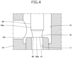
- Fig. 3 and Fig. 4 are each an enlarged sectional view of a valve member and members in its vicinity that are included in the electric valve illustrated in Fig. 1 .
- Fig. 3 illustrates a state where the valve member is located at a valve closing position.
- Fig. 4 illustrates a state where the valve member is located at a full-open position.
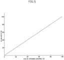
- Fig. 5 is a graph illustrating a relationship between valve opening degree and flow rate in the electric valve illustrated in Fig. 1 .
- Fig. 1 is a sectional view of the electric valve according to the embodiment of the present invention.
- Fig. 2 is a sectional view of a stator unit of the electric valve illustrated in Fig. 1 .
- Fig. 3 and Fig. 4 are each an enlarged sectional view
- FIG. 6 is a diagram illustrating a positional relationship between a magnet rotor and a stator that are included in the electric valve illustrated in Fig. 1 .
- Fig. 6A illustrates a state where magnetic poles of the magnet rotor and pole teeth of an A-phase stator face each other.
- Fig. 6B illustrates a state where the magnetic poles of the magnet rotor and pole teeth of a B-phase stator face each other.
- Fig. 7 is a functional block diagram of the electric valve illustrated in Fig. 1 .
- Fig. 8 is a diagram illustrating a table relating to pulse number information and step angle information that are stored in a control device of the electric valve illustrated in Fig. 1 .
- Fig. 9 is a diagram illustrating a relationship between each pulse number and a position of the valve member, each of the pulse numbers being shown in the table in Fig. 8 and being assigned from the valve closing position to the full-open position.
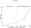
- Fig. 10 is a graph illustrating a relationship between the position of the valve member and the flow rate when a stepping motor of the electric valve illustrated in Fig. 1 rotates on the basis of the table illustrated in Fig. 8 .
- the electric valve 1 includes a valve body 10, a can 20, a driving mechanism 30, and a valve member 40.
- the valve body 10 is made of a metal such as an aluminum alloy.
- the valve body 10 includes a body member 11, a supporting member 12, and a connecting member 13.
- the body member 11 has a rectangular parallelepiped shape.
- the body member 11 includes a valve chamber 14 and flow channels 15 and 16.
- the flow channel 15 is connected to the valve chamber 14.
- the flow channel 16 is connected to the valve chamber 14 via a valve port 17.
- the valve port 17 is enclosed by a valve seat 18 that has a circular annular shape.
- a mounting hole 11a is formed in an upper surface of the body member 11 so as to communicate with the valve chamber 14.
- the supporting member 12 has a circular cylindrical shape.
- the supporting member 12 is attached to the mounting hole 11a of the body member 11 by using a screw structure.
- An upper portion of the supporting member 12 projects from the upper surface of the body member 11.
- the connecting member 13 has a circular annular plate-like shape. The inner circumferential edge of the connecting member 13 is joined to an upper end of the supporting member 12.
- the can 20 is made of a metal such as a stainless steel.
- the can 20 has a circular cylindrical shape whose lower end is open and whose upper end is closed. The lower end of the can 20 is joined to an outer circumferential edge of the connecting member 13.
- the driving mechanism 30 causes the valve member 40 to move in the vertical direction (a direction in which an axis L extends).
- the driving mechanism 30 includes a magnet rotor 31, a valve stem holder 32, a guide bush 33, a valve stem 34, a permanent magnet 38, and a stator unit 50.
- the magnet rotor 31 has a circular cylindrical shape.
- the outer diameter of the magnet rotor 31 is slightly smaller than the inner diameter of the can 20.
- the magnet rotor 31 has a plurality of N-poles and a plurality of S-poles.
- the plurality of N-poles and the plurality of S-poles are arranged at the outer circumferential surface of the magnet rotor 31.
- the plurality of N-poles and the plurality of S-poles each extend in the vertical direction.
- the plurality of N-poles and the plurality of S-poles are alternately arranged at equal angular intervals in a circumferential direction.
- the magnet rotor 31 has 12 N-poles and 12 S-poles.
- the angle between each of the N-poles and the adjacent S-pole is 15 degrees.
- the valve stem holder 32 has a circular cylindrical shape whose lower end is open and whose upper end is closed.
- a supporting ring 35 is fixed to an upper end of the valve stem holder 32.
- the supporting ring 35 connects the magnet rotor 31 and the valve stem holder 32 to each other.
- An internal thread 32c is formed in the inner circumferential surface of the valve stem holder 32.
- the guide bush 33 includes a base portion 33a and a valve-stem supporting portion 33b.
- the base portion 33a and the valve-stem supporting portion 33b each have a circular cylindrical shape.
- the base portion 33a is press-fitted into a fitting hole 12a that is formed in the supporting member 12.
- the outer diameter of the valve-stem supporting portion 33b is smaller than the outer diameter of the base portion 33a.
- the inner diameter of the valve-stem supporting portion 33b is the same as the inner diameter of the base portion 33a.
- the valve-stem supporting portion 33b is coaxially connected to an upper end of the base portion 33a.
- An external thread 33c is formed on the outer circumferential surface of the valve-stem supporting portion 33b. The external thread 33c is screwed into the internal thread 32c of the valve stem holder 32.
- the guide bush 33 is connected to the supporting member 12.
- the valve stem 34 includes a large-diameter portion 34a and a small-diameter portion 34b.
- the large-diameter portion 34a and the small-diameter portion 34b each has a circular columnar shape.
- the outer diameter of the large-diameter portion 34a is slightly smaller than the inner diameter of the guide bush 33.
- the outer diameter of the small-diameter portion 34b is smaller than the outer diameter of the large-diameter portion 34a.
- the small-diameter portion 34b is coaxially connected to an upper end of the large-diameter portion 34a.
- the small-diameter portion 34b extends through the valve stem holder 32.
- a push nut 36 for retaining is attached to the small-diameter portion 34b.
- the valve stem 34 is positioned inside the guide bush 33 and inside the supporting member 12.
- the valve stem 34 is supported by the guide bush 33 so as to be slidable in the vertical direction.
- a lower end of the valve stem 34 is positioned in the valve chamber 14.
- the valve stem 34 includes a step portion 34c between the large-diameter portion 34a and the small-diameter portion 34b.
- the step portion 34c is a circular annular flat surface that faces upward.
- a valve closing spring 37 is disposed between the valve stem holder 32 and the step portion 34c.
- the valve closing spring 37 is a compression-coil spring. The valve closing spring 37 presses the valve stem 34 downward.
- the permanent magnet 38 is disposed above the magnet rotor 31 inside the can 20.
- the permanent magnet 38 has a circular annular, flat plate-like shape.
- the permanent magnet 38 has a single N-pole and a single S-pole. When the permanent magnet 38 is divided into two portions by its diameter, the N-pole is located at one of the portions, and the S-pole is located at the other portion.
- the permanent magnet 38 is fixed to the supporting ring 35 with a fixing member 39 interposed therebetween. The permanent magnet 38 is rotated together with the magnet rotor 31.
- the valve member 40 is integrally connected to a lower end of the large-diameter portion 34a of the valve stem 34.
- the valve member 40 is disposed in the valve chamber 14.
- the valve member 40 faces the valve port 17 in the vertical direction.
- the valve member 40 has a tapered surface 41 such that its diameter gradually decreases toward the valve port 17.
- the tapered surface 41 extends in the axis L direction from a position near the lower end of the large-diameter portion 34a of the valve stem 34 to a tip end 40a of the valve member 40.
- the vertical direction is the same as the directions in which the valve member 40 and the valve port 17 face each other.
- the valve member 40 may have a plurality of tapered surfaces having different taper angles.
- the valve member 40 is moved in the vertical direction by the driving mechanism 30.
- the valve port 17 is opened and closed by the movement of the valve element 40.
- the valve member 40 is moved from a valve closing position P1 ( Fig. 3 ) to a full-open position P2 ( Fig. 4 ).
- the valve closing position P1 is a position of the valve member 40 at which the tapered surface 41 is in contact with the valve seat 18.
- the valve closing position P1 is a reference position.
- the full-open position P2 is a position of the valve member 40 at which the position of the tip end 40a of the valve member 40 in the vertical direction is the same as the position of the valve seat 18 in the vertical direction.
- the flow rate of refrigerant that flows through the valve port 17 depends on the size of a circular annular gap formed between the tapered surface 41 and the inner circumferential surface of the valve port 17.
- the graph illustrated in Fig. 5 shows the relationship between the valve opening degree and the flow rate in the electric valve 1.
- the valve opening degree corresponds to the position of the valve member 40 with respect to the valve seat 18 (the amount by which the valve member 40 is lifted from the valve closed position P1).
- the valve opening degree is expressed as a percentage.
- the valve opening degree is 0%, and when the valve member 40 is at the full-open position P2, the valve opening degree is 100%.
- the flow rate is the flow rate of the refrigerant that flows through the electric valve 1 (the valve port 17). The flow rate is expressed as a percentage.
- a basic flow-rate characteristic of the electric valve 1 (the valve member 40) is a linear characteristic in which the flow rate linearly changes in proportion to the valve opening degree.
- the valve member 40 may have, for example, a shape with which its basic flow-rate characteristic is an equal-percentage characteristic.
- the stator unit 50 includes a stator 60, a housing 70, a case 80, a main circuit board 90, a sub circuit board 100, a magnetic sensor 110, and a microcomputer 120.
- the stator 60 has a circular cylindrical shape.
- the stator 60 includes an A-phase stator 61, a B-phase stator 62, and a molded member 63 that is made of a synthetic resin.
- the A-phase stator 61 includes a plurality of claw-pole type pole teeth 61a and 61b arranged on its inner circumferential side. The ends of the pole teeth 61a face downward, and the ends of the pole teeth 61b face upward. The pole teeth 61a and the pole teeth 61b are alternately arranged at equal angular intervals in the circumferential direction.
- the A-phase stator 61 includes 12 pole teeth 61a and 12 pole teeth 61b. The angle between each of the pole teeth 61a and the adjacent pole tooth 61b is 15 degrees. When a coil 61c of the A-phase stator 61 is energized, the pole teeth 61a and the pole teeth 61b have mutually opposite polarities.
- the B-phase stator 62 includes a plurality of claw-pole type pole teeth 62a and 62b arranged on its inner circumferential side. The ends of the pole teeth 62a face downward, and the ends of the pole teeth 62b face upward. The pole teeth 62a and the pole teeth 62b are alternately arranged at equal angular intervals in the circumferential direction.
- the B-phase stator 62 includes 12 pole teeth 62a and 12 pole teeth 62b. The angle between each of the pole teeth 62a and the adjacent pole tooth 62b is 15 degrees. When a coil 62c of the B-phase stator 62 is energized, the pole teeth 62a and the pole teeth 62b have mutually opposite polarities.
- the A-phase stator 61 and the B-phase stator 62 are arranged so as to be coaxial with each other.
- the A-phase stator 61 and the B-phase stator 62 are in contact with each other.
- the angle between each of the pole teeth 61a of the A-phase stator 61 and the adjacent pole tooth 62a of the B-phase stator 62 is 7.5 degrees.
- the A-phase stator 61 and the B-phase stator 62 are filled with the molded member 63.
- the molded member 63 forms, together with the pole teeth 61a and 61b and the pole teeth 62a and 62b, a stator inner circumferential surface 60a.
- the diameter of the stator inner circumferential surface 60a is the same as the diameter of the outer circumferential surface of the can 20.
- the molded member 63 includes a terminal supporting portion 64.
- the terminal supporting portion 64 extends in the lateral direction (a direction perpendicular to the axis L) from the A-phase stator 61 and the B-phase stator 62.
- the terminal supporting portion 64 supports a plurality of terminals 65. Each of the plurality of terminals 65 projects in the lateral direction from an end of the terminal supporting portion 64.
- the plurality of terminals 65 are connected to the coil 61c of the A-phase stator 61 and the coil 62c of the B-phase stator 62.
- the can 20 is disposed inside the stator 60.
- the magnet rotor 31 is disposed inside the can 20.
- the stator 60 and the magnet rotor 31 constitute a stepping motor 66.
- the stepping motor 66 is capable of performing a full-step operation and a micro-step operation.
- the full-step operation is an operation that causes the magnet rotor 31 to rotate, in response to a single pulse input, from a position (the position illustrated in Fig. 6A ) where the magnetic poles (the N-poles and the S-poles) face the pole teeth 61a and 61b of the A-phase stator 61 to a position (the position illustrated in Fig.
- the magnetic poles face the pole teeth 62a and 62b of the B-phase stator 62, which are adjacent to the pole teeth 61a and 61b or is an operation that causes the magnet rotor 31 to rotate, in response to a single pulse input, from the position illustrated in Fig. 6B to the position illustrated in Fig. 6A .
- a black dot is given to the magnetic pole that functions as a reference and to the pole tooth that functions as a reference.
- the rotation angle (a step angle) per pulse used in the full-step operation is 7.5 degrees.
- the micro-step operation is an operation that causes the magnet rotor 31 to rotate, in response to a single pulse input, at an angle obtained by equally dividing the step angle used in the full-step operation.
- the angle is a step angle used in the micro-step operation.
- the micro-step operation is performed by finely controlling the current value of the coil 61c of the A-phase stator 61 and the current value of the coil 62c of the B-phase stator 62.
- the step angle used in the micro-step operation is, for example, 0.9375 degrees (eight divisions), 1.875 degrees (four divisions), or 1.5 degrees (five divisions).
- the stepping motor 66 in a state where the valve member 40 is at the valve closing position P1, performs the full-step operation of 500 pulses (rotation of the magnet rotor 31 by 3750 degrees), causing the valve member 40 to move to the full-open position P2.
- the housing 70 is made of a synthetic resin.
- the housing 70 is formed by injection molding.
- the housing 70 accommodates the stator 60.
- the housing 70 includes a peripheral wall portion 71 and an upper wall portion 72.
- the peripheral wall portion 71 has a circular cylindrical shape.
- the stator 60 is embedded in a center portion of the peripheral wall portion 71 in the vertical direction.
- the diameter of an inner circumferential surface 71a of the peripheral wall portion 71 is the same as the diameter of the stator inner circumferential surface 60a.
- the inner circumferential surface 71a is connected to the stator inner circumferential surface 60a with no difference in level.
- the upper wall portion 72 has a dome-like shape.
- the upper wall portion 72 is connected to an upper end of the peripheral wall portion 71.
- the inner circumferential surface 71a of the peripheral wall portion 71, the inner surface 72a of the upper wall portion 72, and the stator inner circumferential surface 60a define an inner space 74 of the stator unit 50.
- the can 20 is disposed in the inner space 74.
- the supporting member 12 is disposed inside a lower portion 73 of the peripheral wall portion 71.
- a seal 19 having a circular annular shape is disposed between the lower portion 73 of the peripheral wall portion 71 and the supporting member 12.
- the seal 19 is made of an elastic material such as a rubber material. The seal 19 suppresses entry of moisture into the inner space 74.
- the housing 70 includes a sub-circuit-board housing space 75.
- the sub-circuit-board housing space 75 extends in the lateral direction.
- the sub-circuit-board housing space 75 is adjacent to the inner space 74.
- a partition wall 76 is disposed between the inner space 74 and the sub-circuit-board housing space 75. The partition wall 76 isolates the inner space 74 and the sub-circuit-board housing space 75 from each other.
- the case 80 is made of a synthetic resin.
- the case 80 is formed by injection molding.
- the case 80 includes a case body 81, a lid body 82, and a connector 83.
- the case body 81 has a rectangular parallelepiped box shape with one side surface (the right-hand side surface in Fig. 1 and Fig. 2 ) open.
- the lid body 82 has a flat plate-like shape.
- the lid body 82 closes an opening in the side surface of the case body 81.
- the connector 83 has an oval cylindrical shape.
- the connector 83 extends in the lateral direction from an upper portion of the case body 81.
- the case body 81 and the connector 83 are integrally formed.
- the case body 81 includes a side wall portion 84.
- the side wall portion 84 has a flat plate-like shape.
- the side wall portion 84 faces the lid body 82 with a space formed therebetween in the lateral direction.
- the side wall portion 84 has a case opening 84a that has a rectangular shape.
- the case opening 84a communicates with the sub-circuit-board housing space 75 of the housing 70.
- a circumferential edge portion of the case opening 84a in the side wall portion 84 is joined to the housing 70.
- the main circuit board 90 is a printed circuit board on which electronic components are mounted.
- the main circuit board 90 is disposed along the vertical direction inside the case 80.
- a circuit board connector 91 is disposed on a surface of the main circuit board 90, the surface facing the side wall portion 84.
- the microcomputer 120 is mounted on the main circuit board 90.
- the plurality of terminals 65 of the stator 60 are connected to the main circuit board 90.
- the sub circuit board 100 is a printed circuit board on which electronic components are mounted.
- the sub circuit board 100 is disposed along the lateral direction in the sub-circuit-board housing space 75 of the housing 70.
- the sub circuit board 100 is disposed perpendicular to the main circuit board 90.
- a first end 100a of the sub circuit board 100 is disposed in the vicinity of the main circuit board 90.
- a second end 100b of the sub circuit board 100 is disposed in the vicinity of the partition wall 76 of the housing 70.
- a circuit board terminal 101 is disposed on the first end 100a of the sub circuit board 100.
- the circuit board terminal 101 is connected to the circuit board connector 91 of the main circuit board 90.
- the sub circuit board 100 is connected to the main circuit board 90 via the circuit board terminal 101 and the circuit board connector 91.
- the magnetic sensor 110 is a rotation angle sensor.
- the magnetic sensor 110 is disposed on the second end 100b of the sub circuit board 100.
- the magnetic sensor 110 faces the permanent magnet 38 in the lateral direction with the can 20 and the partition wall 76 interposed therebetween.
- the magnetic sensor 110 and the permanent magnet 38 are arranged side by side in the lateral direction with the can 20 and the partition wall 76 interposed therebetween.
- the magnetic sensor 110 outputs a signal corresponding to the orientation of a magnetic field generated by the permanent magnet 38 (i.e., the rotation angle of the magnet rotor 31 that rotates together with the permanent magnet 38).
- the microcomputer 120 is, for example, a microcomputer for an embedded device.
- a central processing unit a non-volatile memory, a working memory, a communication module, a motor driver, and so forth are integrated in one package.
- the microcomputer 120 functions as a control device 200 that is in charge of control of the electric valve 1.
- the non-volatile memory, the working memory, the communication module, and the motor driver may be individual electronic components and may be externally connected to the microcomputer 120.
- the control device 200 includes a storage unit 210, a communication unit 220, a computing unit 230, and a rotation control unit 240.
- the non-volatile memory constitutes the storage unit 210.
- the central processing unit executes a program stored in the non-volatile memory and functions as the communication unit 220, the computing unit 230, and the rotation control unit 240.
- the working memory temporarily stores variables including a present position Pc of the valve member 40.
- the communication module is connected to the control unit 400 of the air-conditioning apparatus via a cable (not illustrated) that is connected to the connector 83.
- the motor driver is connected to the stepping motor 66 (the coil 61c of the A-phase stator 61 and the coil 62c of the B-phase stator 62).
- the storage unit 210 stores, for example, a table 310 illustrated in Fig. 8 .
- the table 310 includes a section information area 311, a pulse-number information area 312, and a step-angle information area 313.
- section information area 31 items of information relating to sections set between the valve closing position P1 of the valve member 40 and the full-open position P2 of the valve member 40 are set.
- a "first section”, a "second section”, and a "third section” are set as the items of information relating to the sections.
- pulse-number information area 312 items of information (pulse number information) relating to pulse numbers assigned in ascending order from the valve closing position P1 to the full-open position P2 of the valve member 40 are set.
- pulse numbers "1" to “1500” are set as the items of the pulse number information.
- the pulse numbers "1" to "800” are assigned to the “first section” of the section information area 311.
- the pulse numbers "801" to “1200” are assigned to the "second section” of the section information area 311.
- the pulse numbers "1201" to “1500” are assigned to the "third section” of the section information area 311.
- Fig. 9 illustrates the relationship between the position of the valve member 40 and each of the pulse numbers.
- Positions “0" to “1500” of the valve member 40 are set in ascending order from the valve closing position P1 to the full-open position P2.
- the pulse numbers “1” to “1500” are assigned to the intervals between the positions “0" to “1500”.
- the pulse number "1” is assigned to the interval between the position “0” and the position "1”
- the pulse number "2" is assigned to the interval between the position "1" and the position "2", and so on.
- the information relating to the pulse number "1” is used in order to move the valve member 40 to the position "0"
- the information relating to the pulse number "2" is used in order to move the valve member 40 to the position "2".
- step-angle information area 313 items of information (step angle information) relating to step angles each of which corresponds to one of the pulse numbers set in the pulse-number information area 312 are set.
- step-angle information area 313 the numbers of divisions of the step angle used in the full-step operation are set as the items of the step angle information.
- "8" is set so as to correspond to the pulse numbers "1" to "800”
- "4" is set so as to correspond to the pulse numbers "801” to "1200”
- "1" is set so as to correspond to the pulse numbers "1201" to "1500”.
- the stepping motor 66 has different step angles in the first section, the second section, and the third section. Note that, as the items of the step angle information, numerical values each indicating a step angle may be set.
- the storage unit 210 stores the pulse number information and the step angle information in a table format, the storage unit 210 may store them in another format such as a mathematical expression.
- the electric valve 1 operates as an electric valve having the flow-rate characteristics illustrated in Fig. 10 .
- the communication unit 220 communicates with the control unit 400 through the communication module.
- the communication unit 220 receives various commands from the control unit 400 and transfers the commands to the computing unit 230.
- the communication unit 220 acquires the state of the electric valve 1 from the computing unit 230 and the rotation control unit 240 and transmits it to the control unit 400.
- the communication unit 220 receives a valve-member movement command from the control unit 400.
- the valve-member movement command includes information relating to a moving target position Pt of the valve member 40, and the moving target position Pt is designated as the valve opening degree.
- the moving target position Pt may be designated as a relative movement distance (the number of pulses or the like) from the present position Pc of the valve member 40.
- the present position Pc of the valve member 40 is stored in the working memory.
- the valve opening degrees 0[%] to 100[%] that are designated by the control unit 400 correspond to the positions "0" to "1500" of the valve member 40.
- the direction of rotation of the stepping motor 66 is a direction (a valve opening direction) in which the valve member 40 moves away from the valve seat 18.
- the direction of rotation of the stepping motor 66 is a direction (a valve closing direction) in which the valve member 40 comes closer to the valve seat 18.
- the computing unit 230 performs various computing operations.
- the computing unit 230 acquires the position of the valve member 40 corresponding to the valve opening degree designated by the moving target position Pt of the valve-member movement command. For example, when the valve opening degree is 10[%], the computing unit 230 acquires the position "150" as the moving target position Pt. When the valve opening degree is 50[%], the computing unit 230 acquires the position "750" as the moving target position Pt. When the valve opening degree is 90[%], the computing unit 230 acquires the position "1350" as the moving target position Pt.
- the computing unit 230 acquires the pulse number between the present position Pc (a starting point) of the valve member 40 and the moving target position Pt (a destination point) of the valve member 40. For example, when the present position Pc is the position "0" and the moving target position Pt is the position "150", the computing unit 230 acquires the pulse numbers "1" to "150". When the present position Pc is the position "150” and the moving target position Pt is the position "750", the computing unit 230 acquires the pulse numbers "151” to "750". When the present position Pc is the position "750" and the moving target position Pt is the position "300”, the computing unit 230 acquires the pulse numbers "750" to "301".
- the computing unit 230 acquires the rotation angle of the magnet rotor 31 on the basis of the signal output by the magnetic sensor 110.
- the rotation control unit 240 acquires the items of the step angle information, each of which corresponds to one of the pulse numbers, one by one from the table 310 in the order of the pulse numbers assigned from the present position Pc of the valve member 40 to the moving target position Pt. Then, the rotation control unit 240 calculates the step angle by using the step angle information and inputs the pulses, the step angles, and the rotation direction to the motor driver so as to rotate the stepping motor 66.
- the pulse rate when the valve member 40 is in the first section is set to be eight times the pulse rate when the valve member 40 is in the third section.
- the pulse rate when the valve member 40 is in the second section is set to be four times the pulse rate when the valve member 40 is in the third section.
- the pulse rate is represented by the number of pulses input per second (PPS).
- PPS pulses input per second
- the pulse rate is 1000 [PPS].
- the pulse rate is 500 [PPS].
- the valve member 40 is in the third section the pulse rate is 125 [PPS].
- the rotation control unit 240 determines the success or failure of the valve-member movement command. More specifically, the rotation control unit 240 compares the rotation angle of the magnet rotor 31 that is obtained by adding up the step angles, each of which corresponds to one of the pulse numbers assigned from the present position Pc to the moving target position Pt, and the rotation angle of the magnet rotor 31 that is acquired by the computing unit 230 on the basis of the signal of the magnetic sensor 110. When these rotation angles match each other, the rotation control unit 240 transmits, as a command execution result, information indicating that the valve-member movement command was successful to the control unit 400 via the communication unit 220. When these rotation angles do not match each other, the rotation control unit 240 transmits, as the command execution result, information indicating that the valve-member movement command has failed to the control unit 400 via the communication unit 220.
- the respective central axes of the supporting member 12, the valve port 17, the can 20, the magnet rotor 31, the valve stem holder 32, the guide bush 33, the valve stem 34, the valve member 40 (the tapered surface 41), and the stator 60 (the A-phase stator 61 and the B-phase stator 62) are aligned with the axis L.
- the control device 200 of the electric valve 1 is brought into a start-up state as a result of power being supplied thereto.
- the control device 200 performs initialization processing.
- the control device 200 causes the valve member 40 to move to the valve closing position P1 and then transitions to a normal operating state.
- the present position Pc of the valve member 40 is the valve closing position P1 (the position "0" of the valve member 40).
- the control device 200 waits for a command from the control unit 400.
- the control unit 400 determines that the electric valve 1 has the flow-rate characteristics illustrated in Fig. 10 .
- the control device 200 upon receiving the valve-member movement command including the moving target position Pt that designates a valve opening degree of 90[%] from the control unit 400, the control device 200 acquires the position "1350" as the moving target position Pt. Then, the control device 200 acquires the pulse numbers "1" to "1350” assigned from the present position Pc to the moving target position Pt.
- the control device 200 calculates the step angles corresponding to the pulse numbers "1" to "1350" on the basis of the table 310. Since the number indicating the present position Pc (the position "0") is smaller than the number indicating the moving target position Pt (the position "1350"), the control device 200 sets the rotation direction to the "valve opening direction".
- the control device 200 inputs the pulses, the step angles, and the rotation direction to the motor driver so as to rotate the stepping motor 66 (the magnet rotor 31).
- the valve stem holder 32 rotates together with the magnet rotor 31.
- the valve stem holder 32 moves upward by a screw-feed action between the internal thread 32c of the valve stem holder 32 and the external thread 33c of the guide bush 33.
- the valve stem 34 moves upward together with the valve stem holder 32, and the valve member 40 moves away from the valve seat 18.
- the control device 200 inputs pulses at a rate of 1000 [PPS] in the first section (the pulse numbers “1” to “800"), inputs pulses at a rate of 500 [PPS] in the second section (the pulse numbers "801” to “1200”), and inputs pulses at a rate of 125 [PPS] in the third section (the pulse numbers "1201" to “1350”). In addition, the control device 200 adds up the step angles corresponding to the pulse numbers "1" to "1350".
- the control device 200 stores the position "1350" into the working memory as the present position Pc. In addition, the control device 200 determines the success or failure of the valve-member movement command. More specifically, the control device 200 compares the rotation angle of the magnet rotor 31 obtained by adding up the step angles and the rotation angle of the magnet rotor 31 obtained on the basis of the signal of the magnetic sensor 110. When these rotation angles match each other, the control device 200 transmits, as a command execution result, information indicating that the valve-member movement command was successful to the control unit 400. When these rotation angles do not match each other, the control device 200 transmits, as the command execution result, information indicating that the valve-member movement command has failed to the control unit 400. Then, the control device 200 waits for the next command from the control unit 400.
- the control device 200 when the control device 200 receives the valve-member movement command including the moving target position Pt that designates a valve opening degree of 50[%] from the control unit 400, the control device 200 acquires the position "750" as the moving target position Pt. Then, the control device 200 acquires the pulse numbers "1350" to "751" assigned from the present position Pc to the moving target position Pt.
- the control device 200 calculates the step angles corresponding to the pulse numbers "1350" to "751" on the basis of the table 310. Since the number indicating the present position Pc (the position "1350") is larger than the number indicating the moving target position Pt (the position "750"), the control device 200 sets the rotation direction to the "valve closing direction".
- the control device 200 inputs the pulses, the step angles, and the rotation direction to the motor driver so as to rotate the stepping motor 66 (the magnet rotor 31).
- the valve stem holder 32 rotates together with the magnet rotor 31.
- the valve stem holder 32 moves downward by the screw-feed action between the internal thread 32c of the valve stem holder 32 and the external thread 33c of the guide bush 33.
- the valve stem 34 moves downward together with the valve stem holder 32, and the valve member 40 comes closer to the valve seat 18.
- the control device 200 inputs pulses at a rate of 125 [PPS] in the third section (the pulse numbers “1350” to “1201"), inputs pulses at a rate of 500 [PPS] in the second section (the pulse numbers "1200” to “801"), and inputs pulses at a rate of 1000 [PPS] in the first section (the pulse numbers "800" to "751").
- the control device 200 adds up the step angles corresponding to the pulse numbers "1350" to "751".
- the control device 200 When rotation of the stepping motor 66 at the step angles corresponding to the pulse numbers "1350" to “751" is complete, the control device 200 stores the position "751" into the working memory as the present position Pc. In addition, the control device 200 determines the success or failure of the valve-member movement command and transmits the command execution result of the valve-member movement command to the control unit 400. Then, the control device 200 waits for the next command from the control unit 400. Subsequently, the control device 200 performs operations in accordance with commands received thereby.
- the electric valve 1 includes the valve body 10 having the valve port 17, the valve member 40 facing the valve port 17, the driving mechanism 30 that moves the valve member 40 in the vertical direction, and the control device 200 that controls the driving mechanism 30.
- the driving mechanism 30 includes the stepping motor 66, and rotation of the stepping motor 66 causes the valve member 40 to move.
- the control device 200 includes the storage unit 210, the communication unit 220, the computing unit 230, and the rotation control unit 240.
- the storage unit 210 is configured to store the pulse number information relating to the pulse numbers assigned in ascending order from the valve closing position P1 to the full-open position P2 of the valve member 40 and the step angle information relating to the step angles each corresponding to one of the pulse numbers.
- the communication unit 220 is configured to receive the valve-member movement command relating to the moving target position Pt of the valve member 40 from the control unit 400.
- the computing unit 230 is configured to acquire the pulse numbers assigned from the present position Pc of the valve member 40 to the moving target position Pt.
- the rotation control unit 240 is configured to rotate the stepping motor 66 at the step angles corresponding to the pulse numbers assigned from the present position Pc of the valve member 40 to the moving target position Pt in the order of these pulse numbers.
- the electric valve 1 can individually set the step angle for each pulse assigned from the valve closing position P1 to the full-open position P2 of the valve member 40 and can adjust the amount of movement of the valve member 40 per pulse (i.e., the amount of change in the flow rate of the refrigerant flowing through the valve port 17). Therefore, in the electric valve 1, desired flow-rate characteristics can be obtained without depending on the shape of the valve member 40.
- the first section, the second section, and the third section are set between the valve closing position P1 and the full-open position P2 of the valve member 40.
- the first angle (0.9375 degrees) is set as the step angle corresponding to the pulse numbers assigned to the first section.
- the second angle (1.875 degrees) is set as the step angle corresponding to the pulse numbers assigned to the second section.
- the third angle (7.5 degrees) is set as the step angle corresponding to the pulse numbers assigned to the third section.
- the first angle, the second angle, and the third angles are different from one another. Consequently, the electric valve 1 can obtain flow-rate characteristics having three sections with a different amount of change in the flow rate per pulse from one another.
- the electric valve 1 can precisely control the flow rate within a range where the valve opening degree is relatively small.
- the third angle is the step angle in the full-step operation of the stepping motor 66. Consequently, the electric valve 1 can obtain, with a relatively simple configuration, the flow-rate characteristics having three sections with a different amount of change in the flow rate per pulse from one another.
- m and n may each be a natural number of two or more, with the condition that m ⁇ n.
- the valve member 40 has the tapered surface 41 such that its diameter decreases toward the valve port 17.
- the flow rate is determined by the gap between the tapered surface 41 and the inner circumferential surface of the valve port 17. Consequently, the electric valve 1 can obtain, by using the valve member 40 having a relatively simple shape, the flow-rate characteristics having three sections with a different amount of change in the flow rate per pulse from one another.
- the pulse rate when the valve member 40 is in the first section is eight times the pulse rate when the valve member 40 is in the third section (a third-section pulse rate).
- the pulse rate when the valve member 40 is in the second section is four times the third-section pulse rate. Consequently, in the electric valve 1, the moving speed of the valve member 40 can be the same in the first section, the second section, and the third section. As a result, the valve member 40 can be moved from the valve closing position P1 to the full-open position P2 more quickly than in the case where the pulse rate is the same in the first section, the second section, and the third section.
- the electric valve 1 may set the first-section pulse rate to be eight times the third-section pulse rate when the number of pulses relating to the movement of the valve member 40 in the first section exceeds a predetermined reference number of pulses (e.g., 100), and the electric valve 1 may set the first-section pulse rate to be the same as the third-section pulse rate when the number of pulses relating to the movement of the valve member 40 in the first section is equal to or less than the reference number of pulses.
- a predetermined reference number of pulses e.g. 100
- the electric valve 1 may set the second-section pulse rate to be four times the third-section pulse rate when the number of pulses relating to the movement of the valve member 40 in the second section exceeds the reference number of pulses, and the electric valve 1 may set the second-section pulse rate to be the same as the third-section pulse rate when the number of pulses relating to the movement of the valve member 40 in the second section is equal to or less than the reference number of pulses. Consequently, when the amount of movement of the valve member 40 is large in the first section or the second section, the valve member 40 can be moved at high speed, so that the time required for switching the flow rate can be shortened. In addition, when the amount of movement of the valve member 40 is small in the first section or the second section, the valve member 40 can be moved at low speed, so that the flow rate can be gently switched.
- the electric valve 1 may have another flow-rate characteristic such as an equal-percentage characteristic by appropriately setting the table 310.
- Electric valves 1A and 1B according to modifications of the above-described electric valve 1 will now be described with reference to Fig. 11 to Fig. 16 .
- Fig. 11 is a diagram illustrating a modification of the table illustrated in Fig. 8 .
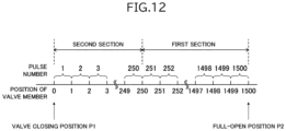
- Fig. 12 is a diagram illustrating a relationship between each pulse number and the position of the valve member, each of the pulse numbers being shown in the table in Fig. 11 and being assigned from the valve closing position to the full-open position.
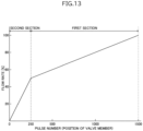
- Fig. 13 is a graph illustrating a relationship between the position of the valve member and the flow rate when the stepping motor of the electric valve illustrated in Fig. 1 rotates on the basis of the table illustrated in Fig. 11 .
- Fig. 14 is a diagram illustrating another modification of the table illustrated in Fig. 8 .
- Fig. 15 is a diagram illustrating a relationship between each pulse number and the position of the valve member, each of the pulse numbers being shown in the table in Fig. 14 and being assigned from the valve closing position to the full-open position.
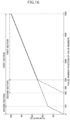
- Fig. 16 is a graph illustrating a relationship between the position of the valve member and the flow rate (flow-rate characteristics) when the stepping motor of the electric valve illustrated in Fig. 1 rotates on the basis of the table illustrated in Fig. 14 .
- the flow-rate characteristics in the start-up state is indicated by a one-dot chain line
- the flow-rate characteristics in the normal operating state is indicated by a solid line.
- the one-dot chain line and the solid line are vertically shifted from each other in the range from the position "650" to the position "1900", they actually match each other.
- the above-described electric valve 1 rotates the stepping motor 66 on the basis of the table 310, which is stored in the storage unit 210 of the control device 200 and illustrated in Fig. 8 .
- the electric valve 1A is the electric valve 1 that has a table 320 illustrated in Fig. 11 instead of the table 310 and has flow-rate characteristics different from those of the electric valve 1.
- the hardware configuration of the electric valve 1A is the same as that of the electric valve 1.
- the storage unit 210 stores the table 320 illustrated in Fig. 11 .
- the table 320 includes a section information area 321, a pulse-number information area 322, and a step-angle information area 323.
- section information area 321 items of information relating to the sections set between the valve closing position P1 and the full-open position P2 of the valve member 40 are set.
- the "second section” and the "first section” are set as the items of information relating to the sections.
- pulse-number information area 322 items of information (pulse number information) relating to the pulse numbers assigned in ascending order from the valve closing position P1 to the full-open position P2 of the valve member 40 are set.
- the pulse numbers "1" to “1500” are set as the items of the pulse number information.
- the pulse numbers "1" to "250” are assigned to the "second section” of the section information area 321, and the pulse numbers "251" to "1500” are assigned to the "first section” of the section information area 321.
- Fig. 12 illustrates the relationship between the position of the valve member 40 and each pulse number.
- the positions "0" to “1500” of the valve member 40 are set in ascending order from the valve closing position P1 to the full-open position P2.
- the pulse numbers "1" to “1500” are assigned to the intervals between the positions "0" to "1500".
- step-angle information area 323 items of information (step angle information) relating to step angles each of which corresponds to one of the pulse numbers set in the pulse-number information area 322 are set.
- step-angle information area 323 the numbers of divisions of the step angle used in the full-step operation are set as the items of the step angle information.
- "1" is set so as to correspond to the pulse numbers "1" to "250”
- "5" is set so as to correspond to the pulse numbers "251" to "1500”.
- 7.5 degrees/1 7.5 degrees
- the stepping motor 66 has different step angles in the second section and the first section.
- the electric valve 1A operates as an electric valve having the flow-rate characteristics illustrated in Fig. 13 .
- valve opening degrees 0[%] to 100[%] that are designated by the control unit 400 correspond to the positions "0" to "1500" of the valve member 40.
- the pulse rate when the valve member 40 is in the first section is set to be five times the pulse rate when the valve member 40 is in the second section.
- the pulse rate is 625 [PPS].
- the pulse rate is 125 [PPS].
- the control device 200 of the electric valve 1A is brought into the start-up state as a result of power being supplied thereto.
- the control device 200 performs initialization processing.
- the control device 200 causes the valve member 40 to move to the valve closing position P1 and then transitions to the normal operating state.
- the present position Pc of the valve member 40 is the valve closing position P1 (the position "0" of the valve member 40).
- the control device 200 waits for a command from the control unit 400.
- the control unit 400 determines that the electric valve 1A has the flow-rate characteristics illustrated in Fig. 13 .
- control device 200 when the control device 200 receives the valve-member movement command including the moving target position Pt that designates a valve opening degree of 90 [%] from the control unit 400, the control device 200 acquires the position "1350" as the moving target position Pt. Then, the control device 200 acquires the pulse numbers "1" to "1350” assigned from the present position Pc to the moving target position Pt.
- the control device 200 calculates the step angles corresponding to the pulse numbers "1" to "1350” on the basis of the table 320. Since the number indicating the present position Pc (the position "0") is smaller than the number indicating the moving target position Pt (the position "1350"), the control device 200 sets the rotation direction to the "valve opening direction”. The control device 200 inputs the pulses, the step angles, and the rotation direction to the motor driver so as to rotate the stepping motor 66. As a result, the valve member 40 moves away from the valve seat 18.
- the control device 200 inputs pulses at a rate of 125 [PPS] in the second section (the pulse numbers “1” to “250”) and inputs pulses at a rate of 625 [PPS] in the first section (the pulse numbers "251" to “1350”). In addition, the control device 200 adds up the step angles corresponding to the pulse numbers "1" to "1350".
- the control device 200 When rotation of the stepping motor 66 at the step angles corresponding to the pulse numbers "1" to "1350” is complete, the control device 200 stores the position "1350" into the working memory as the present position Pc. In addition, the control device 200 determines the success or failure of the valve-member movement command and transmits the command execution result of the valve-member movement command to the control unit 400. Then, the control device 200 waits for the next command from the control unit 400.
- control device 200 when the control device 200 receives the valve-member movement command including the moving target position Pt that designates a valve opening degree of 10[%] from the control unit 400, the control device 200 acquires the position "150" as the moving target position Pt. Then, the control device 200 acquires the pulse numbers "1350" to "151” assigned from the present position Pc to the moving target position Pt.
- the control device 200 calculates the step angles corresponding to the pulse numbers "1350" to "151” on the basis of the table 320. Since the number indicating the present position Pc (the position "1350") is larger than the number indicating the moving target position Pt (the position "150"), the control device 200 sets the rotation direction to the "valve closing direction”. The control device 200 inputs the pulses, the step angles, and the rotation direction to the motor driver so as to rotate the stepping motor 66 (the magnet rotor 31). As a result, the valve member 40 comes closer to the valve seat 18.
- the control device 200 inputs pulses at a rate of 625 [PPS] in the first section (the pulse numbers “1350” to “251") and inputs pulses at a rate of 125 [PPS] in the second section (the pulse numbers "250" to “151”). In addition, the control device 200 adds up the step angles corresponding to the pulse numbers "1350” to "151".
- the control device 200 When rotation of the stepping motor 66 at the step angles corresponding to the pulse numbers "1350" to "151” is complete, the control device 200 stores the position "150" into the working memory as the present position Pc. In addition, the control device 200 determines the success or failure of the valve-member movement command and transmits the command execution result of the valve-member movement command to the control unit 400. Then, the control device 200 waits for the next command from the control unit 400. Subsequently, the control device 200 performs operations in accordance with commands received thereby.
- the electric valve 1A achieves the same advantageous effects (including substantially the same advantageous effects) as the above-described electric valve 1.
- the first section and the second section are set between the valve closing position P1 and the full-open position P2 of the valve member 40.
- the first angle (1.5 degrees) is set as the step angle corresponding to the pulse number assigned to the first section.
- the second angle (7.5 degrees) is set as the step angle corresponding to the pulse number assigned to the second section.
- the first angle and the second angle are different from each other. Consequently, the electric valve 1A can obtain flow-rate characteristics having two sections with a different amount of change in the flow rate per pulse from one another.
- the electric valve 1A can precisely control the flow rate within a range where the valve opening degree is relatively large.
- the second angle is the step angle in the full-step operation of the stepping motor 66. Consequently, the electric valve 1A can obtain, with a relatively simple configuration, the flow-rate characteristics having two sections with a different amount of change in the flow rate per pulse from one another.
- n may be a natural number of two or more.
- the valve member 40 has the tapered surface 41 such that its diameter decreases toward the valve port 17.
- the flow rate is determined by the gap between the tapered surface 41 and the inner circumferential surface of the valve port 17. Consequently, the electric valve 1A can obtain, by using the valve member 40 having a relatively simple shape, the flow-rate characteristics having two sections with a different amount of change in the flow rate per pulse from one another.
- the pulse rate when the valve member 40 is in the first section is five times the pulse rate when the valve member 40 is in the second section. Consequently, in the electric valve 1A, the moving speed of the valve member 40 can be the same in the first section and the second section. As a result, the valve member 40 can be moved from the valve closing position P1 to the full-open position P2 more quickly than in the case where the pulse rate is the same in the first section and the second section.
- the electric valve 1B is the electric valve 1 that has tables 330 and 340 illustrated in Fig. 14 instead of the table 310 illustrated in Fig. 8 and has flow-rate characteristics different from those of the electric valve 1.
- the hardware configuration of the electric valve 1B is the same as that of the electric valve 1.
- the storage unit 210 stores the tables 330 and 340 illustrated in Fig. 14 .
- the table 330 is used in the start-up state immediately after power is supplied to the electric valve 1B.
- the table 340 is used in the normal operating state after transitioning from the start-up state of the electric valve 1B.
- the table 330 includes a section information area 331, a pulse-number information area 332, and a step-angle information area 333.
- section information area 33 items of information relating to the sections set between the valve closing position P1 and the full-open position P2 of the valve member 40 are set.
- the "second section” and the "first section” are set as the items of information relating to the sections.
- pulse-number information area 332 items of information (pulse number information) relating to the pulse numbers assigned in ascending order from the valve closing position P1 to the full-open position P2 of the valve member 40 are set.
- pulse numbers "401" to "1900” are set as the items of the pulse number information.
- the pulse numbers "401" to "650” are assigned to the "second section” of the section information area 331, and the pulse numbers "651" to "1900" are assigned to the "first section” of the section information area 331.
- step-angle information area 333 items of information (step angle information) relating to step angles each of which corresponds to one of the pulse numbers set in the pulse-number information area 332 are set.
- step-angle information area 333 the numbers of divisions of the step angle used in the full-step operation are set as the items of the step angle information.
- "1" is set so as to correspond to the pulse numbers "401" to "650”
- "5" is set so as to correspond to the pulse numbers "651" to "1900”.
- the table 340 includes a section information area 341, a pulse-number information area 342, and a step-angle information area 343.
- section information area 34 items of information relating to the sections set between the valve closing position P1 and the full-open position P2 of the valve member 40 are set.
- the "second section” and the "first section” are set as the items of information relating to the sections.
- pulse-number information area 342 items of information (pulse number information) relating to the pulse numbers assigned in ascending order from the valve closing position P1 to the full-open position P2 of the valve member 40 are set.
- the pulse numbers "1" to "1900” are set as the items of the pulse number information.
- the pulse numbers "1" to "150” are assigned to the "second section” of the section information area 341, and the pulse numbers "151" to "1900" are assigned to the "first section” of the section information area 341.
- step-angle information area 343 items of information (step angle information) relating to step angles each of which corresponds to one of the pulse numbers set in the pulse-number information area 342 are set.
- step-angle information area 343 the numbers of divisions of the step angle used in the full-step operation are set as the items of the step angle information.
- "1" is set so as to correspond to the pulse numbers "1" to "150”
- "5" is set so as to correspond to the pulse numbers "151” to "1900”.
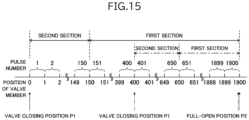
- Fig. 15 illustrates the relationship between the position of the valve member 40 and each pulse number.
- the valve closing position P1, the full-open position P2, the first section, and the second section in the start-up state are each indicated by a one-dot chain line
- the valve closing position P1, the full-open position P2, the first section, and the second section in the normal operating state are each indicated by a solid line.
- the positions "400" to "1900" of the valve member 40 are set in ascending order from the valve closing position P1 to the full-open position P2 so as to correspond to the table 330, which is used in the start-up state.
- the pulse numbers "401" to "1900” are assigned to the intervals between the positions "400" to "1900".
- the positions "0" to “1900" of the valve member 40 are set in ascending order from the valve closing position P1 to the full-open position P2 so as to correspond to the table 340, which is used in the normal operating state.
- the pulse numbers "1" to “1900” are assigned to the intervals between the positions "0" to "1900".
- the pulse number information set in the pulse-number information area 332 is start-up-state pulse-number information
- the step angle information set in the step-angle information area 333 is start-up-state step-angle information
- the pulse number information set in the pulse-number information area 342 is normal-operating-state pulse-number information
- the step angle information set in the step-angle information area 343 is normal-operating-state step-angle information.
- the pulse numbers "401" to "1900" are set as the items of the start-up-state pulse-number information
- the pulse numbers "1" to "1900” are set as the items of the normal-operating-state pulse-number information.
- start-up-state pulse-number information and the normal-operating-state pulse-number information are different from each other.
- "1" is assigned to the pulse numbers "401" to "650" of the start-up-state pulse-number information as the start-up-state step-angle information
- "5" is assigned to the pulse numbers "651" to "1900" of the start-up-state pulse-number information as the start-up-state step-angle information.
- the computing unit 230 transitions from the start-up state to the normal operating state.
- the valve opening degrees 0[%] to 100[%] that are designated by the control unit 400 correspond to the positions "400" to "1900" of the valve member 40.
- the valve opening degrees 0[%] to 100[%] that are designated by the control unit 400 correspond to the positions "0" to "1900" of the valve member 40.
- the computing unit 230 acquires the position of the valve member 40 that corresponds to the valve opening degree designated by the moving target position Pt of the valve-member movement command.
- the computing unit 230 acquires the position "550" as the moving target position Pt.
- the computing unit 230 acquires the position "1150” as the moving target position Pt.
- the computing unit 230 acquires the position "1600” as the moving target position Pt.
- the computing unit 230 acquires the position "190" as the moving target position Pt.
- the computing unit 230 acquires the position "950” as the moving target position Pt.
- the computing unit 230 acquires the position "1520" as the moving target position Pt.
- the control device 200 of the electric valve 1B causes the stepping motor 66 to rotate by using the table 330 in the start-up state and causes the stepping motor 66 to rotate by using the table 340 in the normal operating state.
- the control device 200 of the electric valve 1B is brought into the start-up state as a result of power being supplied thereto.
- the control device 200 performs initialization processing.
- the control device 200 causes the valve member 40 to move to the valve closing position P1.
- the present position Pc of the valve member 40 is the valve closing position P1 (the position "400" of the valve member 40).
- the control device 200 waits for a command from the control unit 400.
- the control unit 400 determines that the electric valve 1B in the start-up state has the flow-rate characteristics indicated by the one-dot chain line in Fig. 16 and that the electric valve 1B in the normal operating state has the flow-rate characteristics indicated by the solid line in Fig. 16 .
- control device 200 when the control device 200 receives the valve-member movement command including the moving target position Pt that designates a valve opening degree of 80[%] from the control unit 400, the control device 200 acquires the position "1600” as the moving target position Pt. Then, the control device 200 acquires the pulse numbers "401" to "1600” assigned from the present position Pc to the moving target position Pt.
- the control device 200 calculates the step angles corresponding to the pulse numbers "401" to "1600” on the basis of the table 330. Since the number indicating the present position Pc (the position "400") is smaller than the number indicating the moving target position Pt (the position "1600"), the control device 200 sets the rotation direction to the "valve opening direction”. The control device 200 inputs the pulses, the step angles, and the rotation direction to the motor driver so as to rotate the stepping motor 66. As a result, the valve member 40 moves away from the valve seat 18.
- the control device 200 inputs pulses at a rate of 125 [PPS] in the second section (the pulse numbers "401" to “650") and inputs pulses at a rate of 625 [PPS] in the first section (the pulse numbers "651" to “1600”). In addition, the control device 200 adds up the step angles corresponding to the pulse numbers "401" to "1600".
- the control device 200 When rotation of the stepping motor 66 at the step angles corresponding to the pulse numbers "401" to “1600” is complete, the control device 200 stores the position "1600” into the working memory as the present position Pc. In addition, the control device 200 determines the success or failure of the valve-member movement command and transmits the command execution result of the valve-member movement command to the control unit 400. Then, the control device 200 waits for the next command from the control unit 400.
- control device 200 transitions from the start-up state to the normal operating state.
- the control device 200 uses the table 340 instead of the table 330.
- the control device 200 when the control device 200 receives the valve-member movement command including the moving target position Pt that designates a valve opening degree of 50[%] from the control unit 400, the control device 200 acquires the position "950" as the moving target position Pt. Then, the control device 200 acquires the pulse numbers "1600” to "951" assigned from the present position Pc to the moving target position Pt.
- the control device 200 calculates the step angles corresponding to the pulse numbers "1600” to "951" on the basis of the table 340. Since the number indicating the present position Pc (the position "1600”) is larger than the number indicating the moving target position Pt (the position "950"), the control device 200 sets the rotation direction to the "valve closing direction". The control device 200 inputs the pulses, the step angles, and the rotation direction to the motor driver so as to rotate the stepping motor 66. As a result, the valve member 40 comes closer to the valve seat 18.
- the control device 200 inputs pulses at a rate of 625 [PPS] in the first section (the pulse numbers “1600” to “951"). In addition, the control device 200 adds up the step angles corresponding to the pulse numbers "1600” to "951".
- the control device 200 When rotation of the stepping motor 66 at the step angles corresponding to the pulse numbers "1600” to “951” is complete, the control device 200 stores the position "951" into the working memory as the present position Pc. In addition, the control device 200 determines the success or failure of the valve-member movement command and transmits the command execution result of the valve-member movement command to the control unit 400. Then, the control device 200 waits for the next command from the control unit 400.
- the control device 200 when the control device 200 receives the valve-member movement command including the moving target position Pt that designates a valve opening degree of 0[%] from the control unit 400, the control device 200 acquires the position "0" as the moving target position Pt. Then, the control device 200 acquires the pulse numbers "950" to "1" assigned from the present position Pc to the moving target position Pt.
- the control device 200 calculates the step angles corresponding to the pulse numbers "950" to "1" on the basis of the table 340. Since the number indicating the present position Pc (the position "950") is larger than the number indicating the moving target position Pt (the position "0"), the control device 200 sets the rotation direction to the "valve closing direction". The control device 200 inputs the pulses, the step angles, and the rotation direction to the motor driver so as to rotate the stepping motor 66. As a result, the valve member 40 comes into contact with the valve seat 18.
- the control device 200 inputs pulses at a rate of 625 [PPS] in the first section (the pulse numbers “950” to “151”) and inputs pulses at a rate of 125 [PPS] in the second section (the pulse numbers "150" to “1"). In addition, the control device 200 adds up the step angles corresponding to the pulse numbers "950" to "1".
- the control device 200 When rotation of the stepping motor 66 at the step angles corresponding to the pulse numbers "950" to “1" is complete, the control device 200 stores the position "0" into the working memory as the present position Pc. In addition, the control device 200 determines the success or failure of the valve-member movement command and transmits the command execution result of the valve-member movement command to the control unit 400. Then, the control device 200 waits for the next command from the control unit 400. Subsequently, the control device 200 performs operations in accordance with commands received thereby.
- the electric valve 1B achieves the same advantageous effects (including substantially the same advantageous effects) as the electric valve 1 and the electric valve 1A that have been described above.
- the storage unit 210 stores the table 330 and the table 340.
- the control device uses the pulse number information and the step angle information (the start-up-state pulse-number information and the start-up-state step-angle information) set in the table 330.
- the control device uses the pulse number information and the step angle information (the normal-operating-state pulse-number information and the normal-operating-state step-angle information) set in the table 340. Consequently, the electric valve 1B can change the flow-rate characteristics during its operation and can respond more flexibly to requirements of the system in which the electric valve 1B is incorporated.
- control device 200 in the start-up state receives the normal-operation start command from the control unit 400, the control device 200 transitions to the normal operating state. Consequently, the operating state of the control device 200 can be changed by the control unit 400. Thus, compared with the case where the control device 200 autonomously changes its operating state, a discrepancy can be prevented from occurring between the operating state of the control device 200 as determined by the control unit 400 and the actual operating state of the control device 200.
- valve member 40 moves to a predetermined start-up completion position (for example, position "650" in Fig. 16 ) when the control device 200 is in the start-up state, the control device 200 may autonomously transition to the normal operating state.
- a predetermined start-up completion position for example, position "650" in Fig. 16
- the electric valve 1 is a direct-driving electric valve that includes the driving mechanism 30 using the rotation of the magnet rotor 31 without speed being reduced
- the present invention is also applicable to an electric valve that includes a driving mechanism having a mechanism for reducing rotation speed of a magnet rotor.
- a “member that has a circular cylindrical shape” includes a member that has a circular cylindrical shape and a member that has a substantially circular cylindrical shape.
- ... stator unit 60 ... stator, 60a ... stator inner circumferential surface, 61 ... A-phase stator, 61a ... pole tooth, 61b ... pole tooth, 61c ... coil, 62 ... B-phase stator, 62a ... pole tooth, 62b ... pole tooth, 62c ... coil, 63 ... molded member, 64 ... terminal supporting portion, 65 ... terminal, 66 ... stepping motor, 70 ... housing, 71 ... peripheral wall portion, 71a ...
Landscapes
- Engineering & Computer Science (AREA)
- General Engineering & Computer Science (AREA)
- Mechanical Engineering (AREA)
- Power Engineering (AREA)
- Electrically Driven Valve-Operating Means (AREA)
Abstract
Description
- The present invention relates to an electric valve that is used in, for example, a refrigeration cycle system of an air-conditioning apparatus.
-
Patent Literature 1 discloses an electric valve of the related art. The electric valve described inPatent Literature 1 includes a valve member and a stepping motor. The valve member faces a valve port. The valve member is moved, as a result of rotation of the stepping motor, in a direction in which the valve member faces the valve port. - Patent Literature 1:
Japanese Unexamined Patent Application Publication No. 8-268030 - In the electric valve described above, the stepping motor rotates in response to pulses. The rotation angle (the step angle) per pulse of the stepping motor is constant, and the amount of movement of the valve member per pulse is also constant. Thus, the flow-rate characteristics of the electric valve depend on the shape of the valve member. In order to obtain desired flow-rate characteristics, it is necessary to use a valve member that has a shape corresponding to the flow-rate characteristics.
- Accordingly, an object of the present invention is to provide an electric valve capable of obtaining desired flow-rate characteristics without depending on the shape of a valve member.
- To obtain the above-described object, an electric valve according to the present invention includes a valve body that has a valve port, a valve member that faces the valve port, a driving mechanism that moves the valve member in a direction in which the valve member faces the valve port, and a control device that controls the driving mechanism. The driving mechanism includes a stepping motor, and rotation of the stepping motor causes the valve member to move. The control device includes a storage unit configured to store pulse number information and step angle information, the pulse number information relating to pulse numbers that are sequentially assigned from a reference position of the valve member to a full-open position of the valve member, and the step angle information relating to step angles each of which corresponds to one of the pulse numbers, a communication unit configured to receive a valve-member movement command from an external device, the valve-member movement command relating to a moving target position of the valve member, a computing unit configured to acquire the pulse numbers assigned from a present position of the valve member to the moving target position of the valve member, and a rotation control unit configured to rotate the stepping motor at the step angles corresponding to the pulse numbers, which are assigned from the present position of the valve member to the moving target position of the valve member, in an order of the pulse numbers.
- In the present invention, it is preferable that a first section, a second section, and a third section be set between the reference position of the valve member and the full-open position of the valve member. It is preferable that a first angle be set as the step angle corresponding to the pulse numbers assigned to the first section. It is preferable that a second angle be set as the step angle corresponding to the pulse numbers assigned to the second section. It is preferable that a third angle be set as the step angle corresponding to the pulse numbers assigned to the third section. It is preferable that the first angle, the second angle, and the third angle be different from one another.
- In the present invention, it is preferable that the first angle be a step angle in a micro-step operation that is 1/n of a step angle in a full-step operation of the stepping motor. It is preferable that the second angle be a step angle in a micro-step operation that is 1/m of the step angle in the full-step operation of the stepping motor. It is preferable that the third angle be the step angle in the full-step operation of the stepping motor. Note that m and n are each a natural number of two or more, with a condition that m ≠ n.
- In the present invention, it is preferable that the valve member have a tapered surface such that a diameter of the valve member decreases toward the valve port. It is preferable that, when the valve member is in the first section, the second section, or the third section, a flow rate be determined by a gap between the tapered surface and an inner circumferential surface of the valve port.
- In the present invention, it is preferable that a pulse rate when the valve member is in the first section be n times a pulse rate when the valve member is in the third section. It is preferable that a pulse rate when the valve member is in the second section be m times the pulse rate when the valve member is in the third section.
- In the present invention, it is preferable that a first section and a second section be set between the reference position of the valve member and the full-open position of the valve member. It is preferable that a first angle be set as the step angle corresponding to the pulse numbers assigned to the first section. It is preferable that a second angle be set as the step angle corresponding to the pulse numbers assigned to the second section. It is preferable that the first angle and the second angle be different from each other.
- In the present invention, it is preferable that the first angle be a step angle in a micro-step operation that is 1/n of a step angle in a full-step operation of the stepping motor. It is preferable that the second angle be the step angle in the full-step operation of the stepping motor. Note that n is a natural number of two or more.
- In the present invention, it is preferable that the valve member have a tapered surface such that a diameter of the valve member decreases toward the valve port. It is preferable that, when the valve member is in the first section or the second section, a flow rate be determined by a gap between the tapered surface and an inner circumferential surface of the valve port.
- In the present invention, it is preferable that a pulse rate when the valve member is in the first section be n times a pulse rate when the valve member is in the second section.
- In the present invention, it is preferable that the storage unit store start-up-state pulse-number information and start-up-state step-angle information, the start-up-state pulse-number information relating to pulse numbers that are sequentially assigned from the reference position of the valve member to the full-open position of the valve member, and the start-up-state step-angle information relating to step angles each of which corresponds to one of the pulse numbers of the start-up-state pulse-number information. It is preferable that the storage unit store normal-operating-state pulse-number information and normal-operating-state step-angle information, the normal-operating-state pulse-number information relating to pulse numbers that are sequentially assigned from the reference position of the valve member to the full-open position of the valve member, and the normal-operating-state step-angle information relating to step angles each of which corresponds to one of the pulse numbers of the normal-operating-state pulse-number information. It is preferable that the control device use, in a start-up state, the start-up-state pulse-number information and the start-up-state step-angle information as the pulse number information and the step angle information and use, in a normal operating state after transitioning from the start-up state, the normal-operating-state pulse-number information and the normal-operating-state step-angle information as the pulse number information and the step angle information.
- In the present invention, it is preferable that, when the communication unit receives a normal-operation start command from an external device in the start-up state, the control device make a transition to the normal operating state.
- In the present invention, it is preferable that, when the valve member moves to a predetermined start-up completion position in the start-up state, the control device make a transition to the normal operating state.
- According to the present invention, the control device of the electric valve stores the pulse number information relating to the pulse numbers that are sequentially assigned from the reference position of the valve member to the full-open position of the valve member and the step angle information relating to the step angles each of which corresponds to one of the pulse numbers. The control device receives the valve-member movement command relating to the moving target position of the valve member from the external device. The control device acquires the pulse numbers assigned from the present position of the valve member to the moving target position. The control device rotates the stepping motor at the step angles corresponding to the pulse numbers assigned from the present position of the valve member to the moving target position in the order of these pulse numbers. With this configuration, the electric valve can individually set a step angle for each pulse assigned from the reference position of the valve member to the full-open position and can adjust the amount of movement of the valve member per pulse (i.e., the amount of change in the flow rate of a refrigerant flowing through a valve port). Therefore, in the electric valve, desired flow-rate characteristics can be obtained without depending on the shape of a valve member.
-
- [
Fig. 1] Fig. 1 is a sectional view of an electric valve according to an embodiment of the present invention. - [
Fig. 2] Fig. 2 is a sectional view of a stator unit of the electric valve illustrated inFig. 1 . - [
Fig. 3] Fig. 3 is an enlarged sectional view of a valve member and members in its vicinity that are included in the electric valve illustrated inFig. 1 when the valve member of the electric valve is located at a valve closing position. - [
Fig. 4] Fig. 4 is an enlarged sectional view of the valve member and the members in its vicinity that are included in the electric valve illustrated inFig. 1 when the valve member is located at a full-open position. - [
Fig. 5] Fig. 5 is a graph illustrating a relationship between valve opening degree and flow rate in the electric valve illustrated inFig. 1 . - [
Fig. 6] Fig. 6 is a diagram illustrating a positional relationship between a magnet rotor and a stator that are included in the electric valve illustrated inFig. 1 . - [
Fig. 7] Fig. 7 is a functional block diagram of the electric valve illustrated inFig. 1 . - [
Fig. 8] Fig. 8 is a diagram illustrating a table relating to pulse number information and step angle information that are stored in a control device of the electric valve illustrated inFig. 1 . - [
Fig. 9] Fig. 9 is a diagram illustrating a relationship between each pulse number and a position of the valve member, each of the pulse numbers being shown in the table inFig. 8 and being assigned from the valve closing position to the full-open position. - [
Fig. 10] Fig. 10 is a graph illustrating a relationship between the position of the valve member and the flow rate when a stepping motor of the electric valve illustrated inFig. 1 rotates on the basis of the table illustrated inFig. 8 . - [
Fig. 11] Fig. 11 is a diagram illustrating a modification of the table illustrated inFig. 8 . - [
Fig. 12] Fig. 12 is a diagram illustrating a relationship between each pulse number and the position of the valve member, each of the pulse numbers being shown in the table inFig. 11 and being assigned from the valve closing position to the full-open position. - [
Fig. 13] Fig. 13 is a graph illustrating a relationship between the position of the valve member and the flow rate when the stepping motor of the electric valve illustrated inFig. 1 rotates on the basis of the table illustrated inFig. 11 . - [
Fig. 14] Fig. 14 is a diagram illustrating another modification of the table illustrated inFig. 8 . - [
Fig. 15] Fig. 15 is a diagram illustrating a relationship between each pulse number and the position of the valve member, each of the pulse numbers being shown in the table inFig. 14 and being assigned from the valve closing position to the full-open position. - [
Fig. 16] Fig. 16 is a graph illustrating a relationship between the position of the valve member and the flow rate when the stepping motor of the electric valve illustrated inFig. 1 rotates on the basis of the table illustrated inFig. 14 . - An
electric valve 1 according to an embodiment of the present invention will be described below with reference toFig. 1 to Fig. 10 . For example, theelectric valve 1 is incorporated in a refrigeration cycle system of an air-conditioning apparatus and operates in accordance with a command from acontrol unit 400 of the air-conditioning apparatus. Thecontrol unit 400 is an external device that is provided outside theelectric valve 1. -
Fig. 1 is a sectional view of the electric valve according to the embodiment of the present invention.Fig. 2 is a sectional view of a stator unit of the electric valve illustrated inFig. 1 .Fig. 3 andFig. 4 are each an enlarged sectional view of a valve member and members in its vicinity that are included in the electric valve illustrated inFig. 1 .Fig. 3 illustrates a state where the valve member is located at a valve closing position.Fig. 4 illustrates a state where the valve member is located at a full-open position.Fig. 5 is a graph illustrating a relationship between valve opening degree and flow rate in the electric valve illustrated inFig. 1 .Fig. 6 is a diagram illustrating a positional relationship between a magnet rotor and a stator that are included in the electric valve illustrated inFig. 1 .Fig. 6A illustrates a state where magnetic poles of the magnet rotor and pole teeth of an A-phase stator face each other.Fig. 6B illustrates a state where the magnetic poles of the magnet rotor and pole teeth of a B-phase stator face each other.Fig. 7 is a functional block diagram of the electric valve illustrated inFig. 1 .Fig. 8 is a diagram illustrating a table relating to pulse number information and step angle information that are stored in a control device of the electric valve illustrated inFig. 1 .Fig. 9 is a diagram illustrating a relationship between each pulse number and a position of the valve member, each of the pulse numbers being shown in the table inFig. 8 and being assigned from the valve closing position to the full-open position.Fig. 10 is a graph illustrating a relationship between the position of the valve member and the flow rate when a stepping motor of the electric valve illustrated inFig. 1 rotates on the basis of the table illustrated inFig. 8 . - As illustrated in
Fig. 1 andFig. 2 , theelectric valve 1 includes avalve body 10, acan 20, adriving mechanism 30, and avalve member 40. - The
valve body 10 is made of a metal such as an aluminum alloy. Thevalve body 10 includes abody member 11, a supportingmember 12, and a connectingmember 13. Thebody member 11 has a rectangular parallelepiped shape. Thebody member 11 includes avalve chamber 14 andflow channels flow channel 15 is connected to thevalve chamber 14. Theflow channel 16 is connected to thevalve chamber 14 via avalve port 17. In thevalve chamber 14, thevalve port 17 is enclosed by avalve seat 18 that has a circular annular shape. A mountinghole 11a is formed in an upper surface of thebody member 11 so as to communicate with thevalve chamber 14. The supportingmember 12 has a circular cylindrical shape. The supportingmember 12 is attached to the mountinghole 11a of thebody member 11 by using a screw structure. An upper portion of the supportingmember 12 projects from the upper surface of thebody member 11. The connectingmember 13 has a circular annular plate-like shape. The inner circumferential edge of the connectingmember 13 is joined to an upper end of the supportingmember 12. - The
can 20 is made of a metal such as a stainless steel. Thecan 20 has a circular cylindrical shape whose lower end is open and whose upper end is closed. The lower end of thecan 20 is joined to an outer circumferential edge of the connectingmember 13. - The
driving mechanism 30 causes thevalve member 40 to move in the vertical direction (a direction in which an axis L extends). Thedriving mechanism 30 includes amagnet rotor 31, avalve stem holder 32, a guide bush 33, avalve stem 34, apermanent magnet 38, and astator unit 50. - The
magnet rotor 31 has a circular cylindrical shape. The outer diameter of themagnet rotor 31 is slightly smaller than the inner diameter of thecan 20. Themagnet rotor 31 has a plurality of N-poles and a plurality of S-poles. The plurality of N-poles and the plurality of S-poles are arranged at the outer circumferential surface of themagnet rotor 31. The plurality of N-poles and the plurality of S-poles each extend in the vertical direction. The plurality of N-poles and the plurality of S-poles are alternately arranged at equal angular intervals in a circumferential direction. In the present embodiment, themagnet rotor 31 has 12 N-poles and 12 S-poles. The angle between each of the N-poles and the adjacent S-pole is 15 degrees. - The
valve stem holder 32 has a circular cylindrical shape whose lower end is open and whose upper end is closed. A supportingring 35 is fixed to an upper end of thevalve stem holder 32. The supportingring 35 connects themagnet rotor 31 and thevalve stem holder 32 to each other. Aninternal thread 32c is formed in the inner circumferential surface of thevalve stem holder 32. - The guide bush 33 includes a
base portion 33a and a valve-stem supporting portion 33b. Thebase portion 33a and the valve-stem supporting portion 33b each have a circular cylindrical shape. Thebase portion 33a is press-fitted into afitting hole 12a that is formed in the supportingmember 12. The outer diameter of the valve-stem supporting portion 33b is smaller than the outer diameter of thebase portion 33a. The inner diameter of the valve-stem supporting portion 33b is the same as the inner diameter of thebase portion 33a. The valve-stem supporting portion 33b is coaxially connected to an upper end of thebase portion 33a. Anexternal thread 33c is formed on the outer circumferential surface of the valve-stem supporting portion 33b. Theexternal thread 33c is screwed into theinternal thread 32c of thevalve stem holder 32. The guide bush 33 is connected to the supportingmember 12. - The valve stem 34 includes a large-
diameter portion 34a and a small-diameter portion 34b. The large-diameter portion 34a and the small-diameter portion 34b each has a circular columnar shape. The outer diameter of the large-diameter portion 34a is slightly smaller than the inner diameter of the guide bush 33. The outer diameter of the small-diameter portion 34b is smaller than the outer diameter of the large-diameter portion 34a. The small-diameter portion 34b is coaxially connected to an upper end of the large-diameter portion 34a. The small-diameter portion 34b extends through thevalve stem holder 32. Apush nut 36 for retaining is attached to the small-diameter portion 34b. The valve stem 34 is positioned inside the guide bush 33 and inside the supportingmember 12. The valve stem 34 is supported by the guide bush 33 so as to be slidable in the vertical direction. A lower end of thevalve stem 34 is positioned in thevalve chamber 14. The valve stem 34 includes astep portion 34c between the large-diameter portion 34a and the small-diameter portion 34b. Thestep portion 34c is a circular annular flat surface that faces upward. Avalve closing spring 37 is disposed between thevalve stem holder 32 and thestep portion 34c. Thevalve closing spring 37 is a compression-coil spring. Thevalve closing spring 37 presses thevalve stem 34 downward. - The
permanent magnet 38 is disposed above themagnet rotor 31 inside thecan 20. Thepermanent magnet 38 has a circular annular, flat plate-like shape. Thepermanent magnet 38 has a single N-pole and a single S-pole. When thepermanent magnet 38 is divided into two portions by its diameter, the N-pole is located at one of the portions, and the S-pole is located at the other portion. Thepermanent magnet 38 is fixed to the supportingring 35 with a fixingmember 39 interposed therebetween. Thepermanent magnet 38 is rotated together with themagnet rotor 31. - The
valve member 40 is integrally connected to a lower end of the large-diameter portion 34a of thevalve stem 34. Thevalve member 40 is disposed in thevalve chamber 14. Thevalve member 40 faces thevalve port 17 in the vertical direction. Thevalve member 40 has a taperedsurface 41 such that its diameter gradually decreases toward thevalve port 17. The taperedsurface 41 extends in the axis L direction from a position near the lower end of the large-diameter portion 34a of thevalve stem 34 to atip end 40a of thevalve member 40. The vertical direction is the same as the directions in which thevalve member 40 and thevalve port 17 face each other. Note that thevalve member 40 may have a plurality of tapered surfaces having different taper angles. - The
valve member 40 is moved in the vertical direction by thedriving mechanism 30. Thevalve port 17 is opened and closed by the movement of thevalve element 40. Thevalve member 40 is moved from a valve closing position P1 (Fig. 3 ) to a full-open position P2 (Fig. 4 ). The valve closing position P1 is a position of thevalve member 40 at which the taperedsurface 41 is in contact with thevalve seat 18. The valve closing position P1 is a reference position. The full-open position P2 is a position of thevalve member 40 at which the position of thetip end 40a of thevalve member 40 in the vertical direction is the same as the position of thevalve seat 18 in the vertical direction. In theelectric valve 1, the flow rate of refrigerant that flows through thevalve port 17 depends on the size of a circular annular gap formed between thetapered surface 41 and the inner circumferential surface of thevalve port 17. - The graph illustrated in
Fig. 5 shows the relationship between the valve opening degree and the flow rate in theelectric valve 1. The valve opening degree corresponds to the position of thevalve member 40 with respect to the valve seat 18 (the amount by which thevalve member 40 is lifted from the valve closed position P1). The valve opening degree is expressed as a percentage. When thevalve member 40 is at the valve closing position P1, the valve opening degree is 0%, and when thevalve member 40 is at the full-open position P2, the valve opening degree is 100%. The flow rate is the flow rate of the refrigerant that flows through the electric valve 1 (the valve port 17). The flow rate is expressed as a percentage. When thevalve member 40 is at the valve closing position P1, the flow rate is 0%, and when thevalve member 40 is at the full-open position P2, the flow rate is 100%. In the present embodiment, the flow rate is expressed as a percentage with respect to the Cv value. As illustrated inFig. 5 , a basic flow-rate characteristic of the electric valve 1 (the valve member 40) is a linear characteristic in which the flow rate linearly changes in proportion to the valve opening degree. Note that thevalve member 40 may have, for example, a shape with which its basic flow-rate characteristic is an equal-percentage characteristic. - The
stator unit 50 includes astator 60, ahousing 70, acase 80, amain circuit board 90, asub circuit board 100, amagnetic sensor 110, and amicrocomputer 120. - The
stator 60 has a circular cylindrical shape. Thestator 60 includes anA-phase stator 61, a B-phase stator 62, and a molded member 63 that is made of a synthetic resin. - The
A-phase stator 61 includes a plurality of claw-poletype pole teeth pole teeth 61a face downward, and the ends of thepole teeth 61b face upward. Thepole teeth 61a and thepole teeth 61b are alternately arranged at equal angular intervals in the circumferential direction. In the present embodiment, theA-phase stator 61 includes 12pole teeth pole teeth 61b. The angle between each of thepole teeth 61a and theadjacent pole tooth 61b is 15 degrees. When acoil 61c of theA-phase stator 61 is energized, thepole teeth 61a and thepole teeth 61b have mutually opposite polarities. - The B-
phase stator 62 includes a plurality of claw-poletype pole teeth pole teeth 62a face downward, and the ends of thepole teeth 62b face upward. Thepole teeth 62a and thepole teeth 62b are alternately arranged at equal angular intervals in the circumferential direction. In the present embodiment, the B-phase stator 62 includes 12pole teeth pole teeth 62b. The angle between each of thepole teeth 62a and theadjacent pole tooth 62b is 15 degrees. When acoil 62c of the B-phase stator 62 is energized, thepole teeth 62a and thepole teeth 62b have mutually opposite polarities. - The
A-phase stator 61 and the B-phase stator 62 are arranged so as to be coaxial with each other. TheA-phase stator 61 and the B-phase stator 62 are in contact with each other. When viewed in the direction in which an axis L extends, the angle between each of thepole teeth 61a of theA-phase stator 61 and theadjacent pole tooth 62a of the B-phase stator 62 is 7.5 degrees. - The
A-phase stator 61 and the B-phase stator 62 are filled with the molded member 63. In addition, the molded member 63 forms, together with thepole teeth pole teeth circumferential surface 60a. The diameter of the stator innercircumferential surface 60a is the same as the diameter of the outer circumferential surface of thecan 20. The molded member 63 includes aterminal supporting portion 64. - The
terminal supporting portion 64 extends in the lateral direction (a direction perpendicular to the axis L) from theA-phase stator 61 and the B-phase stator 62. Theterminal supporting portion 64 supports a plurality ofterminals 65. Each of the plurality ofterminals 65 projects in the lateral direction from an end of theterminal supporting portion 64. The plurality ofterminals 65 are connected to thecoil 61c of theA-phase stator 61 and thecoil 62c of the B-phase stator 62. - The
can 20 is disposed inside thestator 60. Themagnet rotor 31 is disposed inside thecan 20. Thestator 60 and themagnet rotor 31 constitute a steppingmotor 66. - The stepping
motor 66 is capable of performing a full-step operation and a micro-step operation. The full-step operation is an operation that causes themagnet rotor 31 to rotate, in response to a single pulse input, from a position (the position illustrated inFig. 6A ) where the magnetic poles (the N-poles and the S-poles) face thepole teeth A-phase stator 61 to a position (the position illustrated inFig. 6B ) where the magnetic poles face thepole teeth phase stator 62, which are adjacent to thepole teeth magnet rotor 31 to rotate, in response to a single pulse input, from the position illustrated inFig. 6B to the position illustrated inFig. 6A . InFig. 6A and Fig. 6B , a black dot is given to the magnetic pole that functions as a reference and to the pole tooth that functions as a reference. In the present embodiment, the rotation angle (a step angle) per pulse used in the full-step operation is 7.5 degrees. The micro-step operation is an operation that causes themagnet rotor 31 to rotate, in response to a single pulse input, at an angle obtained by equally dividing the step angle used in the full-step operation. The angle is a step angle used in the micro-step operation. The micro-step operation is performed by finely controlling the current value of thecoil 61c of theA-phase stator 61 and the current value of thecoil 62c of the B-phase stator 62. The step angle used in the micro-step operation is, for example, 0.9375 degrees (eight divisions), 1.875 degrees (four divisions), or 1.5 degrees (five divisions). - In the present embodiment, the stepping
motor 66, in a state where thevalve member 40 is at the valve closing position P1, performs the full-step operation of 500 pulses (rotation of themagnet rotor 31 by 3750 degrees), causing thevalve member 40 to move to the full-open position P2. - The
housing 70 is made of a synthetic resin. Thehousing 70 is formed by injection molding. Thehousing 70 accommodates thestator 60. Thehousing 70 includes aperipheral wall portion 71 and anupper wall portion 72. - The
peripheral wall portion 71 has a circular cylindrical shape. Thestator 60 is embedded in a center portion of theperipheral wall portion 71 in the vertical direction. The diameter of an innercircumferential surface 71a of theperipheral wall portion 71 is the same as the diameter of the stator innercircumferential surface 60a. The innercircumferential surface 71a is connected to the stator innercircumferential surface 60a with no difference in level. Theupper wall portion 72 has a dome-like shape. Theupper wall portion 72 is connected to an upper end of theperipheral wall portion 71. The innercircumferential surface 71a of theperipheral wall portion 71, theinner surface 72a of theupper wall portion 72, and the stator innercircumferential surface 60a define aninner space 74 of thestator unit 50. Thecan 20 is disposed in theinner space 74. The supportingmember 12 is disposed inside alower portion 73 of theperipheral wall portion 71. Aseal 19 having a circular annular shape is disposed between thelower portion 73 of theperipheral wall portion 71 and the supportingmember 12. Theseal 19 is made of an elastic material such as a rubber material. Theseal 19 suppresses entry of moisture into theinner space 74. - The
housing 70 includes a sub-circuit-board housing space 75. The sub-circuit-board housing space 75 extends in the lateral direction. The sub-circuit-board housing space 75 is adjacent to theinner space 74. Apartition wall 76 is disposed between theinner space 74 and the sub-circuit-board housing space 75. Thepartition wall 76 isolates theinner space 74 and the sub-circuit-board housing space 75 from each other. - The
case 80 is made of a synthetic resin. Thecase 80 is formed by injection molding. Thecase 80 includes acase body 81, alid body 82, and aconnector 83. Thecase body 81 has a rectangular parallelepiped box shape with one side surface (the right-hand side surface inFig. 1 andFig. 2 ) open. Thelid body 82 has a flat plate-like shape. Thelid body 82 closes an opening in the side surface of thecase body 81. Theconnector 83 has an oval cylindrical shape. Theconnector 83 extends in the lateral direction from an upper portion of thecase body 81. Thecase body 81 and theconnector 83 are integrally formed. - The
case body 81 includes aside wall portion 84. Theside wall portion 84 has a flat plate-like shape. Theside wall portion 84 faces thelid body 82 with a space formed therebetween in the lateral direction. Theside wall portion 84 has acase opening 84a that has a rectangular shape. Thecase opening 84a communicates with the sub-circuit-board housing space 75 of thehousing 70. A circumferential edge portion of the case opening 84a in theside wall portion 84 is joined to thehousing 70. - The
main circuit board 90 is a printed circuit board on which electronic components are mounted. Themain circuit board 90 is disposed along the vertical direction inside thecase 80. Acircuit board connector 91 is disposed on a surface of themain circuit board 90, the surface facing theside wall portion 84. Themicrocomputer 120 is mounted on themain circuit board 90. The plurality ofterminals 65 of thestator 60 are connected to themain circuit board 90. - The
sub circuit board 100 is a printed circuit board on which electronic components are mounted. Thesub circuit board 100 is disposed along the lateral direction in the sub-circuit-board housing space 75 of thehousing 70. Thesub circuit board 100 is disposed perpendicular to themain circuit board 90. Afirst end 100a of thesub circuit board 100 is disposed in the vicinity of themain circuit board 90. Asecond end 100b of thesub circuit board 100 is disposed in the vicinity of thepartition wall 76 of thehousing 70. - A
circuit board terminal 101 is disposed on thefirst end 100a of thesub circuit board 100. Thecircuit board terminal 101 is connected to thecircuit board connector 91 of themain circuit board 90. Thesub circuit board 100 is connected to themain circuit board 90 via thecircuit board terminal 101 and thecircuit board connector 91. - The
magnetic sensor 110 is a rotation angle sensor. Themagnetic sensor 110 is disposed on thesecond end 100b of thesub circuit board 100. Themagnetic sensor 110 faces thepermanent magnet 38 in the lateral direction with thecan 20 and thepartition wall 76 interposed therebetween. In other words, themagnetic sensor 110 and thepermanent magnet 38 are arranged side by side in the lateral direction with thecan 20 and thepartition wall 76 interposed therebetween. Themagnetic sensor 110 outputs a signal corresponding to the orientation of a magnetic field generated by the permanent magnet 38 (i.e., the rotation angle of themagnet rotor 31 that rotates together with the permanent magnet 38). - The
microcomputer 120 is, for example, a microcomputer for an embedded device. In the microcomputer, a central processing unit, a non-volatile memory, a working memory, a communication module, a motor driver, and so forth are integrated in one package. Themicrocomputer 120 functions as acontrol device 200 that is in charge of control of theelectric valve 1. The non-volatile memory, the working memory, the communication module, and the motor driver may be individual electronic components and may be externally connected to themicrocomputer 120. - As illustrated in
Fig. 7 , thecontrol device 200 includes astorage unit 210, acommunication unit 220, acomputing unit 230, and arotation control unit 240. The non-volatile memory constitutes thestorage unit 210. The central processing unit executes a program stored in the non-volatile memory and functions as thecommunication unit 220, thecomputing unit 230, and therotation control unit 240. The working memory temporarily stores variables including a present position Pc of thevalve member 40. The communication module is connected to thecontrol unit 400 of the air-conditioning apparatus via a cable (not illustrated) that is connected to theconnector 83. The motor driver is connected to the stepping motor 66 (thecoil 61c of theA-phase stator 61 and thecoil 62c of the B-phase stator 62). - The
storage unit 210 stores, for example, a table 310 illustrated inFig. 8 . The table 310 includes asection information area 311, a pulse-number information area 312, and a step-angle information area 313. - In the
section information area 311, items of information relating to sections set between the valve closing position P1 of thevalve member 40 and the full-open position P2 of thevalve member 40 are set. In thesection information area 311, a "first section", a "second section", and a "third section" are set as the items of information relating to the sections. - In the pulse-
number information area 312, items of information (pulse number information) relating to pulse numbers assigned in ascending order from the valve closing position P1 to the full-open position P2 of thevalve member 40 are set. In the pulse-number information area 312, pulse numbers "1" to "1500" are set as the items of the pulse number information. The pulse numbers "1" to "800" are assigned to the "first section" of thesection information area 311. The pulse numbers "801" to "1200" are assigned to the "second section" of thesection information area 311. The pulse numbers "1201" to "1500" are assigned to the "third section" of thesection information area 311. -
Fig. 9 illustrates the relationship between the position of thevalve member 40 and each of the pulse numbers. Positions "0" to "1500" of thevalve member 40 are set in ascending order from the valve closing position P1 to the full-open position P2. The pulse numbers "1" to "1500" are assigned to the intervals between the positions "0" to "1500". The pulse number "1" is assigned to the interval between the position "0" and the position "1", the pulse number "2" is assigned to the interval between the position "1" and the position "2", and so on. For example, when thevalve member 40 is at the position "1", the information relating to the pulse number "1" is used in order to move thevalve member 40 to the position "0", and the information relating to the pulse number "2" is used in order to move thevalve member 40 to the position "2". - In the step-
angle information area 313, items of information (step angle information) relating to step angles each of which corresponds to one of the pulse numbers set in the pulse-number information area 312 are set. In the step-angle information area 313, the numbers of divisions of the step angle used in the full-step operation are set as the items of the step angle information. In the step-angle information area 313, "8" is set so as to correspond to the pulse numbers "1" to "800", "4" is set so as to correspond to the pulse numbers "801" to "1200", and "1" is set so as to correspond to the pulse numbers "1201" to "1500". In other words, as a step angle (a first angle) of the "first section", 7.5 degrees/8 = 0.9375 degrees is set. As a step angle (a second angle) of the "second section", 7.5 degrees/4 = 1.875 degrees is set. As a step angle (a third angle) of the "third section", 7.5 degrees/1 = 7.5 degrees is set. The steppingmotor 66 has different step angles in the first section, the second section, and the third section. Note that, as the items of the step angle information, numerical values each indicating a step angle may be set. - Although the
storage unit 210 stores the pulse number information and the step angle information in a table format, thestorage unit 210 may store them in another format such as a mathematical expression. - As a result of the stepping motor 66 (the magnet rotor 31) being rotated on the basis of the table 310, the
electric valve 1 operates as an electric valve having the flow-rate characteristics illustrated inFig. 10 . - The
communication unit 220 communicates with thecontrol unit 400 through the communication module. Thecommunication unit 220 receives various commands from thecontrol unit 400 and transfers the commands to thecomputing unit 230. Thecommunication unit 220 acquires the state of theelectric valve 1 from thecomputing unit 230 and therotation control unit 240 and transmits it to thecontrol unit 400. Thecommunication unit 220 receives a valve-member movement command from thecontrol unit 400. The valve-member movement command includes information relating to a moving target position Pt of thevalve member 40, and the moving target position Pt is designated as the valve opening degree. Note that the moving target position Pt may be designated as a relative movement distance (the number of pulses or the like) from the present position Pc of thevalve member 40. The present position Pc of thevalve member 40 is stored in the working memory. - In the
electric valve 1, the valve opening degrees 0[%] to 100[%] that are designated by thecontrol unit 400 correspond to the positions "0" to "1500" of thevalve member 40. When the number that indicates the present position Pc of thevalve member 40 is smaller than the number that indicates the moving target position Pt, the direction of rotation of the steppingmotor 66 is a direction (a valve opening direction) in which thevalve member 40 moves away from thevalve seat 18. When the number that indicates the present position Pc of thevalve member 40 is larger than the number that indicates the moving target position Pt, the direction of rotation of the steppingmotor 66 is a direction (a valve closing direction) in which thevalve member 40 comes closer to thevalve seat 18. - The
computing unit 230 performs various computing operations. When thecommunication unit 220 receives the valve-member movement command, thecomputing unit 230 acquires the position of thevalve member 40 corresponding to the valve opening degree designated by the moving target position Pt of the valve-member movement command. For example, when the valve opening degree is 10[%], thecomputing unit 230 acquires the position "150" as the moving target position Pt. When the valve opening degree is 50[%], thecomputing unit 230 acquires the position "750" as the moving target position Pt. When the valve opening degree is 90[%], thecomputing unit 230 acquires the position "1350" as the moving target position Pt. - Then, the
computing unit 230 acquires the pulse number between the present position Pc (a starting point) of thevalve member 40 and the moving target position Pt (a destination point) of thevalve member 40. For example, when the present position Pc is the position "0" and the moving target position Pt is the position "150", thecomputing unit 230 acquires the pulse numbers "1" to "150". When the present position Pc is the position "150" and the moving target position Pt is the position "750", thecomputing unit 230 acquires the pulse numbers "151" to "750". When the present position Pc is the position "750" and the moving target position Pt is the position "300", thecomputing unit 230 acquires the pulse numbers "750" to "301". - In addition, the
computing unit 230 acquires the rotation angle of themagnet rotor 31 on the basis of the signal output by themagnetic sensor 110. - The
rotation control unit 240 acquires the items of the step angle information, each of which corresponds to one of the pulse numbers, one by one from the table 310 in the order of the pulse numbers assigned from the present position Pc of thevalve member 40 to the moving target position Pt. Then, therotation control unit 240 calculates the step angle by using the step angle information and inputs the pulses, the step angles, and the rotation direction to the motor driver so as to rotate the steppingmotor 66. - In the
rotation control unit 240, the pulse rate when thevalve member 40 is in the first section is set to be eight times the pulse rate when thevalve member 40 is in the third section. In therotation control unit 240, the pulse rate when thevalve member 40 is in the second section is set to be four times the pulse rate when thevalve member 40 is in the third section. The pulse rate is represented by the number of pulses input per second (PPS). In the present embodiment, when thevalve member 40 is in the first section, the pulse rate is 1000 [PPS]. When thevalve member 40 is in the second section, the pulse rate is 500 [PPS]. When thevalve member 40 is in the third section, the pulse rate is 125 [PPS]. - In addition, the
rotation control unit 240 determines the success or failure of the valve-member movement command. More specifically, therotation control unit 240 compares the rotation angle of themagnet rotor 31 that is obtained by adding up the step angles, each of which corresponds to one of the pulse numbers assigned from the present position Pc to the moving target position Pt, and the rotation angle of themagnet rotor 31 that is acquired by thecomputing unit 230 on the basis of the signal of themagnetic sensor 110. When these rotation angles match each other, therotation control unit 240 transmits, as a command execution result, information indicating that the valve-member movement command was successful to thecontrol unit 400 via thecommunication unit 220. When these rotation angles do not match each other, therotation control unit 240 transmits, as the command execution result, information indicating that the valve-member movement command has failed to thecontrol unit 400 via thecommunication unit 220. - In the
electric valve 1, the respective central axes of the supportingmember 12, thevalve port 17, thecan 20, themagnet rotor 31, thevalve stem holder 32, the guide bush 33, thevalve stem 34, the valve member 40 (the tapered surface 41), and the stator 60 (theA-phase stator 61 and the B-phase stator 62) are aligned with the axis L. - An exemplary operation of the
electric valve 1 will now be described. - The
control device 200 of theelectric valve 1 is brought into a start-up state as a result of power being supplied thereto. In the start-up state, thecontrol device 200 performs initialization processing. Thecontrol device 200 causes thevalve member 40 to move to the valve closing position P1 and then transitions to a normal operating state. In this case, the present position Pc of thevalve member 40 is the valve closing position P1 (the position "0" of the valve member 40). In the normal operating state, thecontrol device 200 waits for a command from thecontrol unit 400. Thecontrol unit 400 determines that theelectric valve 1 has the flow-rate characteristics illustrated inFig. 10 . - For example, upon receiving the valve-member movement command including the moving target position Pt that designates a valve opening degree of 90[%] from the
control unit 400, thecontrol device 200 acquires the position "1350" as the moving target position Pt. Then, thecontrol device 200 acquires the pulse numbers "1" to "1350" assigned from the present position Pc to the moving target position Pt. - The
control device 200 calculates the step angles corresponding to the pulse numbers "1" to "1350" on the basis of the table 310. Since the number indicating the present position Pc (the position "0") is smaller than the number indicating the moving target position Pt (the position "1350"), thecontrol device 200 sets the rotation direction to the "valve opening direction". Thecontrol device 200 inputs the pulses, the step angles, and the rotation direction to the motor driver so as to rotate the stepping motor 66 (the magnet rotor 31). Thevalve stem holder 32 rotates together with themagnet rotor 31. Thevalve stem holder 32 moves upward by a screw-feed action between theinternal thread 32c of thevalve stem holder 32 and theexternal thread 33c of the guide bush 33. The valve stem 34 moves upward together with thevalve stem holder 32, and thevalve member 40 moves away from thevalve seat 18. - The
control device 200 inputs pulses at a rate of 1000 [PPS] in the first section (the pulse numbers "1" to "800"), inputs pulses at a rate of 500 [PPS] in the second section (the pulse numbers "801" to "1200"), and inputs pulses at a rate of 125 [PPS] in the third section (the pulse numbers "1201" to "1350"). In addition, thecontrol device 200 adds up the step angles corresponding to the pulse numbers "1" to "1350". - When rotation of the stepping
motor 66 at the step angles corresponding to the pulse numbers "1" to "1350" is complete, thecontrol device 200 stores the position "1350" into the working memory as the present position Pc. In addition, thecontrol device 200 determines the success or failure of the valve-member movement command. More specifically, thecontrol device 200 compares the rotation angle of themagnet rotor 31 obtained by adding up the step angles and the rotation angle of themagnet rotor 31 obtained on the basis of the signal of themagnetic sensor 110. When these rotation angles match each other, thecontrol device 200 transmits, as a command execution result, information indicating that the valve-member movement command was successful to thecontrol unit 400. When these rotation angles do not match each other, thecontrol device 200 transmits, as the command execution result, information indicating that the valve-member movement command has failed to thecontrol unit 400. Then, thecontrol device 200 waits for the next command from thecontrol unit 400. - Next, for example, when the
control device 200 receives the valve-member movement command including the moving target position Pt that designates a valve opening degree of 50[%] from thecontrol unit 400, thecontrol device 200 acquires the position "750" as the moving target position Pt. Then, thecontrol device 200 acquires the pulse numbers "1350" to "751" assigned from the present position Pc to the moving target position Pt. - The
control device 200 calculates the step angles corresponding to the pulse numbers "1350" to "751" on the basis of the table 310. Since the number indicating the present position Pc (the position "1350") is larger than the number indicating the moving target position Pt (the position "750"), thecontrol device 200 sets the rotation direction to the "valve closing direction". Thecontrol device 200 inputs the pulses, the step angles, and the rotation direction to the motor driver so as to rotate the stepping motor 66 (the magnet rotor 31). Thevalve stem holder 32 rotates together with themagnet rotor 31. Thevalve stem holder 32 moves downward by the screw-feed action between theinternal thread 32c of thevalve stem holder 32 and theexternal thread 33c of the guide bush 33. The valve stem 34 moves downward together with thevalve stem holder 32, and thevalve member 40 comes closer to thevalve seat 18. - The
control device 200 inputs pulses at a rate of 125 [PPS] in the third section (the pulse numbers "1350" to "1201"), inputs pulses at a rate of 500 [PPS] in the second section (the pulse numbers "1200" to "801"), and inputs pulses at a rate of 1000 [PPS] in the first section (the pulse numbers "800" to "751"). In addition, thecontrol device 200 adds up the step angles corresponding to the pulse numbers "1350" to "751". - When rotation of the stepping
motor 66 at the step angles corresponding to the pulse numbers "1350" to "751" is complete, thecontrol device 200 stores the position "751" into the working memory as the present position Pc. In addition, thecontrol device 200 determines the success or failure of the valve-member movement command and transmits the command execution result of the valve-member movement command to thecontrol unit 400. Then, thecontrol device 200 waits for the next command from thecontrol unit 400. Subsequently, thecontrol device 200 performs operations in accordance with commands received thereby. - The
electric valve 1 according to the present embodiment includes thevalve body 10 having thevalve port 17, thevalve member 40 facing thevalve port 17, thedriving mechanism 30 that moves thevalve member 40 in the vertical direction, and thecontrol device 200 that controls thedriving mechanism 30. Thedriving mechanism 30 includes the steppingmotor 66, and rotation of the steppingmotor 66 causes thevalve member 40 to move. Thecontrol device 200 includes thestorage unit 210, thecommunication unit 220, thecomputing unit 230, and therotation control unit 240. Thestorage unit 210 is configured to store the pulse number information relating to the pulse numbers assigned in ascending order from the valve closing position P1 to the full-open position P2 of thevalve member 40 and the step angle information relating to the step angles each corresponding to one of the pulse numbers. Thecommunication unit 220 is configured to receive the valve-member movement command relating to the moving target position Pt of thevalve member 40 from thecontrol unit 400. Thecomputing unit 230 is configured to acquire the pulse numbers assigned from the present position Pc of thevalve member 40 to the moving target position Pt. Therotation control unit 240 is configured to rotate the steppingmotor 66 at the step angles corresponding to the pulse numbers assigned from the present position Pc of thevalve member 40 to the moving target position Pt in the order of these pulse numbers. - With this configuration, the
electric valve 1 can individually set the step angle for each pulse assigned from the valve closing position P1 to the full-open position P2 of thevalve member 40 and can adjust the amount of movement of thevalve member 40 per pulse (i.e., the amount of change in the flow rate of the refrigerant flowing through the valve port 17). Therefore, in theelectric valve 1, desired flow-rate characteristics can be obtained without depending on the shape of thevalve member 40. - In addition, in the
electric valve 1, the first section, the second section, and the third section are set between the valve closing position P1 and the full-open position P2 of thevalve member 40. The first angle (0.9375 degrees) is set as the step angle corresponding to the pulse numbers assigned to the first section. The second angle (1.875 degrees) is set as the step angle corresponding to the pulse numbers assigned to the second section. The third angle (7.5 degrees) is set as the step angle corresponding to the pulse numbers assigned to the third section. The first angle, the second angle, and the third angles are different from one another. Consequently, theelectric valve 1 can obtain flow-rate characteristics having three sections with a different amount of change in the flow rate per pulse from one another. Theelectric valve 1 can precisely control the flow rate within a range where the valve opening degree is relatively small. - The first angle is a step angle in the micro-step operation that is 1/n (n = 8) of the step angle in the full-step operation of the stepping
motor 66. The second angle is a step angle in the micro-step operation that is 1/m (m = 4) of the step angle in the full-step operation of the steppingmotor 66. The third angle is the step angle in the full-step operation of the steppingmotor 66. Consequently, theelectric valve 1 can obtain, with a relatively simple configuration, the flow-rate characteristics having three sections with a different amount of change in the flow rate per pulse from one another. Note that m and n may each be a natural number of two or more, with the condition that m ≠ n. - The
valve member 40 has the taperedsurface 41 such that its diameter decreases toward thevalve port 17. When thevalve member 40 is in the first section, the second section, or the third section, the flow rate is determined by the gap between thetapered surface 41 and the inner circumferential surface of thevalve port 17. Consequently, theelectric valve 1 can obtain, by using thevalve member 40 having a relatively simple shape, the flow-rate characteristics having three sections with a different amount of change in the flow rate per pulse from one another. - The pulse rate when the
valve member 40 is in the first section (a first-section pulse rate) is eight times the pulse rate when thevalve member 40 is in the third section (a third-section pulse rate). The pulse rate when thevalve member 40 is in the second section (a second-section pulse rate) is four times the third-section pulse rate. Consequently, in theelectric valve 1, the moving speed of thevalve member 40 can be the same in the first section, the second section, and the third section. As a result, thevalve member 40 can be moved from the valve closing position P1 to the full-open position P2 more quickly than in the case where the pulse rate is the same in the first section, the second section, and the third section. - Note that, in the case where the first section overlaps a range from the present position Pc to the moving target position Pt, the
electric valve 1 may set the first-section pulse rate to be eight times the third-section pulse rate when the number of pulses relating to the movement of thevalve member 40 in the first section exceeds a predetermined reference number of pulses (e.g., 100), and theelectric valve 1 may set the first-section pulse rate to be the same as the third-section pulse rate when the number of pulses relating to the movement of thevalve member 40 in the first section is equal to or less than the reference number of pulses. Similarly, in the case where the second section overlaps a range from the present position Pc to the moving target position Pt, theelectric valve 1 may set the second-section pulse rate to be four times the third-section pulse rate when the number of pulses relating to the movement of thevalve member 40 in the second section exceeds the reference number of pulses, and theelectric valve 1 may set the second-section pulse rate to be the same as the third-section pulse rate when the number of pulses relating to the movement of thevalve member 40 in the second section is equal to or less than the reference number of pulses. Consequently, when the amount of movement of thevalve member 40 is large in the first section or the second section, thevalve member 40 can be moved at high speed, so that the time required for switching the flow rate can be shortened. In addition, when the amount of movement of thevalve member 40 is small in the first section or the second section, thevalve member 40 can be moved at low speed, so that the flow rate can be gently switched. - Note that, although the
electric valve 1 has the flow-rate characteristics having three sections with a different amount of change in the flow rate per pulse from one another, theelectric valve 1 may have another flow-rate characteristic such as an equal-percentage characteristic by appropriately setting the table 310. -
Electric valves electric valve 1 will now be described with reference toFig. 11 to Fig. 16 . -
Fig. 11 is a diagram illustrating a modification of the table illustrated inFig. 8 .Fig. 12 is a diagram illustrating a relationship between each pulse number and the position of the valve member, each of the pulse numbers being shown in the table inFig. 11 and being assigned from the valve closing position to the full-open position.Fig. 13 is a graph illustrating a relationship between the position of the valve member and the flow rate when the stepping motor of the electric valve illustrated inFig. 1 rotates on the basis of the table illustrated inFig. 11 .Fig. 14 is a diagram illustrating another modification of the table illustrated inFig. 8 .Fig. 15 is a diagram illustrating a relationship between each pulse number and the position of the valve member, each of the pulse numbers being shown in the table inFig. 14 and being assigned from the valve closing position to the full-open position.Fig. 16 is a graph illustrating a relationship between the position of the valve member and the flow rate (flow-rate characteristics) when the stepping motor of the electric valve illustrated inFig. 1 rotates on the basis of the table illustrated inFig. 14 . In the graph illustrated inFig. 16 , the flow-rate characteristics in the start-up state is indicated by a one-dot chain line, and the flow-rate characteristics in the normal operating state is indicated by a solid line. InFig. 16 , although the one-dot chain line and the solid line are vertically shifted from each other in the range from the position "650" to the position "1900", they actually match each other. - The above-described
electric valve 1 rotates the steppingmotor 66 on the basis of the table 310, which is stored in thestorage unit 210 of thecontrol device 200 and illustrated inFig. 8 . Theelectric valve 1A is theelectric valve 1 that has a table 320 illustrated inFig. 11 instead of the table 310 and has flow-rate characteristics different from those of theelectric valve 1. The hardware configuration of theelectric valve 1A is the same as that of theelectric valve 1. - In the
electric valve 1A, thestorage unit 210 stores the table 320 illustrated inFig. 11 . The table 320 includes asection information area 321, a pulse-number information area 322, and a step-angle information area 323. - In the
section information area 321, items of information relating to the sections set between the valve closing position P1 and the full-open position P2 of thevalve member 40 are set. In thesection information area 321, the "second section" and the "first section" are set as the items of information relating to the sections. - In the pulse-
number information area 322, items of information (pulse number information) relating to the pulse numbers assigned in ascending order from the valve closing position P1 to the full-open position P2 of thevalve member 40 are set. In the pulse-number information area 322, the pulse numbers "1" to "1500" are set as the items of the pulse number information. The pulse numbers "1" to "250" are assigned to the "second section" of thesection information area 321, and the pulse numbers "251" to "1500" are assigned to the "first section" of thesection information area 321. -
Fig. 12 illustrates the relationship between the position of thevalve member 40 and each pulse number. The positions "0" to "1500" of thevalve member 40 are set in ascending order from the valve closing position P1 to the full-open position P2. The pulse numbers "1" to "1500" are assigned to the intervals between the positions "0" to "1500". - In the step-
angle information area 323, items of information (step angle information) relating to step angles each of which corresponds to one of the pulse numbers set in the pulse-number information area 322 are set. In the step-angle information area 323, the numbers of divisions of the step angle used in the full-step operation are set as the items of the step angle information. In the step-angle information area 323, "1" is set so as to correspond to the pulse numbers "1" to "250", and "5" is set so as to correspond to the pulse numbers "251" to "1500". In other words, as the step angle (the second angle) of the "second section", 7.5 degrees/1 = 7.5 degrees is set, and as the step angle (the first angle) of the "first section", 7.5 degrees/5 = 1.5 degrees is set. The steppingmotor 66 has different step angles in the second section and the first section. - As a result of the stepping motor 66 (the magnet rotor 31) being rotated on the basis of the table 320, the
electric valve 1A operates as an electric valve having the flow-rate characteristics illustrated inFig. 13 . - In the
electric valve 1A, the valve opening degrees 0[%] to 100[%] that are designated by thecontrol unit 400 correspond to the positions "0" to "1500" of thevalve member 40. - In the
rotation control unit 240, the pulse rate when thevalve member 40 is in the first section is set to be five times the pulse rate when thevalve member 40 is in the second section. In theelectric valve 1A, when thevalve member 40 is in the first section, the pulse rate is 625 [PPS]. When thevalve member 40 is in the second section, the pulse rate is 125 [PPS]. - An exemplary operation of the
electric valve 1A will now be described. - The
control device 200 of theelectric valve 1A is brought into the start-up state as a result of power being supplied thereto. In the start-up state, thecontrol device 200 performs initialization processing. Thecontrol device 200 causes thevalve member 40 to move to the valve closing position P1 and then transitions to the normal operating state. In this case, the present position Pc of thevalve member 40 is the valve closing position P1 (the position "0" of the valve member 40). In the normal operating state, thecontrol device 200 waits for a command from thecontrol unit 400. Thecontrol unit 400 determines that theelectric valve 1A has the flow-rate characteristics illustrated inFig. 13 . - For example, when the
control device 200 receives the valve-member movement command including the moving target position Pt that designates a valve opening degree of 90 [%] from thecontrol unit 400, thecontrol device 200 acquires the position "1350" as the moving target position Pt. Then, thecontrol device 200 acquires the pulse numbers "1" to "1350" assigned from the present position Pc to the moving target position Pt. - The
control device 200 calculates the step angles corresponding to the pulse numbers "1" to "1350" on the basis of the table 320. Since the number indicating the present position Pc (the position "0") is smaller than the number indicating the moving target position Pt (the position "1350"), thecontrol device 200 sets the rotation direction to the "valve opening direction". Thecontrol device 200 inputs the pulses, the step angles, and the rotation direction to the motor driver so as to rotate the steppingmotor 66. As a result, thevalve member 40 moves away from thevalve seat 18. - The
control device 200 inputs pulses at a rate of 125 [PPS] in the second section (the pulse numbers "1" to "250") and inputs pulses at a rate of 625 [PPS] in the first section (the pulse numbers "251" to "1350"). In addition, thecontrol device 200 adds up the step angles corresponding to the pulse numbers "1" to "1350". - When rotation of the stepping
motor 66 at the step angles corresponding to the pulse numbers "1" to "1350" is complete, thecontrol device 200 stores the position "1350" into the working memory as the present position Pc. In addition, thecontrol device 200 determines the success or failure of the valve-member movement command and transmits the command execution result of the valve-member movement command to thecontrol unit 400. Then, thecontrol device 200 waits for the next command from thecontrol unit 400. - Next, for example, when the
control device 200 receives the valve-member movement command including the moving target position Pt that designates a valve opening degree of 10[%] from thecontrol unit 400, thecontrol device 200 acquires the position "150" as the moving target position Pt. Then, thecontrol device 200 acquires the pulse numbers "1350" to "151" assigned from the present position Pc to the moving target position Pt. - The
control device 200 calculates the step angles corresponding to the pulse numbers "1350" to "151" on the basis of the table 320. Since the number indicating the present position Pc (the position "1350") is larger than the number indicating the moving target position Pt (the position "150"), thecontrol device 200 sets the rotation direction to the "valve closing direction". Thecontrol device 200 inputs the pulses, the step angles, and the rotation direction to the motor driver so as to rotate the stepping motor 66 (the magnet rotor 31). As a result, thevalve member 40 comes closer to thevalve seat 18. - The
control device 200 inputs pulses at a rate of 625 [PPS] in the first section (the pulse numbers "1350" to "251") and inputs pulses at a rate of 125 [PPS] in the second section (the pulse numbers "250" to "151"). In addition, thecontrol device 200 adds up the step angles corresponding to the pulse numbers "1350" to "151". - When rotation of the stepping
motor 66 at the step angles corresponding to the pulse numbers "1350" to "151" is complete, thecontrol device 200 stores the position "150" into the working memory as the present position Pc. In addition, thecontrol device 200 determines the success or failure of the valve-member movement command and transmits the command execution result of the valve-member movement command to thecontrol unit 400. Then, thecontrol device 200 waits for the next command from thecontrol unit 400. Subsequently, thecontrol device 200 performs operations in accordance with commands received thereby. - The
electric valve 1A achieves the same advantageous effects (including substantially the same advantageous effects) as the above-describedelectric valve 1. - In addition, in the
electric valve 1A, the first section and the second section are set between the valve closing position P1 and the full-open position P2 of thevalve member 40. The first angle (1.5 degrees) is set as the step angle corresponding to the pulse number assigned to the first section. The second angle (7.5 degrees) is set as the step angle corresponding to the pulse number assigned to the second section. The first angle and the second angle are different from each other. Consequently, theelectric valve 1A can obtain flow-rate characteristics having two sections with a different amount of change in the flow rate per pulse from one another. Theelectric valve 1A can precisely control the flow rate within a range where the valve opening degree is relatively large. - The first angle is a step angle in the micro-step operation that is 1/n (n = 5) of the step angle in the full-step operation of the stepping
motor 66. The second angle is the step angle in the full-step operation of the steppingmotor 66. Consequently, theelectric valve 1A can obtain, with a relatively simple configuration, the flow-rate characteristics having two sections with a different amount of change in the flow rate per pulse from one another. Note that n may be a natural number of two or more. - The
valve member 40 has the taperedsurface 41 such that its diameter decreases toward thevalve port 17. When thevalve member 40 is in the first section or the second section, the flow rate is determined by the gap between thetapered surface 41 and the inner circumferential surface of thevalve port 17. Consequently, theelectric valve 1A can obtain, by using thevalve member 40 having a relatively simple shape, the flow-rate characteristics having two sections with a different amount of change in the flow rate per pulse from one another. - In addition, the pulse rate when the
valve member 40 is in the first section is five times the pulse rate when thevalve member 40 is in the second section. Consequently, in theelectric valve 1A, the moving speed of thevalve member 40 can be the same in the first section and the second section. As a result, thevalve member 40 can be moved from the valve closing position P1 to the full-open position P2 more quickly than in the case where the pulse rate is the same in the first section and the second section. - The
electric valve 1B is theelectric valve 1 that has tables 330 and 340 illustrated inFig. 14 instead of the table 310 illustrated inFig. 8 and has flow-rate characteristics different from those of theelectric valve 1. The hardware configuration of theelectric valve 1B is the same as that of theelectric valve 1. - In the
electric valve 1B, thestorage unit 210 stores the tables 330 and 340 illustrated inFig. 14 . The table 330 is used in the start-up state immediately after power is supplied to theelectric valve 1B. The table 340 is used in the normal operating state after transitioning from the start-up state of theelectric valve 1B. - The table 330 includes a
section information area 331, a pulse-number information area 332, and a step-angle information area 333. - In the
section information area 331, items of information relating to the sections set between the valve closing position P1 and the full-open position P2 of thevalve member 40 are set. In thesection information area 331, the "second section" and the "first section" are set as the items of information relating to the sections. - In the pulse-
number information area 332, items of information (pulse number information) relating to the pulse numbers assigned in ascending order from the valve closing position P1 to the full-open position P2 of thevalve member 40 are set. In the pulse-number information area 332, pulse numbers "401" to "1900" are set as the items of the pulse number information. The pulse numbers "401" to "650" are assigned to the "second section" of thesection information area 331, and the pulse numbers "651" to "1900" are assigned to the "first section" of thesection information area 331. - In the step-
angle information area 333, items of information (step angle information) relating to step angles each of which corresponds to one of the pulse numbers set in the pulse-number information area 332 are set. In the step-angle information area 333, the numbers of divisions of the step angle used in the full-step operation are set as the items of the step angle information. In the step-angle information area 333, "1" is set so as to correspond to the pulse numbers "401" to "650", and "5" is set so as to correspond to the pulse numbers "651" to "1900". In other words, as the step angle (the second angle) of the "second section", 7.5 degrees/1 = 7.5 degrees is set, and as the step angle (the first angle) of the "first section", 7.5 degrees/5 = 1.5 degrees is set. - The table 340 includes a
section information area 341, a pulse-number information area 342, and a step-angle information area 343. - In the
section information area 341, items of information relating to the sections set between the valve closing position P1 and the full-open position P2 of thevalve member 40 are set. In thesection information area 341, the "second section" and the "first section" are set as the items of information relating to the sections. - In the pulse-
number information area 342, items of information (pulse number information) relating to the pulse numbers assigned in ascending order from the valve closing position P1 to the full-open position P2 of thevalve member 40 are set. In the pulse-number information area 342, the pulse numbers "1" to "1900" are set as the items of the pulse number information. The pulse numbers "1" to "150" are assigned to the "second section" of thesection information area 341, and the pulse numbers "151" to "1900" are assigned to the "first section" of thesection information area 341. - In the step-
angle information area 343, items of information (step angle information) relating to step angles each of which corresponds to one of the pulse numbers set in the pulse-number information area 342 are set. In the step-angle information area 343, the numbers of divisions of the step angle used in the full-step operation are set as the items of the step angle information. In the step-angle information area 343, "1" is set so as to correspond to the pulse numbers "1" to "150", and "5" is set so as to correspond to the pulse numbers "151" to "1900". In other words, as the step angle (the second angle) of the "second section", 7.5 degrees/1 = 7.5 degrees is set, and as the step angle (the first angle) of the "first section", 7.5 degrees/5 = 1.5 degrees is set. -
Fig. 15 illustrates the relationship between the position of thevalve member 40 and each pulse number. InFig. 15 , the valve closing position P1, the full-open position P2, the first section, and the second section in the start-up state are each indicated by a one-dot chain line, and the valve closing position P1, the full-open position P2, the first section, and the second section in the normal operating state are each indicated by a solid line. The positions "400" to "1900" of thevalve member 40 are set in ascending order from the valve closing position P1 to the full-open position P2 so as to correspond to the table 330, which is used in the start-up state. The pulse numbers "401" to "1900" are assigned to the intervals between the positions "400" to "1900". The positions "0" to "1900" of thevalve member 40 are set in ascending order from the valve closing position P1 to the full-open position P2 so as to correspond to the table 340, which is used in the normal operating state. The pulse numbers "1" to "1900" are assigned to the intervals between the positions "0" to "1900". - In the table 330, the pulse number information set in the pulse-
number information area 332 is start-up-state pulse-number information, and the step angle information set in the step-angle information area 333 is start-up-state step-angle information. In the table 340, the pulse number information set in the pulse-number information area 342 is normal-operating-state pulse-number information, and the step angle information set in the step-angle information area 343 is normal-operating-state step-angle information. The pulse numbers "401" to "1900" are set as the items of the start-up-state pulse-number information, and the pulse numbers "1" to "1900" are set as the items of the normal-operating-state pulse-number information. Thus, the start-up-state pulse-number information and the normal-operating-state pulse-number information are different from each other. In addition, "1" is assigned to the pulse numbers "401" to "650" of the start-up-state pulse-number information as the start-up-state step-angle information, and "5" is assigned to the pulse numbers "651" to "1900" of the start-up-state pulse-number information as the start-up-state step-angle information. Furthermore, "1" is assigned to the pulse numbers "1" to "150" of the normal-operating-state pulse-number information as the normal-operating-state step-angle information, and "5" is assigned to the pulse numbers "151" to "1900" of the normal-operating-state pulse-number information as the normal-operating-state step-angle information. Thus, the start-up-state step-angle information and the normal-operating-state step-angle information are different from each other. Note that the start-up-state pulse-number information and the normal-operating-state pulse-number information may be the same each other while the start-up-state step-angle information and the normal-operating-state step-angle information are different from each other. - In the
electric valve 1B, when thecommunication unit 220 receives a normal-operation start command from thecontrol unit 400, thecomputing unit 230 transitions from the start-up state to the normal operating state. In the start-up state, the valve opening degrees 0[%] to 100[%] that are designated by thecontrol unit 400 correspond to the positions "400" to "1900" of thevalve member 40. In the normal operating state, the valve opening degrees 0[%] to 100[%] that are designated by thecontrol unit 400 correspond to the positions "0" to "1900" of thevalve member 40. In the start-up state and the normal operating state, when thecommunication unit 220 receives the valve-member movement command, thecomputing unit 230 acquires the position of thevalve member 40 that corresponds to the valve opening degree designated by the moving target position Pt of the valve-member movement command. - In the start-up state, for example, when the valve opening degree is 10[%], the
computing unit 230 acquires the position "550" as the moving target position Pt. When the valve opening degree is 50[%], thecomputing unit 230 acquires the position "1150" as the moving target position Pt. When the valve opening degree is 80[%], thecomputing unit 230 acquires the position "1600" as the moving target position Pt. - In the normal operating state, for example, when the valve opening degree is 10[%], the
computing unit 230 acquires the position "190" as the moving target position Pt. When the valve opening degree is 50[%], thecomputing unit 230 acquires the position "950" as the moving target position Pt. When the valve opening degree is 80[%], thecomputing unit 230 acquires the position "1520" as the moving target position Pt. - An exemplary operation of the
electric valve 1B will now be described. - The
control device 200 of theelectric valve 1B causes the steppingmotor 66 to rotate by using the table 330 in the start-up state and causes the steppingmotor 66 to rotate by using the table 340 in the normal operating state. - The
control device 200 of theelectric valve 1B is brought into the start-up state as a result of power being supplied thereto. In the start-up state, thecontrol device 200 performs initialization processing. Thecontrol device 200 causes thevalve member 40 to move to the valve closing position P1. In this case, the present position Pc of thevalve member 40 is the valve closing position P1 (the position "400" of the valve member 40). In the start-up state, thecontrol device 200 waits for a command from thecontrol unit 400. Thecontrol unit 400 determines that theelectric valve 1B in the start-up state has the flow-rate characteristics indicated by the one-dot chain line inFig. 16 and that theelectric valve 1B in the normal operating state has the flow-rate characteristics indicated by the solid line inFig. 16 . - For example, when the
control device 200 receives the valve-member movement command including the moving target position Pt that designates a valve opening degree of 80[%] from thecontrol unit 400, thecontrol device 200 acquires the position "1600" as the moving target position Pt. Then, thecontrol device 200 acquires the pulse numbers "401" to "1600" assigned from the present position Pc to the moving target position Pt. - The
control device 200 calculates the step angles corresponding to the pulse numbers "401" to "1600" on the basis of the table 330. Since the number indicating the present position Pc (the position "400") is smaller than the number indicating the moving target position Pt (the position "1600"), thecontrol device 200 sets the rotation direction to the "valve opening direction". Thecontrol device 200 inputs the pulses, the step angles, and the rotation direction to the motor driver so as to rotate the steppingmotor 66. As a result, thevalve member 40 moves away from thevalve seat 18. - The
control device 200 inputs pulses at a rate of 125 [PPS] in the second section (the pulse numbers "401" to "650") and inputs pulses at a rate of 625 [PPS] in the first section (the pulse numbers "651" to "1600"). In addition, thecontrol device 200 adds up the step angles corresponding to the pulse numbers "401" to "1600". - When rotation of the stepping
motor 66 at the step angles corresponding to the pulse numbers "401" to "1600" is complete, thecontrol device 200 stores the position "1600" into the working memory as the present position Pc. In addition, thecontrol device 200 determines the success or failure of the valve-member movement command and transmits the command execution result of the valve-member movement command to thecontrol unit 400. Then, thecontrol device 200 waits for the next command from thecontrol unit 400. - Next, upon receiving the normal-operation start command from the
control unit 400, thecontrol device 200 transitions from the start-up state to the normal operating state. By transitioning to the normal operating state, thecontrol device 200 uses the table 340 instead of the table 330. - Next, for example, when the
control device 200 receives the valve-member movement command including the moving target position Pt that designates a valve opening degree of 50[%] from thecontrol unit 400, thecontrol device 200 acquires the position "950" as the moving target position Pt. Then, thecontrol device 200 acquires the pulse numbers "1600" to "951" assigned from the present position Pc to the moving target position Pt. - The
control device 200 calculates the step angles corresponding to the pulse numbers "1600" to "951" on the basis of the table 340. Since the number indicating the present position Pc (the position "1600") is larger than the number indicating the moving target position Pt (the position "950"), thecontrol device 200 sets the rotation direction to the "valve closing direction". Thecontrol device 200 inputs the pulses, the step angles, and the rotation direction to the motor driver so as to rotate the steppingmotor 66. As a result, thevalve member 40 comes closer to thevalve seat 18. - The
control device 200 inputs pulses at a rate of 625 [PPS] in the first section (the pulse numbers "1600" to "951"). In addition, thecontrol device 200 adds up the step angles corresponding to the pulse numbers "1600" to "951". - When rotation of the stepping
motor 66 at the step angles corresponding to the pulse numbers "1600" to "951" is complete, thecontrol device 200 stores the position "951" into the working memory as the present position Pc. In addition, thecontrol device 200 determines the success or failure of the valve-member movement command and transmits the command execution result of the valve-member movement command to thecontrol unit 400. Then, thecontrol device 200 waits for the next command from thecontrol unit 400. - Next, for example, when the
control device 200 receives the valve-member movement command including the moving target position Pt that designates a valve opening degree of 0[%] from thecontrol unit 400, thecontrol device 200 acquires the position "0" as the moving target position Pt. Then, thecontrol device 200 acquires the pulse numbers "950" to "1" assigned from the present position Pc to the moving target position Pt. - The
control device 200 calculates the step angles corresponding to the pulse numbers "950" to "1" on the basis of the table 340. Since the number indicating the present position Pc (the position "950") is larger than the number indicating the moving target position Pt (the position "0"), thecontrol device 200 sets the rotation direction to the "valve closing direction". Thecontrol device 200 inputs the pulses, the step angles, and the rotation direction to the motor driver so as to rotate the steppingmotor 66. As a result, thevalve member 40 comes into contact with thevalve seat 18. - The
control device 200 inputs pulses at a rate of 625 [PPS] in the first section (the pulse numbers "950" to "151") and inputs pulses at a rate of 125 [PPS] in the second section (the pulse numbers "150" to "1"). In addition, thecontrol device 200 adds up the step angles corresponding to the pulse numbers "950" to "1". - When rotation of the stepping
motor 66 at the step angles corresponding to the pulse numbers "950" to "1" is complete, thecontrol device 200 stores the position "0" into the working memory as the present position Pc. In addition, thecontrol device 200 determines the success or failure of the valve-member movement command and transmits the command execution result of the valve-member movement command to thecontrol unit 400. Then, thecontrol device 200 waits for the next command from thecontrol unit 400. Subsequently, thecontrol device 200 performs operations in accordance with commands received thereby. - The
electric valve 1B achieves the same advantageous effects (including substantially the same advantageous effects) as theelectric valve 1 and theelectric valve 1A that have been described above. - The
storage unit 210 stores the table 330 and the table 340. In the start-up state, the control device uses the pulse number information and the step angle information (the start-up-state pulse-number information and the start-up-state step-angle information) set in the table 330. In the normal operating state, the control device uses the pulse number information and the step angle information (the normal-operating-state pulse-number information and the normal-operating-state step-angle information) set in the table 340. Consequently, theelectric valve 1B can change the flow-rate characteristics during its operation and can respond more flexibly to requirements of the system in which theelectric valve 1B is incorporated. - In addition, when the
control device 200 in the start-up state receives the normal-operation start command from thecontrol unit 400, thecontrol device 200 transitions to the normal operating state. Consequently, the operating state of thecontrol device 200 can be changed by thecontrol unit 400. Thus, compared with the case where thecontrol device 200 autonomously changes its operating state, a discrepancy can be prevented from occurring between the operating state of thecontrol device 200 as determined by thecontrol unit 400 and the actual operating state of thecontrol device 200. - Note that, when the
valve member 40 moves to a predetermined start-up completion position (for example, position "650" inFig. 16 ) when thecontrol device 200 is in the start-up state, thecontrol device 200 may autonomously transition to the normal operating state. - Although the
electric valve 1 is a direct-driving electric valve that includes thedriving mechanism 30 using the rotation of themagnet rotor 31 without speed being reduced, the present invention is also applicable to an electric valve that includes a driving mechanism having a mechanism for reducing rotation speed of a magnet rotor. - In the present specification, the terms such as "circular cylindrical" and "circular columnar" indicating shapes are also used for members and portions thereof that substantially have the shapes indicated by these terms. For example, a "member that has a circular cylindrical shape" includes a member that has a circular cylindrical shape and a member that has a substantially circular cylindrical shape.
- Although the embodiments of the present invention have been described above, the present invention is not limited to the configurations of the embodiments. Addition and removal of components and design changes may be suitably made to the above-described embodiments by those skilled in the art, and other embodiments obtained by suitably combining features of the above-described embodiments are also within the scope of the present invention as long as they not contrary to the gist of the present invention.
- 1, 1A, 1B ... electric valve, 10 ... valve body, 11 ... body member, 11a ... mounting hole, 12 ... supporting member, 12a ... fitting hole, 13 ... connecting member, 14 ... valve chamber, 15 ... flow channel, 16 ... flow channel, 17 ... valve port, 18 ... valve seat, 19 ... seal, 20 ... can, 30 ... driving mechanism, 31 ... magnet rotor, 32 ... valve stem holder, 32c ... internal thread, 33 ... guide bush, 33a ... base portion, 33b ... valve-stem supporting portion, 33c ... external thread, 34 ... valve stem, 34a ... large-diameter portion, 34b ... small-diameter portion, 34c ... step portion, 35 ... supporting ring, 36 ... push nut, 37 ... valve closing spring, 38 ... permanent magnet, 39 ... fixing member, 40 ... valve member, 40a ... tip end, 41 ... tapered surface, 50 ... stator unit, 60 ... stator, 60a ... stator inner circumferential surface, 61 ... A-phase stator, 61a ... pole tooth, 61b ... pole tooth, 61c ... coil, 62 ... B-phase stator, 62a ... pole tooth, 62b ... pole tooth, 62c ... coil, 63 ... molded member, 64 ... terminal supporting portion, 65 ... terminal, 66 ... stepping motor, 70 ... housing, 71 ... peripheral wall portion, 71a ... inner circumferential surface, 72 ... upper wall portion, 72a ... inner surface, 73 ... lower portion, 74 ... inner space, 75 ... sub-circuit-board housing space, 76 ... partition wall, 80 ... case, 81 ... case body, 82 ... lid body, 83 ... connector, 84 ... side wall portion, 84a ... case opening, 90 ... main circuit board, 91 ... circuit board connector, 100 ... sub circuit board, 100a ... first end, 100b ... second end, 101 ... circuit board terminal, 110 ... magnetic sensor, 120 ... microcomputer, 200 ... control device, 210 ... storage unit, 220 ... communication unit, 230 ... computing unit, 240 ... rotation control unit, 310 ... table, 311 ... section information area, 312 ... pulse-number information area, 313 ... step-angle information area, 320 ... table, 321 ... section information area, 322 ... pulse-number information area, 323 ... step-angle information area, 330 ... table, 331 ... section information area, 332 ... pulse-number information area, 333 ... step-angle information area, 340 ... table, 341 ... section information area, 342 ... pulse-number information area, 343 ... step-angle information area, 400 ... control unit, L ... axis, P1 ... valve closing position, P2 ... full-open position, Pc ... present position, Pt ... moving target position
Claims (12)
- An electric valve comprising:a valve body that has a valve port;a valve member that faces the valve port;a driving mechanism that moves the valve member in a direction in which the valve member faces the valve port; anda control device that controls the driving mechanism,wherein the driving mechanism includes a stepping motor, and rotation of the stepping motor causes the valve member to move, andwherein the control device includesa storage unit configured to store pulse number information and step angle information, the pulse number information relating to pulse numbers that are sequentially assigned from a reference position of the valve member to a full-open position of the valve member, and the step angle information relating to step angles each of which corresponds to one of the pulse numbers,a communication unit configured to receive a valve-member movement command from an external device, the valve-member movement command relating to a moving target position of the valve member,a computing unit configured to acquire the pulse numbers assigned from a present position of the valve member to the moving target position of the valve member, anda rotation control unit configured to rotate the stepping motor at the step angles corresponding to the pulse numbers, which are assigned from the present position of the valve member to the moving target position of the valve member, in an order of the pulse numbers.
- The electric valve according to Claim 1,wherein a first section, a second section, and a third section are set between the reference position of the valve member and the full-open position of the valve member,wherein a first angle is set as the step angle corresponding to the pulse numbers assigned to the first section,wherein a second angle is set as the step angle corresponding to the pulse numbers assigned to the second section,wherein a third angle is set as the step angle corresponding to the pulse numbers assigned to the third section, andwherein the first angle, the second angle, and the third angle are different from one another.
- The electric valve according to Claim 2,wherein the first angle is a step angle in a micro-step operation that is 1/n of a step angle in a full-step operation of the stepping motor,wherein the second angle is a step angle in a micro-step operation that is 1/m of the step angle in the full-step operation of the stepping motor,wherein the third angle is the step angle in the full-step operation of the stepping motor, andwherein m and n are each a natural number of two or more, with a condition that m ≠ n.
- The electric valve according to Claim 2 or Claim 3,wherein the valve member has a tapered surface such that a diameter of the valve member decreases toward the valve port, andwherein, when the valve member is in the first section, the second section, or the third section, a flow rate is determined by a gap between the tapered surface and an inner circumferential surface of the valve port.
- The electric valve according to Claim 3,wherein a pulse rate when the valve member is in the first section is n times a pulse rate when the valve member is in the third section, andwherein a pulse rate when the valve member is in the second section is m times the pulse rate when the valve member is in the third section.
- The electric valve according to Claim 1,wherein a first section and a second section are set between the reference position of the valve member and the full-open position of the valve member,wherein a first angle is set as the step angle corresponding to the pulse numbers assigned to the first section,wherein a second angle is set as the step angle corresponding to the pulse numbers assigned to the second section, andwherein the first angle and the second angle are different from each other.
- The electric valve according to Claim 6,wherein the first angle is a step angle in a micro-step operation that is 1/n of a step angle in a full-step operation of the stepping motor,wherein the second angle is the step angle in the full-step operation of the stepping motor, andwherein n is a natural number of two or more.
- The electric valve according to Claim 6 or Claim 7,wherein the valve member has a tapered surface such that a diameter of the valve member decreases toward the valve port, andwherein, when the valve member is in the first section or the second section, a flow rate is determined by a gap between the tapered surface and an inner circumferential surface of the valve port.
- The electric valve according to Claim 7,
wherein a pulse rate when the valve member is in the first section is n times a pulse rate when the valve member is in the second section. - The electric valve according to Claim 1,wherein the storage unit storesstart-up-state pulse-number information and start-up-state step-angle information, the start-up-state pulse-number information relating to pulse numbers that are sequentially assigned from the reference position of the valve member to the full-open position of the valve member, and the start-up-state step-angle information relating to step angles each of which corresponds to one of the pulse numbers of the start-up-state pulse-number information, andnormal-operating-state pulse-number information and normal-operating-state step-angle information, the normal-operating-state pulse-number information relating to pulse numbers that are sequentially assigned from the reference position of the valve member to the full-open position of the valve member, and the normal-operating-state step-angle information relating to step angles each of which corresponds to one of the pulse numbers of the normal-operating-state pulse-number information, andwherein the control deviceuses, in a start-up state, the start-up-state pulse-number information and the start-up-state step-angle information as the pulse number information and the step angle information, anduses, in a normal operating state after transitioning from the start-up state, the normal-operating-state pulse-number information and the normal-operating-state step-angle information as the pulse number information and the step angle information.
- The electric valve according to Claim 10,
wherein, when the communication unit receives a normal-operation start command from an external device in the start-up state, the control device makes a transition to the normal operating state. - The electric valve according to Claim 10 or Claim 11,
wherein, when the valve member moves to a predetermined start-up completion position in the start-up state, the control device makes a transition to the normal operating state.
Applications Claiming Priority (2)
| Application Number | Priority Date | Filing Date | Title |
|---|---|---|---|
| JP2021116728A JP7660887B2 (en) | 2021-07-14 | 2021-07-14 | Motor-operated valve |
| PCT/JP2022/025520 WO2023286580A1 (en) | 2021-07-14 | 2022-06-27 | Electric valve |
Publications (2)
| Publication Number | Publication Date |
|---|---|
| EP4372258A1 true EP4372258A1 (en) | 2024-05-22 |
| EP4372258A4 EP4372258A4 (en) | 2025-06-18 |
Family
ID=84926262
Family Applications (1)
| Application Number | Title | Priority Date | Filing Date |
|---|---|---|---|
| EP22841924.8A Pending EP4372258A4 (en) | 2021-07-14 | 2022-06-27 | ELECTRIC VALVE |
Country Status (5)
| Country | Link |
|---|---|
| EP (1) | EP4372258A4 (en) |
| JP (2) | JP7660887B2 (en) |
| KR (1) | KR102839052B1 (en) |
| CN (1) | CN117545951A (en) |
| WO (1) | WO2023286580A1 (en) |
Families Citing this family (1)
| Publication number | Priority date | Publication date | Assignee | Title |
|---|---|---|---|---|
| JP7625274B2 (en) * | 2022-04-21 | 2025-02-03 | 株式会社不二工機 | Method for acquiring valve position of motor-operated valve |
Family Cites Families (12)
| Publication number | Priority date | Publication date | Assignee | Title |
|---|---|---|---|---|
| JP3474972B2 (en) * | 1995-01-30 | 2003-12-08 | 株式会社不二工機 | Automotive air conditioners |
| JPH10160034A (en) * | 1996-11-22 | 1998-06-16 | Nok Corp | Needle valve |
| JP2008268030A (en) | 2007-04-20 | 2008-11-06 | Alps Electric Co Ltd | Electrical component |
| JP5022120B2 (en) * | 2007-07-03 | 2012-09-12 | 株式会社不二工機 | Motorized valves for air conditioning systems |
| JP2011250019A (en) * | 2010-05-25 | 2011-12-08 | Hitachi Kokusai Electric Inc | Pan head camera device |
| JP5601217B2 (en) * | 2011-01-24 | 2014-10-08 | 株式会社デンソー | Expansion valve device |
| JP5445548B2 (en) * | 2011-09-24 | 2014-03-19 | 株式会社デンソー | Expansion valve device |
| CN103968620B (en) * | 2013-01-28 | 2016-03-23 | 珠海格力电器股份有限公司 | Electronic expansion valve and refrigerating device with same |
| CN105339713B (en) * | 2014-04-16 | 2017-05-24 | 常州瑞择微电子科技有限公司 | A flow control valve servo mechanism based on a step motor and control method thereof |
| CN107763284B (en) * | 2016-08-18 | 2023-07-11 | 浙江三花智能控制股份有限公司 | Electronic expansion valve, control system and control method for control system |
| JP6651586B1 (en) * | 2018-08-31 | 2020-02-19 | サーパス工業株式会社 | Flow control device and control method of flow control device |
| CN112944007B (en) * | 2019-12-11 | 2023-09-01 | 浙江三花智能控制股份有限公司 | Control method, control system and electric valve |
-
2021
- 2021-07-14 JP JP2021116728A patent/JP7660887B2/en active Active
-
2022
- 2022-06-27 EP EP22841924.8A patent/EP4372258A4/en active Pending
- 2022-06-27 CN CN202280033826.0A patent/CN117545951A/en active Pending
- 2022-06-27 WO PCT/JP2022/025520 patent/WO2023286580A1/en not_active Ceased
- 2022-06-27 KR KR1020237039085A patent/KR102839052B1/en active Active
-
2024
- 2024-12-24 JP JP2024227511A patent/JP7802407B2/en active Active
Also Published As
| Publication number | Publication date |
|---|---|
| WO2023286580A1 (en) | 2023-01-19 |
| JP7802407B2 (en) | 2026-01-20 |
| CN117545951A (en) | 2024-02-09 |
| KR102839052B1 (en) | 2025-07-29 |
| KR20230170746A (en) | 2023-12-19 |
| JP7660887B2 (en) | 2025-04-14 |
| EP4372258A4 (en) | 2025-06-18 |
| JP2023012951A (en) | 2023-01-26 |
| JP2025041830A (en) | 2025-03-26 |
Similar Documents
| Publication | Publication Date | Title |
|---|---|---|
| EP4372258A1 (en) | Electric valve | |
| EP4534878A1 (en) | Motor-operated valve control device and motor-operated valve device | |
| JP7819982B2 (en) | Motor-operated valve | |
| US20260104104A1 (en) | Electric valve control device and electric valve device | |
| EP4435303A1 (en) | Electric valve control device and electric valve device | |
| CN120303503A (en) | Electric valve and electric valve device | |
| EP4215781A1 (en) | Electric-operated valve | |
| EP4438931A1 (en) | Electric valve control device and electric valve device | |
| JP7625316B2 (en) | Motor-operated valve | |
| JP2023031233A (en) | Motor-operated valve, control method thereof and manufacturing method thereof | |
| EP4435304A1 (en) | Electric valve | |
| JP7730605B2 (en) | Motor-operated valve control device, motor-operated valve device, and motor-operated valve state determination method | |
| EP4545830A1 (en) | Motorized valve control device and motorized valve device | |
| EP4692615A1 (en) | Motorized valve control device, motorized valve device, and motorized valve control method | |
| JP7669043B2 (en) | Motor-operated valve, motor-operated valve device, and method for assembling the motor-operated valve device | |
| WO2025120915A1 (en) | Electric valve control device, electric valve device, and electric valve state determination method |
Legal Events
| Date | Code | Title | Description |
|---|---|---|---|
| STAA | Information on the status of an ep patent application or granted ep patent |
Free format text: STATUS: THE INTERNATIONAL PUBLICATION HAS BEEN MADE |
|
| PUAI | Public reference made under article 153(3) epc to a published international application that has entered the european phase |
Free format text: ORIGINAL CODE: 0009012 |
|
| STAA | Information on the status of an ep patent application or granted ep patent |
Free format text: STATUS: REQUEST FOR EXAMINATION WAS MADE |
|
| 17P | Request for examination filed |
Effective date: 20240122 |
|
| AK | Designated contracting states |
Kind code of ref document: A1 Designated state(s): AL AT BE BG CH CY CZ DE DK EE ES FI FR GB GR HR HU IE IS IT LI LT LU LV MC MK MT NL NO PL PT RO RS SE SI SK SM TR |
|
| DAV | Request for validation of the european patent (deleted) | ||
| DAX | Request for extension of the european patent (deleted) | ||
| A4 | Supplementary search report drawn up and despatched |
Effective date: 20250520 |
|
| RIC1 | Information provided on ipc code assigned before grant |
Ipc: F16K 31/50 20060101ALI20250514BHEP Ipc: F16K 37/00 20060101ALI20250514BHEP Ipc: F16K 1/54 20060101ALI20250514BHEP Ipc: F16K 31/04 20060101AFI20250514BHEP |