EP4372256A1 - One-way valve and valve island - Google Patents
One-way valve and valve island Download PDFInfo
- Publication number
- EP4372256A1 EP4372256A1 EP22841379.5A EP22841379A EP4372256A1 EP 4372256 A1 EP4372256 A1 EP 4372256A1 EP 22841379 A EP22841379 A EP 22841379A EP 4372256 A1 EP4372256 A1 EP 4372256A1
- Authority
- EP
- European Patent Office
- Prior art keywords
- valve
- way valve
- valve body
- disposed
- flow
- Prior art date
- Legal status (The legal status is an assumption and is not a legal conclusion. Google has not performed a legal analysis and makes no representation as to the accuracy of the status listed.)
- Pending
Links
Images

Classifications
-
- F—MECHANICAL ENGINEERING; LIGHTING; HEATING; WEAPONS; BLASTING
- F16—ENGINEERING ELEMENTS AND UNITS; GENERAL MEASURES FOR PRODUCING AND MAINTAINING EFFECTIVE FUNCTIONING OF MACHINES OR INSTALLATIONS; THERMAL INSULATION IN GENERAL
- F16K—VALVES; TAPS; COCKS; ACTUATING-FLOATS; DEVICES FOR VENTING OR AERATING
- F16K27/00—Construction of housing; Use of materials therefor
- F16K27/02—Construction of housing; Use of materials therefor of lift valves
-
- F—MECHANICAL ENGINEERING; LIGHTING; HEATING; WEAPONS; BLASTING
- F16—ENGINEERING ELEMENTS AND UNITS; GENERAL MEASURES FOR PRODUCING AND MAINTAINING EFFECTIVE FUNCTIONING OF MACHINES OR INSTALLATIONS; THERMAL INSULATION IN GENERAL
- F16K—VALVES; TAPS; COCKS; ACTUATING-FLOATS; DEVICES FOR VENTING OR AERATING
- F16K15/00—Check valves
- F16K15/02—Check valves with guided rigid valve members
- F16K15/06—Check valves with guided rigid valve members with guided stems
- F16K15/063—Check valves with guided rigid valve members with guided stems the valve being loaded by a spring
-
- F—MECHANICAL ENGINEERING; LIGHTING; HEATING; WEAPONS; BLASTING
- F16—ENGINEERING ELEMENTS AND UNITS; GENERAL MEASURES FOR PRODUCING AND MAINTAINING EFFECTIVE FUNCTIONING OF MACHINES OR INSTALLATIONS; THERMAL INSULATION IN GENERAL
- F16K—VALVES; TAPS; COCKS; ACTUATING-FLOATS; DEVICES FOR VENTING OR AERATING
- F16K15/00—Check valves
- F16K15/02—Check valves with guided rigid valve members
-
- F—MECHANICAL ENGINEERING; LIGHTING; HEATING; WEAPONS; BLASTING
- F16—ENGINEERING ELEMENTS AND UNITS; GENERAL MEASURES FOR PRODUCING AND MAINTAINING EFFECTIVE FUNCTIONING OF MACHINES OR INSTALLATIONS; THERMAL INSULATION IN GENERAL
- F16K—VALVES; TAPS; COCKS; ACTUATING-FLOATS; DEVICES FOR VENTING OR AERATING
- F16K15/00—Check valves
- F16K15/02—Check valves with guided rigid valve members
- F16K15/06—Check valves with guided rigid valve members with guided stems
-
- F—MECHANICAL ENGINEERING; LIGHTING; HEATING; WEAPONS; BLASTING
- F16—ENGINEERING ELEMENTS AND UNITS; GENERAL MEASURES FOR PRODUCING AND MAINTAINING EFFECTIVE FUNCTIONING OF MACHINES OR INSTALLATIONS; THERMAL INSULATION IN GENERAL
- F16K—VALVES; TAPS; COCKS; ACTUATING-FLOATS; DEVICES FOR VENTING OR AERATING
- F16K17/00—Safety valves; Equalising valves, e.g. pressure relief valves
- F16K17/02—Safety valves; Equalising valves, e.g. pressure relief valves opening on surplus pressure on one side; closing on insufficient pressure on one side
- F16K17/04—Safety valves; Equalising valves, e.g. pressure relief valves opening on surplus pressure on one side; closing on insufficient pressure on one side spring-loaded
Definitions
- the present disclosure relates to the technical field of one-way valves, and in particular to a one-way valve and a valve terminal.
- an integrated valve body is generally used to take into consideration a function of plugging an opening.
- a snap spring is clamped at an end portion of a piston shaft, which is very inconvenient to assemble.
- the present disclosure provides a one-way valve and a valve terminal, so as to facilitate the assembly of a one-way valve having a plugging function.
- a one-way valve including: a plugging portion, which is provided with a flow cavity and at least one flow port communicating with the flow cavity; a valve body, which is connected with the plugging portion, wherein the valve body is provided with an overflow hole and a valve port communicating with the overflow hole, and the overflow hole communicates with the flow cavity; a piston portion, which includes a piston head, a piston shaft and a limiting cap, which are connected in sequence, wherein the piston shaft passes through the valve body, the piston head is located on a side of the valve body that is away from the flow cavity, the limiting cap is located inside the flow cavity, and the piston head is movably disposed to plug or open the valve port; and an elastic member, which is disposed inside the flow cavity, wherein a first end of the elastic member abuts against the valve body, and a second end of the elastic member abuts against the limiting cap.
- piston head and the piston shaft are of an integrated structure, and the limiting cap is fixedly connected with the piston shaft; or, the limiting cap and the piston shaft are of an integrated structure, and the piston head is fixedly connected with the piston shaft.
- the plugging portion is riveted, clamped, or welded with the valve body.
- the plugging portion is riveted with the valve body, an outer wall of the valve body is provided with an annular groove, the plugging portion includes a main body and a riveting ring disposed on the main body, the main body is provided with the flow cavity and the flow port, a wall thickness of the riveting ring is less than that of the main body, and an end portion of the riveting ring is clamped into the annular groove through riveting.
- the plugging portion further includes a boss, and the boss is disposed on a side of the main body that faces away from the valve body; and there are a plurality of flow ports, and the plurality of flow ports are disposed at intervals in a circumferential direction of the main body.
- the plugging portion is clamped with the valve body, wherein the plugging portion is provided with a clamping groove, the valve body is provided with a buckle, and the buckle is clamped into the clamping groove; or, the plugging portion is provided with a buckle, the valve body is provided with a clamping groove, and the buckle is clamped into the clamping groove.
- valve body includes: a cylinder, wherein the overflow hole is located inside the cylinder; a guide sleeve, which is disposed in the overflow hole, wherein the guide sleeve is provided with a guide hole, and the piston shaft movably passes through the guide hole; and a plurality of support beams, wherein two ends of each support beam are respectively connected with the guide sleeve and the cylinder.
- the piston head is provided with a first sealing groove
- the piston portion further includes a first sealing ring, and the first sealing ring is disposed in the first sealing groove
- an outer wall of the valve body is provided with a second sealing groove
- the one-way valve further includes a second sealing ring, and the second sealing ring is disposed in the second sealing groove
- an outer wall of the plugging portion is provided with a third sealing groove
- the one-way valve further includes a third sealing ring, and the third sealing ring is disposed in the third sealing groove.
- a valve terminal the valve terminal includes a valve seat and the above one-way valve, the valve seat is provided with an accommodating cavity, and an input flow channel and an output flow channel, which are disposed at intervals, the input flow channel communicates with the accommodating cavity, the one-way valve is disposed in the accommodating cavity, the accommodating cavity communicates with the flow port of the one-way valve, and the valve port of the one-way valve communicates with the output flow channel in a connectable/disconnectable mode.
- the input flow channel and the output flow channel are disposed in parallel, the accommodating cavity is provided with an opening, an inner wall of the opening is provided with a limiting groove, the one-way valve is able to be taken out or installed in the accommodating cavity from the opening, the valve terminal further includes a baffle ring, the baffle ring is detachably clamped into the limiting groove, and the baffle ring is in stop fit with the plugging portion of the one-way valve.
- a one-way valve includes the plugging portion, the valve body, the piston portion and the elastic member, and the plugging portion is provided with the flow cavity and the flow port communicating with the flow cavity;
- the valve body is connected with the plugging portion, the valve body is provided with the overflow hole and the valve port communicating with the overflow hole, and the overflow hole communicates with the flow cavity;
- the piston portion includes the piston head, the piston shaft and the limiting cap, which are connected in sequence, the piston head passes through the valve body, at least portion of the piston head is located outside the valve body, the limiting cap is located inside the flow cavity, and the piston head is movably disposed to plug or open the valve port; and the elastic member is disposed in the flow cavity, one end of the elastic member abuts against the valve body, and the other end of the elastic member abuts against the limiting cap.
- portions used for plugging redundant openings of the valve terminal are set to be the plugging portion and the valve body, which are independent of each other, and are respectively processed, so that parts such as the piston portion is able to be firstly installed on the valve body, and then the valve body and the plugging portion are connected together, thereby avoiding performing an assembly operation in a narrow flow port, and thus facilitating an assembly of the one-way valve having a plugging function.
- the above drawings include the following reference signs: 10. plugging portion; 11. flow cavity; 12. flow port; 13. main body; 14. riveting ring; 15. boss; 20. valve body; 21. overflow hole; 22. valve port; 23. annular groove; 24. cylinder; 25. guide sleeve; 26. guide hole; 30. piston portion; 31.piston head; 32. piston shaft; 33. limiting cap; 40. elastic member; 50. valve seat; 51. accommodating cavity; 52. input flow channel; 53. output flow channel; 54. opening; 55. limiting groove; 60. baffle ring.
- an embodiment of the present disclosure provides a one-way valve, including: a plugging portion 10, which is provided with a flow cavity 11 and at least one flow port 12 communicating with the flow cavity 11; a valve body 20, which is connected with the plugging portion 10, wherein the valve body 20 is provided with an overflow hole 21 and a valve port 22 communicating with the overflow hole 21, and the overflow hole 21 communicates with the flow cavity 11; a piston portion 30, which includes a piston head 31, a piston shaft 32 and a limiting cap 33, which are connected in sequence, wherein the piston shaft 32 passes through the valve body 20, the piston head 31 is located on a side of the valve body 20 that is away from the flow cavity 11, the limiting cap 33 is located inside the flow cavity 11, and the piston head 31 is movably disposed to plug or open the valve port 22; and an elastic member 40, which is disposed inside the flow cavity 11, wherein a first end of the elastic member 40 abuts against the valve body 20, and a second end of the elastic
- the plugging portion 10 is provided with the flow cavity 11 for enabling fluid to flow, and the flow port 12 communicating with the flow cavity 11, the overflow hole 21 on the valve body 20 communicates with the flow cavity 11, the valve body 20 further includes the valve port 22 communicating with the overflow hole 21, and the flow cavity 11 communicates with the valve port 22 by the overflow hole 21, so as to form a path.
- the piston shaft 32 of the piston portion 30 passes through the valve body 20 and is disposed in the overflow hole 21 in a penetrating manner, and the piston head 31 is located on the side of the valve body 20 that is away from the flow cavity 11, so that the valve port 22 is sealed by the piston head 31.
- the elastic member 40 is disposed in the flow cavity 11, the first end of the elastic member abuts against the valve body 20, and the second end of the elastic member abuts against the limiting cap 33.
- the piston head 31 moves to plug or open the valve port 22, so that an inside of the one-way valve is connected with or disconnected from an external flow channel by the valve port 22.
- portions used for plugging redundant openings of a valve terminal are set to be the plugging portion 10 and the valve body 20, which are independent of each other, and are respectively processed, so that parts such as the piston portion 30 is able to be firstly installed on the valve body 20, and then the valve body 20 and the plugging portion 10 are connected together, thereby avoiding performing an assembly operation in a narrow flow port 12, and thus facilitating an assembly of the one-way valve having a plugging function.
- At least a part of the piston head 31 is located outside the valve body 20. In this way, a decrease in the sealing capacity is able to be avoided due to that the portion of the piston head 31 used for plugging the valve port 22 is excessively squeezed, thereby improving the strength of the portion and ensuring the sealing capacity of the piston head 31.
- a size of the limiting cap 33 is greater than that of the piston shaft 32, so that the elastic member 40 is able to conveniently abut against the limiting cap 33, an end of the piston portion 30 that is close to the limiting cap 33 is limited, and thus the movement of the entire piston portion 30 is controlled by the limiting cap 33 connected with the piston shaft 32.
- an orientation of the valve port 22 is perpendicular to an orientation of the flow port 12, and a fluid perpendicularly flows into the valve port 22 after entering the flow port 12 to form a path. In this way, a fluid reversing requirement under some working conditions is able to be met.
- the piston head 31 and the piston shaft 32 are of an integrated structure, and the limiting cap 33 is fixedly connected with the piston shaft 32; or, in another embodiment not shown in the figures, the limiting cap 33 and the piston shaft 32 are of an integrated structure, and the piston head 31 is fixedly connected with the piston shaft 32.
- the piston head 31 and the piston shaft 32 are made into an integrated structure, thereby being simple to process and convenient to use.
- the limiting cap 33 is fixedly connected with the piston shaft 32, so that the piston head 31, the piston shaft 32 and the limiting cap 33 are connected into an entirety. In this way, a connection between the limiting cap 33 and the piston shaft 32 is reliable, and the strength is high. Therefore, compared with a mode in which a snap spring is used, fall or deformation is unlikely to occur.
- a fixed connection is divided into a plurality of modes, including welding, interference fit and the like.
- the welding fixed connection mode is more stable in connection, and does not require the cooperation of other accessories.
- the plugging portion 10 is riveted, clamped, or welded with the valve body 20.
- the valve body 20 and the plugging portion 10 are connected and then are placed in the valve terminal as a whole, so that an assembly or disassembly is more convenient, and an overall structure of the one-way valve is also more stable and reliable.
- the plugging portion 10 is riveted with the valve body 20, an outer wall of the valve body 20 is provided with an annular groove 23, the plugging portion 10 includes a main body 13 and a riveting ring 14 disposed on the main body 13, the main body 13 is provided with the flow cavity 11 and the flow port 12, a wall thickness of the riveting ring 14 is less than that of the main body 13, and an end portion of the riveting ring 14 is clamped into the annular groove 23 through riveting.
- the end portion of the riveting ring 14 is clamped into the annular groove 23 through riveting, the end portion of the riveting ring 14 is first moved to the position of the annular groove 23, and then the end portion of the riveting ring 14 is radially contracted by using a tool, so as to abut against an inner wall of the annular groove 23 to realize riveting, so that the valve body 20 and the plugging portion 10 are connected into an entirety.
- the flow cavity 11 and the flow port 12 are disposed on the main body 13 in the plugging portion 10 for communicating the flow channel and the flow cavity 11, so as to ensure smooth flow of the fluid.
- an end face of the main body 13 abuts against an end face of the valve body 20. In this way, the plugging portion 10 where the valve body 20 and the main body 13 are located is able to be further limited in an axial direction, thereby improving the structural stability.
- the plugging portion 10 further includes a boss 15, and the boss 15 is disposed on a side of the main body 13 that faces away from the valve body 20; and there are a plurality of flow ports 12, and the plurality of flow ports 12 are disposed at intervals in a circumferential direction of the main body 13.
- An upper end of the plugging portion 10 is provided with the boss 15, when the plugging portion 10 is mounted or dismounted, the boss 15 may be held in a hand or the boss 15 is matched with an accessory for operation, so as to place the entire one-way valve into an opening 54 or take out same from the opening 54 more conveniently.
- the plurality of flow ports 12 on the main body 13 are disposed at intervals in the circumferential direction, so as to prevent the situation that the flow ports 12 cannot communicate with the flow channel caused by that the flow ports 12 are misplaced during a placement process due to a sealed and invisible structure.
- the valve body 20 includes: a cylinder 24, wherein the overflow hole 21 is located inside the cylinder 24; a guide sleeve 25, which is disposed in the overflow hole 21, wherein the guide sleeve 25 is provided with a guide hole 26, and the piston shaft 32 movably passes through the guide hole 26; and a plurality of support beams, wherein two ends of each support beam are respectively connected with the guide sleeve 25 and the cylinder 24.
- the valve body 20 includes the cylinder 24, the guide sleeve 25 and the plurality of support beams, the two ends of the plurality of support beams are respectively connected with the guide sleeve 25 and the cylinder 24, thereby ensuring the stability of the overall structure; and moreover, the position of the guide sleeve 25 may be fixed, and the guide sleeve 25 is provided with the guide hole 26 for passing through the piston shaft 32, thereby guiding the piston shaft 32, and preventing the piston shaft 32 from inclining to cause the piston part 30 to incline.
- the piston head 31 is provided with a first sealing groove
- the piston portion 30 further includes a first sealing ring
- the first sealing ring is disposed in the first sealing groove
- an outer wall of the valve body 20 is provided with a second sealing groove
- the one-way valve further includes a second sealing ring
- the second sealing ring is disposed in the second sealing groove
- an outer wall of the plugging portion 10 is provided with a third sealing groove
- the one-way valve further includes a third sealing ring, and the third sealing ring is disposed in the third sealing groove.
- the plugging portion 10 is clamped with the valve body 20, wherein the plugging portion 10 is provided with a clamping groove, the valve body 20 is provided with a buckle, and the buckle is clamped into the clamping groove; or, the plugging portion 10 is provided with a buckle, the valve body 20 is provided with a clamping groove, and the buckle is clamped into the clamping groove.
- the clamping groove is formed in the plugging portion 10, and the buckle is disposed on the valve body 20; or, the clamping groove is formed in the valve body 20, the buckle is disposed on the plugging portion 10, and the valve body 20 and the plugging portion 10 are fixed together by a snap fit of the clamping groove and the buckle, so as to form an entirety, thereby improving the reliability of the overall connection.
- a valve terminal As shown in Fig. 5 and Fig. 6 , according to a yet another embodiment provided in the present disclosure, provided is a valve terminal, the valve terminal includes a valve seat 50 and the above one-way valve, the valve seat 50 is provided with an accommodating cavity 51, and an input flow channel 52 and an output flow channel 53, which are disposed at intervals, the input flow channel 52 communicates with the accommodating cavity 51, the one-way valve is disposed in the accommodating cavity 51, the accommodating cavity 51 communicates with the flow port 12 of the one-way valve, and the valve port 12 of the one-way valve communicates with the output flow channel 53 in a connectable/disconnectable mode.
- the valve seat 50 is internally provided with the accommodating cavity 51, the one-way valve is disposed in the accommodating cavity 51, the valve seat 50 is further provided with the input flow channel 52 and the output flow channel 53, which are disposed at intervals and communicate with the accommodating cavity 51, the valve port 22 of the one-way valve communicates with the output flow channel 53 in the connectable/disconnectable mode, and the flow port 12 communicates with the accommodating cavity 51 to form a flow channel path.
- the fluid flows in and sequentially passes through the input flow channel 52, the accommodating cavity 51, the flow port 12, the flow cavity 11, the overflow hole 21, the valve port 22 and the output flow channel 53.
- the fluid first flows through the input flow channel 52, at this time, the one-way valve is in a closed state, the fluid enters the accommodating cavity 51 and flows into the flow cavity 11 through the plurality of flow ports 12 on a side surface of the main body 13, the fluid continues to flow downwards to enter the overflow hole 21, so as to push the piston head 31 to move downwards, the elastic member 40 contracts to open the valve port 22, so that the one-way valve is in an avoidance state, and the fluid flows into the output flow channel 53 from the valve port 22, so as to form a path; and when the pressure of the fluid is decreased, the elastic member 40 in a contracted state is stretched and unfolded to pull the piston head 31 abutting against the elastic member 40 to move upwards, so as to close the valve port 22, so that the one-way valve is in the closed state, and after the fluid flows into the input flow channel 52, a path cannot be formed since the valve port 22 is closed, and accordingly the flow channel of the fluid is plugged.
- the input flow channel 52 and the output flow channel 53 are disposed in parallel
- the accommodating cavity 51 is provided with an opening 54
- an inner wall of the opening 54 is provided with a limiting groove 55
- the one-way valve may be taken out or installed in the accommodating cavity 51 from the opening 54
- the valve terminal further includes a baffle ring 60
- the baffle ring 60 is detachably clamped into the limiting groove 55
- the baffle ring 60 is in stop fit with the plugging portion 10 of the one-way valve.
- the accommodating cavity 51 is provided with the opening 54, which is formed in an upper end of the accommodating cavity 51 and is used for assembling the one-way valve.
- the valve terminal further includes the baffle ring 60, the baffle ring 60 is detachably clamped into the limiting groove 55 on the inner wall of the opening 54, and the baffle ring 60 is in stop fit with the plugging portion 10, thereby preventing the one-way valve from moving up and down due to an excessive fluid impact of the input flow channel 52 during a working process of the valve terminal.
Landscapes
- Engineering & Computer Science (AREA)
- General Engineering & Computer Science (AREA)
- Mechanical Engineering (AREA)
- Details Of Valves (AREA)
- Lift Valve (AREA)
- Check Valves (AREA)
Abstract
Description
- The present disclosure relates to the technical field of one-way valves, and in particular to a one-way valve and a valve terminal.
- A plurality of holes need to be formed in some valve terminals when flow channels are processed, while openings of some holes need to be plugged in use. Therefore, one-way valves used in some valve terminals also take into consideration a function of plugging the openings while achieving a one-way conduction function.
- In the prior art, for a one-way valve having a plugging function, an integrated valve body is generally used to take into consideration a function of plugging an opening. However, there is a need to install a plurality of parts in a flow cavity of the valve body, such that an assembly operation is only able to be performed at a flow port of the valve body, for example, a snap spring is clamped at an end portion of a piston shaft, which is very inconvenient to assemble.
- The present disclosure provides a one-way valve and a valve terminal, so as to facilitate the assembly of a one-way valve having a plugging function.
- In order to achieve the above purpose, according to one aspect of the present disclosure, provided is a one-way valve, including: a plugging portion, which is provided with a flow cavity and at least one flow port communicating with the flow cavity; a valve body, which is connected with the plugging portion, wherein the valve body is provided with an overflow hole and a valve port communicating with the overflow hole, and the overflow hole communicates with the flow cavity; a piston portion, which includes a piston head, a piston shaft and a limiting cap, which are connected in sequence, wherein the piston shaft passes through the valve body, the piston head is located on a side of the valve body that is away from the flow cavity, the limiting cap is located inside the flow cavity, and the piston head is movably disposed to plug or open the valve port; and an elastic member, which is disposed inside the flow cavity, wherein a first end of the elastic member abuts against the valve body, and a second end of the elastic member abuts against the limiting cap.
- Further, the piston head and the piston shaft are of an integrated structure, and the limiting cap is fixedly connected with the piston shaft; or, the limiting cap and the piston shaft are of an integrated structure, and the piston head is fixedly connected with the piston shaft.
- Further, the plugging portion is riveted, clamped, or welded with the valve body.
- Further, the plugging portion is riveted with the valve body, an outer wall of the valve body is provided with an annular groove, the plugging portion includes a main body and a riveting ring disposed on the main body, the main body is provided with the flow cavity and the flow port, a wall thickness of the riveting ring is less than that of the main body, and an end portion of the riveting ring is clamped into the annular groove through riveting.
- Further, the plugging portion further includes a boss, and the boss is disposed on a side of the main body that faces away from the valve body; and there are a plurality of flow ports, and the plurality of flow ports are disposed at intervals in a circumferential direction of the main body.
- Further, the plugging portion is clamped with the valve body, wherein the plugging portion is provided with a clamping groove, the valve body is provided with a buckle, and the buckle is clamped into the clamping groove; or, the plugging portion is provided with a buckle, the valve body is provided with a clamping groove, and the buckle is clamped into the clamping groove.
- Further, the valve body includes: a cylinder, wherein the overflow hole is located inside the cylinder; a guide sleeve, which is disposed in the overflow hole, wherein the guide sleeve is provided with a guide hole, and the piston shaft movably passes through the guide hole; and a plurality of support beams, wherein two ends of each support beam are respectively connected with the guide sleeve and the cylinder.
- Further, the piston head is provided with a first sealing groove, the piston portion further includes a first sealing ring, and the first sealing ring is disposed in the first sealing groove; an outer wall of the valve body is provided with a second sealing groove, the one-way valve further includes a second sealing ring, and the second sealing ring is disposed in the second sealing groove; and an outer wall of the plugging portion is provided with a third sealing groove, the one-way valve further includes a third sealing ring, and the third sealing ring is disposed in the third sealing groove.
- According to another aspect of the present disclosure, provided is a valve terminal, the valve terminal includes a valve seat and the above one-way valve, the valve seat is provided with an accommodating cavity, and an input flow channel and an output flow channel, which are disposed at intervals, the input flow channel communicates with the accommodating cavity, the one-way valve is disposed in the accommodating cavity, the accommodating cavity communicates with the flow port of the one-way valve, and the valve port of the one-way valve communicates with the output flow channel in a connectable/disconnectable mode.
- Further, the input flow channel and the output flow channel are disposed in parallel, the accommodating cavity is provided with an opening, an inner wall of the opening is provided with a limiting groove, the one-way valve is able to be taken out or installed in the accommodating cavity from the opening, the valve terminal further includes a baffle ring, the baffle ring is detachably clamped into the limiting groove, and the baffle ring is in stop fit with the plugging portion of the one-way valve.
- By applying the technical solution of the present disclosure, a one-way valve is provided, the one-way valve includes the plugging portion, the valve body, the piston portion and the elastic member, and the plugging portion is provided with the flow cavity and the flow port communicating with the flow cavity; the valve body is connected with the plugging portion, the valve body is provided with the overflow hole and the valve port communicating with the overflow hole, and the overflow hole communicates with the flow cavity; the piston portion includes the piston head, the piston shaft and the limiting cap, which are connected in sequence, the piston head passes through the valve body, at least portion of the piston head is located outside the valve body, the limiting cap is located inside the flow cavity, and the piston head is movably disposed to plug or open the valve port; and the elastic member is disposed in the flow cavity, one end of the elastic member abuts against the valve body, and the other end of the elastic member abuts against the limiting cap. By using the solution, portions used for plugging redundant openings of the valve terminal are set to be the plugging portion and the valve body, which are independent of each other, and are respectively processed, so that parts such as the piston portion is able to be firstly installed on the valve body, and then the valve body and the plugging portion are connected together, thereby avoiding performing an assembly operation in a narrow flow port, and thus facilitating an assembly of the one-way valve having a plugging function.
- The drawings, which constitute a portion of the present disclosure, are used to provide a further understanding of the present disclosure, and the schematic embodiments of the present disclosure and the description thereof are used to explain the present disclosure, and do not constitute an improper limitation on the present disclosure. In the drawings:
-
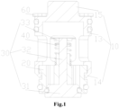
Fig. 1 illustrates a schematic structural diagram of a one-way valve provided in an embodiment of the present disclosure; -
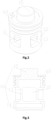
Fig. 2 illustrates a schematic structural diagram of a plugging portion in the one-way valve inFig. 1 ; -
Fig. 3 illustrates a cross-sectional view of the plugging portion inFig. 2 ; -
Fig. 4 illustrates a schematic diagram of an assembly structure of a valve body and a piston portion inFig. 1 ; -
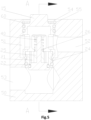
Fig. 5 illustrates a schematic structural diagram of a valve terminal provided in another embodiment of the present disclosure; and -
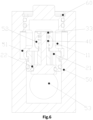
Fig. 6 illustrates a cross-sectional view of the valve terminal inFig. 5 at a position A-A. - The above drawings include the following reference signs:
10. plugging portion; 11. flow cavity; 12. flow port; 13. main body; 14. riveting ring; 15. boss; 20. valve body; 21. overflow hole; 22. valve port; 23. annular groove; 24. cylinder; 25. guide sleeve; 26. guide hole; 30. piston portion; 31.piston head; 32. piston shaft; 33. limiting cap; 40. elastic member; 50. valve seat; 51. accommodating cavity; 52. input flow channel; 53. output flow channel; 54. opening; 55. limiting groove; 60. baffle ring. - A clear and complete description of technical solutions in the embodiments of the present disclosure will be given below, in combination with the drawings in the embodiments of the present disclosure. Apparently, the embodiments described below are merely a part, but not all, of the embodiments of the present disclosure. The following description of at least one exemplary embodiment is merely illustrative in nature and is in no way intended as any limitation on the present disclosure and its disclosure or use. All of other embodiments, obtained by those ordinary skilled in the art based on the embodiments in the present disclosure without any creative effort, fall into the protection scope of the present disclosure.
- As shown in
Fig. 1 to Fig. 4 , an embodiment of the present disclosure provides a one-way valve, including: aplugging portion 10, which is provided with aflow cavity 11 and at least oneflow port 12 communicating with theflow cavity 11; avalve body 20, which is connected with theplugging portion 10, wherein thevalve body 20 is provided with anoverflow hole 21 and avalve port 22 communicating with theoverflow hole 21, and theoverflow hole 21 communicates with theflow cavity 11; apiston portion 30, which includes apiston head 31, apiston shaft 32 and alimiting cap 33, which are connected in sequence, wherein thepiston shaft 32 passes through thevalve body 20, thepiston head 31 is located on a side of thevalve body 20 that is away from theflow cavity 11, thelimiting cap 33 is located inside theflow cavity 11, and thepiston head 31 is movably disposed to plug or open thevalve port 22; and anelastic member 40, which is disposed inside theflow cavity 11, wherein a first end of theelastic member 40 abuts against thevalve body 20, and a second end of theelastic member 40 abuts against the limitingcap 33. - In the present embodiment, the
plugging portion 10 is provided with theflow cavity 11 for enabling fluid to flow, and theflow port 12 communicating with theflow cavity 11, theoverflow hole 21 on thevalve body 20 communicates with theflow cavity 11, thevalve body 20 further includes thevalve port 22 communicating with theoverflow hole 21, and theflow cavity 11 communicates with thevalve port 22 by theoverflow hole 21, so as to form a path. Thepiston shaft 32 of thepiston portion 30 passes through thevalve body 20 and is disposed in theoverflow hole 21 in a penetrating manner, and thepiston head 31 is located on the side of thevalve body 20 that is away from theflow cavity 11, so that thevalve port 22 is sealed by thepiston head 31. Theelastic member 40 is disposed in theflow cavity 11, the first end of the elastic member abuts against thevalve body 20, and the second end of the elastic member abuts against thelimiting cap 33. By an action of theelastic member 40 and the fluid, thepiston head 31 moves to plug or open thevalve port 22, so that an inside of the one-way valve is connected with or disconnected from an external flow channel by thevalve port 22. - By using the solution, portions used for plugging redundant openings of a valve terminal are set to be the plugging
portion 10 and thevalve body 20, which are independent of each other, and are respectively processed, so that parts such as thepiston portion 30 is able to be firstly installed on thevalve body 20, and then thevalve body 20 and the pluggingportion 10 are connected together, thereby avoiding performing an assembly operation in anarrow flow port 12, and thus facilitating an assembly of the one-way valve having a plugging function. - In some embodiments, at least a part of the
piston head 31 is located outside thevalve body 20. In this way, a decrease in the sealing capacity is able to be avoided due to that the portion of thepiston head 31 used for plugging thevalve port 22 is excessively squeezed, thereby improving the strength of the portion and ensuring the sealing capacity of thepiston head 31. - In some embodiments, in a radial direction of the
piston shaft 32, a size of the limitingcap 33 is greater than that of thepiston shaft 32, so that theelastic member 40 is able to conveniently abut against the limitingcap 33, an end of thepiston portion 30 that is close to the limitingcap 33 is limited, and thus the movement of theentire piston portion 30 is controlled by the limitingcap 33 connected with thepiston shaft 32. - In some embodiments, an orientation of the
valve port 22 is perpendicular to an orientation of theflow port 12, and a fluid perpendicularly flows into thevalve port 22 after entering theflow port 12 to form a path. In this way, a fluid reversing requirement under some working conditions is able to be met. - In some embodiments, the
piston head 31 and thepiston shaft 32 are of an integrated structure, and the limitingcap 33 is fixedly connected with thepiston shaft 32; or, in another embodiment not shown in the figures, the limitingcap 33 and thepiston shaft 32 are of an integrated structure, and thepiston head 31 is fixedly connected with thepiston shaft 32. - As shown in
Fig. 1 andFig. 4 , thepiston head 31 and thepiston shaft 32 are made into an integrated structure, thereby being simple to process and convenient to use. Then, the limitingcap 33 is fixedly connected with thepiston shaft 32, so that thepiston head 31, thepiston shaft 32 and the limitingcap 33 are connected into an entirety. In this way, a connection between the limitingcap 33 and thepiston shaft 32 is reliable, and the strength is high. Therefore, compared with a mode in which a snap spring is used, fall or deformation is unlikely to occur. - In some embodiments, a fixed connection is divided into a plurality of modes, including welding, interference fit and the like. The welding fixed connection mode is more stable in connection, and does not require the cooperation of other accessories.
- In some embodiments, the plugging
portion 10 is riveted, clamped, or welded with thevalve body 20. Thevalve body 20 and the pluggingportion 10 are connected and then are placed in the valve terminal as a whole, so that an assembly or disassembly is more convenient, and an overall structure of the one-way valve is also more stable and reliable. - As shown in
Fig. 1 , the pluggingportion 10 is riveted with thevalve body 20, an outer wall of thevalve body 20 is provided with anannular groove 23, the pluggingportion 10 includes amain body 13 and ariveting ring 14 disposed on themain body 13, themain body 13 is provided with theflow cavity 11 and theflow port 12, a wall thickness of theriveting ring 14 is less than that of themain body 13, and an end portion of theriveting ring 14 is clamped into theannular groove 23 through riveting. - In the present embodiment, the end portion of the
riveting ring 14 is clamped into theannular groove 23 through riveting, the end portion of theriveting ring 14 is first moved to the position of theannular groove 23, and then the end portion of theriveting ring 14 is radially contracted by using a tool, so as to abut against an inner wall of theannular groove 23 to realize riveting, so that thevalve body 20 and the pluggingportion 10 are connected into an entirety. Theflow cavity 11 and theflow port 12 are disposed on themain body 13 in the pluggingportion 10 for communicating the flow channel and theflow cavity 11, so as to ensure smooth flow of the fluid. - In some embodiments, an end face of the
main body 13 abuts against an end face of thevalve body 20. In this way, the pluggingportion 10 where thevalve body 20 and themain body 13 are located is able to be further limited in an axial direction, thereby improving the structural stability. - As shown in
Fig. 1 to Fig. 3 , the pluggingportion 10 further includes aboss 15, and theboss 15 is disposed on a side of themain body 13 that faces away from thevalve body 20; and there are a plurality offlow ports 12, and the plurality offlow ports 12 are disposed at intervals in a circumferential direction of themain body 13. An upper end of the pluggingportion 10 is provided with theboss 15, when the pluggingportion 10 is mounted or dismounted, theboss 15 may be held in a hand or theboss 15 is matched with an accessory for operation, so as to place the entire one-way valve into anopening 54 or take out same from theopening 54 more conveniently. The plurality offlow ports 12 on themain body 13 are disposed at intervals in the circumferential direction, so as to prevent the situation that theflow ports 12 cannot communicate with the flow channel caused by that theflow ports 12 are misplaced during a placement process due to a sealed and invisible structure. By providing the plurality offlow ports 12, during the process of disposing the one-way valve in the valve terminal, when the one-way valve is rotated by any angle in the circumferential direction for placement, it is able to be ensured that theflow ports 12 communicate with the flow channel. - In some embodiments, the
valve body 20 includes: acylinder 24, wherein theoverflow hole 21 is located inside thecylinder 24; aguide sleeve 25, which is disposed in theoverflow hole 21, wherein theguide sleeve 25 is provided with aguide hole 26, and thepiston shaft 32 movably passes through theguide hole 26; and a plurality of support beams, wherein two ends of each support beam are respectively connected with theguide sleeve 25 and thecylinder 24. - In the present embodiment, the
valve body 20 includes thecylinder 24, theguide sleeve 25 and the plurality of support beams, the two ends of the plurality of support beams are respectively connected with theguide sleeve 25 and thecylinder 24, thereby ensuring the stability of the overall structure; and moreover, the position of theguide sleeve 25 may be fixed, and theguide sleeve 25 is provided with theguide hole 26 for passing through thepiston shaft 32, thereby guiding thepiston shaft 32, and preventing thepiston shaft 32 from inclining to cause thepiston part 30 to incline. - In some embodiments, the
piston head 31 is provided with a first sealing groove, thepiston portion 30 further includes a first sealing ring, and the first sealing ring is disposed in the first sealing groove; an outer wall of thevalve body 20 is provided with a second sealing groove, the one-way valve further includes a second sealing ring, and the second sealing ring is disposed in the second sealing groove; and an outer wall of the pluggingportion 10 is provided with a third sealing groove, the one-way valve further includes a third sealing ring, and the third sealing ring is disposed in the third sealing groove. By providing a plurality of sealing grooves, the sealing performance of the one-way valve is able to be ensured to avoid the leakage of the fluid. - In another embodiment provided in the present disclosure, which is not shown in the figures, different from the above embodiment, the plugging
portion 10 is clamped with thevalve body 20, wherein the pluggingportion 10 is provided with a clamping groove, thevalve body 20 is provided with a buckle, and the buckle is clamped into the clamping groove; or, the pluggingportion 10 is provided with a buckle, thevalve body 20 is provided with a clamping groove, and the buckle is clamped into the clamping groove. In the present embodiment, the clamping groove is formed in the pluggingportion 10, and the buckle is disposed on thevalve body 20; or, the clamping groove is formed in thevalve body 20, the buckle is disposed on the pluggingportion 10, and thevalve body 20 and the pluggingportion 10 are fixed together by a snap fit of the clamping groove and the buckle, so as to form an entirety, thereby improving the reliability of the overall connection. - As shown in
Fig. 5 andFig. 6 , according to a yet another embodiment provided in the present disclosure, provided is a valve terminal, the valve terminal includes avalve seat 50 and the above one-way valve, thevalve seat 50 is provided with anaccommodating cavity 51, and aninput flow channel 52 and anoutput flow channel 53, which are disposed at intervals, theinput flow channel 52 communicates with theaccommodating cavity 51, the one-way valve is disposed in theaccommodating cavity 51, theaccommodating cavity 51 communicates with theflow port 12 of the one-way valve, and thevalve port 12 of the one-way valve communicates with theoutput flow channel 53 in a connectable/disconnectable mode. - In the present embodiment, the
valve seat 50 is internally provided with theaccommodating cavity 51, the one-way valve is disposed in theaccommodating cavity 51, thevalve seat 50 is further provided with theinput flow channel 52 and theoutput flow channel 53, which are disposed at intervals and communicate with theaccommodating cavity 51, thevalve port 22 of the one-way valve communicates with theoutput flow channel 53 in the connectable/disconnectable mode, and theflow port 12 communicates with theaccommodating cavity 51 to form a flow channel path. The fluid flows in and sequentially passes through theinput flow channel 52, theaccommodating cavity 51, theflow port 12, theflow cavity 11, theoverflow hole 21, thevalve port 22 and theoutput flow channel 53. - During inflow, the fluid first flows through the
input flow channel 52, at this time, the one-way valve is in a closed state, the fluid enters theaccommodating cavity 51 and flows into theflow cavity 11 through the plurality offlow ports 12 on a side surface of themain body 13, the fluid continues to flow downwards to enter theoverflow hole 21, so as to push thepiston head 31 to move downwards, theelastic member 40 contracts to open thevalve port 22, so that the one-way valve is in an avoidance state, and the fluid flows into theoutput flow channel 53 from thevalve port 22, so as to form a path; and when the pressure of the fluid is decreased, theelastic member 40 in a contracted state is stretched and unfolded to pull thepiston head 31 abutting against theelastic member 40 to move upwards, so as to close thevalve port 22, so that the one-way valve is in the closed state, and after the fluid flows into theinput flow channel 52, a path cannot be formed since thevalve port 22 is closed, and accordingly the flow channel of the fluid is plugged. - In some embodiments, the
input flow channel 52 and theoutput flow channel 53 are disposed in parallel, theaccommodating cavity 51 is provided with anopening 54, an inner wall of theopening 54 is provided with a limitinggroove 55, the one-way valve may be taken out or installed in theaccommodating cavity 51 from theopening 54, the valve terminal further includes abaffle ring 60, thebaffle ring 60 is detachably clamped into the limitinggroove 55, and thebaffle ring 60 is in stop fit with the pluggingportion 10 of the one-way valve. In the present embodiment, theaccommodating cavity 51 is provided with theopening 54, which is formed in an upper end of theaccommodating cavity 51 and is used for assembling the one-way valve. In this way, the processing of the flow channels and the installation and removal of the one-way valve are facilitated. Meanwhile, the one-way valve extends into theaccommodating cavity 51 from theopening 54 to plug theopening 54, so that a flow direction of the fluid inside the valve terminal is not affected. The valve terminal further includes thebaffle ring 60, thebaffle ring 60 is detachably clamped into the limitinggroove 55 on the inner wall of theopening 54, and thebaffle ring 60 is in stop fit with the pluggingportion 10, thereby preventing the one-way valve from moving up and down due to an excessive fluid impact of theinput flow channel 52 during a working process of the valve terminal. - The above descriptions are only some embodiments of the present disclosure, and are not intended to limit the present disclosure. For those skilled in the art, the present disclosure may have various modifications and changes. Any modifications, equivalent replacements, improvements and the like, made within the spirit and principles of the present disclosure, shall be included within the protection scope of the present disclosure.
Claims (10)
- A one-way valve, comprising:a plugging portion (10), which is provided with a flow cavity (11) and at least one flow port (12) communicating with the flow cavity (11);a valve body (20), which is connected with the plugging portion (10), wherein the valve body (20) is provided with an overflow hole (21) and a valve port (22) communicating with the overflow hole (21), and the overflow hole (21) communicates with the flow cavity (11);a piston portion (30), which comprises a piston head (31), a piston shaft (32) and a limiting cap (33), which are connected in sequence, wherein the piston shaft (32) passes through the valve body (20), the piston head (31) is located on a side of the valve body (20) that is away from the flow cavity (11), the limiting cap (33) is located inside the flow cavity (11), and the piston head (31) is movably disposed to plug or open the valve port (22); andan elastic member (40), which is disposed inside the flow cavity (11), wherein a first end of the elastic member (40) abuts against the valve body (20), and a second end of the elastic member (40) abuts against the limiting cap (33).
- The one-way valve according to claim 1, wherein,the piston head (31) and the piston shaft (32) are of an integrated structure, and the limiting cap (33) is fixedly connected with the piston shaft (32); or,the limiting cap (33) and the piston shaft (32) are of an integrated structure, and the piston head (31) is fixedly connected with the piston shaft (32).
- The one-way valve according to claim 1, wherein the plugging portion (10) is riveted, clamped, or welded with the valve body (20).
- The one-way valve according to claim 3, wherein the plugging portion (10) is riveted with the valve body (20), an outer wall of the valve body (20) is provided with an annular groove (23), the plugging portion (10) comprises a main body (13) and a riveting ring (14) disposed on the main body (13), the main body (13) is provided with the flow cavity (11) and the flow port (12), a wall thickness of the riveting ring (14) is less than a wall thickness of the main body (13), and an end portion of the riveting ring (14) is clamped into the annular groove (23) through riveting.
- The one-way valve according to claim 4, wherein the plugging portion (10) further comprises a boss (50), and the boss (50) is disposed on a side of the main body (13) that is away from the valve body (20); and there are a plurality of flow ports (12), and the plurality of flow ports (12) are disposed at intervals in a circumferential direction of the main body (13).
- The one-way valve according to claim 1, wherein the plugging portion (10) is clamped with the valve body (20);the plugging portion (10) is provided with a clamping groove, the valve body (20) is provided with a buckle, and the buckle is clamped into the clamping groove; or,the plugging portion (10) is provided with a buckle, the valve body (20) is provided with a clamping groove, and the buckle is clamped into the clamping groove.
- The one-way valve according to claim 1, wherein the valve body (20) comprises:a cylinder (24), the overflow hole (21) being located inside the cylinder (24);a guide sleeve (25), which is disposed in the overflow hole (21), the guide sleeve (25) being provided with a guide hole, and the piston shaft (32) movably passing through the guide hole; anda plurality of support beams, two ends of each support beam being respectively connected with the guide sleeve (25) and the cylinder (24).
- The one-way valve according to claim 1, wherein,the piston head (31) is provided with a first sealing groove, the piston portion (30) further comprises a first sealing ring, and the first sealing ring is disposed in the first sealing groove;an outer wall of the valve body (20) is provided with a second sealing groove, the one-way valve further comprises a second sealing ring, and the second sealing ring is disposed in the second sealing groove; andan outer wall of the plugging portion (10) is provided with a third sealing groove, the one-way valve further comprises a third sealing ring, and the third sealing ring is disposed in the third sealing groove.
- A valve terminal, wherein the valve terminal comprises a valve seat (50) and the one-way valve according to any one of claims 1-8, the valve seat (50) is provided with an accommodating cavity (51), and an input flow channel (52) and an output flow channel (53), which are disposed at intervals, the input flow channel (52) communicates with the accommodating cavity (51), the one-way valve is disposed in the accommodating cavity (51), the accommodating cavity (51) communicates with the flow port (12) of the one-way valve, and the valve port (22) of the one-way valve communicates with the output flow channel (53) in a connectable/disconnectable mode.
- The valve terminal according to claim 9, wherein the input flow channel (52) and the output flow channel (53) are disposed in parallel, the accommodating cavity (51) is provided with an opening (54), an inner wall of the opening (54) is provided with a limiting groove (55), the one-way valve is able to be taken out or installed in the accommodating cavity (51) from the opening (54), the valve terminal further comprises a baffle ring (60), the baffle ring (60) is detachably clamped into the limiting groove (55), and the baffle ring (60) is in stop fit with the plugging portion (10) of the one-way valve.
Applications Claiming Priority (2)
| Application Number | Priority Date | Filing Date | Title |
|---|---|---|---|
| CN202121607681.XU CN215806542U (en) | 2021-07-14 | 2021-07-14 | One-way valve and valve terminal |
| PCT/CN2022/105217 WO2023284744A1 (en) | 2021-07-14 | 2022-07-12 | One-way valve and valve island |
Publications (2)
| Publication Number | Publication Date |
|---|---|
| EP4372256A1 true EP4372256A1 (en) | 2024-05-22 |
| EP4372256A4 EP4372256A4 (en) | 2024-11-06 |
Family
ID=80182147
Family Applications (1)
| Application Number | Title | Priority Date | Filing Date |
|---|---|---|---|
| EP22841379.5A Pending EP4372256A4 (en) | 2021-07-14 | 2022-07-12 | One-way valve and valve island |
Country Status (4)
| Country | Link |
|---|---|
| US (1) | US20240318736A1 (en) |
| EP (1) | EP4372256A4 (en) |
| CN (1) | CN215806542U (en) |
| WO (1) | WO2023284744A1 (en) |
Families Citing this family (4)
| Publication number | Priority date | Publication date | Assignee | Title |
|---|---|---|---|---|
| EP4144603A4 (en) * | 2020-04-30 | 2024-05-29 | Hitachi Astemo Ueda Co., Ltd. | Check valve and brake system |
| CN215806542U (en) * | 2021-07-14 | 2022-02-11 | 盾安汽车热管理科技有限公司 | One-way valve and valve terminal |
| CN220980404U (en) * | 2023-09-28 | 2024-05-17 | 盾安汽车热管理科技有限公司 | One-way valve |
| WO2025162080A1 (en) * | 2024-02-02 | 2025-08-07 | 浙江盾安人工环境股份有限公司 | One-way valve |
Family Cites Families (8)
| Publication number | Priority date | Publication date | Assignee | Title |
|---|---|---|---|---|
| JPS5942191B2 (en) * | 1981-12-25 | 1984-10-13 | 東陶機器株式会社 | Hot water mixing faucet |
| JP5004568B2 (en) * | 2006-12-06 | 2012-08-22 | 不二ラテックス株式会社 | shock absorber |
| DE102011006601A1 (en) * | 2011-03-31 | 2012-10-04 | Schaeffler Technologies Gmbh & Co. Kg | Hydraulic absorbed clamping apparatus used in traction drive of combustion engine for vehicle, has valve holder provided with sealing seat that is co-operated with valve portion of pressure-dependent poppet valve |
| CN205224205U (en) * | 2015-12-15 | 2016-05-11 | 黄河 | Self -imposed flashing valve of push type |
| JP6636344B2 (en) * | 2016-01-22 | 2020-01-29 | 太平洋工業株式会社 | Valve core |
| CN211599638U (en) * | 2019-12-30 | 2020-09-29 | 上海索菲玛汽车滤清器有限公司 | One-way valve |
| CN212564562U (en) * | 2020-09-11 | 2021-02-19 | 新昌县丰亿电器有限公司 | Valve seat and piston type check valve |
| CN215806542U (en) * | 2021-07-14 | 2022-02-11 | 盾安汽车热管理科技有限公司 | One-way valve and valve terminal |
-
2021
- 2021-07-14 CN CN202121607681.XU patent/CN215806542U/en active Active
-
2022
- 2022-07-12 WO PCT/CN2022/105217 patent/WO2023284744A1/en not_active Ceased
- 2022-07-12 EP EP22841379.5A patent/EP4372256A4/en active Pending
- 2022-07-12 US US18/578,743 patent/US20240318736A1/en active Pending
Also Published As
| Publication number | Publication date |
|---|---|
| US20240318736A1 (en) | 2024-09-26 |
| CN215806542U (en) | 2022-02-11 |
| EP4372256A4 (en) | 2024-11-06 |
| WO2023284744A1 (en) | 2023-01-19 |
Similar Documents
| Publication | Publication Date | Title |
|---|---|---|
| EP4372256A1 (en) | One-way valve and valve island | |
| EP3974689B1 (en) | Electronic expansion valve | |
| CN217301817U (en) | Pilot-operated electromagnetic valve | |
| CN217301743U (en) | One-way valve | |
| KR102937116B1 (en) | solenoid valve | |
| US20250251071A1 (en) | Fluid connector and female-end valve stem, female-end structure, and male-end piston thereof | |
| JP5791906B2 (en) | Fluid connector | |
| US20180252212A1 (en) | Cartridge vane pump | |
| CN209925712U (en) | Hydrogenation machine that can repeat installation fast is with breaking valve | |
| WO2025067547A1 (en) | Check valve | |
| US12117217B1 (en) | Gas-liquid separator and compression system | |
| US20180258928A1 (en) | Cartridge vane pump | |
| WO2024193296A1 (en) | Piston structure and reversing valve | |
| CN210034488U (en) | Valve core and air gun | |
| CN214368424U (en) | Fastening-releasing pipe joint | |
| KR100537777B1 (en) | One-touch tube connector | |
| EP4417843A1 (en) | Stop valve, machining method, and assembly method | |
| CN111561435B (en) | Handheld double-tube single-connection electric hydraulic pump | |
| CN211975889U (en) | Pilot-operated overflow valve | |
| CN215806543U (en) | One-way valve and valve terminal | |
| CN220749130U (en) | One-way throttle combination valve | |
| CN220134693U (en) | Throttle seal assembly and throttle valve | |
| CN110081195B (en) | Valve core and gas gun | |
| CN116928400A (en) | One-way valve | |
| JP6424813B2 (en) | Compressor check valve |
Legal Events
| Date | Code | Title | Description |
|---|---|---|---|
| STAA | Information on the status of an ep patent application or granted ep patent |
Free format text: STATUS: THE INTERNATIONAL PUBLICATION HAS BEEN MADE |
|
| PUAI | Public reference made under article 153(3) epc to a published international application that has entered the european phase |
Free format text: ORIGINAL CODE: 0009012 |
|
| STAA | Information on the status of an ep patent application or granted ep patent |
Free format text: STATUS: REQUEST FOR EXAMINATION WAS MADE |
|
| 17P | Request for examination filed |
Effective date: 20240119 |
|
| AK | Designated contracting states |
Kind code of ref document: A1 Designated state(s): AL AT BE BG CH CY CZ DE DK EE ES FI FR GB GR HR HU IE IS IT LI LT LU LV MC MK MT NL NO PL PT RO RS SE SI SK SM TR |
|
| DAV | Request for validation of the european patent (deleted) | ||
| DAX | Request for extension of the european patent (deleted) | ||
| A4 | Supplementary search report drawn up and despatched |
Effective date: 20241004 |
|
| RIC1 | Information provided on ipc code assigned before grant |
Ipc: F16K 15/02 20060101ALI20240927BHEP Ipc: F16K 17/04 20060101ALI20240927BHEP Ipc: F16K 15/06 20060101AFI20240927BHEP |