EP4372237A1 - Screw boss - Google Patents
Screw boss Download PDFInfo
- Publication number
- EP4372237A1 EP4372237A1 EP22207891.7A EP22207891A EP4372237A1 EP 4372237 A1 EP4372237 A1 EP 4372237A1 EP 22207891 A EP22207891 A EP 22207891A EP 4372237 A1 EP4372237 A1 EP 4372237A1
- Authority
- EP
- European Patent Office
- Prior art keywords
- rib
- screwboss
- main body
- opening
- base
- Prior art date
- Legal status (The legal status is an assumption and is not a legal conclusion. Google has not performed a legal analysis and makes no representation as to the accuracy of the status listed.)
- Granted
Links
Images

Classifications
-
- F—MECHANICAL ENGINEERING; LIGHTING; HEATING; WEAPONS; BLASTING
- F16—ENGINEERING ELEMENTS AND UNITS; GENERAL MEASURES FOR PRODUCING AND MAINTAINING EFFECTIVE FUNCTIONING OF MACHINES OR INSTALLATIONS; THERMAL INSULATION IN GENERAL
- F16B—DEVICES FOR FASTENING OR SECURING CONSTRUCTIONAL ELEMENTS OR MACHINE PARTS TOGETHER, e.g. NAILS, BOLTS, CIRCLIPS, CLAMPS, CLIPS OR WEDGES; JOINTS OR JOINTING
- F16B29/00—Screwed connection with deformation of nut or auxiliary member while fastening
-
- F—MECHANICAL ENGINEERING; LIGHTING; HEATING; WEAPONS; BLASTING
- F16—ENGINEERING ELEMENTS AND UNITS; GENERAL MEASURES FOR PRODUCING AND MAINTAINING EFFECTIVE FUNCTIONING OF MACHINES OR INSTALLATIONS; THERMAL INSULATION IN GENERAL
- F16B—DEVICES FOR FASTENING OR SECURING CONSTRUCTIONAL ELEMENTS OR MACHINE PARTS TOGETHER, e.g. NAILS, BOLTS, CIRCLIPS, CLAMPS, CLIPS OR WEDGES; JOINTS OR JOINTING
- F16B5/00—Joining sheets or plates, e.g. panels, to one another or to strips or bars parallel to them
- F16B5/02—Joining sheets or plates, e.g. panels, to one another or to strips or bars parallel to them by means of fastening members using screw-thread
-
- F—MECHANICAL ENGINEERING; LIGHTING; HEATING; WEAPONS; BLASTING
- F16—ENGINEERING ELEMENTS AND UNITS; GENERAL MEASURES FOR PRODUCING AND MAINTAINING EFFECTIVE FUNCTIONING OF MACHINES OR INSTALLATIONS; THERMAL INSULATION IN GENERAL
- F16B—DEVICES FOR FASTENING OR SECURING CONSTRUCTIONAL ELEMENTS OR MACHINE PARTS TOGETHER, e.g. NAILS, BOLTS, CIRCLIPS, CLAMPS, CLIPS OR WEDGES; JOINTS OR JOINTING
- F16B25/00—Screws that cut thread in the body into which they are screwed, e.g. wood screws
-
- F—MECHANICAL ENGINEERING; LIGHTING; HEATING; WEAPONS; BLASTING
- F16—ENGINEERING ELEMENTS AND UNITS; GENERAL MEASURES FOR PRODUCING AND MAINTAINING EFFECTIVE FUNCTIONING OF MACHINES OR INSTALLATIONS; THERMAL INSULATION IN GENERAL
- F16B—DEVICES FOR FASTENING OR SECURING CONSTRUCTIONAL ELEMENTS OR MACHINE PARTS TOGETHER, e.g. NAILS, BOLTS, CIRCLIPS, CLAMPS, CLIPS OR WEDGES; JOINTS OR JOINTING
- F16B25/00—Screws that cut thread in the body into which they are screwed, e.g. wood screws
- F16B25/001—Screws that cut thread in the body into which they are screwed, e.g. wood screws characterised by the material of the body into which the screw is screwed
- F16B25/0015—Screws that cut thread in the body into which they are screwed, e.g. wood screws characterised by the material of the body into which the screw is screwed the material being a soft organic material, e.g. wood or plastic
Definitions
- the present disclosure relates to a screwboss, i.e. a boss for a self-tapping screw, featuring a pilot hole into which a self-tapping screw may be screwed to hold a component in place.
- a screwboss is a common solution to ensure correct positioning of a metal self-tapping screw into a plastic hole.
- a typical example of a screwboss alternatively termed a screw post or stalk, comprises a cylindrical body made from a deformable plastics material with a hole (e.g. a blind bore) formed at its central axis to receive a self-tapping screw.
- the body is formed to be upstanding from and integral with a support surface/base and may include two or more ribs radiating from the central axis that provide additional stability for mitigating lateral movement and absorbing twisting forces applied to the body relative to its support surface while a screw is turning into the hole.
- one or more separate component elements may be secured by virtue of their own through holes aligning with that of the screwboss and a self-tapping screw compatible with the hole dimensions being introduced through both the component (s) and into the boss.
- a harder material e.g. metal
- the screw thread bites into the plastic inner wall of the hole and is drawn thereinto.
- the hole may have surface features (e.g. bevels/internal ribs) for guiding the screw or be relatively smooth, but it is always deeper than the length of the screw, so as it accommodate the screw shaft fully up to its head when components are in place.
- the deformable wall of the hole/body may marginally expand to accommodate the screw, further reinforced by the radial ribs.
- a screwboss serves to separate component surfaces by virtue of its body height and mounts said components securely in place, often for the lifetime of the assembled product.
- a self-tapping screw is removable by turning in a reverse direction of the screw thread and thereby withdrawing it from the hole. As such, component elements of a product can be disassembled if required.
- a screwboss is subject to torsion forces as the self-tapping screw is engaged. Design of the screwboss must therefore account for being able to withstand these forces, traded off against material (e.g. plastics, alloy, aluminium) use in manufacturing the component. Particularly, the relative resilience of the screwboss to torsion forces will affect the speed at which a screw can be screwed into its hole, thereby having an impact on the overall cycle time for assembling a component/product, which may have multiple screwbosses integrated therewith.
- Ribs are provided as a support structure and also contribute reinforced strength to the boss and its ability to expand to accommodate a screw. It is known to skilled persons that if an excessive torque force is applied, e.g. due to high speed screwing, then a screwboss can fail.
- the present invention seeks to address shortcomings associated with known screwboss structures and proposes an improvement, particularly a solution that may enable a reduction in cycle time/increase in turning speed of a screw for an equivalent or reduced materials usage during manufacture.
- a screwboss may be comprised of: a base; a main body, upstanding from the base, having an external sidewall and an opening for fixing a screw threaded element thereinto; and a plurality of ribs, each spanning between / adjoining the base and main body; wherein at least one rib of the plurality of ribs extends from a location on the external sidewall parallel with but angularly offset from a normal radial line taken from a centre of the opening.
- the offset may be at least a half thickness of a rib from the radial line.
- the rib at the point it is connected to the boss sidewall, is preferably positioned to extend parallel to the radial line offset toward (which includes coinciding with or beyond) a parallel tangent line from the opening for fixing a screw, so as to be offset from the normal radial line it is parallel with.
- the screwboss of the invention has the effect of providing an alternative rib location to better accommodate the torque forces created by self-tapping screws and, hence, enable a potentially increased speed of screwing.
- the problem of slow cycle time during screwing into plastic is solved, e.g. by offsetting where a rib is attached to the body to be located to one side of an imaginary radial line taken from the hole/boss centre, exactly where the forces distributed during self-tapping are found.
- ribs are located at a place where forces are best distributed in order to correctly enforce the screwing process.
- the boss body maintains a freedom to expand while reinforced by the ribs, thereby resulting in decreased cycle time and/or reduced chance of breakage/failure of the boss.
- supporting ribs are arranged radially in a uniform cross configuration from a centre of the screw-hole, whereas ribs of the invention are offset from that normal radial position taken from a centre of the fixing opening.
- the offset may be either counter-clockwise or clockwise.
- the rib offset from a normal radial line is counter/anti-clockwise, to account for a clockwise screw direction as is most common.
- the configuration would be reversed to a clockwise offset for an intended lefthand screw direction.
- an entire thickness of a rib is outside the radial line from the centre, but at least begins parallel thereto.
- a rib thickness may be approximately equal to a diameter of the opening, but any suitable dimensions are contemplated.
- Each rib is typically of a uniform shape with other ribs, but different rib configurations/shapes are possible.
- a rib may be configured to taper outwardly from a connecting position at the body's sidewall distant from the base, toward the base. In other words, the ribs are wider where connected at the base than where connected further up the main body. Outward tapering of a rib may be either in the longitudinal direction of the upstanding body or radially from the body, or both. In the case of a radial taper or draft angle design, reinforcement at upper portions of the boss is minimised for less resistance to screw forces, compared to at the base where the upstanding main body must be supported from breaking off laterally during finalisation of the screw cycle and for a lifetime of the assembled product. Torque is greatest at the end of the cycle where a screw head abuts the main body and is prevented from further entry into the hole.
- a height of the main body may be determined by assembly parameters, particularly the length of screw that is to be inserted/fixed into the hole.
- the depth of receiving hole is preferably beyond total invasive length of a screw shaft, taking into account the thickness of component elements secured to the boss.
- the screwboss is formed in one piece such that the base, body and ribs are integrally formed and made from a continuous piece of material, e.g. by injection moulding, however, co-moulding or other manufacturing methods may be possible.
- the screw boss may be formed from plastics, metal (e.g. aluminium) or other flowable/mouldable material.
- the screwboss may be aligned for mounting and securing various components or sandwiches of multiple components, e.g. a PCB alone or with a cover plate, that is screwed to a base component which featuring an upstanding screwboss according to the invention.
- an upstanding leading edge of an outside face of the rib where it is connected to the side wall, extends approximately 45 degrees from an imaginary line normal to the sidewall, to optimally provide support resisting the torque force applied by a turning screw during assembly and for a final torque applied to hold components in place.
- such a configuration is able to accommodate faster screwing speeds at the beginning and during the screwing cycle for the same material use as conventional radial ribs.
- a plane (e.g. a central plane) of the rib is approximately tangential to an edge of the screw-receiving opening or between a tangent of the opening and a tangent of the main body.
- at least part of the thickness of the rib, where it connects with the boss side wall is tangential or overlaps with a tangential line from the opening.
- the invention is embodied by a screwboss comprised of: a base; a main body; an opening into an end of the main body, distal from the base, for fixing a threaded fastener thereinto; and at least one rib, adjoining the base and main body, to support the main body in an upstanding position; wherein the at least one rib extends from the main body at a position in line with a tangent line from the opening.
- the rib position should be interpreted as anywhere between a tangent line from the opening to a tangent line of the main body.
- the tangent line coincides within a thickness of the at least one rib.
- the at least one rib is parallel and offset to the side of a radial line extending from a centre of the opening.
- the at least one rib is tapered inwardly in a longitudinal direction from the base toward the main body.
- the at least one rib may extend outwardly from the main body, with a draft angle.
- the at least one rib may comprise a plurality of ribs, each at a position in line with a tangent line from the opening.
- Each rib of the plurality of ribs may radiate at an even spacings about the main body.
- the screwboss is configured for a right hand screw threaded fastener, wherein the at least one rib is offset in a counter-clockwise direction from the radial line.
- the at least one rib is offset far enough so as not to overlap with the radial line.
- the invention extends to a component incorporating a screwboss according to any desirable feature herein, e.g. configured for use in assembly of a vehicle.
- the invention further extends to a method for mounting a first component part to a base component part, according to claim 12, e.g. in a vehicle.
- ribs Preferably there are four ribs, however, the solution may suffice with one rib, especially if the boss body is set into the corner of a component. Two, three or five or more ribs may also be appropriate depending on space constraints and scale of the boss.
- a screwboss is provided where each of a plurality of ribs is parallel with but offset from a directly radial line taken from a centre of the screw boss.
- the invention is applicable not just to self-tapping screws but also threaded members such as bolts. In these cases, a corresponding thread may be tapped/moulded into the receiving hole. Torque forces are still developed in such an arrangement, especially at the end of the cycle when a fastener may be set at a desired torque to hold a component in place.
- Screwboss 10 is generally comprised of a base 11 (which will in practice be part of a larger component element than that illustrated), an upstanding main body 12 and a plurality of ribs 13.
- main body 12 is generally cylindrical in shape, although it may have other elongate forms, and features a central opening 14 for receiving a screw fastener.
- the opening has a bevelled edge or annular inset, but otherwise has smooth walls down to a specified depth (e.g. seen in Figure 7 example).
- the opening may be all the way through body 12 and base 11, but is more likely a blind bore that at least leaves an open space beyond the distal end of a screw.
- each rib 13 extends away from a side wall of body 12 in a position that is parallel but offset to a radial line (R) taken from a central axis (X) of the opening/body.
- R radial line
- X central axis
- a desirable position of a rib according to the invention can be described in several ways.
- a central plane P of a rib 13 is shown as parallel to and offset from a radial line R, e.g. by more than half a thickness of rib 13.
- central plane P of rib 13 is substantially tangential to a wall of opening 14 where, in use, a screw fastener would contact the boss body 12 and apply force thereto, e.g. in a clockwise direction assuming a common right hand screw thread.
- a directional force line F is shown in Figure 4 , resulting from a torsion force T caused by rotation of a screw fastener.
- an upstanding leading edge of an outside face of the rib begins approximately 40-70 degrees from the centre axis X of the hole.
- the position of the rib 13 optimally provides support for resisting the torque force F applied by a turning screw during assembly and for a final torque applied to hold a component in place.
- rib 13 is offset to one side of radial line R and not overlapping therewith.
- rib 13 extends from and overlaps with a tangent of opening 14. Any part across the thickness of a rib 13 may coincide with a tangential line from the hole/opening 14.
- the centre plane P coincides with tangential line G.
- Figure 1 features four ribs 13 in the form of right angle triangular wedges, where the right angle corner is located at the join between base 11 and upstanding main body 12.
- the thickness is uniform, although alternative configurations are possible.
- Figure 2 illustrates an alternative embodiment of screw boss 10 where a rib 13 is configured to taper with a draft angle outwardly from the main body 12, toward base 11 where the rib is thickest. Indeed, in some embodiments body 12 may be independently tapered outwardly from the opening end 14 toward the base 11. A draft of the type illustrated may assist with removal from an injection moulding tool, without significantly affecting its strength for accommodating torsion forces. As shown in the plan view of Figure 2 , the positional arrangement of ribs 13 is otherwise analogous to that of Figures 1 , 3 and 4 .
- Figure 5 illustrates a variation of the embodiment of Figure 1 , where the effective upstanding height of body 12 is reduced. However, the function and position of ribs 13 remains the same. Any embodiment of the screwboss may have a height tailored to the length of screw needed for securing a component or to provide clearance or surface features on a component.
- Figure 6 illustrates a variation where substantive external surfaces of the rib 13 are at positions approximately in line with a tangent line G from the opening and a radial line R from the centre axis X respectively.
- rib 13 is generally offset from and parallel with the radial line R, but now with a thickness that is approximately equal to the radius of the opening 14 (i.e. half the diameter). This may exemplify an optimum position for a rib which uses less material but is best positioned for absorbing torque forces from a screw. It is noteworthy that, for all embodiments, a rib begins to extend from a position in line with (i.e.
- a rib could be curved so long as it begins at a tangential position.
- Figure 7 illustrates a cross section view of an assembled product/component where a (e.g. self-tapping) screw fastener, having a threaded shaft 15 and head 16, has been driven into the blind hole 14 of a boss body 12.
- Head 16 is generally rotated into engagement by a tool at a predetermined torque force, where shaft 15 passes through aligned openings of one or more component flanges 17 and 18.
- flange layer 17 e.g. a PCB
- flange layer 17 is mounted in contact with screw boss 12 so as to distance electrical components on its surface from undesirable contact with a base (not shown) of the boss or a cover component 18.
- outwardly extending ribs of the invention are arranged to accommodate the torque force as shaft 15 engages and drives into hole 14 and at conclusion of the screw cycle where head 16 contacts the components (17, 18) being secured.
- Figure 8 illustrates a plan view of base component 11 incorporating a boss 12 and rib structure 13 as described above. Ribs 13 may be incorporated with other strengthening ribs of the base 11. In a case where boss 12 is located in the corner of a component, upstanding side walls extending from base 11 may provide a supporting function with a variation in size and/or number of supporting ribs according to the invention.
- the improved rib structure is configured for mitigating forces applied during driving of a screw into a boss. Cycle time during the screwing process may be reduced. Assuming a similar amount of materials used in constructing the boss 12, heat generation during screwing is expected to remain the same, or a bit higher due to faster screwing.
- the invention is generally embodied by a screwboss comprised of a base and an upstanding main body having an opening at one end thereof.
- a series of ribs are spaced apart about the main body, each at a position offset from a normal radial position, i.e. generally coinciding with (toward, at or beyond) an imaginary tangent line extending from an edge of the opening.
Landscapes
- Engineering & Computer Science (AREA)
- General Engineering & Computer Science (AREA)
- Mechanical Engineering (AREA)
- Connection Of Plates (AREA)
Abstract

Description
- The present disclosure relates to a screwboss, i.e. a boss for a self-tapping screw, featuring a pilot hole into which a self-tapping screw may be screwed to hold a component in place.
- A screwboss is a common solution to ensure correct positioning of a metal self-tapping screw into a plastic hole. A typical example of a screwboss, alternatively termed a screw post or stalk, comprises a cylindrical body made from a deformable plastics material with a hole (e.g. a blind bore) formed at its central axis to receive a self-tapping screw. The body is formed to be upstanding from and integral with a support surface/base and may include two or more ribs radiating from the central axis that provide additional stability for mitigating lateral movement and absorbing twisting forces applied to the body relative to its support surface while a screw is turning into the hole.
- In use, one or more separate component elements may be secured by virtue of their own through holes aligning with that of the screwboss and a self-tapping screw compatible with the hole dimensions being introduced through both the component (s) and into the boss. By virtue of a harder material (e.g. metal) the screw thread bites into the plastic inner wall of the hole and is drawn thereinto. The hole may have surface features (e.g. bevels/internal ribs) for guiding the screw or be relatively smooth, but it is always deeper than the length of the screw, so as it accommodate the screw shaft fully up to its head when components are in place. The deformable wall of the hole/body may marginally expand to accommodate the screw, further reinforced by the radial ribs.
- A screwboss serves to separate component surfaces by virtue of its body height and mounts said components securely in place, often for the lifetime of the assembled product. However, a self-tapping screw is removable by turning in a reverse direction of the screw thread and thereby withdrawing it from the hole. As such, component elements of a product can be disassembled if required.
- A screwboss is subject to torsion forces as the self-tapping screw is engaged. Design of the screwboss must therefore account for being able to withstand these forces, traded off against material (e.g. plastics, alloy, aluminium) use in manufacturing the component. Particularly, the relative resilience of the screwboss to torsion forces will affect the speed at which a screw can be screwed into its hole, thereby having an impact on the overall cycle time for assembling a component/product, which may have multiple screwbosses integrated therewith. Ribs are provided as a support structure and also contribute reinforced strength to the boss and its ability to expand to accommodate a screw. It is known to skilled persons that if an excessive torque force is applied, e.g. due to high speed screwing, then a screwboss can fail.
- In light of the above, the present invention seeks to address shortcomings associated with known screwboss structures and proposes an improvement, particularly a solution that may enable a reduction in cycle time/increase in turning speed of a screw for an equivalent or reduced materials usage during manufacture.
- A first aspect of the invention is outlined according to claim 1 of the appended claims. For example, a screwboss may be comprised of: a base; a main body, upstanding from the base, having an external sidewall and an opening for fixing a screw threaded element thereinto; and a plurality of ribs, each spanning between / adjoining the base and main body; wherein at least one rib of the plurality of ribs extends from a location on the external sidewall parallel with but angularly offset from a normal radial line taken from a centre of the opening. The offset may be at least a half thickness of a rib from the radial line. The rib, at the point it is connected to the boss sidewall, is preferably positioned to extend parallel to the radial line offset toward (which includes coinciding with or beyond) a parallel tangent line from the opening for fixing a screw, so as to be offset from the normal radial line it is parallel with.
- In this way, the screwboss of the invention has the effect of providing an alternative rib location to better accommodate the torque forces created by self-tapping screws and, hence, enable a potentially increased speed of screwing. Thereby, the problem of slow cycle time during screwing into plastic is solved, e.g. by offsetting where a rib is attached to the body to be located to one side of an imaginary radial line taken from the hole/boss centre, exactly where the forces distributed during self-tapping are found.
- By virtue of the novel structure disclosed herein, ribs are located at a place where forces are best distributed in order to correctly enforce the screwing process. The boss body maintains a freedom to expand while reinforced by the ribs, thereby resulting in decreased cycle time and/or reduced chance of breakage/failure of the boss.
- In conventional designs, supporting ribs are arranged radially in a uniform cross configuration from a centre of the screw-hole, whereas ribs of the invention are offset from that normal radial position taken from a centre of the fixing opening. The offset may be either counter-clockwise or clockwise. In one form the rib offset from a normal radial line is counter/anti-clockwise, to account for a clockwise screw direction as is most common. However, the configuration would be reversed to a clockwise offset for an intended lefthand screw direction.
- Preferably an entire thickness of a rib is outside the radial line from the centre, but at least begins parallel thereto. A rib thickness may be approximately equal to a diameter of the opening, but any suitable dimensions are contemplated.
- Each rib is typically of a uniform shape with other ribs, but different rib configurations/shapes are possible.
- Furthermore, a rib may be configured to taper outwardly from a connecting position at the body's sidewall distant from the base, toward the base. In other words, the ribs are wider where connected at the base than where connected further up the main body. Outward tapering of a rib may be either in the longitudinal direction of the upstanding body or radially from the body, or both. In the case of a radial taper or draft angle design, reinforcement at upper portions of the boss is minimised for less resistance to screw forces, compared to at the base where the upstanding main body must be supported from breaking off laterally during finalisation of the screw cycle and for a lifetime of the assembled product. Torque is greatest at the end of the cycle where a screw head abuts the main body and is prevented from further entry into the hole.
- A height of the main body may be determined by assembly parameters, particularly the length of screw that is to be inserted/fixed into the hole. The depth of receiving hole is preferably beyond total invasive length of a screw shaft, taking into account the thickness of component elements secured to the boss.
- In practice the screwboss is formed in one piece such that the base, body and ribs are integrally formed and made from a continuous piece of material, e.g. by injection moulding, however, co-moulding or other manufacturing methods may be possible. The screw boss may be formed from plastics, metal (e.g. aluminium) or other flowable/mouldable material.
- The screwboss may be aligned for mounting and securing various components or sandwiches of multiple components, e.g. a PCB alone or with a cover plate, that is screwed to a base component which featuring an upstanding screwboss according to the invention.
- Preferably, an upstanding leading edge of an outside face of the rib, where it is connected to the side wall, extends approximately 45 degrees from an imaginary line normal to the sidewall, to optimally provide support resisting the torque force applied by a turning screw during assembly and for a final torque applied to hold components in place. As mentioned, such a configuration is able to accommodate faster screwing speeds at the beginning and during the screwing cycle for the same material use as conventional radial ribs.
- In an alternative expression of the invention, a plane (e.g. a central plane) of the rib is approximately tangential to an edge of the screw-receiving opening or between a tangent of the opening and a tangent of the main body. In other words, at least part of the thickness of the rib, where it connects with the boss side wall, is tangential or overlaps with a tangential line from the opening. In this way, forces developed at the wall of the opening, where a screw thread contacts the wall and applies force, are transferred evenly to the rib.
- Broadly, the invention is embodied by a screwboss comprised of: a base; a main body; an opening into an end of the main body, distal from the base, for fixing a threaded fastener thereinto; and at least one rib, adjoining the base and main body, to support the main body in an upstanding position; wherein the at least one rib extends from the main body at a position in line with a tangent line from the opening. The rib position should be interpreted as anywhere between a tangent line from the opening to a tangent line of the main body.
- Preferably, the tangent line coincides within a thickness of the at least one rib. In one form, the at least one rib is parallel and offset to the side of a radial line extending from a centre of the opening.
- Preferably, the at least one rib is tapered inwardly in a longitudinal direction from the base toward the main body. Alternatively, or in addition, the at least one rib may extend outwardly from the main body, with a draft angle.
- Preferably, the at least one rib may comprise a plurality of ribs, each at a position in line with a tangent line from the opening. Each rib of the plurality of ribs may radiate at an even spacings about the main body.
- Preferably, the screwboss is configured for a right hand screw threaded fastener, wherein the at least one rib is offset in a counter-clockwise direction from the radial line.
- Preferably, the at least one rib is offset far enough so as not to overlap with the radial line.
- The invention extends to a component incorporating a screwboss according to any desirable feature herein, e.g. configured for use in assembly of a vehicle.
- The invention further extends to a method for mounting a first component part to a base component part, according to
claim 12, e.g. in a vehicle. - Preferably there are four ribs, however, the solution may suffice with one rib, especially if the boss body is set into the corner of a component. Two, three or five or more ribs may also be appropriate depending on space constraints and scale of the boss.
- In an alternative expression of the invention, a screwboss is provided where each of a plurality of ribs is parallel with but offset from a directly radial line taken from a centre of the screw boss.
- The invention is applicable not just to self-tapping screws but also threaded members such as bolts. In these cases, a corresponding thread may be tapped/moulded into the receiving hole. Torque forces are still developed in such an arrangement, especially at the end of the cycle when a fastener may be set at a desired torque to hold a component in place.
- Illustrative embodiments will now be described with reference to the accompanying drawings in which:
-
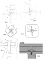
Figure 1 illustrates a series of views of a first embodiment of screwboss according to the invention; -
Figure 2 illustrates a series of views of a second embodiment of screwboss according to the invention; -
Figure 3 illustrates a plan view of a screwboss exemplifying various dimensions; -
Figure 4 illustrates a further plan view of a screwboss exemplifying various dimensions and directions of force; -
Figure 5 illustrates an overview of a third embodiment of screwboss; -
Figure 6 illustrates a plan view of a fourth embodiment of screwboss; -
Figure 7 illustrates a section view of a screw fastener in place with a screwboss for holding components of a product together; and -
Figure 8 illustrates frontal view of a product component featuring a screwboss of the invention. - The following description presents exemplary embodiments and, together with the drawings, serves to explain principles of the invention. However, the scope of the invention is not intended to be limited to the precise details of the embodiments or exact adherence with all features and/or method steps, since variations will be apparent to a skilled person and are deemed also to be covered by the description. Terms for components used herein should be given a broad interpretation that also encompasses equivalent functions and features. In some cases, several alternative terms (synonyms) for structural features have been provided but such terms are not intended to be exhaustive. Descriptive terms should also be given the broadest possible interpretation; e.g. the term "comprising" as used in this specification means "consisting at least in part of" such that interpreting each statement in this specification that includes the term "comprising", features other than that or those prefaced by the term may also be present. Related terms such as "comprise" and "comprises" are to be interpreted in the same manner. Directional terms such as "vertical", "horizontal", "up", "down", "sideways", "upper" and "lower" are used for convenience of explanation usually with reference to the orientation shown in illustrations and are not intended to be ultimately limiting if an equivalent function can be achieved with an alternative dimension and/or direction. Indeed, in the present case a term such as "horizontal" axis or "vertical" axis can be affected by the orientation imposed on the screwboss structure. Therefore, all directional terms are relative to each other.
- The description herein refers to embodiments with particular combinations of steps or features, however, it is envisaged that further combinations and cross-combinations of compatible steps or features between embodiments will be possible. Indeed, isolated features may function independently as an invention from other features and not necessarily require implementation as a complete combination.
- It will be understood that the illustrated embodiments show applications only for the purposes of explanation. In practice, the invention may be applied to many different configurations, where the embodiment is straightforward for those skilled in the art to implement.
-
Figure 1 outlines a series of views from various perspectives of ascrewboss 10 according to the invention.Screwboss 10 is generally comprised of a base 11 (which will in practice be part of a larger component element than that illustrated), an upstandingmain body 12 and a plurality ofribs 13. - In the illustrated form,
main body 12 is generally cylindrical in shape, although it may have other elongate forms, and features acentral opening 14 for receiving a screw fastener. In the illustrated example, the opening has a bevelled edge or annular inset, but otherwise has smooth walls down to a specified depth (e.g. seen inFigure 7 example). In principle the opening may be all the way throughbody 12 andbase 11, but is more likely a blind bore that at least leaves an open space beyond the distal end of a screw. - As best seen in the plan views of
Figures 1 to 4 , eachrib 13 extends away from a side wall ofbody 12 in a position that is parallel but offset to a radial line (R) taken from a central axis (X) of the opening/body. In this way, ribs extending from opposite sides of thebody 12 are not aligned and appear offset from one another. Yet, in the illustrated form with four ribs, the offset between adjacent ribs is still ninety degress as it would be for a regular cross configuration, as shown byFigure 4 . Ribs are shown with even spacing therebetween. - With reference to
Figures 3 and 4 , a desirable position of a rib according to the invention can be described in several ways. Firstly, a central plane P of arib 13 is shown as parallel to and offset from a radial line R, e.g. by more than half a thickness ofrib 13. Secondly, central plane P ofrib 13 is substantially tangential to a wall of opening 14 where, in use, a screw fastener would contact theboss body 12 and apply force thereto, e.g. in a clockwise direction assuming a common right hand screw thread. A directional force line F is shown inFigure 4 , resulting from a torsion force T caused by rotation of a screw fastener. Thirdly, an upstanding leading edge of an outside face of the rib, where it is connected to theside wall 12, begins approximately 40-70 degrees from the centre axis X of the hole. In all explanations, the position of therib 13 optimally provides support for resisting the torque force F applied by a turning screw during assembly and for a final torque applied to hold a component in place. - In general, it is apparent that
rib 13 is offset to one side of radial line R and not overlapping therewith. Alternatively or in addition, at the point whererib 13 is connected withbody 12, it extends from and overlaps with a tangent ofopening 14. Any part across the thickness of arib 13 may coincide with a tangential line from the hole/opening 14. According toFigure 4 , the centre plane P coincides with tangential line G. - The embodiment of
Figure 1 features fourribs 13 in the form of right angle triangular wedges, where the right angle corner is located at the join betweenbase 11 and upstandingmain body 12. The thickness is uniform, although alternative configurations are possible. -
Figure 2 illustrates an alternative embodiment ofscrew boss 10 where arib 13 is configured to taper with a draft angle outwardly from themain body 12, towardbase 11 where the rib is thickest. Indeed, in someembodiments body 12 may be independently tapered outwardly from the openingend 14 toward thebase 11. A draft of the type illustrated may assist with removal from an injection moulding tool, without significantly affecting its strength for accommodating torsion forces. As shown in the plan view ofFigure 2 , the positional arrangement ofribs 13 is otherwise analogous to that ofFigures 1 ,3 and 4 . -
Figure 5 illustrates a variation of the embodiment ofFigure 1 , where the effective upstanding height ofbody 12 is reduced. However, the function and position ofribs 13 remains the same. Any embodiment of the screwboss may have a height tailored to the length of screw needed for securing a component or to provide clearance or surface features on a component. -
Figure 6 illustrates a variation where substantive external surfaces of therib 13 are at positions approximately in line with a tangent line G from the opening and a radial line R from the centre axis X respectively. As before,rib 13 is generally offset from and parallel with the radial line R, but now with a thickness that is approximately equal to the radius of the opening 14 (i.e. half the diameter). This may exemplify an optimum position for a rib which uses less material but is best positioned for absorbing torque forces from a screw. It is noteworthy that, for all embodiments, a rib begins to extend from a position in line with (i.e. with any part of its thickness overlapping or at least an external surface in line with) a tangent to the opening, but an end of the rib distal from its connection to the main body may deviate from a straight line. A rib could be curved so long as it begins at a tangential position. -
Figure 7 illustrates a cross section view of an assembled product/component where a (e.g. self-tapping) screw fastener, having a threadedshaft 15 andhead 16, has been driven into theblind hole 14 of aboss body 12.Head 16 is generally rotated into engagement by a tool at a predetermined torque force, whereshaft 15 passes through aligned openings of one ormore component flanges screw boss 12 so as to distance electrical components on its surface from undesirable contact with a base (not shown) of the boss or acover component 18. - While not easily visible in
Figure 7 , outwardly extending ribs of the invention are arranged to accommodate the torque force asshaft 15 engages and drives intohole 14 and at conclusion of the screw cycle wherehead 16 contacts the components (17, 18) being secured. -
Figure 8 illustrates a plan view ofbase component 11 incorporating aboss 12 andrib structure 13 as described above.Ribs 13 may be incorporated with other strengthening ribs of thebase 11. In a case whereboss 12 is located in the corner of a component, upstanding side walls extending frombase 11 may provide a supporting function with a variation in size and/or number of supporting ribs according to the invention. - In consideration of the above, the improved rib structure is configured for mitigating forces applied during driving of a screw into a boss. Cycle time during the screwing process may be reduced. Assuming a similar amount of materials used in constructing the
boss 12, heat generation during screwing is expected to remain the same, or a bit higher due to faster screwing. - By way of summary, the invention is generally embodied by a screwboss comprised of a base and an upstanding main body having an opening at one end thereof. A series of ribs are spaced apart about the main body, each at a position offset from a normal radial position, i.e. generally coinciding with (toward, at or beyond) an imaginary tangent line extending from an edge of the opening. In this way, torque forces applied by a fastener driving into the opening are optimally absorbed by the rib position, such that a quicker cycle time for screwing a component in place can be achieved.
Claims (13)
- A screwboss (10) comprised of:a base (11);a main body (12);an opening (14) into an end of the main body (12), distal from the base (11), for fixing a threaded fastener (15) thereinto; andat least one rib (13), adjoining the base (11) and main body (12), to support the main body (12) in an upstanding position;wherein the at least one rib (13) extends from the main body (12) at a position offset from a radial line (R) from a centre axis (X) of the opening and toward a tangent (G) from the opening (14).
- The screwboss of claim 1, wherein the tangent line (G) coincides within a thickness of the at least one rib (13) .
- The screwboss of claim 1, wherein the at least one rib (13) has a first external surface in line with the radial line (R) and a second surface in line with the tangent line (G).
- The screwboss of any preceding claim, wherein the at least one rib (13) is tapered inwardly in a longitudinal direction from the base (11) toward the main body (12).
- The screwboss of any preceding claim, wherein the at least one rib (13), extending outwardly from the main body (12), has a draft angle.
- The screwboss of any preceding claim, wherein the at least one rib (13) comprises a plurality of ribs (13), each at a position in line with a tangent line (G) from the opening (14).
- The screwboss of claim 3, wherein each rib (13) of the plurality of ribs radiates at an even spacings about the main body (12).
- The screwboss of claim 3, configured for a right hand screw threaded fastener, wherein the at least one rib (13) is offset in a counter-clockwise direction from the radial line (R).
- The screwboss of claim 3 or 8, wherein the at least one rib (13) is offset far enough so as not to overlap with the radial line (R).
- A component incorporating a screwboss according to any preceding claim.
- The component of claim 10, wherein the component is configured for use in assembly of a vehicle.
- A method for mounting a first component part to a base component part, including:forming a screwboss, according to any preceding claim 1 to 9, into a surface of the base component part;aligning an opening of the first component part with the opening into the main body;optionally aligning an opening of a second or further component part with the opening into the main body;inserting a fastener through the aligned openings and turning same, in a direction counter to an offset in the at least one rib, to engage and be driven into the opening into the main body.
- The method of claim 12, wherein the base component part is part of a vehicle.
Priority Applications (3)
| Application Number | Priority Date | Filing Date | Title |
|---|---|---|---|
| EP22207891.7A EP4372237B1 (en) | 2022-11-16 | 2022-11-16 | Screw boss |
| CN202311425970.1A CN118049427A (en) | 2022-11-16 | 2023-10-30 | Screw boss |
| US18/510,080 US12359689B2 (en) | 2022-11-16 | 2023-11-15 | Ribbed screwboss |
Applications Claiming Priority (1)
| Application Number | Priority Date | Filing Date | Title |
|---|---|---|---|
| EP22207891.7A EP4372237B1 (en) | 2022-11-16 | 2022-11-16 | Screw boss |
Publications (2)
| Publication Number | Publication Date |
|---|---|
| EP4372237A1 true EP4372237A1 (en) | 2024-05-22 |
| EP4372237B1 EP4372237B1 (en) | 2025-08-13 |
Family
ID=84358491
Family Applications (1)
| Application Number | Title | Priority Date | Filing Date |
|---|---|---|---|
| EP22207891.7A Active EP4372237B1 (en) | 2022-11-16 | 2022-11-16 | Screw boss |
Country Status (3)
| Country | Link |
|---|---|
| US (1) | US12359689B2 (en) |
| EP (1) | EP4372237B1 (en) |
| CN (1) | CN118049427A (en) |
Citations (2)
| Publication number | Priority date | Publication date | Assignee | Title |
|---|---|---|---|---|
| JP4437132B2 (en) * | 2006-12-22 | 2010-03-24 | Necディスプレイソリューションズ株式会社 | Boss with screw hole |
| CN205025880U (en) * | 2015-09-29 | 2016-02-10 | 北汽福田汽车股份有限公司 | Erection column fixed structure |
Family Cites Families (9)
| Publication number | Priority date | Publication date | Assignee | Title |
|---|---|---|---|---|
| US3722565A (en) * | 1971-08-02 | 1973-03-27 | Miller R & Co Inc | Barbed t-nut |
| DE102009032945A1 (en) | 2009-07-14 | 2011-01-20 | Audi Ag | Threaded plate with stiffening ribs |
| CN103470602B (en) * | 2012-06-07 | 2015-06-03 | 纬创资通股份有限公司 | stud |
| US20150114544A1 (en) * | 2013-10-31 | 2015-04-30 | Caterpillar Inc. | Mounting structure and method of attaching mounting structure to surface |
| JP2016098979A (en) | 2014-11-26 | 2016-05-30 | ブラザー工業株式会社 | Self tap hub |
| DE102017104384B4 (en) | 2017-03-02 | 2024-01-25 | Lisa Dräxlmaier GmbH | COMPONENT WITH SCREW DOME AND METHOD FOR CONNECTING A COMPONENT |
| US10378569B2 (en) * | 2017-10-25 | 2019-08-13 | Caterpillar Inc. | Adhesive based mounting structure |
| US11078948B2 (en) | 2019-02-18 | 2021-08-03 | Ford Global Technologies, Llc | Fastener boss and motor vehicle component incorporating that fastener boss |
| JP2023043083A (en) * | 2021-09-15 | 2023-03-28 | 三菱重工業株式会社 | Fastener, fastening structure, and method for designing fastener |
-
2022
- 2022-11-16 EP EP22207891.7A patent/EP4372237B1/en active Active
-
2023
- 2023-10-30 CN CN202311425970.1A patent/CN118049427A/en active Pending
- 2023-11-15 US US18/510,080 patent/US12359689B2/en active Active
Patent Citations (2)
| Publication number | Priority date | Publication date | Assignee | Title |
|---|---|---|---|---|
| JP4437132B2 (en) * | 2006-12-22 | 2010-03-24 | Necディスプレイソリューションズ株式会社 | Boss with screw hole |
| CN205025880U (en) * | 2015-09-29 | 2016-02-10 | 北汽福田汽车股份有限公司 | Erection column fixed structure |
Also Published As
| Publication number | Publication date |
|---|---|
| US12359689B2 (en) | 2025-07-15 |
| US20240159263A1 (en) | 2024-05-16 |
| CN118049427A (en) | 2024-05-17 |
| EP4372237B1 (en) | 2025-08-13 |
Similar Documents
| Publication | Publication Date | Title |
|---|---|---|
| KR910009398B1 (en) | Cutter head for cutters | |
| EP2162625B1 (en) | Apparatus and methods for securing a fastener | |
| EP3002145A1 (en) | Vehicle grill shutter, vehicle flap member, and actuator | |
| CN109488570B (en) | Cylinder head assembly and compressor | |
| BR102017018480B1 (en) | ROTARY ELECTRIC ROTOR AND METHOD FOR MANUFACTURING A ROTARY ELECTRIC ROTOR | |
| EP3930089B1 (en) | Output electrode base, battery module, and electric vehicle | |
| EP4133188B1 (en) | Nut connection mechanism | |
| EP4372237B1 (en) | Screw boss | |
| US20260077389A1 (en) | Sorting module and sorting device | |
| CN216111377U (en) | Fan lamp | |
| KR20060042213A (en) | Ball screw and how to assemble it | |
| US12092144B2 (en) | Fastener, fastening structure, and method of designing fastener | |
| JP4437132B2 (en) | Boss with screw hole | |
| CN109488571B (en) | Cylinder head assembly and compressor | |
| US20070186709A1 (en) | Rotation drive | |
| CA1126061A (en) | Fastener and drive system | |
| CN223908577U (en) | A drywall nail with a keel structure | |
| JP7405944B2 (en) | connection structure | |
| EP2113421B1 (en) | Anchor for vehicle roof racks | |
| CN216488430U (en) | Cavity filter | |
| CN223754456U (en) | A fixed component and a vehicle | |
| KR101072781B1 (en) | Motor rotor | |
| CN118899600B (en) | Cover plate assembly and cylindrical lithium battery | |
| KR20220042196A (en) | motor and washing machine | |
| US20250320885A1 (en) | Threaded securement of enclosure components |
Legal Events
| Date | Code | Title | Description |
|---|---|---|---|
| PUAI | Public reference made under article 153(3) epc to a published international application that has entered the european phase |
Free format text: ORIGINAL CODE: 0009012 |
|
| STAA | Information on the status of an ep patent application or granted ep patent |
Free format text: STATUS: THE APPLICATION HAS BEEN PUBLISHED |
|
| AK | Designated contracting states |
Kind code of ref document: A1 Designated state(s): AL AT BE BG CH CY CZ DE DK EE ES FI FR GB GR HR HU IE IS IT LI LT LU LV MC ME MK MT NL NO PL PT RO RS SE SI SK SM TR |
|
| STAA | Information on the status of an ep patent application or granted ep patent |
Free format text: STATUS: REQUEST FOR EXAMINATION WAS MADE |
|
| 17P | Request for examination filed |
Effective date: 20240628 |
|
| RBV | Designated contracting states (corrected) |
Designated state(s): AL AT BE BG CH CY CZ DE DK EE ES FI FR GB GR HR HU IE IS IT LI LT LU LV MC ME MK MT NL NO PL PT RO RS SE SI SK SM TR |
|
| RAP3 | Party data changed (applicant data changed or rights of an application transferred) |
Owner name: APTIV TECHNOLOGIES AG |
|
| GRAP | Despatch of communication of intention to grant a patent |
Free format text: ORIGINAL CODE: EPIDOSNIGR1 |
|
| STAA | Information on the status of an ep patent application or granted ep patent |
Free format text: STATUS: GRANT OF PATENT IS INTENDED |
|
| RIC1 | Information provided on ipc code assigned before grant |
Ipc: F16B 25/00 20060101ALN20250321BHEP Ipc: F16B 5/02 20060101AFI20250321BHEP |
|
| INTG | Intention to grant announced |
Effective date: 20250404 |
|
| RIN1 | Information on inventor provided before grant (corrected) |
Inventor name: KAMINSKI, BARTLOMIEJ Inventor name: SUROWIAK, KACPER |
|
| GRAS | Grant fee paid |
Free format text: ORIGINAL CODE: EPIDOSNIGR3 |
|
| GRAA | (expected) grant |
Free format text: ORIGINAL CODE: 0009210 |
|
| STAA | Information on the status of an ep patent application or granted ep patent |
Free format text: STATUS: THE PATENT HAS BEEN GRANTED |
|
| AK | Designated contracting states |
Kind code of ref document: B1 Designated state(s): AL AT BE BG CH CY CZ DE DK EE ES FI FR GB GR HR HU IE IS IT LI LT LU LV MC ME MK MT NL NO PL PT RO RS SE SI SK SM TR |
|
| REG | Reference to a national code |
Ref country code: GB Ref legal event code: FG4D |
|
| REG | Reference to a national code |
Ref country code: CH Ref legal event code: EP |
|
| REG | Reference to a national code |
Ref country code: DE Ref legal event code: R096 Ref document number: 602022019325 Country of ref document: DE |
|
| P01 | Opt-out of the competence of the unified patent court (upc) registered |
Free format text: CASE NUMBER: UPC_APP_1315_4372237/2025 Effective date: 20250729 |
|
| REG | Reference to a national code |
Ref country code: IE Ref legal event code: FG4D |
|
| REG | Reference to a national code |
Ref country code: NL Ref legal event code: MP Effective date: 20250813 |
|
| PG25 | Lapsed in a contracting state [announced via postgrant information from national office to epo] |
Ref country code: IS Free format text: LAPSE BECAUSE OF FAILURE TO SUBMIT A TRANSLATION OF THE DESCRIPTION OR TO PAY THE FEE WITHIN THE PRESCRIBED TIME-LIMIT Effective date: 20251213 |
|
| PGFP | Annual fee paid to national office [announced via postgrant information from national office to epo] |
Ref country code: DE Payment date: 20251010 Year of fee payment: 4 |
|
| PG25 | Lapsed in a contracting state [announced via postgrant information from national office to epo] |
Ref country code: NO Free format text: LAPSE BECAUSE OF FAILURE TO SUBMIT A TRANSLATION OF THE DESCRIPTION OR TO PAY THE FEE WITHIN THE PRESCRIBED TIME-LIMIT Effective date: 20251113 |
|
| REG | Reference to a national code |
Ref country code: LT Ref legal event code: MG9D |
|
| PG25 | Lapsed in a contracting state [announced via postgrant information from national office to epo] |
Ref country code: PT Free format text: LAPSE BECAUSE OF FAILURE TO SUBMIT A TRANSLATION OF THE DESCRIPTION OR TO PAY THE FEE WITHIN THE PRESCRIBED TIME-LIMIT Effective date: 20251215 |
|
| PG25 | Lapsed in a contracting state [announced via postgrant information from national office to epo] |
Ref country code: FI Free format text: LAPSE BECAUSE OF FAILURE TO SUBMIT A TRANSLATION OF THE DESCRIPTION OR TO PAY THE FEE WITHIN THE PRESCRIBED TIME-LIMIT Effective date: 20250813 |
|
| PG25 | Lapsed in a contracting state [announced via postgrant information from national office to epo] |
Ref country code: HR Free format text: LAPSE BECAUSE OF FAILURE TO SUBMIT A TRANSLATION OF THE DESCRIPTION OR TO PAY THE FEE WITHIN THE PRESCRIBED TIME-LIMIT Effective date: 20250813 Ref country code: NL Free format text: LAPSE BECAUSE OF FAILURE TO SUBMIT A TRANSLATION OF THE DESCRIPTION OR TO PAY THE FEE WITHIN THE PRESCRIBED TIME-LIMIT Effective date: 20250813 |
|
| PGFP | Annual fee paid to national office [announced via postgrant information from national office to epo] |
Ref country code: FR Payment date: 20251112 Year of fee payment: 4 |
|
| PG25 | Lapsed in a contracting state [announced via postgrant information from national office to epo] |
Ref country code: GR Free format text: LAPSE BECAUSE OF FAILURE TO SUBMIT A TRANSLATION OF THE DESCRIPTION OR TO PAY THE FEE WITHIN THE PRESCRIBED TIME-LIMIT Effective date: 20251114 |
|
| PG25 | Lapsed in a contracting state [announced via postgrant information from national office to epo] |
Ref country code: SE Free format text: LAPSE BECAUSE OF FAILURE TO SUBMIT A TRANSLATION OF THE DESCRIPTION OR TO PAY THE FEE WITHIN THE PRESCRIBED TIME-LIMIT Effective date: 20250813 |
|
| PG25 | Lapsed in a contracting state [announced via postgrant information from national office to epo] |
Ref country code: LV Free format text: LAPSE BECAUSE OF FAILURE TO SUBMIT A TRANSLATION OF THE DESCRIPTION OR TO PAY THE FEE WITHIN THE PRESCRIBED TIME-LIMIT Effective date: 20250813 |
|
| PG25 | Lapsed in a contracting state [announced via postgrant information from national office to epo] |
Ref country code: BG Free format text: LAPSE BECAUSE OF FAILURE TO SUBMIT A TRANSLATION OF THE DESCRIPTION OR TO PAY THE FEE WITHIN THE PRESCRIBED TIME-LIMIT Effective date: 20250813 Ref country code: PL Free format text: LAPSE BECAUSE OF FAILURE TO SUBMIT A TRANSLATION OF THE DESCRIPTION OR TO PAY THE FEE WITHIN THE PRESCRIBED TIME-LIMIT Effective date: 20250813 |
|
| PG25 | Lapsed in a contracting state [announced via postgrant information from national office to epo] |
Ref country code: RS Free format text: LAPSE BECAUSE OF FAILURE TO SUBMIT A TRANSLATION OF THE DESCRIPTION OR TO PAY THE FEE WITHIN THE PRESCRIBED TIME-LIMIT Effective date: 20251113 |
|
| PG25 | Lapsed in a contracting state [announced via postgrant information from national office to epo] |
Ref country code: ES Free format text: LAPSE BECAUSE OF FAILURE TO SUBMIT A TRANSLATION OF THE DESCRIPTION OR TO PAY THE FEE WITHIN THE PRESCRIBED TIME-LIMIT Effective date: 20250813 |
|
| REG | Reference to a national code |
Ref country code: AT Ref legal event code: MK05 Ref document number: 1824895 Country of ref document: AT Kind code of ref document: T Effective date: 20250813 |
|
| PG25 | Lapsed in a contracting state [announced via postgrant information from national office to epo] |
Ref country code: RO Free format text: LAPSE BECAUSE OF FAILURE TO SUBMIT A TRANSLATION OF THE DESCRIPTION OR TO PAY THE FEE WITHIN THE PRESCRIBED TIME-LIMIT Effective date: 20250813 |
|
| PG25 | Lapsed in a contracting state [announced via postgrant information from national office to epo] |
Ref country code: SM Free format text: LAPSE BECAUSE OF FAILURE TO SUBMIT A TRANSLATION OF THE DESCRIPTION OR TO PAY THE FEE WITHIN THE PRESCRIBED TIME-LIMIT Effective date: 20250813 |
|
| PG25 | Lapsed in a contracting state [announced via postgrant information from national office to epo] |
Ref country code: DK Free format text: LAPSE BECAUSE OF FAILURE TO SUBMIT A TRANSLATION OF THE DESCRIPTION OR TO PAY THE FEE WITHIN THE PRESCRIBED TIME-LIMIT Effective date: 20250813 |
|
| PG25 | Lapsed in a contracting state [announced via postgrant information from national office to epo] |
Ref country code: AT Free format text: LAPSE BECAUSE OF FAILURE TO SUBMIT A TRANSLATION OF THE DESCRIPTION OR TO PAY THE FEE WITHIN THE PRESCRIBED TIME-LIMIT Effective date: 20250813 |
|
| PG25 | Lapsed in a contracting state [announced via postgrant information from national office to epo] |
Ref country code: IT Free format text: LAPSE BECAUSE OF FAILURE TO SUBMIT A TRANSLATION OF THE DESCRIPTION OR TO PAY THE FEE WITHIN THE PRESCRIBED TIME-LIMIT Effective date: 20250813 |
|
| PG25 | Lapsed in a contracting state [announced via postgrant information from national office to epo] |
Ref country code: CZ Free format text: LAPSE BECAUSE OF FAILURE TO SUBMIT A TRANSLATION OF THE DESCRIPTION OR TO PAY THE FEE WITHIN THE PRESCRIBED TIME-LIMIT Effective date: 20250813 |
|
| PG25 | Lapsed in a contracting state [announced via postgrant information from national office to epo] |
Ref country code: EE Free format text: LAPSE BECAUSE OF FAILURE TO SUBMIT A TRANSLATION OF THE DESCRIPTION OR TO PAY THE FEE WITHIN THE PRESCRIBED TIME-LIMIT Effective date: 20250813 Ref country code: SK Free format text: LAPSE BECAUSE OF FAILURE TO SUBMIT A TRANSLATION OF THE DESCRIPTION OR TO PAY THE FEE WITHIN THE PRESCRIBED TIME-LIMIT Effective date: 20250813 |