EP4371887A1 - Contrail detection, discrimination, and control - Google Patents
Contrail detection, discrimination, and control Download PDFInfo
- Publication number
- EP4371887A1 EP4371887A1 EP23211108.8A EP23211108A EP4371887A1 EP 4371887 A1 EP4371887 A1 EP 4371887A1 EP 23211108 A EP23211108 A EP 23211108A EP 4371887 A1 EP4371887 A1 EP 4371887A1
- Authority
- EP
- European Patent Office
- Prior art keywords
- sensor
- controller
- aircraft
- volume
- contrail
- Prior art date
- Legal status (The legal status is an assumption and is not a legal conclusion. Google has not performed a legal analysis and makes no representation as to the accuracy of the status listed.)
- Pending
Links
Images
Classifications
-
- F—MECHANICAL ENGINEERING; LIGHTING; HEATING; WEAPONS; BLASTING
- F02—COMBUSTION ENGINES; HOT-GAS OR COMBUSTION-PRODUCT ENGINE PLANTS
- F02C—GAS-TURBINE PLANTS; AIR INTAKES FOR JET-PROPULSION PLANTS; CONTROLLING FUEL SUPPLY IN AIR-BREATHING JET-PROPULSION PLANTS
- F02C9/00—Controlling gas-turbine plants; Controlling fuel supply in air- breathing jet-propulsion plants
- F02C9/26—Control of fuel supply
- F02C9/28—Regulating systems responsive to plant or ambient parameters, e.g. temperature, pressure, rotor speed
-
- B—PERFORMING OPERATIONS; TRANSPORTING
- B64—AIRCRAFT; AVIATION; COSMONAUTICS
- B64D—EQUIPMENT FOR FITTING IN OR TO AIRCRAFT; FLIGHT SUITS; PARACHUTES; ARRANGEMENT OR MOUNTING OF POWER PLANTS OR PROPULSION TRANSMISSIONS IN AIRCRAFT
- B64D45/00—Aircraft indicators or protectors not otherwise provided for
-
- G—PHYSICS
- G01—MEASURING; TESTING
- G01S—RADIO DIRECTION-FINDING; RADIO NAVIGATION; DETERMINING DISTANCE OR VELOCITY BY USE OF RADIO WAVES; LOCATING OR PRESENCE-DETECTING BY USE OF THE REFLECTION OR RERADIATION OF RADIO WAVES; ANALOGOUS ARRANGEMENTS USING OTHER WAVES
- G01S17/00—Systems using the reflection or reradiation of electromagnetic waves other than radio waves, e.g. lidar systems
- G01S17/88—Lidar systems specially adapted for specific applications
-
- G—PHYSICS
- G01—MEASURING; TESTING
- G01W—METEOROLOGY
- G01W1/00—Meteorology
- G01W1/08—Adaptations of balloons, missiles, or aircraft for meteorological purposes; Radiosondes
-
- G—PHYSICS
- G06—COMPUTING OR CALCULATING; COUNTING
- G06V—IMAGE OR VIDEO RECOGNITION OR UNDERSTANDING
- G06V20/00—Scenes; Scene-specific elements
- G06V20/50—Context or environment of the image
- G06V20/56—Context or environment of the image exterior to a vehicle by using sensors mounted on the vehicle
-
- G—PHYSICS
- G08—SIGNALLING
- G08G—TRAFFIC CONTROL SYSTEMS
- G08G5/00—Traffic control systems for aircraft
- G08G5/30—Flight plan management
- G08G5/34—Flight plan management for flight plan modification
-
- B—PERFORMING OPERATIONS; TRANSPORTING
- B64—AIRCRAFT; AVIATION; COSMONAUTICS
- B64G—COSMONAUTICS; VEHICLES OR EQUIPMENT THEREFOR
- B64G1/00—Cosmonautic vehicles
- B64G1/10—Artificial satellites; Systems of such satellites; Interplanetary vehicles
- B64G1/1021—Earth observation satellites
- B64G1/1042—Earth observation satellites specifically adapted for meteorology
Definitions
- the present disclosure relates to contrails formed by aircraft, and more particularly to detection, discrimination, and mitigation of contrails.
- a system includes a first sensor positioned to sense presence of a contrail in a first volume, wherein the first volume at least partially overlaps an expected volume of a contrail proximate an aircraft.
- a second sensor is positioned to sense a background reference in a second volume, where the second volume does not overlap the expected volume of a contrail proximate an aircraft.
- a controller is operatively connected to the first and second sensors. The controller includes machine readable instructions configured to cause the controller to utilize data input from both the first and second volumes to determine if a contrail is present from the aircraft.
- a third sensor can be positioned to sense presence of a contrail in a third volume, wherein the third volume at least partially overlaps the expected volume of a contrail at a position downstream in the contrail, and wherein the controller is operatively connected to the third sensor and includes machine readable instructions configured to cause the controller to predict persistence of a contrail, if present, based on comparison of data from the first and third volumes.
- the controller can include machine readable instructions configured to cause the controller to predict persistence of a contrail, if present, based on data from the second volume.
- the machine readable instructions can be configured to cause the controller to receive additional sensor data and comparing data from the first and second volumes in conjunction with the additional sensor data to predict persistence of a contrail if present, wherein the additional data includes at least one of ambient temperature, humidity, pressure, particulate count information, and presence of polyaromatic hydrocarbons, wherein the additional data comes from sensors onboard the aircraft or from an external source.
- the first sensor can include a first illuminator configured to illuminate the first volume and a first photodetector configured to receive a return from the first illuminator.
- the second sensor can include a second illuminator configured to illuminate the second volume and a second photodetector configured to receive a return from the second illuminator.
- the machine readable instructions can include instruction configured to convert time of flight data from the first and second sensors into data indicative of presence or lack of presence of particles.
- the first sensor can be an optical sensor, and the second sensor can be a non-optical sensor.
- the first sensor can be directed in an aft direction relative to the aircraft so that the first volume is aft of the aircraft.
- the second sensor can be directed forward relative to the aircraft, starboard relative to the aircraft, port relative to the aircraft, above the aircraft, below the aircraft; and/or between two contrail zones aft of the aircraft.
- a system includes a sensor configured to sense data indicative of atmospheric conditions in a volume of airspace.
- a controller is operatively connected to the sensor.
- the controller includes machine readable instructions configured to cause the controller to predict persistence of contrails on an intended route through the volume of airspace and to determine an improved route and/or propulsion operation to reduce contrail formation and persistence relative to the intended route.
- the machine readable instructions can be configured to output the improved route and/or propulsion operation to reroute a flight in progress.
- the controller can be onboard the flight in progress.
- the controller can be surface based, wherein the controller is operatively connected to communicate the improved route and/or propulsion operation to the flight in progress.
- the controller can be space-based and/or part of a satellite network.
- the controller can be based on a communication network of aircraft.
- the machine readable instructions can be configured to output the improved route and/or propulsion operation to plan one or more future flights.
- the machine readable instructions can be configured to determine the improved route and/or propulsion operation based at least in part on fuel efficiency.
- the machine readable instructions can be configured to alter at least one of aircraft flight parameter, map course and altitude course from the intended route to determine the improved route and/or propulsion operation.
- the sensor can include at least one sensor of a type selected from the group consisting of: an optical sensor system onboard an aircraft; a network of optical sensor systems onboard an aircraft; surface weather sensor systems; a network of surface weather sensor systems; and an orbital optical sensor system.
- the machine readable instructions can include instructions configured to cause the controller to reroute subsequent flights after a sensor onboard a prior flight following the intended route detects formation of persistent contrails on the prior flight so the subsequent flights follow the improved route and/or propulsion operation.
- the machine readable instructions can include instructions configured to cause the controller to predict formation of persistent contrails on the intended route and to reroute all flights from the intended route to the improved route and/or propulsion operation for a period of time as long as conditions for the formation of persistent contrails on the intended route persist.
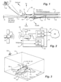
- Fig. 1 a partial view of an embodiment of a system in accordance with the disclosure is shown in Fig. 1 and is designated generally by reference character 100.
- Other embodiments of systems in accordance with the disclosure, or aspects thereof, are provided in Figs. 2-3 , as will be described.
- the systems and methods described herein can be used to detect contrails, discriminate between fleeting and persistent contrails, and control to reduce or avoid formation of persistent contrails.
- the system 100 includes a first sensor 102 positioned to sense presence of a contrail in a first volume 104, e.g. in the interrogation cone of the sensor 102.
- the first volume at least partially overlaps an expected volume of a contrail 106 proximate to and aft of an aircraft 10, i.e. the volume where a contrail 106 would appear if conditions are conducive to contrail formation.
- a second sensor 108 is positioned to sense a background reference in a second volume 110, i.e. in the interrogation cone of the sensor 108. In order to better determine a background reference, e.g.
- the sensor 108 is directed forward from the aircraft 10 so the second volume 110 does not overlap the expected volume of a contrail 106 proximate an aircraft 10.
- Other suitable directions, indicated by the directional arrows in Fig. 1 for the sensor 108 to be directed include upwards from the aircraft 10, downwards from the aircraft 10, outward in either lateral direction (port or starboard) from the aircraft 10, or backwards from the aircraft 10 in a volume where contrails are not expected to form, e.g. from sensor 114 at the top of the tail of the aircraft with its interrogation cone 116 directed aft but not overlapping with the expected contrail volumes of any engine of the aircraft 10.
- Each sensor can have a conical interrogation volume, defined by a conical angle 0, which is labeled on volume 110.
- a controller 118 is operatively connected to the first and second sensors 102, 108.
- the controller 118 includes machine readable instructions 120 (indicated in Fig. 3 ) configured to cause the controller 118 to utilize data input from both the first and second volumes 104, 106 to determine if a contrail is present from the aircraft.
- the controller 118 can include logic configured to compare input from the sensors 102, 108. If data input to the controller 118 from both sensors 102, 108 indicate presence of water and/or ice particles, the controller 118 can include logic to conclude the aircraft 10 is not forming a contrail 106.
- the controller 118 can include logic to conclude aircraft 10 is not forming a contrail 106. But if the data input from the first sensor 102 indicates presence of water and/or ice particles, and the data input from the second sensor 108 indicates lack of water and/or ice particles, the controller 118 can include logic to conclude the aircraft 10 is forming a contrail 106.
- a third sensor 122 can be positioned to sense presence of a contrail in a third volume 124, i.e. in the interrogation cone of the sensor 122.
- the third volume 124 at least partially overlaps the expected volume of a contrail 106 at a position 126 downstream in the contrail 106 relative to the aircraft 10.
- One or more additional sensors like sensor 122 can optionally be used to interrogate different downstream positions of the contrail 106 (if a contrail 106 is present).
- the third sensor 122 and/or additional sensors can be optical sensors, or any suitable non-optical type sensors capable of collecting relevant environmental data.
- the controller 118 is operatively connected to the third sensor(s) 122 and includes machine readable instructions 120 configured to cause the controller 118 to predict persistence of a contrail 106, if present, based on comparison of data from the first and third volumes.
- the controller includes machine readable instructions 120 configured to cause the controller to base its prediction of persistence of a contrail, if present, on data from the second volume 110 as well. This can allow correlation of factors such as presence of cirrus clouds, non-contrail water/ice in background, and the like.
- the machine readable instructions 120 are configured to cause the controller 118 to receive additional sensor data, e.g. from onboard environmental sensors 128 configured to sense altitude, at least one of ambient temperature, humidity, pressure, particulate count information (which can be indicative of likelihood of nucleating contrails), and/or presence of polyaromatic hydrocarbons (which can be a factor in calculating persistence of contrails) outside of the aircraft 10, and/or weather data from an external satellite or ground/surface source 130 received wirelessly as indicted by the antennae 132 in Fig. 2 .
- the machine readable instructions 120 can cause the controller 118 to compare data from the first and second volumes 104, 110 in conjunction with the additional sensor data to predict persistence of a contrail 106 if present.
- the first sensor 102 includes a first LIDAR illuminator 134 configured to illuminate the first volume 104 and a first photodetector 135 configured to receive a return from the first illuminator 134, as indicated by the large arrows into and out of the sensor 102 in Fig. 2 .
- the second sensor 108 includes a second LIDAR illuminator 138 configured to illuminate the second volume 110 and a second photodetector 140 configured to receive a return from the second illuminator 138, as indicated by the large arrows into and out of the sensor 108 in Fig. 2 .
- the machine readable instructions 120 include instructions configured to cause the controller 118 to convert time of flight data from the first and second sensors 102, 108 into data indicative of presence or lack of presence of water and/or ice particles.
- the aircraft 10 and system 100 can use the sensors 102, 108, 128, or from the external source 130, to sense data indicative of atmospheric conditions in a volume 142 of airspace.
- the controller 118 includes machine readable instructions 120 configured to cause the controller 118 to predict persistence of contrails 106 on an intended route 144 through the volume 142 of airspace and to determine an improved route 146 to reduce contrail formation and persistence relative to the intended route 144.
- Each route 144, 146 includes a map path 148, and altitude path 150, represented by the vertical bars between each route 144, 146 and the map path 148.
- the improved route 146 can have a different map path 148 and/or a different altitude path 150 from the intended route 144.
- an improved operation of the aircrafts propulsion system can be determined and followed, e.g. if changing the fuel to air ratio or other engine/propulsion parameters can be adjusted even temporarily to reduce particulate formation and mitigate contrail formation with or without a change in the route.
- the machine readable instructions 120 are configured to output the improved route 146 to reroute a flight in progress, i.e. to reroute the aircraft 10 in Fig. 3 off from its position on the intended route 144 to the improved route 146.
- the controller 118 can be onboard the aircraft 10 during the flight in progress. It is also contemplated that the controller 118 can be surface based, e.g. in the station 130a of Fig. 3 , or air or space borne, as in the satellite 130b in Fig. 3 or a space-based network of satellites, and/or in a network of aircraft such as drones or the flights as shown in Fig. 3 , wherein the controller 118 is operatively connected to communicate the improved route to the flight in progress, and to receive background, contrail, and/or contrail persistence data from the aircraft 10 using one or more of the sensors described above onboard the aircraft 10.
- the machine readable instructions 120 can be configured to output the improved route 146 to plan one or more future flights 153, which might otherwise be planned to follow the intended route 144 or a similar route in or through the airspace volume 142.
- the machine readable instructions can be configured to determine the improved route based at least in part on fuel efficiency for the aircraft 10 and/or subsequent aircraft 153.
- the sensors for the system 100 can include one or more of an optical sensor systems onboard an aircraft, e.g. sensors 102, 108, 114, 128 described above with reference to Figs. 1 and 2 ; a network of optical sensor systems onboard an aircraft; surface weather sensor systems, e.g. from station 130a; a network of surface weather sensor systems; and/or an airborne or orbital optical sensor system such as satellite 130b.
- the machine readable instructions 120 can include instructions configured to cause the controller 118 to reroute subsequent flights 153 after a sensor onboard a prior flight, e.g. the aircraft 10 in Fig. 3 , following the intended route 144 detects formation of persistent contrails 106 on the prior flight so the subsequent flights 153 can follow the improved route 146 to reduce or eliminate persistent contrails 106.
- the machine readable instructions 120 can include instructions configured to cause the controller 118 to predict formation of persistent contrails on the intended route 144 and to reroute all flights 10, 153 from the intended route 144 to the improved route 146 for a period of time as long as conditions for the formation of persistent contrails 106 on the intended route 144 persist.
Landscapes
- Engineering & Computer Science (AREA)
- Physics & Mathematics (AREA)
- General Physics & Mathematics (AREA)
- Aviation & Aerospace Engineering (AREA)
- Chemical & Material Sciences (AREA)
- Combustion & Propulsion (AREA)
- Environmental & Geological Engineering (AREA)
- General Engineering & Computer Science (AREA)
- Theoretical Computer Science (AREA)
- Multimedia (AREA)
- Mechanical Engineering (AREA)
- Electromagnetism (AREA)
- Remote Sensing (AREA)
- Radar, Positioning & Navigation (AREA)
- Computer Networks & Wireless Communication (AREA)
- Life Sciences & Earth Sciences (AREA)
- Atmospheric Sciences (AREA)
- Biodiversity & Conservation Biology (AREA)
- Ecology (AREA)
- Environmental Sciences (AREA)
- Traffic Control Systems (AREA)
Abstract
Description
- The present disclosure relates to contrails formed by aircraft, and more particularly to detection, discrimination, and mitigation of contrails.
- Contrails from jet exhaust impact climate change via the formation of ice crystals in the atmosphere. Ice crystals from persistent contrails impact climate change via radiative forcing, which may have a net cooling or heating effect. NASA has recognized that for a given aircraft, contrail formation has a more immediate impact on climate change than carbon dioxide emissions. Monitoring and understanding contrails, along with control of contrails where possible, are important needs for reducing global warming.
- The conventional techniques have been considered satisfactory for their intended purpose. However, there is an ever present need for improved systems and methods for detecting, discriminating, and controlling contrails from aircraft. This disclosure provides a solution for this need.
- A system includes a first sensor positioned to sense presence of a contrail in a first volume, wherein the first volume at least partially overlaps an expected volume of a contrail proximate an aircraft. A second sensor is positioned to sense a background reference in a second volume, where the second volume does not overlap the expected volume of a contrail proximate an aircraft. A controller is operatively connected to the first and second sensors. The controller includes machine readable instructions configured to cause the controller to utilize data input from both the first and second volumes to determine if a contrail is present from the aircraft.
- A third sensor can be positioned to sense presence of a contrail in a third volume, wherein the third volume at least partially overlaps the expected volume of a contrail at a position downstream in the contrail, and wherein the controller is operatively connected to the third sensor and includes machine readable instructions configured to cause the controller to predict persistence of a contrail, if present, based on comparison of data from the first and third volumes.
- The controller can include machine readable instructions configured to cause the controller to predict persistence of a contrail, if present, based on data from the second volume. The machine readable instructions can be configured to cause the controller to receive additional sensor data and comparing data from the first and second volumes in conjunction with the additional sensor data to predict persistence of a contrail if present, wherein the additional data includes at least one of ambient temperature, humidity, pressure, particulate count information, and presence of polyaromatic hydrocarbons, wherein the additional data comes from sensors onboard the aircraft or from an external source.
- The first sensor can include a first illuminator configured to illuminate the first volume and a first photodetector configured to receive a return from the first illuminator. The second sensor can include a second illuminator configured to illuminate the second volume and a second photodetector configured to receive a return from the second illuminator. The machine readable instructions can include instruction configured to convert time of flight data from the first and second sensors into data indicative of presence or lack of presence of particles. The first sensor can be an optical sensor, and the second sensor can be a non-optical sensor.
- The first sensor can be directed in an aft direction relative to the aircraft so that the first volume is aft of the aircraft. The second sensor can be directed forward relative to the aircraft, starboard relative to the aircraft, port relative to the aircraft, above the aircraft, below the aircraft; and/or between two contrail zones aft of the aircraft.
- A system includes a sensor configured to sense data indicative of atmospheric conditions in a volume of airspace. A controller is operatively connected to the sensor. The controller includes machine readable instructions configured to cause the controller to predict persistence of contrails on an intended route through the volume of airspace and to determine an improved route and/or propulsion operation to reduce contrail formation and persistence relative to the intended route.
- The machine readable instructions can be configured to output the improved route and/or propulsion operation to reroute a flight in progress. The controller can be onboard the flight in progress. The controller can be surface based, wherein the controller is operatively connected to communicate the improved route and/or propulsion operation to the flight in progress. The controller can be space-based and/or part of a satellite network. The controller can be based on a communication network of aircraft.
- The machine readable instructions can be configured to output the improved route and/or propulsion operation to plan one or more future flights. The machine readable instructions can be configured to determine the improved route and/or propulsion operation based at least in part on fuel efficiency. The machine readable instructions can be configured to alter at least one of aircraft flight parameter, map course and altitude course from the intended route to determine the improved route and/or propulsion operation. The sensor can include at least one sensor of a type selected from the group consisting of: an optical sensor system onboard an aircraft; a network of optical sensor systems onboard an aircraft; surface weather sensor systems; a network of surface weather sensor systems; and an orbital optical sensor system.
- The machine readable instructions can include instructions configured to cause the controller to reroute subsequent flights after a sensor onboard a prior flight following the intended route detects formation of persistent contrails on the prior flight so the subsequent flights follow the improved route and/or propulsion operation. The machine readable instructions can include instructions configured to cause the controller to predict formation of persistent contrails on the intended route and to reroute all flights from the intended route to the improved route and/or propulsion operation for a period of time as long as conditions for the formation of persistent contrails on the intended route persist.
- These and other features of the systems and methods of the subject disclosure will become more readily apparent to those skilled in the art from the following detailed description of the preferred embodiments taken in conjunction with the drawings.
- So that those skilled in the art to which the subject disclosure appertains will readily understand how to make and use the devices and methods of the subject disclosure without undue experimentation, preferred embodiments thereof will be described in detail herein below with reference to certain figures, wherein:
-
Fig. 1 is a schematic perspective view of an embodiment of a system constructed in accordance with the present disclosure, showing an aircraft with contrail volumes and sensor volumes for detecting background and contrail data; -
Fig. 2 is a schematic view of the system ofFig. 1 , showing the controller and some of the sensors connected to the controller; and -
Fig. 3 is a schematic view of an airspace with a system as inFig. 1 , showing re-routing and route planning based on predicted contrail persistence. - Reference will now be made to the drawings wherein like reference numerals identify similar structural features or aspects of the subject disclosure. For purposes of explanation and illustration, and not limitation, a partial view of an embodiment of a system in accordance with the disclosure is shown in
Fig. 1 and is designated generally byreference character 100. Other embodiments of systems in accordance with the disclosure, or aspects thereof, are provided inFigs. 2-3 , as will be described. The systems and methods described herein can be used to detect contrails, discriminate between fleeting and persistent contrails, and control to reduce or avoid formation of persistent contrails. - The
system 100 includes afirst sensor 102 positioned to sense presence of a contrail in afirst volume 104, e.g. in the interrogation cone of thesensor 102. The first volume at least partially overlaps an expected volume of acontrail 106 proximate to and aft of anaircraft 10, i.e. the volume where acontrail 106 would appear if conditions are conducive to contrail formation. Asecond sensor 108 is positioned to sense a background reference in asecond volume 110, i.e. in the interrogation cone of thesensor 108. In order to better determine a background reference, e.g. to determine whether theaircraft 10 is in a cloud that thefirst sensor 102 could detect instead of a contrail, thesensor 108 is directed forward from theaircraft 10 so thesecond volume 110 does not overlap the expected volume of acontrail 106 proximate anaircraft 10. Other suitable directions, indicated by the directional arrows inFig. 1 , for thesensor 108 to be directed include upwards from theaircraft 10, downwards from theaircraft 10, outward in either lateral direction (port or starboard) from theaircraft 10, or backwards from theaircraft 10 in a volume where contrails are not expected to form, e.g. fromsensor 114 at the top of the tail of the aircraft with itsinterrogation cone 116 directed aft but not overlapping with the expected contrail volumes of any engine of theaircraft 10. This could includesensor 114 facing aft between twocontrails 106, or aft below thecontrails 106. Any oblique combination of these directions that does not overlap with the expected contrail volume of the engines of theaircraft 10 can also be used for background data. Each sensor can have a conical interrogation volume, defined by a conical angle 0, which is labeled onvolume 110. - A
controller 118 is operatively connected to the first andsecond sensors controller 118 includes machine readable instructions 120 (indicated inFig. 3 ) configured to cause thecontroller 118 to utilize data input from both the first andsecond volumes controller 118 can include logic configured to compare input from thesensors controller 118 from bothsensors controller 118 can include logic to conclude theaircraft 10 is not forming acontrail 106. Similarly, if the data input from bothsensors controller 118 can include logic to concludeaircraft 10 is not forming acontrail 106. But if the data input from thefirst sensor 102 indicates presence of water and/or ice particles, and the data input from thesecond sensor 108 indicates lack of water and/or ice particles, thecontroller 118 can include logic to conclude theaircraft 10 is forming acontrail 106. - With continued reference to
Fig. 1 , if a contrail is present, it is important to know whether the contrail will persist or will disappear quickly. There is little if any global warming impact from a contrail that disappears quickly-the contrails that have a substantial impact are those that persist long after the aircraft has passed. Athird sensor 122 can be positioned to sense presence of a contrail in athird volume 124, i.e. in the interrogation cone of thesensor 122. Thethird volume 124 at least partially overlaps the expected volume of acontrail 106 at aposition 126 downstream in thecontrail 106 relative to theaircraft 10. One or more additional sensors likesensor 122 can optionally be used to interrogate different downstream positions of the contrail 106 (if acontrail 106 is present). Thethird sensor 122 and/or additional sensors can be optical sensors, or any suitable non-optical type sensors capable of collecting relevant environmental data. Thecontroller 118 is operatively connected to the third sensor(s) 122 and includes machinereadable instructions 120 configured to cause thecontroller 118 to predict persistence of acontrail 106, if present, based on comparison of data from the first and third volumes. The controller includes machinereadable instructions 120 configured to cause the controller to base its prediction of persistence of a contrail, if present, on data from thesecond volume 110 as well. This can allow correlation of factors such as presence of cirrus clouds, non-contrail water/ice in background, and the like. - With reference now to
Fig. 2 , wherein theaircraft 10 andsystem 100 are indicated schematically, the machinereadable instructions 120 are configured to cause thecontroller 118 to receive additional sensor data, e.g. from onboardenvironmental sensors 128 configured to sense altitude, at least one of ambient temperature, humidity, pressure, particulate count information (which can be indicative of likelihood of nucleating contrails), and/or presence of polyaromatic hydrocarbons (which can be a factor in calculating persistence of contrails) outside of theaircraft 10, and/or weather data from an external satellite or ground/surface source 130 received wirelessly as indicted by theantennae 132 inFig. 2 . The machinereadable instructions 120 can cause thecontroller 118 to compare data from the first andsecond volumes contrail 106 if present. - The
first sensor 102 includes afirst LIDAR illuminator 134 configured to illuminate thefirst volume 104 and afirst photodetector 135 configured to receive a return from thefirst illuminator 134, as indicated by the large arrows into and out of thesensor 102 inFig. 2 . Thesecond sensor 108 includes asecond LIDAR illuminator 138 configured to illuminate thesecond volume 110 and asecond photodetector 140 configured to receive a return from thesecond illuminator 138, as indicated by the large arrows into and out of thesensor 108 inFig. 2 . The machinereadable instructions 120 include instructions configured to cause thecontroller 118 to convert time of flight data from the first andsecond sensors - With reference now to
Fig. 3 , theaircraft 10 andsystem 100 can use thesensors external source 130, to sense data indicative of atmospheric conditions in a volume 142 of airspace. Thecontroller 118 includes machinereadable instructions 120 configured to cause thecontroller 118 to predict persistence ofcontrails 106 on an intendedroute 144 through the volume 142 of airspace and to determine animproved route 146 to reduce contrail formation and persistence relative to the intendedroute 144. Eachroute map path 148, andaltitude path 150, represented by the vertical bars between eachroute map path 148. Theimproved route 146 can have adifferent map path 148 and/or adifferent altitude path 150 from the intendedroute 144. It is also contemplated that in addition to or in lieu of determining animproved route 146, an improved operation of the aircrafts propulsion system can be determined and followed, e.g. if changing the fuel to air ratio or other engine/propulsion parameters can be adjusted even temporarily to reduce particulate formation and mitigate contrail formation with or without a change in the route. - The machine
readable instructions 120 are configured to output theimproved route 146 to reroute a flight in progress, i.e. to reroute theaircraft 10 inFig. 3 off from its position on the intendedroute 144 to theimproved route 146. Thecontroller 118 can be onboard theaircraft 10 during the flight in progress. It is also contemplated that thecontroller 118 can be surface based, e.g. in thestation 130a ofFig. 3 , or air or space borne, as in thesatellite 130b inFig. 3 or a space-based network of satellites, and/or in a network of aircraft such as drones or the flights as shown inFig. 3 , wherein thecontroller 118 is operatively connected to communicate the improved route to the flight in progress, and to receive background, contrail, and/or contrail persistence data from theaircraft 10 using one or more of the sensors described above onboard theaircraft 10. - The machine
readable instructions 120 can be configured to output theimproved route 146 to plan one or morefuture flights 153, which might otherwise be planned to follow the intendedroute 144 or a similar route in or through the airspace volume 142. The machine readable instructions can be configured to determine the improved route based at least in part on fuel efficiency for theaircraft 10 and/orsubsequent aircraft 153. The sensors for the system 100 (whether it is ground, surface, air, or space based) can include one or more of an optical sensor systems onboard an aircraft,e.g. sensors Figs. 1 and 2 ; a network of optical sensor systems onboard an aircraft; surface weather sensor systems, e.g. fromstation 130a; a network of surface weather sensor systems; and/or an airborne or orbital optical sensor system such assatellite 130b. - The machine
readable instructions 120 can include instructions configured to cause thecontroller 118 to reroutesubsequent flights 153 after a sensor onboard a prior flight, e.g. theaircraft 10 inFig. 3 , following the intendedroute 144 detects formation ofpersistent contrails 106 on the prior flight so thesubsequent flights 153 can follow theimproved route 146 to reduce or eliminatepersistent contrails 106. The machinereadable instructions 120 can include instructions configured to cause thecontroller 118 to predict formation of persistent contrails on the intendedroute 144 and to reroute allflights route 144 to theimproved route 146 for a period of time as long as conditions for the formation ofpersistent contrails 106 on the intendedroute 144 persist. - The methods and systems of the present disclosure, as described above and shown in the drawings, provide for detection, discrimination, and control of contrails with the potential to improve climate change for the better. While the apparatus and methods of the subject disclosure have been shown and described with reference to preferred embodiments, those skilled in the art will readily appreciate that changes and/or modifications may be made thereto without departing from the scope of the subject disclosure.
Claims (15)
- A system comprising:a first sensor (102) positioned to sense presence of a contrail in a first volume (104), wherein the first volume (104) at least partially overlaps an expected volume of a contrail (106) proximate to an aircraft;a second sensor (108) positioned to sense a background reference in a second volume (110), where the second volume (110) does not overlap the expected volume of a contrail (106) to proximate an aircraft; anda controller (118) operatively connected to the first and second sensors (102, 108), wherein the controller (118) includes machine readable instructions configured to cause the controller (118) to use data input from both the first and second volumes (104, 110) to determine if a contrail is present from the aircraft.
- The system as recited in claim 1, further comprising:
a third sensor (122) positioned to sense presence of a contrail in a third volume (124), wherein the third volume (124) at least partially overlaps the expected volume of a contrail (106) at a position downstream in the contrail, and wherein the controller (118) is operatively connected to the third sensor and includes machine readable instructions configured to cause the controller (118) to predict persistence of a contrail, if present, based on comparison of data from the first and third volumes. - The system as recited in claim 1 or 2, wherein the controller (118) includes machine readable instructions configured to cause the controller (118) to:
predict persistence of a contrail, if present, based on data from the second volume (110). - The system as recited in claim 3, wherein the machine readable instructions are configured to cause the controller (118) to receive additional sensor data and comparing data from the first and second volumes (104, 110) in conjunction with the additional sensor data to predict persistence of a contrail if present, wherein the additional data includes at least one of ambient temperature, humidity, pressure, particulate count information, and presence of polyaromatic hydrocarbons, wherein the additional data comes from sensors onboard the aircraft or from an external source.
- The system as recited in any preceding claim, wherein the first sensor (102) includes:
a first illuminator (134) configured to illuminate the first volume (104) and a first photodetector (135) configured to receive a return from the first illuminator (134); and wherein the second sensor (108) includes:a second illuminator (138) configured to illuminate the second volume (110) and a second photodetector (140) configured to receive a return from the second illuminator (138),wherein the machine readable instructions include instructions configured to convert time of flight data from the first and second sensors (102, 108) into data indicative of presence or lack of presence of particles. - The system as recited in any preceding claim, wherein the first sensor (102) is directed in an aft direction relative to the aircraft so that the first volume (104) is aft of the aircraft.
- The system as recited in claim 6, wherein the second sensor (108) is directed in a direction selected from the list consisting of:forward relative to the aircraft,starboard relative to the aircraft,port relative to the aircraft,above the aircraft,below the aircraft; andbetween two contrail zones aft of the aircraft, and preferably wherein the first sensor (102) is an optical sensor, and wherein the second sensor (108) is a non-optical sensor.
- A system comprising:a sensor configured to sense data indicative of atmospheric conditions in a volume of airspace;a controller (118) operatively connected to the sensor, wherein the controller (118) includes machine readable instructions configured to cause the controller (118) to predict persistence of contrails on an intended route through the volume of airspace and to determine an improved route and/or propulsion operation to reduce contrail formation and persistence relative to the intended route.
- The system as recited in claim 8, wherein the machine readable instructions are configured to output the improved route and/or propulsion operation to reroute a flight in progress, and preferably wherein the controller (118) is onboard the flight in progress, and more preferably wherein the controller (118) is surface based, wherein the controller (118) is operatively connected to communicate the improved route and/or propulsion operation to the flight in progress.
- The system as recited in claim 8 or 9, wherein the machine readable instructions are configured to output the improved route and/or propulsion operation to plan one or more future flights.
- The system as recited in any of claims 8-10, wherein the controller (118) is space-based and/or part of a satellite network.
- The system as recited in any of claims 8-11, wherein the controller (118) is based on a communication network of aircraft.
- The system as recited in any of claims 8-12, wherein the machine readable instructions are configured to determine the improved route and/or propulsion operation based at least in part on fuel efficiency.
- The system as recited in any of claims 8-13, wherein the machine readable instructions are configured to alter at least one of map course and aircraft flight parameter from the intended route to determine the improved route and/or propulsion operation.
- The system as recited in any of claims 8-14, wherein the sensor includes at least one sensor of a type selected from the group consisting of:an optical sensor system onboard an aircraft;a network of optical sensor systems onboard an aircraft;surface weather sensor systems;a network of surface weather sensor systems; andan orbital optical sensor system, and preferably:
wherein the machine readable instructions include instructions configured to cause the controller (118) to reroute subsequent flights after a sensor onboard a prior flight following the intended route detects formation of persistent contrails on the prior flight so the subsequent flights follow the improved route and/or propulsion operation, and more preferably wherein the machine readable instructions include instructions configured to cause the controller (118) to predict formation of persistent contrails on the intended route and to reroute all flights from the intended route to the improved route and/or propulsion operation for a period of time as long as conditions for the formation of persistent contrails on the intended route persist.
Applications Claiming Priority (1)
| Application Number | Priority Date | Filing Date | Title |
|---|---|---|---|
| US17/991,104 US20240167426A1 (en) | 2022-11-21 | 2022-11-21 | Contrail detection, discrimination, and control |
Publications (1)
| Publication Number | Publication Date |
|---|---|
| EP4371887A1 true EP4371887A1 (en) | 2024-05-22 |
Family
ID=88920818
Family Applications (1)
| Application Number | Title | Priority Date | Filing Date |
|---|---|---|---|
| EP23211108.8A Pending EP4371887A1 (en) | 2022-11-21 | 2023-11-21 | Contrail detection, discrimination, and control |
Country Status (2)
| Country | Link |
|---|---|
| US (1) | US20240167426A1 (en) |
| EP (1) | EP4371887A1 (en) |
Families Citing this family (6)
| Publication number | Priority date | Publication date | Assignee | Title |
|---|---|---|---|---|
| US20240242615A1 (en) * | 2023-01-13 | 2024-07-18 | The Boeing Company | Overlaying flight paths for environmental impact mitigation |
| GB2629175B (en) * | 2023-04-19 | 2025-07-09 | Airbus Operations Ltd | Contrail suppression |
| US12374230B2 (en) * | 2023-05-01 | 2025-07-29 | Rockwell Collins, Inc. | Aerospace antenna and network system for simultaneously delivering internet to aircraft and reporting air quality index parameters |
| US12546684B2 (en) * | 2023-07-27 | 2026-02-10 | Rosemount Aerospace Inc. | Contrail detection channel for a laser air data system |
| US20250201135A1 (en) * | 2023-12-13 | 2025-06-19 | Honeywell International Inc. | Monitoring for conditions likely to cause persistent contrails |
| US20260009358A1 (en) * | 2024-07-08 | 2026-01-08 | Rtx Corporation | System and Method for Controlling Contrail Formation |
Citations (6)
| Publication number | Priority date | Publication date | Assignee | Title |
|---|---|---|---|---|
| US20150100219A1 (en) * | 2013-10-08 | 2015-04-09 | Rolls-Royce Plc | Fuel delivery system |
| US20150100220A1 (en) * | 2013-10-08 | 2015-04-09 | Rolls-Royce Plc | Aircraft engine fuel system |
| US20150284103A1 (en) * | 2014-04-02 | 2015-10-08 | Rolls-Royce Plc | Aircraft vapour trail control system |
| US20210277839A1 (en) * | 2020-03-04 | 2021-09-09 | Rolls-Royce Plc | Water injection |
| EP3961012A1 (en) * | 2020-09-01 | 2022-03-02 | Airbus Operations, S.L.U. | Aircraft flight contrail assessment device and method |
| EP4321441A1 (en) * | 2022-08-09 | 2024-02-14 | Pratt & Whitney Canada Corp. | Aircraft contrail monitoring and targeted mitigation |
Family Cites Families (3)
| Publication number | Priority date | Publication date | Assignee | Title |
|---|---|---|---|---|
| US4042922A (en) * | 1976-09-03 | 1977-08-16 | The Bendix Corporation | Multi-mode radar system |
| DE10359868B3 (en) * | 2003-12-18 | 2005-06-16 | Deutsches Zentrum für Luft- und Raumfahrt e.V. | Detecting condensation trails forming behind aircraft involves comparing parts of camera-acquired image that should show condensation trail according to imaging geometry with image parts that cannot contain trail using image processing |
| GB201419356D0 (en) * | 2014-10-30 | 2014-12-17 | Isis Innovation | A method and apparatus for adjusting drag on a trailing air vehicle flying behind a leading air vehicle |
-
2022
- 2022-11-21 US US17/991,104 patent/US20240167426A1/en not_active Abandoned
-
2023
- 2023-11-21 EP EP23211108.8A patent/EP4371887A1/en active Pending
Patent Citations (6)
| Publication number | Priority date | Publication date | Assignee | Title |
|---|---|---|---|---|
| US20150100219A1 (en) * | 2013-10-08 | 2015-04-09 | Rolls-Royce Plc | Fuel delivery system |
| US20150100220A1 (en) * | 2013-10-08 | 2015-04-09 | Rolls-Royce Plc | Aircraft engine fuel system |
| US20150284103A1 (en) * | 2014-04-02 | 2015-10-08 | Rolls-Royce Plc | Aircraft vapour trail control system |
| US20210277839A1 (en) * | 2020-03-04 | 2021-09-09 | Rolls-Royce Plc | Water injection |
| EP3961012A1 (en) * | 2020-09-01 | 2022-03-02 | Airbus Operations, S.L.U. | Aircraft flight contrail assessment device and method |
| EP4321441A1 (en) * | 2022-08-09 | 2024-02-14 | Pratt & Whitney Canada Corp. | Aircraft contrail monitoring and targeted mitigation |
Also Published As
| Publication number | Publication date |
|---|---|
| US20240167426A1 (en) | 2024-05-23 |
Similar Documents
| Publication | Publication Date | Title |
|---|---|---|
| US20240167426A1 (en) | Contrail detection, discrimination, and control | |
| US11922331B2 (en) | Machine-learning-based predictive ice detection | |
| US12488694B2 (en) | Flight control systems, ground-based control centres, remotely piloted aircraft, and method | |
| US8774989B1 (en) | Aircraft energy state display | |
| US9959771B1 (en) | Unmanned aerial vehicle routing using real-time weather data | |
| JP5785463B2 (en) | Flight path identification method and program | |
| US10502584B1 (en) | Mission monitor and controller for autonomous unmanned vehicles | |
| US20220261012A1 (en) | Systems and methods for flight path optimization | |
| US11763687B2 (en) | Survey-augmented navigation system for an aircraft | |
| EP2811477A1 (en) | System and method for routing decisions in a separation management system | |
| JP7222695B2 (en) | aircraft | |
| US20200132841A1 (en) | Systems and methods for controlling aircraft based on sensed air movement | |
| Johansen et al. | Unmanned aerial surveillance system for hazard collision avoidance in autonomous shipping | |
| JP6767861B2 (en) | Flight control method and unmanned aerial vehicle | |
| US20240062661A1 (en) | Unmanned aerial vehicle contingency landing system | |
| JP6196699B1 (en) | MOBILE BODY OPERATION CONTROL DEVICE, MOBILE BODY OPERATION CONTROL METHOD, AND MOBILE BODY OPERATION CONTROL PROGRAM | |
| KR102328275B1 (en) | Bridge system for unmanned vessel and control method thereof | |
| JP2026076644A (en) | Control system, control method, and program | |
| KR102577562B1 (en) | Flying apparatus and flying method for urban air mobility | |
| WO2024057628A1 (en) | Flying vechicle location monitoring system, and flying vehicle location monitoring method | |
| KR20240022576A (en) | Navigation system and method for continuously updating ML | |
| CN113741512A (en) | Unmanned aerial vehicle laser navigation system and method | |
| KR102867616B1 (en) | Aircraft collision avoidance method using machine learning and its evaluation method | |
| EP4722102A1 (en) | Systems and methods for water management onboard aircraft | |
| EP4439124A1 (en) | Cloud-based area obstacle detection |
Legal Events
| Date | Code | Title | Description |
|---|---|---|---|
| PUAI | Public reference made under article 153(3) epc to a published international application that has entered the european phase |
Free format text: ORIGINAL CODE: 0009012 |
|
| STAA | Information on the status of an ep patent application or granted ep patent |
Free format text: STATUS: THE APPLICATION HAS BEEN PUBLISHED |
|
| AK | Designated contracting states |
Kind code of ref document: A1 Designated state(s): AL AT BE BG CH CY CZ DE DK EE ES FI FR GB GR HR HU IE IS IT LI LT LU LV MC ME MK MT NL NO PL PT RO RS SE SI SK SM TR |
|
| STAA | Information on the status of an ep patent application or granted ep patent |
Free format text: STATUS: REQUEST FOR EXAMINATION WAS MADE |
|
| 17P | Request for examination filed |
Effective date: 20241121 |
|
| RBV | Designated contracting states (corrected) |
Designated state(s): AL AT BE BG CH CY CZ DE DK EE ES FI FR GB GR HR HU IE IS IT LI LT LU LV MC ME MK MT NL NO PL PT RO RS SE SI SK SM TR |
|
| GRAP | Despatch of communication of intention to grant a patent |
Free format text: ORIGINAL CODE: EPIDOSNIGR1 |
|
| STAA | Information on the status of an ep patent application or granted ep patent |
Free format text: STATUS: GRANT OF PATENT IS INTENDED |
|
| INTG | Intention to grant announced |
Effective date: 20251002 |