EP4371880A1 - Trolley/cart battery charging system - Google Patents
Trolley/cart battery charging system Download PDFInfo
- Publication number
- EP4371880A1 EP4371880A1 EP22208365.1A EP22208365A EP4371880A1 EP 4371880 A1 EP4371880 A1 EP 4371880A1 EP 22208365 A EP22208365 A EP 22208365A EP 4371880 A1 EP4371880 A1 EP 4371880A1
- Authority
- EP
- European Patent Office
- Prior art keywords
- aircraft
- trolley
- cabin
- receiver
- field generators
- Prior art date
- Legal status (The legal status is an assumption and is not a legal conclusion. Google has not performed a legal analysis and makes no representation as to the accuracy of the status listed.)
- Pending
Links
Images

Classifications
-
- B—PERFORMING OPERATIONS; TRANSPORTING
- B64—AIRCRAFT; AVIATION; COSMONAUTICS
- B64D—EQUIPMENT FOR FITTING IN OR TO AIRCRAFT; FLIGHT SUITS; PARACHUTES; ARRANGEMENT OR MOUNTING OF POWER PLANTS OR PROPULSION TRANSMISSIONS IN AIRCRAFT
- B64D11/00—Passenger or crew accommodation; Flight-deck installations not otherwise provided for
- B64D11/04—Galleys
-
- B—PERFORMING OPERATIONS; TRANSPORTING
- B64—AIRCRAFT; AVIATION; COSMONAUTICS
- B64D—EQUIPMENT FOR FITTING IN OR TO AIRCRAFT; FLIGHT SUITS; PARACHUTES; ARRANGEMENT OR MOUNTING OF POWER PLANTS OR PROPULSION TRANSMISSIONS IN AIRCRAFT
- B64D11/00—Passenger or crew accommodation; Flight-deck installations not otherwise provided for
- B64D11/0007—Devices specially adapted for food or beverage distribution services
-
- H—ELECTRICITY
- H01—ELECTRIC ELEMENTS
- H01M—PROCESSES OR MEANS, e.g. BATTERIES, FOR THE DIRECT CONVERSION OF CHEMICAL ENERGY INTO ELECTRICAL ENERGY
- H01M10/00—Secondary cells; Manufacture thereof
- H01M10/42—Methods or arrangements for servicing or maintenance of secondary cells or secondary half-cells
- H01M10/44—Methods for charging or discharging
-
- H—ELECTRICITY
- H02—GENERATION; CONVERSION OR DISTRIBUTION OF ELECTRIC POWER
- H02J—ELECTRIC POWER NETWORKS; CIRCUIT ARRANGEMENTS OR SYSTEMS FOR SUPPLYING OR DISTRIBUTING ELECTRIC POWER; SYSTEMS FOR STORING ELECTRIC ENERGY
- H02J50/00—Circuit arrangements or systems for wireless supply or distribution of electric power
- H02J50/40—Circuit arrangements or systems for wireless supply or distribution of electric power using two or more transmitting or receiving devices
-
- H—ELECTRICITY
- H01—ELECTRIC ELEMENTS
- H01M—PROCESSES OR MEANS, e.g. BATTERIES, FOR THE DIRECT CONVERSION OF CHEMICAL ENERGY INTO ELECTRICAL ENERGY
- H01M2220/00—Batteries for particular applications
- H01M2220/20—Batteries in motive systems, e.g. vehicle, ship, plane
-
- Y—GENERAL TAGGING OF NEW TECHNOLOGICAL DEVELOPMENTS; GENERAL TAGGING OF CROSS-SECTIONAL TECHNOLOGIES SPANNING OVER SEVERAL SECTIONS OF THE IPC; TECHNICAL SUBJECTS COVERED BY FORMER USPC CROSS-REFERENCE ART COLLECTIONS [XRACs] AND DIGESTS
- Y02—TECHNOLOGIES OR APPLICATIONS FOR MITIGATION OR ADAPTATION AGAINST CLIMATE CHANGE
- Y02T—CLIMATE CHANGE MITIGATION TECHNOLOGIES RELATED TO TRANSPORTATION
- Y02T10/00—Road transport of goods or passengers
- Y02T10/60—Other road transportation technologies with climate change mitigation effect
- Y02T10/70—Energy storage systems for electromobility, e.g. batteries
-
- Y—GENERAL TAGGING OF NEW TECHNOLOGICAL DEVELOPMENTS; GENERAL TAGGING OF CROSS-SECTIONAL TECHNOLOGIES SPANNING OVER SEVERAL SECTIONS OF THE IPC; TECHNICAL SUBJECTS COVERED BY FORMER USPC CROSS-REFERENCE ART COLLECTIONS [XRACs] AND DIGESTS
- Y02—TECHNOLOGIES OR APPLICATIONS FOR MITIGATION OR ADAPTATION AGAINST CLIMATE CHANGE
- Y02T—CLIMATE CHANGE MITIGATION TECHNOLOGIES RELATED TO TRANSPORTATION
- Y02T10/00—Road transport of goods or passengers
- Y02T10/60—Other road transportation technologies with climate change mitigation effect
- Y02T10/7072—Electromobility specific charging systems or methods for batteries, ultracapacitors, supercapacitors or double-layer capacitors
Definitions
- the examples presented herein relate to a trolley/cart battery charging system.
- the present disclosure relates to a trolley/cart battery charging system for use on an aircraft.
- Trollies and carts are used, in aircraft, to dispense meals, drinks, shopping items etc. to passengers at their seat during flight.
- power source within the trolley and cart, for example, for payment purposes, for cooling/warming drinks/meals and the like.
- the trolley/cart As the cabin crew use the trolley during service, it is possible that a trolley/cart will run low on power source and, therefore, the trolley/cart needs to be returned to the galley to be charged.
- an aircraft trolley battery charging system comprising a trolley, wherein the trolley includes a battery and a receiver.
- the aircraft trolley battery charging system further comprises an aircraft surface, wherein the trolley is configured to move on the aircraft surface, and at least one field generator provided at the aircraft surface.
- the at least one field generator may be provided below the aircraft surface.
- the aircraft surface may be a floor of an aircraft cabin.
- the trolley may include an external surface and the receiver may extend from the external surface towards the aircraft surface.
- the receiver may be configured to extend to be as close as possible to the aircraft surface without contacting the aircraft surface.
- an aircraft comprising an aircraft cabin and an aircraft trolley battery charging system as described above.
- the aircraft cabin may include one of a business class cabin, a premium economy class cabin, at least one economy class cabin and at least one galley.
- the at least one field generator may include at least one of a plurality of galley field generators, a plurality of business class field generators, a plurality of premium economy class field generators and a plurality of economy class field generators.
- the plurality of business class field generators may be separated by a distance of between 100cm to 210cm
- the plurality of premium economy class field generators may be separated by a distance of between 70cm and 100cm
- the plurality of economy class field generators may be separated by a distance of between 70cm and 90cm.
- a method of charging a battery in an aircraft trolley includes providing a battery and a receiver in a trolley, providing at least one field generator at an aircraft surface, wherein the trolley is configured to move on the aircraft surface, and moving the receiver over the at least one field generator such that energy may be transferred, via induction, from the at least one field generator to the receiver.
- the at least one field generator may be provided below the aircraft surface.
- the aircraft surface may be a floor of an aircraft cabin.
- the trolley may include an external surface and wherein the receiver may extend from the external surface towards the aircraft surface.
- the receiver may be configured to extend to be as close as possible to the aircraft surface without contacting the aircraft surface.
- the system 10 includes a trolley 100.
- the trolley 100 has wheels 112 to be able to manoeuvre the trolley over an aircraft surface 120.
- the aircraft surface 120 may include the floor of a passenger cabin, floor of a galley, or any other floor present in an aircraft cabin.
- the trolley 100 includes a battery 102 located within the interior of the trolley 100.
- the battery 102 provides power to various points in the trolley 100.
- the battery 102 could provide power to cooling/warming plates (not shown), payment stations (not shown), dispensing stations (not shown), charging stations for tablets/phones of cabin crew (not shown), and any other use where power is required.
- the trolley 100 also includes an external surface 106. As shown in Figure 1 , the external surface 106 is located at the bottom of the trolley 100. A receiver 104 extends from the external surface 106 towards the aircraft surface 120. As shown in Figure 1 , the receiver 104 may be located between the wheels 112. It is envisaged that the receiver 104 will extend to be as close as possible to the aircraft surface 120 without actually contacting the aircraft surface 120. The receiver 104 is configured to receive energy wirelessly from the aircraft surface 120, as described in more detail below.
- the aircraft surface 120 may include a first field generator 122a and a second field generator 122b. It is envisaged that the first field generator 122a and the second field generator 122b are located beneath the aircraft surface 120 such that the trolley 100 can be moved freely over the aircraft surface 120 without obstruction. Although there are only shown two field generators in Figure 1 , it is envisaged that more than two field generators would be provided at the aircraft surface 120 throughout the passenger cabin. For example, in an aircraft where there is an aisle between rows of seats, the field generators may be located at the aircraft surface along the aisle and between the rows of seats. The field generators may also be provided at an aircraft surface located in a galley of an aircraft (e.g. under the galley floor). The field generators may be separated by a distance along the aircraft surface - for example, the distance may be between 50cm and 220cm, or within 70cm and 200cm.
- the trolley 100 of Figure 1 is shown positioned above the first field generator 122a.
- the first field generator 122a provides energy, via induction, to the receiver 104 on the trolley 100.
- the receiver 104 then provides the energy to the battery 102 such that the battery 102 can be charged whilst in use.
- the trolley 100 can be moved over the second field generator 122b such that the receiver 104 receives energy, via induction, from the second field generator 122b.
- the receiver 104 then provides further energy to the battery 102 such that power resources can be replenished.
- the trolley 100 described above allows the cabin crew to use the facilities that require power without contemplating whether the power in the battery is running low or nearing empty. In this way, the cabin crew can efficiently serve passengers without having to switch to another trolley that is fully charged or stop service altogether to re-charge the trolley 100. Further, the system 10 allows for a smaller battery pack within the trolley 100 as it can be charged whilst moving over the field generators provided at the aircraft surface.
- the aircraft cabin 200 may include a number of field generators that correspond to the field generators 122a and 122b of Figure 1 .
- the aircraft cabin 200 might include a forward galley which may include a plurality of forward galley field generators 212.
- the aircraft cabin 200 may also include a business class cabin (or first-class cabin) that may include a plurality of business class field generators 222.
- Each field generator of the plurality of business class field generators 222 may be separated by a distance of between 100cm to 210cm such that the trolley of Figure 1 can contact the field generators during service as the trolley moves through the aircraft cabin 200.
- the aircraft cabin 200 may also include a premium economy class cabin that may include a plurality of premium economy class field generators 232. Each field generator of the plurality of premium economy class field generators 232 may be separated by a distance of between 70cm and 100cm.
- the aircraft cabin 200 may also include a forward economy class cabin that may include a plurality of forward economy class field generators 242a. The forward economy class field generators 242a may be separated by a distance of between 70cm and 90cm.
- the aircraft cabin 200 may also include one or more middle galleys (only one is shown in Figure 2 ) that may include a plurality of middle galley field generators 252. The middle galley may separate sections of the economy class cabin.
- the aircraft cabin 200 may also include an aft economy class cabin that may include a plurality of aft economy class field generators 242b. Each field generator of the plurality of aft economy class field generators 242b may be separated by a distance of between 70cm and 90cm.
- the aircraft cabin 200 may also include an aft galley that may also include a plurality of aft galley field generators 262.
- the configuration as shown in Figure 2 is for a specific type of aircraft. However, it is to be understood that the aircraft cabin 200 may include one or more of the classes of cabins described above.
- the arrangement of Figure 2 allows for the trolley of Figure 1 to be charged as it is moved around the cabin during service.
Landscapes
- Engineering & Computer Science (AREA)
- Aviation & Aerospace Engineering (AREA)
- Computer Networks & Wireless Communication (AREA)
- Power Engineering (AREA)
- Manufacturing & Machinery (AREA)
- Chemical & Material Sciences (AREA)
- Chemical Kinetics & Catalysis (AREA)
- Electrochemistry (AREA)
- General Chemical & Material Sciences (AREA)
- Charge And Discharge Circuits For Batteries Or The Like (AREA)
Abstract
Description
- The examples presented herein relate to a trolley/cart battery charging system. In particular, the present disclosure relates to a trolley/cart battery charging system for use on an aircraft.
- Trollies and carts are used, in aircraft, to dispense meals, drinks, shopping items etc. to passengers at their seat during flight. In some instances, there is a requirement for power source within the trolley and cart, for example, for payment purposes, for cooling/warming drinks/meals and the like. As the cabin crew use the trolley during service, it is possible that a trolley/cart will run low on power source and, therefore, the trolley/cart needs to be returned to the galley to be charged. There is a need for improved charging of a power source on a trolley/cart for an aircraft.
- In one aspect, there is provided an aircraft trolley battery charging system comprising a trolley, wherein the trolley includes a battery and a receiver. The aircraft trolley battery charging system further comprises an aircraft surface, wherein the trolley is configured to move on the aircraft surface, and at least one field generator provided at the aircraft surface.
- The at least one field generator may be provided below the aircraft surface.
- The aircraft surface may be a floor of an aircraft cabin.
- The trolley may include an external surface and the receiver may extend from the external surface towards the aircraft surface. The receiver may be configured to extend to be as close as possible to the aircraft surface without contacting the aircraft surface.
- In another aspect, there is provided an aircraft comprising an aircraft cabin and an aircraft trolley battery charging system as described above.
- The aircraft cabin may include one of a business class cabin, a premium economy class cabin, at least one economy class cabin and at least one galley.
- The at least one field generator may include at least one of a plurality of galley field generators, a plurality of business class field generators, a plurality of premium economy class field generators and a plurality of economy class field generators. The plurality of business class field generators may be separated by a distance of between 100cm to 210cm, the plurality of premium economy class field generators may be separated by a distance of between 70cm and 100cm, and the plurality of economy class field generators may be separated by a distance of between 70cm and 90cm.
- In another aspect, there is provided a method of charging a battery in an aircraft trolley. The method includes providing a battery and a receiver in a trolley, providing at least one field generator at an aircraft surface, wherein the trolley is configured to move on the aircraft surface, and moving the receiver over the at least one field generator such that energy may be transferred, via induction, from the at least one field generator to the receiver.
- The at least one field generator may be provided below the aircraft surface.
- The aircraft surface may be a floor of an aircraft cabin.
- The trolley may include an external surface and wherein the receiver may extend from the external surface towards the aircraft surface. The receiver may be configured to extend to be as close as possible to the aircraft surface without contacting the aircraft surface.
-
-
Figure 1 shows a system for charging a trolley/cart used in an aircraft. -
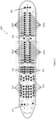
Figure 2 shows an overview of an aircraft cabin. - An overview of a
system 10 for charging an aircraft trolley 100 (also known as a cart) is shown inFigure 1 . Thesystem 10 includes atrolley 100. Thetrolley 100 haswheels 112 to be able to manoeuvre the trolley over anaircraft surface 120. Theaircraft surface 120 may include the floor of a passenger cabin, floor of a galley, or any other floor present in an aircraft cabin. - The
trolley 100 includes abattery 102 located within the interior of thetrolley 100. Thebattery 102 provides power to various points in thetrolley 100. For example, thebattery 102 could provide power to cooling/warming plates (not shown), payment stations (not shown), dispensing stations (not shown), charging stations for tablets/phones of cabin crew (not shown), and any other use where power is required. - The
trolley 100 also includes anexternal surface 106. As shown inFigure 1 , theexternal surface 106 is located at the bottom of thetrolley 100. Areceiver 104 extends from theexternal surface 106 towards theaircraft surface 120. As shown inFigure 1 , thereceiver 104 may be located between thewheels 112. It is envisaged that thereceiver 104 will extend to be as close as possible to theaircraft surface 120 without actually contacting theaircraft surface 120. Thereceiver 104 is configured to receive energy wirelessly from theaircraft surface 120, as described in more detail below. - As shown in
Figure 1 , theaircraft surface 120 may include afirst field generator 122a and asecond field generator 122b. It is envisaged that thefirst field generator 122a and thesecond field generator 122b are located beneath theaircraft surface 120 such that thetrolley 100 can be moved freely over theaircraft surface 120 without obstruction. Although there are only shown two field generators inFigure 1 , it is envisaged that more than two field generators would be provided at theaircraft surface 120 throughout the passenger cabin. For example, in an aircraft where there is an aisle between rows of seats, the field generators may be located at the aircraft surface along the aisle and between the rows of seats. The field generators may also be provided at an aircraft surface located in a galley of an aircraft (e.g. under the galley floor). The field generators may be separated by a distance along the aircraft surface - for example, the distance may be between 50cm and 220cm, or within 70cm and 200cm. - The
trolley 100 ofFigure 1 is shown positioned above thefirst field generator 122a. In this way, thefirst field generator 122a provides energy, via induction, to thereceiver 104 on thetrolley 100. Thereceiver 104 then provides the energy to thebattery 102 such that thebattery 102 can be charged whilst in use. As the cabin crew moves the trolley away from thefirst field generator 122a, the battery will not be charging and will be running on stored power. In order to avoid power of thebattery 102 running low, or depleting, during service, thetrolley 100 can be moved over thesecond field generator 122b such that thereceiver 104 receives energy, via induction, from thesecond field generator 122b. Thereceiver 104 then provides further energy to thebattery 102 such that power resources can be replenished. - The
trolley 100 described above allows the cabin crew to use the facilities that require power without contemplating whether the power in the battery is running low or nearing empty. In this way, the cabin crew can efficiently serve passengers without having to switch to another trolley that is fully charged or stop service altogether to re-charge thetrolley 100. Further, thesystem 10 allows for a smaller battery pack within thetrolley 100 as it can be charged whilst moving over the field generators provided at the aircraft surface. - An
aircraft cabin 200 is shown generally inFigure 2 . Theaircraft cabin 200 may include a number of field generators that correspond to thefield generators Figure 1 . For example, theaircraft cabin 200 might include a forward galley which may include a plurality of forwardgalley field generators 212. Theaircraft cabin 200 may also include a business class cabin (or first-class cabin) that may include a plurality of businessclass field generators 222. Each field generator of the plurality of businessclass field generators 222 may be separated by a distance of between 100cm to 210cm such that the trolley ofFigure 1 can contact the field generators during service as the trolley moves through theaircraft cabin 200. Theaircraft cabin 200 may also include a premium economy class cabin that may include a plurality of premium economyclass field generators 232. Each field generator of the plurality of premium economyclass field generators 232 may be separated by a distance of between 70cm and 100cm. Theaircraft cabin 200 may also include a forward economy class cabin that may include a plurality of forward economyclass field generators 242a. The forward economyclass field generators 242a may be separated by a distance of between 70cm and 90cm. As shown inFigure 2 , theaircraft cabin 200 may also include one or more middle galleys (only one is shown inFigure 2 ) that may include a plurality of middlegalley field generators 252. The middle galley may separate sections of the economy class cabin. Theaircraft cabin 200 may also include an aft economy class cabin that may include a plurality of aft economyclass field generators 242b. Each field generator of the plurality of aft economyclass field generators 242b may be separated by a distance of between 70cm and 90cm. Theaircraft cabin 200 may also include an aft galley that may also include a plurality of aftgalley field generators 262. The configuration as shown inFigure 2 is for a specific type of aircraft. However, it is to be understood that theaircraft cabin 200 may include one or more of the classes of cabins described above. The arrangement ofFigure 2 allows for the trolley ofFigure 1 to be charged as it is moved around the cabin during service. - Although this disclosure has been described in terms of preferred examples, it should be understood that these examples are illustrative only and that the claims are not limited to those examples. Those skilled in the art will be able to make modifications and alternatives in view of the disclosure which are contemplated as falling within the scope of the appended claims.
Claims (14)
- An aircraft trolley battery charging system comprising:a trolley (100), wherein the trolley includes a battery (102) and a receiver (104);an aircraft surface (120), wherein the trolley (100) is configured to move on the aircraft surface (120);at least one field generator (122a, 122b) provided at the aircraft surface (120).
- The aircraft trolley battery charging system of claim 1, wherein the at least one field generator (122a, 122b) is provided below the aircraft surface (120).
- The aircraft trolley battery charging system of claim 1 or 2, wherein the aircraft surface (120) is a floor of an aircraft cabin.
- The aircraft trolley battery charging system of any preceding claim, wherein the trolley (100) includes an external surface (106) and wherein the receiver (104) extends from the external surface (106) towards the aircraft surface (120).
- The aircraft trolley battery charging system of claim 4, wherein the receiver (104) is configured to extend to be as close as possible to the aircraft surface (120) without contacting the aircraft surface (120).
- An aircraft comprising:an aircraft cabin (200);an aircraft trolley battery charging system as claimed in any preceding claim.
- The aircraft of claim 6, wherein the aircraft cabin (200) includes one of a business class cabin, a premium economy class cabin, at least one economy class cabin and at least one galley.
- The aircraft of claim 7, wherein the at least one field generator (122a, 122b) includes at least one of a plurality of galley field generators (212, 252, 262), a plurality of business class field generators (222), a plurality of premium economy class field generators (232) and a plurality of economy class field generators (242a, 242b).
- The aircraft of claim 8, wherein the plurality of business class field generators (222) are separated by a distance of between 100cm to 210cm, wherein the plurality of premium economy class field generators (232) are separated by a distance of between 70cm and 100cm, and wherein the plurality of economy class field generators are separated by a distance of between 70cm and 90cm.
- A method of charging a battery in an aircraft trolley, the method comprising:providing a battery (102) and a receiver (104) in a trolley (100);providing at least one field generator (122a, 122b) at an aircraft surface (120), wherein the trolley (100) is configured to move on the aircraft surface (120);moving the receiver (104) over the at least one field generator (122a, 122b) such that energy may be transferred, via induction, from the at least one field generator (122a, 122b) to the receiver (104).
- The method of claim 10, wherein the at least one field generator (122a, 122b) is provided below the aircraft surface (120).
- The method of claim 10 or 11, wherein the aircraft surface (120) is a floor of an aircraft cabin.
- The method of any of claims 10, 11 or 12, wherein the trolley (100) includes an external surface (106) and wherein the receiver (104) extends from the external surface (106) towards the aircraft surface (120).
- The method of claim 13, wherein the receiver (104) is configured to extend to be as close as possible to the aircraft surface (120) without contacting the aircraft surface (120).
Priority Applications (2)
| Application Number | Priority Date | Filing Date | Title |
|---|---|---|---|
| EP22208365.1A EP4371880A1 (en) | 2022-11-18 | 2022-11-18 | Trolley/cart battery charging system |
| US18/511,247 US20240166352A1 (en) | 2022-11-18 | 2023-11-16 | Trolley/cart battery charging system |
Applications Claiming Priority (1)
| Application Number | Priority Date | Filing Date | Title |
|---|---|---|---|
| EP22208365.1A EP4371880A1 (en) | 2022-11-18 | 2022-11-18 | Trolley/cart battery charging system |
Publications (1)
| Publication Number | Publication Date |
|---|---|
| EP4371880A1 true EP4371880A1 (en) | 2024-05-22 |
Family
ID=84360185
Family Applications (1)
| Application Number | Title | Priority Date | Filing Date |
|---|---|---|---|
| EP22208365.1A Pending EP4371880A1 (en) | 2022-11-18 | 2022-11-18 | Trolley/cart battery charging system |
Country Status (2)
| Country | Link |
|---|---|
| US (1) | US20240166352A1 (en) |
| EP (1) | EP4371880A1 (en) |
Citations (4)
| Publication number | Priority date | Publication date | Assignee | Title |
|---|---|---|---|---|
| DE102018118023A1 (en) * | 2017-08-02 | 2019-02-07 | Panasonic Avionics Corporation | Device for use in a vehicle |
| US20190084604A1 (en) * | 2017-09-20 | 2019-03-21 | Airbus Operations Gmbh | Electrically powered transport cart combination for an aircraft cabin |
| US10775807B2 (en) * | 2017-06-28 | 2020-09-15 | Airbus Operations Gmbh | System for guidance of a robot through a passenger cabin of an aircraft |
| US20220089284A1 (en) * | 2020-09-24 | 2022-03-24 | Airbus Operations Gmbh | System for providing temperature-controlled water in an aircraft |
-
2022
- 2022-11-18 EP EP22208365.1A patent/EP4371880A1/en active Pending
-
2023
- 2023-11-16 US US18/511,247 patent/US20240166352A1/en active Pending
Patent Citations (4)
| Publication number | Priority date | Publication date | Assignee | Title |
|---|---|---|---|---|
| US10775807B2 (en) * | 2017-06-28 | 2020-09-15 | Airbus Operations Gmbh | System for guidance of a robot through a passenger cabin of an aircraft |
| DE102018118023A1 (en) * | 2017-08-02 | 2019-02-07 | Panasonic Avionics Corporation | Device for use in a vehicle |
| US20190084604A1 (en) * | 2017-09-20 | 2019-03-21 | Airbus Operations Gmbh | Electrically powered transport cart combination for an aircraft cabin |
| US20220089284A1 (en) * | 2020-09-24 | 2022-03-24 | Airbus Operations Gmbh | System for providing temperature-controlled water in an aircraft |
Also Published As
| Publication number | Publication date |
|---|---|
| US20240166352A1 (en) | 2024-05-23 |
Similar Documents
| Publication | Publication Date | Title |
|---|---|---|
| RU2647354C2 (en) | Method for power supply and power supply unit | |
| CN107627945A (en) | Modularization hovercar, hovercar system and hovercar sharing method | |
| US7614585B2 (en) | Multi-servicing and retractable bridge for an operational ground support system | |
| WO2011132202A1 (en) | Inflight catering apparatus | |
| US10775807B2 (en) | System for guidance of a robot through a passenger cabin of an aircraft | |
| US20240166352A1 (en) | Trolley/cart battery charging system | |
| US20070007391A1 (en) | Isolated crew deck for an operational ground suppport system | |
| RU216350U1 (en) | VEHICLE | |
| US12617563B2 (en) | Payload (variants) and air transport system (variants) comprising same | |
| US7549607B2 (en) | Aircraft having a dual floor servicing system associated with an operational ground support system | |
| GB2598899A (en) | Method of providing electrical power to a battery powered self-propelled vehicle, an energy storage vehicle and a logistics system | |
| GB2571068A (en) | Improved vehicle, charging system and components | |
| Brühl et al. | Assessment of minimum ground time for air taxis based on turnaround critical path modeling | |
| US12151815B2 (en) | Suspended serving system and methods | |
| Kumar et al. | Hyperloop high speed of transportation | |
| GB2598900A (en) | Intelligent power sharing vehicles | |
| KR20230055713A (en) | Mobility operating system to circumstances | |
| US10882639B2 (en) | Transportation system, and related system and method for transferring luggage into a transportation system | |
| Avery | Aircraft load planning and control | |
| KR101328056B1 (en) | Method for platooning of electric car | |
| Ehrich et al. | DLR design challenge 2024: design of a cost and energy efficient regional aircraft | |
| EP4516671A1 (en) | Onboard stowage of hand luggage | |
| WO2025062189A1 (en) | Aerial vehicle (variants) | |
| Gorton | Advanced Air Mobility (aka Air Taxis and Flying Cars) | |
| RU2136546C1 (en) | Method of aircraft transportation of passengers |
Legal Events
| Date | Code | Title | Description |
|---|---|---|---|
| PUAI | Public reference made under article 153(3) epc to a published international application that has entered the european phase |
Free format text: ORIGINAL CODE: 0009012 |
|
| STAA | Information on the status of an ep patent application or granted ep patent |
Free format text: STATUS: THE APPLICATION HAS BEEN PUBLISHED |
|
| AK | Designated contracting states |
Kind code of ref document: A1 Designated state(s): AL AT BE BG CH CY CZ DE DK EE ES FI FR GB GR HR HU IE IS IT LI LT LU LV MC ME MK MT NL NO PL PT RO RS SE SI SK SM TR |
|
| STAA | Information on the status of an ep patent application or granted ep patent |
Free format text: STATUS: REQUEST FOR EXAMINATION WAS MADE |
|
| 17P | Request for examination filed |
Effective date: 20241122 |
|
| RBV | Designated contracting states (corrected) |
Designated state(s): AL AT BE BG CH CY CZ DE DK EE ES FI FR GB GR HR HU IE IS IT LI LT LU LV MC ME MK MT NL NO PL PT RO RS SE SI SK SM TR |
|
| STAA | Information on the status of an ep patent application or granted ep patent |
Free format text: STATUS: EXAMINATION IS IN PROGRESS |
|
| 17Q | First examination report despatched |
Effective date: 20251209 |