EP4371875A1 - Fiber optic slat flap system and control lever - Google Patents
Fiber optic slat flap system and control lever Download PDFInfo
- Publication number
- EP4371875A1 EP4371875A1 EP23210977.7A EP23210977A EP4371875A1 EP 4371875 A1 EP4371875 A1 EP 4371875A1 EP 23210977 A EP23210977 A EP 23210977A EP 4371875 A1 EP4371875 A1 EP 4371875A1
- Authority
- EP
- European Patent Office
- Prior art keywords
- optical fiber
- wing
- cam
- phase
- optical
- Prior art date
- Legal status (The legal status is an assumption and is not a legal conclusion. Google has not performed a legal analysis and makes no representation as to the accuracy of the status listed.)
- Granted
Links
Images


Classifications
-
- B—PERFORMING OPERATIONS; TRANSPORTING
- B64—AIRCRAFT; AVIATION; COSMONAUTICS
- B64C—AEROPLANES; HELICOPTERS
- B64C13/00—Control systems or transmitting systems for actuating flying-control surfaces, lift-increasing flaps, air brakes, or spoilers
- B64C13/02—Initiating means
- B64C13/04—Initiating means actuated personally
- B64C13/042—Initiating means actuated personally operated by hand
- B64C13/0425—Initiating means actuated personally operated by hand for actuating trailing or leading edge flaps, air brakes or spoilers
-
- B—PERFORMING OPERATIONS; TRANSPORTING
- B64—AIRCRAFT; AVIATION; COSMONAUTICS
- B64C—AEROPLANES; HELICOPTERS
- B64C13/00—Control systems or transmitting systems for actuating flying-control surfaces, lift-increasing flaps, air brakes, or spoilers
- B64C13/02—Initiating means
- B64C13/16—Initiating means actuated automatically, e.g. responsive to gust detectors
-
- B—PERFORMING OPERATIONS; TRANSPORTING
- B64—AIRCRAFT; AVIATION; COSMONAUTICS
- B64C—AEROPLANES; HELICOPTERS
- B64C13/00—Control systems or transmitting systems for actuating flying-control surfaces, lift-increasing flaps, air brakes, or spoilers
- B64C13/24—Transmitting means
- B64C13/38—Transmitting means with power amplification
- B64C13/50—Transmitting means with power amplification using electrical energy
- B64C13/503—Fly-by-Wire
-
- G—PHYSICS
- G02—OPTICS
- G02B—OPTICAL ELEMENTS, SYSTEMS OR APPARATUS
- G02B6/00—Light guides; Structural details of arrangements comprising light guides and other optical elements, e.g. couplings
- G02B6/10—Light guides; Structural details of arrangements comprising light guides and other optical elements, e.g. couplings of the optical waveguide type
- G02B6/12—Light guides; Structural details of arrangements comprising light guides and other optical elements, e.g. couplings of the optical waveguide type of the integrated circuit kind
- G02B2006/12133—Functions
- G02B2006/12138—Sensor
-
- G—PHYSICS
- G02—OPTICS
- G02F—OPTICAL DEVICES OR ARRANGEMENTS FOR THE CONTROL OF LIGHT BY MODIFICATION OF THE OPTICAL PROPERTIES OF THE MEDIA OF THE ELEMENTS INVOLVED THEREIN; NON-LINEAR OPTICS; FREQUENCY-CHANGING OF LIGHT; OPTICAL LOGIC ELEMENTS; OPTICAL ANALOGUE/DIGITAL CONVERTERS
- G02F1/00—Devices or arrangements for the control of the intensity, colour, phase, polarisation or direction of light arriving from an independent light source, e.g. switching, gating or modulating; Non-linear optics
- G02F1/01—Devices or arrangements for the control of the intensity, colour, phase, polarisation or direction of light arriving from an independent light source, e.g. switching, gating or modulating; Non-linear optics for the control of the intensity, phase, polarisation or colour
- G02F1/0128—Devices or arrangements for the control of the intensity, colour, phase, polarisation or direction of light arriving from an independent light source, e.g. switching, gating or modulating; Non-linear optics for the control of the intensity, phase, polarisation or colour based on electro-mechanical, magneto-mechanical, elasto-optic effects
- G02F1/0131—Devices or arrangements for the control of the intensity, colour, phase, polarisation or direction of light arriving from an independent light source, e.g. switching, gating or modulating; Non-linear optics for the control of the intensity, phase, polarisation or colour based on electro-mechanical, magneto-mechanical, elasto-optic effects based on photo-elastic effects, e.g. mechanically induced birefringence
- G02F1/0134—Devices or arrangements for the control of the intensity, colour, phase, polarisation or direction of light arriving from an independent light source, e.g. switching, gating or modulating; Non-linear optics for the control of the intensity, phase, polarisation or colour based on electro-mechanical, magneto-mechanical, elasto-optic effects based on photo-elastic effects, e.g. mechanically induced birefringence in optical waveguides
Definitions
- Embodiments of the present disclosure relate to airplane operations and, more particular, to a system and method for controlling the positions of a slat and/or a flap on a wing of an airplane.
- An airplane wing generally includes a slat at its forward surface and a flap at its anterior.
- the positions of the slat and the flap can be controlled for different flight operations.
- Current slat/flap control systems operate by controlling a position of a magnet within an air gap of a transformer. The effectiveness of such control system can deteriorate over time due to changes the airgap, etc. There is a therefore a need for a longer lasting and more reliable control system.
- a method of controlling a wing of an airplane includes passing a light having an input optical phase through an optical fiber, applying an external force to the optical fiber to cause the light exiting the optical fiber to have output optical phase, determining a phase shift between the input optical phase and the output optical phase, and controlling the wing of the airplane based on the phase shift.
- controlling the wing further includes adjusting one of a slat and a flap of the wing to a position corresponding to the phase shift.
- the method further includes rotating a cam having a cam surface in contact with the optical fiber to apply the external force to the optical fiber.
- a magnitude of the external force is related to a radius of the cam at a circumferential location of the cam surface that is in contact with the optical fiber.
- the method further includes rotating the cam using a lever.
- controlling the wing further includes sending a command signal to the wing, wherein the command signal is an optical signal.
- the method further includes bending the optical fiber to produce the phase shift using the external force.
- a control system for a wing of an airplane includes an optical fiber configured to receive light having an input optical phase. a bending device that applies an external force on the optical fiber, wherein the external force causes the light exiting the optical fiber to have an output optical phase, and a processor configured to determine a phase shift between the input optical phase and the output optical phase and control the wing based on the phase shift.
- the processor is configured to control the wing by adjusting one of a slat and a flap to a position based on by the phase shift.
- the bending device further comprises a cam having a cam surface in contact with the optical fiber.
- the cam is configured to rotate one to apply the external force to the optical fiber.
- a magnitude of the external force is related to a radius of the cam at a circumferential location of the cam surface that is in contact with the optical fiber.
- control system further includes a lever for rotating the cam.
- a detent position of the cam corresponds to a selected phase shift of the light in the optical fiber.
- the processor is further configured to send a command signal to the wing, wherein the command signal is an optical signal.
- the airplane 100 includes a fuselage 102 and wings 104.
- Each wing 104 includes a slat 106 and a flap 108.
- a wing 104 can include a plurality of slats and/or a plurality of flaps 108.
- a slat 106 is a surface on a forward or leading edge of the wing 104. When deployed, a slat 106 allows the wing 104 to operate at a higher angle of attack.
- a flap 108 is a surface on a trailing edge of the wing 104 and is used to increase a drag on the airplane 100 when deployed.
- a cockpit 110 sends signals for controlling the operation of the slats 106 and the flaps.
- the cockpit 110 sends an optical slat/flap command along one or more optical fibers.
- a slat control optical fiber 112 extends along a wing 104 to one or more of the slats 106 and a flap control optical fiber 114 extends along a wing 104 to one or more of the flaps 108.
- FIG. 2 shows a schematic diagram of a control system 200 location in the cockpit 110.
- the control system 200 includes a position selector 202 and an interrogator unit 204.
- the position selector 202 is used to selects a position for a slat 106 and/or a flap 108.
- the interrogator unit 204 includes a light source 206, such as a laser, a light detector 208, and a processor 210.
- the processor 210 can send an electrical signal to the light source 206, which generates a light having an input phase in response.
- the light is input to an optical fiber 212 that passes from the light source 206, through the position selector 202 and then on to the light detector 208.
- the position selector 202 can alter, adjust or control an optical phase of the light passing through the optical fiber 212.
- the light received at the light detector 208 has an output optical phase.
- the output optical phase can be the same as the input optical phase or can be different from the input optical phase depending on whether or not an adjustment is made to the optical phase at the position selector 202.
- the light detector 208 sends an electrical signal to the processor 210 in response to the received light.
- the electrical signal includes information on the output phase of the received light.
- the processor 210 determines a difference of phase shift between the input phase and the output phase.
- the processor 210 selects a corresponding position for one or more of the slats 106 and flaps 108 and sends a command signal to the one or more of the slats 106 and flaps 108 in order to place them in the selected position.
- the processor 210 can match the difference between input phase and output phases to a corresponding slat/flap position using a lookup table, an algorithm, etc.
- the command signal can be an optical signal that is sent to the slats 106 and/or flaps 108 along an optical fiber.
- FIG. 3 shows a diagram 300 of a path of the optical fiber 212, in an embodiment.
- the optical fiber 212 extends from the light source 206 to light detector 208 and passes through a modulation zone 302.
- a polarizer 304 is at an input end of the modulation zone 302 and an analyzer 306 is at an output end of the modulation zone 302.
- the polarizer 304 produces polarized light in the modulation zone 302.
- the analyzer 306 is used to determine the polarity of the light exiting the modulation zone 302.
- an external force can be applied to the optical fiber 212 causing the optical fiber to bend.
- the phase of the light in the modulation zone 302 changes in proportion to the degree of bending produced by the external force.
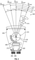
- FIG. 4 is a diagram 400 illustrating details of the position selector 202.
- the position selector 202 includes a housing 402 having a fiber entrance 404 and a fiber exit 406.
- the optical fiber 212 passes through the fiber entrance 404 and runs along a pressure modulation block 408 before passing through the fiber exit 406.
- the pressure modulation block 408 corresponds to the modulation zone 302.
- the pressure modulation block 408 can suspend the modulation zone 302 of the optical fiber 212, allowing the optical fiber 212 to bend when an external force is applied.
- a cam 410 is in contact with the modulation zone 302 of the optical fiber 212 at the modulation block 308.
- the cam 410 acts as a bending device that applies an external force on the optical fiber 212 to bend the optical fiber 212.
- the cam 410 has a cam surface 412 that is in contact with the optical fiber 212 in the modulation zone 302.
- the cam 410 can be rotated so that the cam surface 412 makes contact with the optical fiber 212 at different circumferential locations of the cam surface 412. Illustrative circumferential locations are labelled from C1 to C5.
- a lever 414 is connected to the cam 410 and is used to rotate the cam 410.
- Each circumferential location C1-C5 can be in contact with the optical fiber 212 when the cam 410 (and lever 414) is in a detent position.
- each detent position of the cam 410 corresponds to a selected phase shift of the light in the optical fiber 212.
- the radius r 1 of the cam 410 at the first circumferential location C1 is a smallest radius and the radius r 5 at the fifth circumferential location C5 is a largest radius, with the radii increasing sequentially from C1 to C5.
- the rotational axis 416 of the cam 410 is held at a fixed distance from the optical fiber 212.
- rotating the cam 410 causes different circumferential locations C1 through C5 to contact the optical fiber 212, with each circumferential location C1-C5 introducing a different external force on the optical fiber 212 to bend the optical fiber 212, thereby introducing a different phase shift of the light in the optical fiber 212.
- the magnitude of the external force is related to the radius of the cam 410 at the circumferential location of the cam surface 412 in contact with the optical fiber 212.
- circumferential location C1 can correspond to no external force and thus no phase shift
- circumferential location C5 can correspond to a largest external force and thus largest phase shift.
- a second optical fiber 420 can be provided alongside optical fiber 212.
- the second optical fiber 420 is affected by forces applied by the cam 410 similar to the optical fiber 212 and thus provides a redundant signal which can be used for quality control.
Landscapes
- Engineering & Computer Science (AREA)
- Automation & Control Theory (AREA)
- Aviation & Aerospace Engineering (AREA)
- Mechanical Light Control Or Optical Switches (AREA)
- Physics & Mathematics (AREA)
- General Physics & Mathematics (AREA)
Abstract
Description
- Embodiments of the present disclosure relate to airplane operations and, more particular, to a system and method for controlling the positions of a slat and/or a flap on a wing of an airplane.
- An airplane wing generally includes a slat at its forward surface and a flap at its anterior. The positions of the slat and the flap can be controlled for different flight operations. Current slat/flap control systems operate by controlling a position of a magnet within an air gap of a transformer. The effectiveness of such control system can deteriorate over time due to changes the airgap, etc. There is a therefore a need for a longer lasting and more reliable control system.
- According to one aspect, a method of controlling a wing of an airplane is disclosed. The method includes passing a light having an input optical phase through an optical fiber, applying an external force to the optical fiber to cause the light exiting the optical fiber to have output optical phase, determining a phase shift between the input optical phase and the output optical phase, and controlling the wing of the airplane based on the phase shift.
- In embodiments, controlling the wing further includes adjusting one of a slat and a flap of the wing to a position corresponding to the phase shift.
- In embodiments, the method further includes rotating a cam having a cam surface in contact with the optical fiber to apply the external force to the optical fiber.
- In embodiments, a magnitude of the external force is related to a radius of the cam at a circumferential location of the cam surface that is in contact with the optical fiber.
- In embodiments, the method further includes rotating the cam using a lever.
- In embodiments, controlling the wing further includes sending a command signal to the wing, wherein the command signal is an optical signal.
- In embodiments, the method further includes bending the optical fiber to produce the phase shift using the external force.
- According to another aspect, a control system for a wing of an airplane is disclosed. The control system includes an optical fiber configured to receive light having an input optical phase. a bending device that applies an external force on the optical fiber, wherein the external force causes the light exiting the optical fiber to have an output optical phase, and a processor configured to determine a phase shift between the input optical phase and the output optical phase and control the wing based on the phase shift.
- In embodiments, the processor is configured to control the wing by adjusting one of a slat and a flap to a position based on by the phase shift.
- In embodiments, the bending device further comprises a cam having a cam surface in contact with the optical fiber.
- In embodiments, the cam is configured to rotate one to apply the external force to the optical fiber.
- In embodiments, a magnitude of the external force is related to a radius of the cam at a circumferential location of the cam surface that is in contact with the optical fiber.
- In embodiments, the control system further includes a lever for rotating the cam.
- In embodiments, a detent position of the cam corresponds to a selected phase shift of the light in the optical fiber.
- In embodiments, the processor is further configured to send a command signal to the wing, wherein the command signal is an optical signal.
-
- The following descriptions should not be considered limiting in any way. With reference to the accompanying drawings, like elements are numbered alike:
-
FIG. 1 shows an airplane in a plan view; -
FIG. 2 shows a schematic diagram of a control system location in a cockpit of the airplane; -
FIG. 3 shows a diagram of a path of an optical fiber of the control system, in an embodiment; and -
FIG. 4 is a diagram illustrating details of a position selector of the control system. - A detailed description of one or more embodiments of the disclosed apparatus and method are presented herein by way of exemplification and not limitation with reference to the Figures.
- With reference now to
FIG. 1 , anairplane 100 is shown in a plan view. Theairplane 100 includes afuselage 102 andwings 104. Eachwing 104 includes aslat 106 and aflap 108. In various embodiments, awing 104 can include a plurality of slats and/or a plurality offlaps 108. Aslat 106 is a surface on a forward or leading edge of thewing 104. When deployed, aslat 106 allows thewing 104 to operate at a higher angle of attack. Aflap 108 is a surface on a trailing edge of thewing 104 and is used to increase a drag on theairplane 100 when deployed. - A
cockpit 110 sends signals for controlling the operation of theslats 106 and the flaps. In various embodiments, thecockpit 110 sends an optical slat/flap command along one or more optical fibers. As shown inFIG. 1 , a slat controloptical fiber 112 extends along awing 104 to one or more of theslats 106 and a flap controloptical fiber 114 extends along awing 104 to one or more of theflaps 108. -
FIG. 2 shows a schematic diagram of acontrol system 200 location in thecockpit 110. Thecontrol system 200 includes aposition selector 202 and aninterrogator unit 204. Theposition selector 202 is used to selects a position for aslat 106 and/or aflap 108. Theinterrogator unit 204 includes alight source 206, such as a laser, alight detector 208, and aprocessor 210. Theprocessor 210 can send an electrical signal to thelight source 206, which generates a light having an input phase in response. The light is input to anoptical fiber 212 that passes from thelight source 206, through theposition selector 202 and then on to thelight detector 208. Theposition selector 202 can alter, adjust or control an optical phase of the light passing through theoptical fiber 212. Thus, the light received at thelight detector 208 has an output optical phase. The output optical phase can be the same as the input optical phase or can be different from the input optical phase depending on whether or not an adjustment is made to the optical phase at theposition selector 202. Thelight detector 208 sends an electrical signal to theprocessor 210 in response to the received light. The electrical signal includes information on the output phase of the received light. Theprocessor 210 determines a difference of phase shift between the input phase and the output phase. Based on the difference, theprocessor 210 selects a corresponding position for one or more of theslats 106 andflaps 108 and sends a command signal to the one or more of theslats 106 and flaps 108 in order to place them in the selected position. Theprocessor 210 can match the difference between input phase and output phases to a corresponding slat/flap position using a lookup table, an algorithm, etc. The command signal can be an optical signal that is sent to theslats 106 and/orflaps 108 along an optical fiber. -
FIG. 3 shows a diagram 300 of a path of theoptical fiber 212, in an embodiment. Theoptical fiber 212 extends from thelight source 206 tolight detector 208 and passes through amodulation zone 302. Apolarizer 304 is at an input end of themodulation zone 302 and ananalyzer 306 is at an output end of themodulation zone 302. Thepolarizer 304 produces polarized light in themodulation zone 302. Theanalyzer 306 is used to determine the polarity of the light exiting themodulation zone 302. In themodulation zone 302, an external force can be applied to theoptical fiber 212 causing the optical fiber to bend. The phase of the light in themodulation zone 302 changes in proportion to the degree of bending produced by the external force. -
FIG. 4 is a diagram 400 illustrating details of theposition selector 202. Theposition selector 202 includes ahousing 402 having afiber entrance 404 and afiber exit 406. Theoptical fiber 212 passes through thefiber entrance 404 and runs along apressure modulation block 408 before passing through thefiber exit 406. Thepressure modulation block 408 corresponds to themodulation zone 302. Thepressure modulation block 408 can suspend themodulation zone 302 of theoptical fiber 212, allowing theoptical fiber 212 to bend when an external force is applied. Acam 410 is in contact with themodulation zone 302 of theoptical fiber 212 at the modulation block 308. Thecam 410 acts as a bending device that applies an external force on theoptical fiber 212 to bend theoptical fiber 212. Thecam 410 has acam surface 412 that is in contact with theoptical fiber 212 in themodulation zone 302. Thecam 410 can be rotated so that thecam surface 412 makes contact with theoptical fiber 212 at different circumferential locations of thecam surface 412. Illustrative circumferential locations are labelled from C1 to C5. Alever 414 is connected to thecam 410 and is used to rotate thecam 410. Each circumferential location C1-C5 can be in contact with theoptical fiber 212 when the cam 410 (and lever 414) is in a detent position. Thus, each detent position of thecam 410 corresponds to a selected phase shift of the light in theoptical fiber 212. - The radius r1 of the
cam 410 at the first circumferential location C1 is a smallest radius and the radius r5 at the fifth circumferential location C5 is a largest radius, with the radii increasing sequentially from C1 to C5. Therotational axis 416 of thecam 410 is held at a fixed distance from theoptical fiber 212. Thus, rotating thecam 410 causes different circumferential locations C1 through C5 to contact theoptical fiber 212, with each circumferential location C1-C5 introducing a different external force on theoptical fiber 212 to bend theoptical fiber 212, thereby introducing a different phase shift of the light in theoptical fiber 212. The magnitude of the external force is related to the radius of thecam 410 at the circumferential location of thecam surface 412 in contact with theoptical fiber 212. As an illustrative example, circumferential location C1 can correspond to no external force and thus no phase shift, while circumferential location C5 can correspond to a largest external force and thus largest phase shift. - As shown in
FIG. 4 , a secondoptical fiber 420 can be provided alongsideoptical fiber 212. The secondoptical fiber 420 is affected by forces applied by thecam 410 similar to theoptical fiber 212 and thus provides a redundant signal which can be used for quality control. - The term "about" is intended to include the degree of error associated with measurement of the particular quantity based upon the equipment available at the time of filing the application.
- The terminology used herein is for the purpose of describing particular embodiments only and is not intended to be limiting of the present disclosure. As used herein, the singular forms "a", "an" and "the" are intended to include the plural forms as well, unless the context clearly indicates otherwise. It will be further understood that the terms "comprises" and/or "comprising," when used in this specification, specify the presence of stated features, integers, steps, operations, elements, and/or components, but do not preclude the presence or addition of one or more other features, integers, steps, operations, element components, and/or groups thereof.
- While the present disclosure has been described with reference to an exemplary embodiment or embodiments, it will be understood by those skilled in the art that various changes may be made without departing from the scope of the invention as defined by the claims. In addition, many modifications may be made to adapt a particular situation or material to the teachings of the present disclosure without departing from the scope of the claims.
Claims (15)
- A method of controlling a wing of an airplane, comprising:passing a light having an input optical phase through an optical fiber (112, 114);applying an external force to the optical fiber to cause the light exiting the optical fiber to have output optical phase;determining a phase shift between the input optical phase and the output optical phase; andcontrolling the wing (104) of the airplane based on the phase shift.
- The method of claim 1, wherein controlling the wing further comprises adjusting one of a slat (106) and a flap (108) of the wing to a position corresponding to the phase shift.
- The method of claim 1 or 2, further comprising rotating a cam (410) having a cam surface (412) in contact with the optical fiber to apply the external force to the optical fiber.
- The method of claim 3, wherein a magnitude of the external force is related to a radius of the cam at a circumferential location of the cam surface that is in contact with the optical fiber.
- The method of claim 3, further comprising rotating the cam using a lever (414).
- The method of any preceding claim, wherein controlling the wing further comprises sending a command signal to the wing, wherein the command signal is an optical signal.
- The method of any preceding claim, further comprising bending the optical fiber to produce the phase shift using the external force.
- A control system for a wing of an airplane, comprising:an optical fiber (112, 114)configured to receive light having an input optical phase;a bending device (410) that applies an external force on the optical fiber, wherein the external force causes the light exiting the optical fiber to have an output optical phase; anda processor (210) configured to determine a phase shift between the input optical phase and the output optical phase and control the wing based on the phase shift.
- The control system of claim 8, wherein the processor is configured to control the wing by adjusting one of a slat and a flap to a position based on by the phase shift.
- The control system of claim 8 or 9, wherein the bending device further comprises a cam (410) having a cam surface (412) in contact with the optical fiber.
- The control system of claim 10, wherein the cam is configured to rotate one to apply the external force to the optical fiber.
- The control system of claim 11, wherein a magnitude of the external force is related to a radius of the cam at a circumferential location of the cam surface that is in contact with the optical fiber.
- The control system of claim 11 or 12, further comprising a lever (414) for rotating the cam.
- The control system of claim 11, 12 or 13, wherein a detent position of the cam corresponds to a selected phase shift of the light in the optical fiber.
- The control system of any of claims 8 to 11, wherein the processor is further configured to send a command signal to the wing, wherein the command signal is an optical signal.
Applications Claiming Priority (1)
| Application Number | Priority Date | Filing Date | Title |
|---|---|---|---|
| US17/990,977 US12351295B2 (en) | 2022-11-21 | 2022-11-21 | Fiber optic slat flap system and control lever |
Publications (2)
| Publication Number | Publication Date |
|---|---|
| EP4371875A1 true EP4371875A1 (en) | 2024-05-22 |
| EP4371875B1 EP4371875B1 (en) | 2025-08-20 |
Family
ID=88874665
Family Applications (1)
| Application Number | Title | Priority Date | Filing Date |
|---|---|---|---|
| EP23210977.7A Active EP4371875B1 (en) | 2022-11-21 | 2023-11-20 | Fiber optic slat flap system and control lever |
Country Status (2)
| Country | Link |
|---|---|
| US (1) | US12351295B2 (en) |
| EP (1) | EP4371875B1 (en) |
Families Citing this family (1)
| Publication number | Priority date | Publication date | Assignee | Title |
|---|---|---|---|---|
| US12337990B2 (en) * | 2023-01-13 | 2025-06-24 | Hamilton Sundstrand Corporation | Fiber optic actuator overload trip sensor |
Citations (4)
| Publication number | Priority date | Publication date | Assignee | Title |
|---|---|---|---|---|
| US20040128038A1 (en) * | 2002-10-26 | 2004-07-01 | Martin Richter | Arrangement for generating control commands for actuating flaps and slats of an aircraft |
| EP3461740A1 (en) * | 2017-09-28 | 2019-04-03 | Hamilton Sundstrand Corporation | Position detection system for a slat flap lever control |
| US20200086972A1 (en) * | 2018-09-17 | 2020-03-19 | UAVOS Holdings Limited | Method for controlling an aircraft, and an aircraft (variants) |
| US20200213012A1 (en) * | 2019-01-02 | 2020-07-02 | The Boeing Company | Embedded Fiber Optic Sensor System |
Family Cites Families (18)
| Publication number | Priority date | Publication date | Assignee | Title |
|---|---|---|---|---|
| US4333009A (en) * | 1979-12-10 | 1982-06-01 | Bertea Corporation | Optical position transducer |
| EP0046875B1 (en) | 1980-09-02 | 1989-09-20 | Messerschmitt-Bölkow-Blohm Gesellschaft mit beschränkter Haftung | Control signal transmission device, especially for aircraft |
| CA1184271A (en) * | 1981-03-25 | 1985-03-19 | Joseph R. Maciolek | Solarized optical digital servo control system |
| DE3939132A1 (en) | 1989-11-27 | 1991-05-29 | Bodenseewerk Geraetetech | POSITION SENSOR FOR LANDING FLAP LEVER ON AIRCRAFT |
| DE4302670A1 (en) * | 1993-01-30 | 1994-08-04 | Valentron Ag | Determining position or setting of control column corresp. to certain control order |
| US5875818A (en) * | 1994-09-23 | 1999-03-02 | The Boeing Company | Opto-electric/hydraulic servocactuation |
| KR100274075B1 (en) * | 1998-05-09 | 2001-01-15 | 서원석 | Optical fiber grating and optical element using the same |
| US8022835B2 (en) * | 2005-10-24 | 2011-09-20 | Nathan John Coleman | Optic system using spectral character shift for communication between optic input devices and reader devices for control systems and sensors for pressure, force, displacement, or chemical condition |
| US8087619B2 (en) | 2008-07-30 | 2012-01-03 | Honeywell International, Inc. | Active control stick assembly including traction drive |
| WO2010123566A1 (en) * | 2009-04-22 | 2010-10-28 | Lxdata Inc. | Pressure sensor arrangement using an optical fiber and methodologies for performing an analysis of a subterranean formation |
| US9327826B2 (en) | 2012-10-25 | 2016-05-03 | Textron Innovations Inc. | Self-centering aircraft flap position command apparatus |
| EP3066424A1 (en) * | 2013-12-11 | 2016-09-14 | Moog Inc. | Fiber optic sensing and control system |
| GB201409230D0 (en) * | 2014-05-23 | 2014-07-09 | Qinetiq Ltd | Improvements to sensors |
| US20190337634A1 (en) * | 2018-05-01 | 2019-11-07 | Sikorsky Aircraft Corporation | Controlling an Aircraft Based on Detecting Control Element Damage |
| GB2574442B (en) * | 2018-06-06 | 2021-10-27 | Ge Aviat Systems Ltd | Method and apparatus for reducing aircraft wing bending moment |
| US10712212B2 (en) * | 2018-06-14 | 2020-07-14 | Kidde Technologies, Inc. | Overheat detection using a fiber bragg gratings array by time-of-flight |
| KR102359024B1 (en) * | 2020-06-11 | 2022-02-04 | 연세대학교 산학협력단 | Bragg Grating Based Optical Fiber Sensor Measuring Inflection Point Vector of Chiral Motion and Manufacturing Method Thereof |
| GB2608145A (en) * | 2021-06-23 | 2022-12-28 | Airbus Operations Ltd | Optical sensing system |
-
2022
- 2022-11-21 US US17/990,977 patent/US12351295B2/en active Active
-
2023
- 2023-11-20 EP EP23210977.7A patent/EP4371875B1/en active Active
Patent Citations (4)
| Publication number | Priority date | Publication date | Assignee | Title |
|---|---|---|---|---|
| US20040128038A1 (en) * | 2002-10-26 | 2004-07-01 | Martin Richter | Arrangement for generating control commands for actuating flaps and slats of an aircraft |
| EP3461740A1 (en) * | 2017-09-28 | 2019-04-03 | Hamilton Sundstrand Corporation | Position detection system for a slat flap lever control |
| US20200086972A1 (en) * | 2018-09-17 | 2020-03-19 | UAVOS Holdings Limited | Method for controlling an aircraft, and an aircraft (variants) |
| US20200213012A1 (en) * | 2019-01-02 | 2020-07-02 | The Boeing Company | Embedded Fiber Optic Sensor System |
Also Published As
| Publication number | Publication date |
|---|---|
| US20240166334A1 (en) | 2024-05-23 |
| US12351295B2 (en) | 2025-07-08 |
| EP4371875B1 (en) | 2025-08-20 |
Similar Documents
| Publication | Publication Date | Title |
|---|---|---|
| EP4371875B1 (en) | Fiber optic slat flap system and control lever | |
| CN112740094B (en) | A mirror assembly for light steering | |
| JP6987581B2 (en) | Systems and methods for correcting twists in aircraft wings | |
| EP2818835A2 (en) | Control surface calibration system | |
| US10969796B2 (en) | Autopilot nonlinear compensation | |
| JP3965243B2 (en) | Control device | |
| CN113513952A (en) | Electric steering engine, zero position calibration method and device for electric steering engine and storage medium | |
| EP3461740A1 (en) | Position detection system for a slat flap lever control | |
| GB1575896A (en) | Speed variable limits in fail-safe actuators | |
| US10988237B1 (en) | Feed forward equalization control for active-active redundant actuation systems | |
| US10429880B2 (en) | Magnetic positive detent for helicopter pilot input | |
| EP3792178A1 (en) | Dual actuator hydraulic pitch-lock propeller system | |
| US20050234608A1 (en) | Method for an aircraft navigational aid and corresponding device | |
| US9776708B2 (en) | Method of managing discontinuities in vehicle control following a control transition, and a vehicle | |
| EP4400822B1 (en) | Fiber optic actuator overload trip sensor | |
| US10401154B2 (en) | Apparatus and method to detect aircraft wing deflection and twist during flight | |
| US8406582B2 (en) | Optical switch and method for controlling optical switch | |
| JPH07196097A (en) | Method and device for checking safety of control system of aerodyne on ground | |
| EP3722211A1 (en) | Dynamic illumination system for runway illumination | |
| WO2005060346A2 (en) | High precision wide-angle electro-optical positioning system and method | |
| US10948363B2 (en) | Overheat testing apparatus for optical fiber | |
| EP4075098B1 (en) | Unusual attitude recovery symbology | |
| KR20020045562A (en) | Method for operating an air-to-air missile and corresponding missile with autonomous or semi-autonomous modes | |
| EP1011036A1 (en) | Flight control system | |
| US20250266741A1 (en) | Method, system, actuator and aircraft |
Legal Events
| Date | Code | Title | Description |
|---|---|---|---|
| PUAI | Public reference made under article 153(3) epc to a published international application that has entered the european phase |
Free format text: ORIGINAL CODE: 0009012 |
|
| STAA | Information on the status of an ep patent application or granted ep patent |
Free format text: STATUS: THE APPLICATION HAS BEEN PUBLISHED |
|
| AK | Designated contracting states |
Kind code of ref document: A1 Designated state(s): AL AT BE BG CH CY CZ DE DK EE ES FI FR GB GR HR HU IE IS IT LI LT LU LV MC ME MK MT NL NO PL PT RO RS SE SI SK SM TR |
|
| STAA | Information on the status of an ep patent application or granted ep patent |
Free format text: STATUS: REQUEST FOR EXAMINATION WAS MADE |
|
| 17P | Request for examination filed |
Effective date: 20241121 |
|
| RBV | Designated contracting states (corrected) |
Designated state(s): AL AT BE BG CH CY CZ DE DK EE ES FI FR GB GR HR HU IE IS IT LI LT LU LV MC ME MK MT NL NO PL PT RO RS SE SI SK SM TR |
|
| GRAP | Despatch of communication of intention to grant a patent |
Free format text: ORIGINAL CODE: EPIDOSNIGR1 |
|
| STAA | Information on the status of an ep patent application or granted ep patent |
Free format text: STATUS: GRANT OF PATENT IS INTENDED |
|
| RIC1 | Information provided on ipc code assigned before grant |
Ipc: G05D 1/49 20240101ALI20250314BHEP Ipc: B64C 13/50 20060101AFI20250314BHEP |
|
| INTG | Intention to grant announced |
Effective date: 20250326 |
|
| GRAS | Grant fee paid |
Free format text: ORIGINAL CODE: EPIDOSNIGR3 |
|
| GRAA | (expected) grant |
Free format text: ORIGINAL CODE: 0009210 |
|
| STAA | Information on the status of an ep patent application or granted ep patent |
Free format text: STATUS: THE PATENT HAS BEEN GRANTED |
|
| AK | Designated contracting states |
Kind code of ref document: B1 Designated state(s): AL AT BE BG CH CY CZ DE DK EE ES FI FR GB GR HR HU IE IS IT LI LT LU LV MC ME MK MT NL NO PL PT RO RS SE SI SK SM TR |
|
| REG | Reference to a national code |
Ref country code: GB Ref legal event code: FG4D |
|
| REG | Reference to a national code |
Ref country code: CH Ref legal event code: EP |
|
| REG | Reference to a national code |
Ref country code: DE Ref legal event code: R096 Ref document number: 602023005882 Country of ref document: DE |
|
| REG | Reference to a national code |
Ref country code: IE Ref legal event code: FG4D |
|
| REG | Reference to a national code |
Ref country code: DE Ref legal event code: R082 Ref document number: 602023005882 Country of ref document: DE |
|
| REG | Reference to a national code |
Ref country code: NL Ref legal event code: MP Effective date: 20250820 |
|
| PG25 | Lapsed in a contracting state [announced via postgrant information from national office to epo] |
Ref country code: IS Free format text: LAPSE BECAUSE OF FAILURE TO SUBMIT A TRANSLATION OF THE DESCRIPTION OR TO PAY THE FEE WITHIN THE PRESCRIBED TIME-LIMIT Effective date: 20251220 |
|
| PG25 | Lapsed in a contracting state [announced via postgrant information from national office to epo] |
Ref country code: NO Free format text: LAPSE BECAUSE OF FAILURE TO SUBMIT A TRANSLATION OF THE DESCRIPTION OR TO PAY THE FEE WITHIN THE PRESCRIBED TIME-LIMIT Effective date: 20251120 |
|
| REG | Reference to a national code |
Ref country code: LT Ref legal event code: MG9D |
|
| PG25 | Lapsed in a contracting state [announced via postgrant information from national office to epo] |
Ref country code: PT Free format text: LAPSE BECAUSE OF FAILURE TO SUBMIT A TRANSLATION OF THE DESCRIPTION OR TO PAY THE FEE WITHIN THE PRESCRIBED TIME-LIMIT Effective date: 20251222 |
|
| PG25 | Lapsed in a contracting state [announced via postgrant information from national office to epo] |
Ref country code: FI Free format text: LAPSE BECAUSE OF FAILURE TO SUBMIT A TRANSLATION OF THE DESCRIPTION OR TO PAY THE FEE WITHIN THE PRESCRIBED TIME-LIMIT Effective date: 20250820 |
|
| PG25 | Lapsed in a contracting state [announced via postgrant information from national office to epo] |
Ref country code: HR Free format text: LAPSE BECAUSE OF FAILURE TO SUBMIT A TRANSLATION OF THE DESCRIPTION OR TO PAY THE FEE WITHIN THE PRESCRIBED TIME-LIMIT Effective date: 20250820 Ref country code: NL Free format text: LAPSE BECAUSE OF FAILURE TO SUBMIT A TRANSLATION OF THE DESCRIPTION OR TO PAY THE FEE WITHIN THE PRESCRIBED TIME-LIMIT Effective date: 20250820 |
|
| PGFP | Annual fee paid to national office [announced via postgrant information from national office to epo] |
Ref country code: FR Payment date: 20251128 Year of fee payment: 3 |
|
| PG25 | Lapsed in a contracting state [announced via postgrant information from national office to epo] |
Ref country code: GR Free format text: LAPSE BECAUSE OF FAILURE TO SUBMIT A TRANSLATION OF THE DESCRIPTION OR TO PAY THE FEE WITHIN THE PRESCRIBED TIME-LIMIT Effective date: 20251121 |
|
| PG25 | Lapsed in a contracting state [announced via postgrant information from national office to epo] |
Ref country code: SE Free format text: LAPSE BECAUSE OF FAILURE TO SUBMIT A TRANSLATION OF THE DESCRIPTION OR TO PAY THE FEE WITHIN THE PRESCRIBED TIME-LIMIT Effective date: 20250820 |
|
| PG25 | Lapsed in a contracting state [announced via postgrant information from national office to epo] |
Ref country code: LV Free format text: LAPSE BECAUSE OF FAILURE TO SUBMIT A TRANSLATION OF THE DESCRIPTION OR TO PAY THE FEE WITHIN THE PRESCRIBED TIME-LIMIT Effective date: 20250820 |
|
| PG25 | Lapsed in a contracting state [announced via postgrant information from national office to epo] |
Ref country code: BG Free format text: LAPSE BECAUSE OF FAILURE TO SUBMIT A TRANSLATION OF THE DESCRIPTION OR TO PAY THE FEE WITHIN THE PRESCRIBED TIME-LIMIT Effective date: 20250820 Ref country code: PL Free format text: LAPSE BECAUSE OF FAILURE TO SUBMIT A TRANSLATION OF THE DESCRIPTION OR TO PAY THE FEE WITHIN THE PRESCRIBED TIME-LIMIT Effective date: 20250820 |
|
| PG25 | Lapsed in a contracting state [announced via postgrant information from national office to epo] |
Ref country code: RS Free format text: LAPSE BECAUSE OF FAILURE TO SUBMIT A TRANSLATION OF THE DESCRIPTION OR TO PAY THE FEE WITHIN THE PRESCRIBED TIME-LIMIT Effective date: 20251120 |
|
| PG25 | Lapsed in a contracting state [announced via postgrant information from national office to epo] |
Ref country code: ES Free format text: LAPSE BECAUSE OF FAILURE TO SUBMIT A TRANSLATION OF THE DESCRIPTION OR TO PAY THE FEE WITHIN THE PRESCRIBED TIME-LIMIT Effective date: 20250820 |
|
| REG | Reference to a national code |
Ref country code: AT Ref legal event code: MK05 Ref document number: 1827081 Country of ref document: AT Kind code of ref document: T Effective date: 20250820 |
|
| PG25 | Lapsed in a contracting state [announced via postgrant information from national office to epo] |
Ref country code: RO Free format text: LAPSE BECAUSE OF FAILURE TO SUBMIT A TRANSLATION OF THE DESCRIPTION OR TO PAY THE FEE WITHIN THE PRESCRIBED TIME-LIMIT Effective date: 20250820 |
|
| PG25 | Lapsed in a contracting state [announced via postgrant information from national office to epo] |
Ref country code: SM Free format text: LAPSE BECAUSE OF FAILURE TO SUBMIT A TRANSLATION OF THE DESCRIPTION OR TO PAY THE FEE WITHIN THE PRESCRIBED TIME-LIMIT Effective date: 20250820 |
|
| PG25 | Lapsed in a contracting state [announced via postgrant information from national office to epo] |
Ref country code: DK Free format text: LAPSE BECAUSE OF FAILURE TO SUBMIT A TRANSLATION OF THE DESCRIPTION OR TO PAY THE FEE WITHIN THE PRESCRIBED TIME-LIMIT Effective date: 20250820 |
|
| PGFP | Annual fee paid to national office [announced via postgrant information from national office to epo] |
Ref country code: DE Payment date: 20251231 Year of fee payment: 3 |
|
| PG25 | Lapsed in a contracting state [announced via postgrant information from national office to epo] |
Ref country code: AT Free format text: LAPSE BECAUSE OF FAILURE TO SUBMIT A TRANSLATION OF THE DESCRIPTION OR TO PAY THE FEE WITHIN THE PRESCRIBED TIME-LIMIT Effective date: 20250820 |
|
| PG25 | Lapsed in a contracting state [announced via postgrant information from national office to epo] |
Ref country code: IT Free format text: LAPSE BECAUSE OF FAILURE TO SUBMIT A TRANSLATION OF THE DESCRIPTION OR TO PAY THE FEE WITHIN THE PRESCRIBED TIME-LIMIT Effective date: 20250820 |
|
| PG25 | Lapsed in a contracting state [announced via postgrant information from national office to epo] |
Ref country code: CZ Free format text: LAPSE BECAUSE OF FAILURE TO SUBMIT A TRANSLATION OF THE DESCRIPTION OR TO PAY THE FEE WITHIN THE PRESCRIBED TIME-LIMIT Effective date: 20250820 |
|
| PG25 | Lapsed in a contracting state [announced via postgrant information from national office to epo] |
Ref country code: SK Free format text: LAPSE BECAUSE OF FAILURE TO SUBMIT A TRANSLATION OF THE DESCRIPTION OR TO PAY THE FEE WITHIN THE PRESCRIBED TIME-LIMIT Effective date: 20250820 Ref country code: EE Free format text: LAPSE BECAUSE OF FAILURE TO SUBMIT A TRANSLATION OF THE DESCRIPTION OR TO PAY THE FEE WITHIN THE PRESCRIBED TIME-LIMIT Effective date: 20250820 |