EP4371873A1 - Failsafe electro-mechanical actuator - Google Patents
Failsafe electro-mechanical actuator Download PDFInfo
- Publication number
- EP4371873A1 EP4371873A1 EP23209866.5A EP23209866A EP4371873A1 EP 4371873 A1 EP4371873 A1 EP 4371873A1 EP 23209866 A EP23209866 A EP 23209866A EP 4371873 A1 EP4371873 A1 EP 4371873A1
- Authority
- EP
- European Patent Office
- Prior art keywords
- motor shaft
- output shaft
- shaft
- actuator
- axially
- Prior art date
- Legal status (The legal status is an assumption and is not a legal conclusion. Google has not performed a legal analysis and makes no representation as to the accuracy of the status listed.)
- Granted
Links
Images



Classifications
-
- B—PERFORMING OPERATIONS; TRANSPORTING
- B64—AIRCRAFT; AVIATION; COSMONAUTICS
- B64C—AEROPLANES; HELICOPTERS
- B64C13/00—Control systems or transmitting systems for actuating flying-control surfaces, lift-increasing flaps, air brakes, or spoilers
- B64C13/24—Transmitting means
- B64C13/38—Transmitting means with power amplification
- B64C13/50—Transmitting means with power amplification using electrical energy
-
- F—MECHANICAL ENGINEERING; LIGHTING; HEATING; WEAPONS; BLASTING
- F16—ENGINEERING ELEMENTS AND UNITS; GENERAL MEASURES FOR PRODUCING AND MAINTAINING EFFECTIVE FUNCTIONING OF MACHINES OR INSTALLATIONS; THERMAL INSULATION IN GENERAL
- F16H—GEARING
- F16H49/00—Other gearings
- F16H49/001—Wave gearings, e.g. harmonic drive transmissions
-
- B—PERFORMING OPERATIONS; TRANSPORTING
- B64—AIRCRAFT; AVIATION; COSMONAUTICS
- B64C—AEROPLANES; HELICOPTERS
- B64C13/00—Control systems or transmitting systems for actuating flying-control surfaces, lift-increasing flaps, air brakes, or spoilers
- B64C13/24—Transmitting means
- B64C13/26—Transmitting means without power amplification or where power amplification is irrelevant
- B64C13/28—Transmitting means without power amplification or where power amplification is irrelevant mechanical
- B64C13/341—Transmitting means without power amplification or where power amplification is irrelevant mechanical having duplication or stand-by provisions
-
- B—PERFORMING OPERATIONS; TRANSPORTING
- B64—AIRCRAFT; AVIATION; COSMONAUTICS
- B64C—AEROPLANES; HELICOPTERS
- B64C13/00—Control systems or transmitting systems for actuating flying-control surfaces, lift-increasing flaps, air brakes, or spoilers
- B64C13/24—Transmitting means
- B64C13/38—Transmitting means with power amplification
- B64C13/50—Transmitting means with power amplification using electrical energy
- B64C13/505—Transmitting means with power amplification using electrical energy having duplication or stand-by provisions
-
- F—MECHANICAL ENGINEERING; LIGHTING; HEATING; WEAPONS; BLASTING
- F16—ENGINEERING ELEMENTS AND UNITS; GENERAL MEASURES FOR PRODUCING AND MAINTAINING EFFECTIVE FUNCTIONING OF MACHINES OR INSTALLATIONS; THERMAL INSULATION IN GENERAL
- F16D—COUPLINGS FOR TRANSMITTING ROTATION; CLUTCHES; BRAKES
- F16D27/00—Magnetically- or electrically- actuated clutches; Control or electric circuits therefor
- F16D27/10—Magnetically- or electrically- actuated clutches; Control or electric circuits therefor with an electromagnet not rotating with a clutching member, i.e. without collecting rings
- F16D27/108—Magnetically- or electrically- actuated clutches; Control or electric circuits therefor with an electromagnet not rotating with a clutching member, i.e. without collecting rings with axially movable clutching members
-
- F—MECHANICAL ENGINEERING; LIGHTING; HEATING; WEAPONS; BLASTING
- F16—ENGINEERING ELEMENTS AND UNITS; GENERAL MEASURES FOR PRODUCING AND MAINTAINING EFFECTIVE FUNCTIONING OF MACHINES OR INSTALLATIONS; THERMAL INSULATION IN GENERAL
- F16D—COUPLINGS FOR TRANSMITTING ROTATION; CLUTCHES; BRAKES
- F16D27/00—Magnetically- or electrically- actuated clutches; Control or electric circuits therefor
- F16D27/14—Details
-
- F—MECHANICAL ENGINEERING; LIGHTING; HEATING; WEAPONS; BLASTING
- F16—ENGINEERING ELEMENTS AND UNITS; GENERAL MEASURES FOR PRODUCING AND MAINTAINING EFFECTIVE FUNCTIONING OF MACHINES OR INSTALLATIONS; THERMAL INSULATION IN GENERAL
- F16H—GEARING
- F16H25/00—Gearings comprising primarily only cams, cam-followers and screw-and-nut mechanisms
- F16H25/18—Gearings comprising primarily only cams, cam-followers and screw-and-nut mechanisms for conveying or interconverting oscillating or reciprocating motions
- F16H25/186—Gearings comprising primarily only cams, cam-followers and screw-and-nut mechanisms for conveying or interconverting oscillating or reciprocating motions with reciprocation along the axis of oscillation
-
- F—MECHANICAL ENGINEERING; LIGHTING; HEATING; WEAPONS; BLASTING
- F16—ENGINEERING ELEMENTS AND UNITS; GENERAL MEASURES FOR PRODUCING AND MAINTAINING EFFECTIVE FUNCTIONING OF MACHINES OR INSTALLATIONS; THERMAL INSULATION IN GENERAL
- F16H—GEARING
- F16H25/00—Gearings comprising primarily only cams, cam-followers and screw-and-nut mechanisms
- F16H25/18—Gearings comprising primarily only cams, cam-followers and screw-and-nut mechanisms for conveying or interconverting oscillating or reciprocating motions
- F16H25/20—Screw mechanisms
- F16H25/205—Screw mechanisms comprising alternate power paths, e.g. for fail safe back-up
-
- F—MECHANICAL ENGINEERING; LIGHTING; HEATING; WEAPONS; BLASTING
- F16—ENGINEERING ELEMENTS AND UNITS; GENERAL MEASURES FOR PRODUCING AND MAINTAINING EFFECTIVE FUNCTIONING OF MACHINES OR INSTALLATIONS; THERMAL INSULATION IN GENERAL
- F16H—GEARING
- F16H25/00—Gearings comprising primarily only cams, cam-followers and screw-and-nut mechanisms
- F16H25/18—Gearings comprising primarily only cams, cam-followers and screw-and-nut mechanisms for conveying or interconverting oscillating or reciprocating motions
- F16H25/20—Screw mechanisms
- F16H25/22—Screw mechanisms with balls, rollers, or similar members between the co-operating parts; Elements essential to the use of such members
- F16H25/2204—Screw mechanisms with balls, rollers, or similar members between the co-operating parts; Elements essential to the use of such members with balls
-
- F—MECHANICAL ENGINEERING; LIGHTING; HEATING; WEAPONS; BLASTING
- F16—ENGINEERING ELEMENTS AND UNITS; GENERAL MEASURES FOR PRODUCING AND MAINTAINING EFFECTIVE FUNCTIONING OF MACHINES OR INSTALLATIONS; THERMAL INSULATION IN GENERAL
- F16H—GEARING
- F16H49/00—Other gearings
- F16H49/001—Wave gearings, e.g. harmonic drive transmissions
- F16H2049/003—Features of the flexsplines therefor
Definitions
- the embodiments herein relate to actuators and, more particularly, to a failsafe electro-mechanical actuator.
- Aircraft typically include electro-mechanical actuators to operate flight control surfaces and other surfaces such as stator vanes within engines. These surfaces are typically flight critical, in that following a failure they need to be moved or allowed to move to a safe position to allow for continued safe flight and landing. In many cases the actuator cannot rely on air loads and needs to move in a controlled manner under its own power. In the case of engine stator vane control, the system needs to fail to a position that allows air to continue to flow through the engine without restriction.
- a failsafe electro-mechanical actuator for moving a component within an aircraft, the actuator including: an output shaft having a first end and a second end spaced apart from each other along a shaft axis, wherein the second end couples with the component, and outwardly facing helical grooves formed along the first end; and a motor shaft surrounding the output shaft; a harmonic drive between the motor shaft and the output shaft that transfers motion from the motor shaft to the output shaft in a first mode of operation; ball bearings seated at the first end of the motor shaft such that the ball bearings project inwardly from the motor shaft; wherein, in the first mode of operation: the ball bearings are disengaged from the output shaft so that the output shaft rotates with the motor shaft, and in a second mode of operation, the motor shaft axially moves toward the first end of the output shaft; the motor shaft is rotationally fixed; and the ball bearings engage the helical grooves in the output shaft, whereby the output shaft rotates.
- the motor shaft has a first end and a second end spaced apart from each other along the shaft axis, wherein the first end of the output shaft extends past the first end of the motor shaft and the second end of the output shaft extends past the second end of the motor shaft.
- the output shaft includes an intermediate section between the first end and the second end of the output shaft; the motor shaft has an intermediate section between the first end and the second end of the motor shaft, the harmonic drive includes: an inwardly facing wave generator profile formed onto a first portion of the intermediate section of the motor shaft, bearings disposed against the wave generator profile that are axially fixed against the motor shaft; an outwardly facing circular spline disposed on a first portion of the output shaft; and a flex spline disposed against the circular spline that is axially fixed against the output shaft, wherein in the first mode, the first portion of the motor and output shafts are axially aligned with each other, and in the second mode, the first portion of the motor and output shafts are axially offset from each other.
- the motor shaft moves axially by a predetermined distance, and the first portions of the output shaft and the motor shaft are axially shorter than the predetermined distance.
- the first end has a first outer diameter; the second end has a second outer diameter; and the intermediate section has a third outer diameter, wherein the first outer diameter is larger than the second and third outer diameters, and whereby a radial gap is defined between the motor shaft and the intermediate section of the output shaft, and the harmonic drive is sized to fit within the radial gap.
- the actuator includes the motor shaft has outwardly facing rotor magnets located at the first portion of the motor shaft.
- the actuator includes a solenoid that surrounds, and is axially aligned with, the first end of the output shaft, wherein the solenoid is rotationally fixed, and in the second mode, the solenoid is activated to move the motor shaft toward the first end of the output shaft.
- the first end of the motor shaft has radially outwardly facing projections; and the solenoid defines an inner surface formed with axially extending grooves, and in the second mode, the projections move into the grooves to rotationally fix the motor shaft.
- the actuator includes a support platform surrounding the output shaft and being located near the second end of the output shaft, wherein when the second end of the motor shaft is positioned adjacent to the support platform, the first portions of the motor and output shafts are axially aligned.
- the actuator includes a flex spline shaft that extends from a first end to a second end, wherein the second end defines the support platform, and the first end is located intermediate the flex spline and the first end of the motor shaft, and wherein the flex spline is defined at a first portion of the flex spline shaft.
- the actuator includes a retainer plate located at the first end of the output shaft; a coil spring disposed between the retainer plate and the motor shaft, to urge the motor shaft toward the support platform.
- the first end of the output shaft includes axially extending bosses and the retainer plate includes axially extending rotation limiter projections, and in the second mode, the bosses engage the projections to limit rotation of the output shaft.
- the actuator includes a first thrust bearing axially between the coil spring and the motor shaft.
- the actuator includes a second thrust bearing axially between the motor shaft and the support platform.
- the actuator includes a housing that surrounds the motor shaft, the solenoid, the support platform and to which the retainer plate is secured.
- the actuator includes roller bearings disposed within the housing, the roller bearings supporting the motor shaft, the roller bearings being located: axially between the first portion of the motor shaft and the first end of the motor shaft; and axially between the first portion of the motor shaft and the second end of the motor shaft.
- the actuator includes lower ball bearings disposed within the housing, wherein the lower ball bearings support the output shaft and are located axially between the support platform and the second end of the output shaft.
- the actuator includes stator windings supported in the housing, wherein the stator windings are positioned such that the stator windings are axially aligned with the rotor magnets when the first portions of the motor shaft and the output shaft are axially aligned.
- an aircraft including a rotatable component; and an actuator having one or more of the above disclosed aspects connected to the component and configured to rotate the component.
- the component is a control surface or a stator vane within an engine of the aircraft.
- an aircraft 100 may have an engine 110 with a movable component 120 such as a blade or vane.
- An actuator 130 may control the angulation of the component 120.
- the actuator 130 is controlled by a motor controller, motor 140, and reduction gearing.
- the actuator 130 is a failsafe electro-mechanical actuator. That is, should the motor controller, motor 140, or reduction gearing fail in flight, the actuator 130 rotates the component 120 to a predetermined position so that flight may continue without disruption.
- the actuator 130 may include a housing 150 that extends from a first end 150A to a second end 150B.
- An electrical connector 160 is located at the first end 150A to provide power to, for example, stator coils 170 fixedly supported within the housing 150.
- a motor shaft 180 supported to rotate within the housing 150, extends from a first end 180A to a second end 180B and has an intermediate section 180C therebetween.
- the motor shaft 180 is oriented so that its first end 180A is near the first end 150A of the housing 150 and its second end 180B is near the second end 150B of the housing 150.
- the motor shaft 180 has outwardly facing rotor magnets 190, disposed about the intermediate section 180C and which, together with the stator coils 170, forms the motor 140.
- application of a current to the stator coils 170 results in rotation of the motor shaft 180 due to interaction of the fields created by the current in the stator coils 170 and the rotor magnets 190.
- Roller bearings 200A, 200B are provided in the housing 150 to support the motor shaft 180. As illustrated, the roller bearings 200A, 200B are arranged, near the first end 180A of the motor shaft 180 and the second end 180B of the motor shaft 180, to enable its rotation within the housing 150. The motor shaft 180 may move axially within the housing 150 against the roller bearings 200A, 200B.
- a retainer plate 210 is supported at the first end 150A of the housing 150.
- a coil spring 220 extends from the retainer plate 210 to the first end 180A of the motor shaft 180 with a first thrust bearing 230A therebetween. The coil spring 220 urges the motor shaft 180 axially toward the second end 150B of the housing 150.
- a support platform 240 is fixed within the housing 150, near the second end 150B of the housing 150, and axially supports the motor shaft 180 at that end of the housing 150 during a first mode of operation of the actuator 130 (discussed below)..
- a second thrust bearing 230B arranged is between the second end 180B of the motor shaft 180 and the support platform 240. Ball bearings (or lower ball bearings) 200C are between the support platform 240 and the second end 150C of the housing 150.
- An output shaft 250 is rotationally supported within the housing 150 and is surrounded by the motor shaft 180 at least partly along its length.
- the output shaft 250 has a first end 250A (or head) and a second end 250B (or output end) and an intermediate section 250C therebetween.
- the motor shaft 180 is shorter than the output shaft 250.
- the motor shaft 180 is arranged around the output shaft 250 so the first end 250A of the output shaft 250 extends past the first end 180A of the motor shaft 180 and the second end 250B of the output shaft 250 extends past the second end 180B of the motor shaft 180.
- the first end 250A of the output shaft 250 is within the housing 150 and near the first end 150A of the housing 150, such that the retainer plate 210 is at the first end 250A of the output shaft 250.
- the second end 250B of the output shaft 250 extends out of the second end 150B of the housing 150 to connect with the movable component 120.
- the support platform 240 surrounds the output shaft 250 and is located near the second end 250B of the output shaft 250.
- a retainer clip 260 and ball bearings 200C are located near the second end 250B of the output shaft 250 at the second end 150B of the housing 150.
- the first end 250A of the output shaft 250 has a first outer diameter DO1.
- the second end 250B of the output shaft 250 has a second outer diameter DO2.
- the intermediate section 250C of the output shaft 250 has a third outer diameter DOS.
- the first outer diameter DO1 is larger than the second and third outer diameters DO2, DOS.
- the motor shaft 180 has an inner diameter DI that is sized for a slip fit against the first end 250A of the output shaft 250.
- a radial gap R is defined between the motor shaft 180 and the intermediate section 250C of the output shaft 250.
- a harmonic drive 270 is sized to fit within the radial gap R.
- a first portion 180D of the intermediate section 180C of motor shaft 180 and a first portion 250D of the intermediate section 250C of the output shaft 250 are shown.
- the rotor magnets 190 are located at the first portion 180D of the motor shaft 180.
- An inwardly facing wave generator profile (or shape) 290 is formed onto the motor shaft 180 at least along its first portion 180D. That is, the wave generator profile 290 is cut directly into the inner surface of the motor shaft 180 in the region shown between grooves 310 formed in the motor shaft 180 on either side of the wave generator profile. As a result, the motor shaft 180 may be considered a wave generator.
- Bearings 200E are disposed against the first portion 180D of the motor shaft 180. There is a bearing race on the inner wave generator shape, wave generator bearings 290 inside the bearing race and another bearing race inside the bearings.
- the bearings 200E are surrounded axially within a bearing cage 202.
- the bearings 200E are secured to the motor shaft 180, e.g., bearing retainer rings 300 are secured to the grooves 310 that are formed in the motor shaft 180.
- a thrust washer 320 holds the bearings in place axially.
- An outwardly facing circular spline 330 is disposed on a first portion 250D of the output shaft 250.
- a flex spline 340 is disposed against the circular spline 330 and is acted upon by the wave generator profile 290 via the bearings 200E.
- the groves 310 in the motor shaft and the rings 300 hold the wave generator bearing components axially to the motor shaft.
- the grooves and retaining rings force the wave generator bearings to move with the motor shaft.
- the flex spline 340 may be formed onto a first portion 350D of a flex spline shaft 350 that extends from a first end 350A to a second end 350B.
- the second end 350B of the flex spline shaft 350 forms the support platform 240 ( FIG. 2 ) and the first end 350A of the flex spline shaft 350 is located between the flex spline 340 and the first end 250A of the output shaft 250.
- the flex spline 340 is axially fixed within the housing 150 and relative to the output shaft 250.
- the support platform 240 also is mechanically fixed to the housing 150 with fasteners and or pins.
- a pin hole 343 for receiving a pin is shown on FIG. 2 . This configuration fixes the flex-spline rotationally to the housing 150. With the housing being fixed to ground, this grounds the flex spline to react rotational torques.
- the first portions 180D, 250D of the motor shaft 180 and output shaft 250 are axially aligned and the harmonic drive 270 transfers rotational energy from the motor shaft 180 to the output shaft 250.
- FIG. 4 when the motor shaft 180 moves toward the first end 150A of the housing 150, the first portions 180D, 250D of the motor shaft 180 and output shaft 250 are axially space apart and the harmonic drive 270 does not transfer rotational energy from the motor shaft 180 to the output shaft 250.
- the first portions 250D, 180D of the output shaft 250 and motor shaft 180 are axially shorter than and an axial range of motion for the motor shaft 180 in a second mode of operation (discussed below).
- the harmonic drive 270 is disengaged when the motor shaft 180 moves axially as the actuator 130 changes operational modes.
- the first end 250A of the output shaft 250 extends from a first end 252A, located at the intermediate section 250C of the output shaft 250, and a second end 252B, located at an axial outer surface 254 of the output shaft 250.
- the first end 250A has an axial outer portion 250A1 and an axial inner portion 250A2.
- the outer portion 250A1 has outwardly facing helical grooves 360 and the inner portion 250A2 has lead-in grooves 370 that are continuous with the helical grooves 360.
- the helical grooves 360 extend from the lead-in grooves 370 to helical groove ends 360A that are spaced apart from the axial outer surface 254 of the output shaft 250. That is, the helical grooves 360 do not reach the axial outer surface 254 of the output shaft 250.
- the inner portion 250A2 tapers radially inwardly.
- Ball bearings 200D are embedded in the motor shaft 180, near the first end 180A of the motor shaft 180, so that when the second end 180B of the motor shaft 180 is adjacent to the support platform 240, i.e., against the second thrust bearing 230B, the ball bearings 200D are axially aligned with the inner portion 250A2 of the first end 250A of the output shaft 250 and do not engage the output shaft 250.
- the ball bearings 200D engage the groves in the output shaft 250 when the motor shaft 180 moves toward the first end 150A of the housing 150.
- a solenoid 380 surrounds, and is axially aligned with, the first end 250A of the output shaft 250.
- the solenoid 380 is axially and rotationally fixed in the housing 150.
- the solenoid 380 has a frame or shell 382 with coil windings 384 wrapped around the solenoid shell 382.
- the solenoid shell 382 defines an inner surface, or shaft 380A, formed with axially extending grooves 400.
- the solenoid 380 extends from a first end 380A1, that is axially aligned with an intersection between the lead-in grooves 370 and the helical grooves 360 of the output shaft 250, to a second end 380A2, that is at or near the axial outer surface 254 of the output shaft 250. That is, the solenoid 380 extends closer to the axial outer surface 254 of the output shaft 250 than the helical groove ends 360A.
- the axial extension of the flex spline 340 towards first end 150A is such that when the second mode is established, the wave generator bearing 200E remains within (e.g., is constrained from leaving) the bore of the flex spline 340 but is spaced apart (e.g., not over) the splined portion of the flex spline 340. This configuration keeps the bearing 200E captured along the motor shaft.
- the actuator 130 has two modes of operation, including the first or normal mode, and the second or failsafe mode.
- the second mode occurs when the motor 140 fails to act as expected.
- the solenoid 380 is not powered, the motor shaft 180 is adjacent to the support platform 240, and the harmonic drive 270 is engaged.
- the ball bearings 200D that are embedded in the motor shaft 180 do not engage the output shaft 250 .
- the solenoid 380 is powered.
- the motor shaft 180 is initially drawn toward the first end 150A of the housing 150, as the electromagnetic force generated by the solenoid 380 (discussed above) overpowers the spring force from the spring 220 and enters the solenoid 380 ( FIGS.7A-7B ).
- the harmonic drive 270 is disengaged, the motor shaft 180 is prevented from rotation in the housing 150, and the ball bearings 200D that are embedded in the motor shaft 180 engage the lead-in grooves 370 and are guided toward the helical grooves 360 in the output shaft 250.
- the output shaft 250 turns due to advancement of the ball bearings 200D that are embedded in the motor shaft 180 within the helical grooves 360.
- the movable component 120 is pivoted to the failsafe position.
- the ball bearings 200D are unable to roll out of the first end 250A of the output shaft 250.
- the first end 250A of the output shaft 250 includes axially extending bosses 410 and the retainer plate 210 includes axially extending rotation limiter projections (or plate bosses) 395.
- the bosses 410 engage the plate bosses 395 to limit rotation of the output shaft 250 while the ball bearings 200D are moving toward the outer ends 360A of the helical grooves 360. This limits rotation of the movable component 120. That is, the bosses 410, 395 on the output shaft 250 and the retainer plate 210 are constrained by the disclosed configuration from moving axially relative to each other.
- the disclosed embodiments provides a system and method of independently isolating a failure and moving the actuator output to an end of stroke position, holding the actuator in that position.
Landscapes
- Engineering & Computer Science (AREA)
- General Engineering & Computer Science (AREA)
- Mechanical Engineering (AREA)
- Automation & Control Theory (AREA)
- Aviation & Aerospace Engineering (AREA)
- Physics & Mathematics (AREA)
- Electromagnetism (AREA)
- Connection Of Motors, Electrical Generators, Mechanical Devices, And The Like (AREA)
Abstract
Description
- The embodiments herein relate to actuators and, more particularly, to a failsafe electro-mechanical actuator.
- Aircraft typically include electro-mechanical actuators to operate flight control surfaces and other surfaces such as stator vanes within engines. These surfaces are typically flight critical, in that following a failure they need to be moved or allowed to move to a safe position to allow for continued safe flight and landing. In many cases the actuator cannot rely on air loads and needs to move in a controlled manner under its own power. In the case of engine stator vane control, the system needs to fail to a position that allows air to continue to flow through the engine without restriction.
- Disclosed is a failsafe electro-mechanical actuator for moving a component within an aircraft, the actuator including: an output shaft having a first end and a second end spaced apart from each other along a shaft axis, wherein the second end couples with the component, and outwardly facing helical grooves formed along the first end; and a motor shaft surrounding the output shaft; a harmonic drive between the motor shaft and the output shaft that transfers motion from the motor shaft to the output shaft in a first mode of operation; ball bearings seated at the first end of the motor shaft such that the ball bearings project inwardly from the motor shaft; wherein, in the first mode of operation: the ball bearings are disengaged from the output shaft so that the output shaft rotates with the motor shaft, and in a second mode of operation, the motor shaft axially moves toward the first end of the output shaft; the motor shaft is rotationally fixed; and the ball bearings engage the helical grooves in the output shaft, whereby the output shaft rotates.
- In addition to one or more aspects of the actuator, or as an alternate, the motor shaft has a first end and a second end spaced apart from each other along the shaft axis, wherein the first end of the output shaft extends past the first end of the motor shaft and the second end of the output shaft extends past the second end of the motor shaft.
- In addition to one or more aspects of the actuator, or as an alternate, the output shaft includes an intermediate section between the first end and the second end of the output shaft; the motor shaft has an intermediate section between the first end and the second end of the motor shaft, the harmonic drive includes: an inwardly facing wave generator profile formed onto a first portion of the intermediate section of the motor shaft, bearings disposed against the wave generator profile that are axially fixed against the motor shaft; an outwardly facing circular spline disposed on a first portion of the output shaft; and a flex spline disposed against the circular spline that is axially fixed against the output shaft, wherein in the first mode, the first portion of the motor and output shafts are axially aligned with each other, and in the second mode, the first portion of the motor and output shafts are axially offset from each other.
- In addition to one or more aspects of the actuator, or as an alternate, in the second mode, the motor shaft moves axially by a predetermined distance, and the first portions of the output shaft and the motor shaft are axially shorter than the predetermined distance.
- In addition to one or more aspects of the actuator, or as an alternate, along the output shaft: the first end has a first outer diameter; the second end has a second outer diameter; and the intermediate section has a third outer diameter, wherein the first outer diameter is larger than the second and third outer diameters, and whereby a radial gap is defined between the motor shaft and the intermediate section of the output shaft, and the harmonic drive is sized to fit within the radial gap.
- In addition to one or more aspects of the actuator, or as an alternate, the actuator includes the motor shaft has outwardly facing rotor magnets located at the first portion of the motor shaft.
- In addition to one or more aspects of the actuator, or as an alternate, the actuator includes a solenoid that surrounds, and is axially aligned with, the first end of the output shaft, wherein the solenoid is rotationally fixed, and in the second mode, the solenoid is activated to move the motor shaft toward the first end of the output shaft.
- In addition to one or more aspects of the actuator, or as an alternate, the first end of the motor shaft has radially outwardly facing projections; and the solenoid defines an inner surface formed with axially extending grooves, and in the second mode, the projections move into the grooves to rotationally fix the motor shaft.
- In addition to one or more aspects of the actuator, or as an alternate, the actuator includes a support platform surrounding the output shaft and being located near the second end of the output shaft, wherein when the second end of the motor shaft is positioned adjacent to the support platform, the first portions of the motor and output shafts are axially aligned.
- In addition to one or more aspects of the actuator, or as an alternate, the actuator includes a flex spline shaft that extends from a first end to a second end, wherein the second end defines the support platform, and the first end is located intermediate the flex spline and the first end of the motor shaft, and wherein the flex spline is defined at a first portion of the flex spline shaft.
- In addition to one or more aspects of the actuator, or as an alternate, the actuator includes a retainer plate located at the first end of the output shaft; a coil spring disposed between the retainer plate and the motor shaft, to urge the motor shaft toward the support platform.
- In addition to one or more aspects of the actuator, or as an alternate, the first end of the output shaft includes axially extending bosses and the retainer plate includes axially extending rotation limiter projections, and in the second mode, the bosses engage the projections to limit rotation of the output shaft.
- In addition to one or more aspects of the actuator, or as an alternate, the actuator includes a first thrust bearing axially between the coil spring and the motor shaft.
- In addition to one or more aspects of the actuator, or as an alternate, the actuator includes a second thrust bearing axially between the motor shaft and the support platform.
- In addition to one or more aspects of the actuator, or as an alternate, the actuator includes a housing that surrounds the motor shaft, the solenoid, the support platform and to which the retainer plate is secured.
- In addition to one or more aspects of the actuator, or as an alternate, the actuator includes roller bearings disposed within the housing, the roller bearings supporting the motor shaft, the roller bearings being located: axially between the first portion of the motor shaft and the first end of the motor shaft; and axially between the first portion of the motor shaft and the second end of the motor shaft.
- In addition to one or more aspects of the actuator, or as an alternate, the actuator includes lower ball bearings disposed within the housing, wherein the lower ball bearings support the output shaft and are located axially between the support platform and the second end of the output shaft.
- In addition to one or more aspects of the actuator, or as an alternate, the actuator includes stator windings supported in the housing, wherein the stator windings are positioned such that the stator windings are axially aligned with the rotor magnets when the first portions of the motor shaft and the output shaft are axially aligned.
- Further disclosed is an aircraft including a rotatable component; and an actuator having one or more of the above disclosed aspects connected to the component and configured to rotate the component.
- In addition to one or more aspects of the aircraft, or as an alternate, the component is a control surface or a stator vane within an engine of the aircraft.
-
-
FIG. 1 is a schematic illustration of an aircraft with an engine, and a component such as a vane connected to the engine with a failsafe actuator (for simplicity, an actuator) that controls its position, according to an embodiment; -
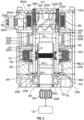
FIG. 2 shows aspects of the actuator ofFIG. 1 ; -
FIG. 3 shows a harmonic drive of the actuator, in which wave generator bearings are axially aligned with a flex spline; -
FIG. 4 shows the harmonic drive, in which the wave generator bearings are axially offset from the flex spline; -
FIG. 5 shows a motor shaft and a solenoid of the actuator; -
FIG. 6A shows the actuator in a housing in a first mode of operation; -
FIG. 6B shows the actuator in the first mode of operation, where the housing is not shown for clarity; -
FIG. 7A shows the actuator in the housing as the actuator transitions to a second mode of operation; -
FIG. 7B shows the actuator transitioning to the second mode of operation, where the housing is not shown for clarity; -
FIG. 8A shows the actuator in the housing in the second mode of operation; -
FIG. 8B shows the actuator in the second mode of operation, where the housing is not shown for clarity; and -
FIG. 9 shows an output shaft and retainer plate of the actuator. - Turning to
FIG. 1 , anaircraft 100 may have anengine 110 with amovable component 120 such as a blade or vane. Anactuator 130 may control the angulation of thecomponent 120. Theactuator 130 is controlled by a motor controller,motor 140, and reduction gearing. According to the embodiments, theactuator 130 is a failsafe electro-mechanical actuator. That is, should the motor controller,motor 140, or reduction gearing fail in flight, theactuator 130 rotates thecomponent 120 to a predetermined position so that flight may continue without disruption. - With reference to
FIG. 2 , theactuator 130 may include ahousing 150 that extends from afirst end 150A to asecond end 150B. Anelectrical connector 160 is located at thefirst end 150A to provide power to, for example,stator coils 170 fixedly supported within thehousing 150. - A
motor shaft 180, supported to rotate within thehousing 150, extends from afirst end 180A to asecond end 180B and has anintermediate section 180C therebetween. Themotor shaft 180 is oriented so that itsfirst end 180A is near thefirst end 150A of thehousing 150 and itssecond end 180B is near thesecond end 150B of thehousing 150. Themotor shaft 180 has outwardly facingrotor magnets 190, disposed about theintermediate section 180C and which, together with thestator coils 170, forms themotor 140. In operation, application of a current to thestator coils 170 results in rotation of themotor shaft 180 due to interaction of the fields created by the current in thestator coils 170 and therotor magnets 190. -
Roller bearings 200A, 200B are provided in thehousing 150 to support themotor shaft 180. As illustrated, theroller bearings 200A, 200B are arranged, near thefirst end 180A of themotor shaft 180 and thesecond end 180B of themotor shaft 180, to enable its rotation within thehousing 150. Themotor shaft 180 may move axially within thehousing 150 against theroller bearings 200A, 200B. - A
retainer plate 210 is supported at thefirst end 150A of thehousing 150. Acoil spring 220 extends from theretainer plate 210 to thefirst end 180A of themotor shaft 180 with a first thrust bearing 230A therebetween. Thecoil spring 220 urges themotor shaft 180 axially toward thesecond end 150B of thehousing 150. Asupport platform 240 is fixed within thehousing 150, near thesecond end 150B of thehousing 150, and axially supports themotor shaft 180 at that end of thehousing 150 during a first mode of operation of the actuator 130 (discussed below).. A second thrust bearing 230B arranged is between thesecond end 180B of themotor shaft 180 and thesupport platform 240. Ball bearings (or lower ball bearings) 200C are between thesupport platform 240 and the second end 150C of thehousing 150. - An
output shaft 250 is rotationally supported within thehousing 150 and is surrounded by themotor shaft 180 at least partly along its length. Theoutput shaft 250 has afirst end 250A (or head) and asecond end 250B (or output end) and anintermediate section 250C therebetween. Themotor shaft 180 is shorter than theoutput shaft 250. As shown, themotor shaft 180 is arranged around theoutput shaft 250 so thefirst end 250A of theoutput shaft 250 extends past thefirst end 180A of themotor shaft 180 and thesecond end 250B of theoutput shaft 250 extends past thesecond end 180B of themotor shaft 180. Thefirst end 250A of theoutput shaft 250 is within thehousing 150 and near thefirst end 150A of thehousing 150, such that theretainer plate 210 is at thefirst end 250A of theoutput shaft 250. Thesecond end 250B of theoutput shaft 250 extends out of thesecond end 150B of thehousing 150 to connect with themovable component 120. Thesupport platform 240 surrounds theoutput shaft 250 and is located near thesecond end 250B of theoutput shaft 250. Aretainer clip 260 andball bearings 200C are located near thesecond end 250B of theoutput shaft 250 at thesecond end 150B of thehousing 150. - The
first end 250A of theoutput shaft 250 has a first outer diameter DO1. Thesecond end 250B of theoutput shaft 250 has a second outer diameter DO2. Theintermediate section 250C of theoutput shaft 250 has a third outer diameter DOS. The first outer diameter DO1 is larger than the second and third outer diameters DO2, DOS. Themotor shaft 180 has an inner diameter DI that is sized for a slip fit against thefirst end 250A of theoutput shaft 250. A radial gap R is defined between themotor shaft 180 and theintermediate section 250C of theoutput shaft 250. Aharmonic drive 270 is sized to fit within the radial gap R. - As shown in
FIG. 3 , afirst portion 180D of theintermediate section 180C ofmotor shaft 180 and afirst portion 250D of theintermediate section 250C of theoutput shaft 250 are shown. Therotor magnets 190 are located at thefirst portion 180D of themotor shaft 180. An inwardly facing wave generator profile (or shape) 290 is formed onto themotor shaft 180 at least along itsfirst portion 180D. That is, thewave generator profile 290 is cut directly into the inner surface of themotor shaft 180 in the region shown betweengrooves 310 formed in themotor shaft 180 on either side of the wave generator profile. As a result, themotor shaft 180 may be considered a wave generator. -
Bearings 200E are disposed against thefirst portion 180D of themotor shaft 180. There is a bearing race on the inner wave generator shape,wave generator bearings 290 inside the bearing race and another bearing race inside the bearings. Thebearings 200E are surrounded axially within a bearingcage 202. Thebearings 200E are secured to themotor shaft 180, e.g., bearing retainer rings 300 are secured to thegrooves 310 that are formed in themotor shaft 180. Athrust washer 320 holds the bearings in place axially. An outwardly facingcircular spline 330 is disposed on afirst portion 250D of theoutput shaft 250. Aflex spline 340 is disposed against thecircular spline 330 and is acted upon by thewave generator profile 290 via thebearings 200E. Thegroves 310 in the motor shaft and therings 300, hold the wave generator bearing components axially to the motor shaft. When the motor shaft is pulled towards thefirst end 150A, the grooves and retaining rings force the wave generator bearings to move with the motor shaft. - As shown in
FIG. 2 , theflex spline 340 may be formed onto afirst portion 350D of aflex spline shaft 350 that extends from afirst end 350A to a second end 350B. The second end 350B of theflex spline shaft 350 forms the support platform 240 (FIG. 2 ) and thefirst end 350A of theflex spline shaft 350 is located between theflex spline 340 and thefirst end 250A of theoutput shaft 250. Thus, theflex spline 340 is axially fixed within thehousing 150 and relative to theoutput shaft 250. - The
support platform 240 also is mechanically fixed to thehousing 150 with fasteners and or pins. Apin hole 343 for receiving a pin is shown onFIG. 2 . This configuration fixes the flex-spline rotationally to thehousing 150. With the housing being fixed to ground, this grounds the flex spline to react rotational torques. - As shown in
FIG. 3 , when thesecond end 180B of themotor shaft 180 is located adjacent to thesupport platform 240, i.e., against the second thrust bearing 230B, thefirst portions motor shaft 180 andoutput shaft 250 are axially aligned and theharmonic drive 270 transfers rotational energy from themotor shaft 180 to theoutput shaft 250. As shown inFIG. 4 , when themotor shaft 180 moves toward thefirst end 150A of thehousing 150, thefirst portions motor shaft 180 andoutput shaft 250 are axially space apart and theharmonic drive 270 does not transfer rotational energy from themotor shaft 180 to theoutput shaft 250. - The
first portions output shaft 250 andmotor shaft 180 are axially shorter than and an axial range of motion for themotor shaft 180 in a second mode of operation (discussed below). With this configuration, theharmonic drive 270 is disengaged when themotor shaft 180 moves axially as the actuator 130 changes operational modes. - Turning back to
FIG. 2 , thefirst end 250A of theoutput shaft 250 extends from afirst end 252A, located at theintermediate section 250C of theoutput shaft 250, and asecond end 252B, located at an axialouter surface 254 of theoutput shaft 250. Between the axial ends 252A, 252B of thefirst end 250A, thefirst end 250A has an axial outer portion 250A1 and an axial inner portion 250A2. The outer portion 250A1 has outwardly facinghelical grooves 360 and the inner portion 250A2 has lead-ingrooves 370 that are continuous with thehelical grooves 360. Thehelical grooves 360 extend from the lead-ingrooves 370 to helical groove ends 360A that are spaced apart from the axialouter surface 254 of theoutput shaft 250. That is, thehelical grooves 360 do not reach the axialouter surface 254 of theoutput shaft 250. The inner portion 250A2 tapers radially inwardly.Ball bearings 200D are embedded in themotor shaft 180, near thefirst end 180A of themotor shaft 180, so that when thesecond end 180B of themotor shaft 180 is adjacent to thesupport platform 240, i.e., against the second thrust bearing 230B, theball bearings 200D are axially aligned with the inner portion 250A2 of thefirst end 250A of theoutput shaft 250 and do not engage theoutput shaft 250. Theball bearings 200D engage the groves in theoutput shaft 250 when themotor shaft 180 moves toward thefirst end 150A of thehousing 150. - A
solenoid 380 surrounds, and is axially aligned with, thefirst end 250A of theoutput shaft 250. Thesolenoid 380 is axially and rotationally fixed in thehousing 150. As shown inFIG. 5 , thesolenoid 380 has a frame or shell 382 withcoil windings 384 wrapped around thesolenoid shell 382. Thesolenoid shell 382 defines an inner surface, orshaft 380A, formed with axially extendinggrooves 400. Thesolenoid 380 extends from a first end 380A1, that is axially aligned with an intersection between the lead-ingrooves 370 and thehelical grooves 360 of theoutput shaft 250, to a second end 380A2, that is at or near the axialouter surface 254 of theoutput shaft 250. That is, thesolenoid 380 extends closer to the axialouter surface 254 of theoutput shaft 250 than the helical groove ends 360A. - In the second mode of operation (discussed below), application of a current to the solenoid coils 384 rather than the motor coils 170 results in drawing of the
motor shaft 180 into thesolenoid shaft 380A due to interaction of the fields created by the current in the solenoid coils 384 and the ferromagnetic material of themotor shaft 190. Thefirst end 180A of themotor shaft 180 has radially outwardlyprojections 390. When thefirst end 180A of themotor shaft 180 moves axially into thesolenoid shaft 380A, theprojections 390 move into thegrooves 400 to rotationally fix themotor shaft 180 relative to thesolenoid 380. - The axial extension of the
flex spline 340 towardsfirst end 150A is such that when the second mode is established, the wave generator bearing 200E remains within (e.g., is constrained from leaving) the bore of theflex spline 340 but is spaced apart (e.g., not over) the splined portion of theflex spline 340. This configuration keeps thebearing 200E captured along the motor shaft. - Turning to
FIGS. 6-8 , theactuator 130 has two modes of operation, including the first or normal mode, and the second or failsafe mode. The second mode occurs when themotor 140 fails to act as expected. During the first mode (FIGS. 6A-6B ), thesolenoid 380 is not powered, themotor shaft 180 is adjacent to thesupport platform 240, and theharmonic drive 270 is engaged. During this mode, theball bearings 200D that are embedded in themotor shaft 180 do not engage theoutput shaft 250
During the second mode of operation, thesolenoid 380 is powered. Themotor shaft 180 is initially drawn toward thefirst end 150A of thehousing 150, as the electromagnetic force generated by the solenoid 380 (discussed above) overpowers the spring force from thespring 220 and enters the solenoid 380 (FIGS.7A-7B ). At this time, theharmonic drive 270 is disengaged, themotor shaft 180 is prevented from rotation in thehousing 150, and theball bearings 200D that are embedded in themotor shaft 180 engage the lead-ingrooves 370 and are guided toward thehelical grooves 360 in theoutput shaft 250. As the second mode continues (FIGS. 8A-8B ), theoutput shaft 250 turns due to advancement of theball bearings 200D that are embedded in themotor shaft 180 within thehelical grooves 360. During this time, themovable component 120 is pivoted to the failsafe position. As thehelical grooves 360 do not reach the axialouter surface 254 of theoutput shaft 250, theball bearings 200D are unable to roll out of thefirst end 250A of theoutput shaft 250. - Turning to
FIG. 9 , thefirst end 250A of theoutput shaft 250 includes axially extendingbosses 410 and theretainer plate 210 includes axially extending rotation limiter projections (or plate bosses) 395. During the second mode of operation, thebosses 410 engage theplate bosses 395 to limit rotation of theoutput shaft 250 while theball bearings 200D are moving toward the outer ends 360A of thehelical grooves 360. This limits rotation of themovable component 120. That is, thebosses output shaft 250 and theretainer plate 210 are constrained by the disclosed configuration from moving axially relative to each other. However theoutput shaft bosses 410 rotate normally withing theplate bosses 395 on the retainer plate and, at failure, the balls, helical grooves combination force theoutput shaft bosses 410 against theretainer plate bosses 395 and the rotation stops when they are forced together
Accordingly, the disclosed embodiments provides a system and method of independently isolating a failure and moving the actuator output to an end of stroke position, holding the actuator in that position. - The terminology used herein is for the purpose of describing particular embodiments only and is not intended to be limiting of the present disclosure. As used herein, the singular forms "a", "an" and "the" are intended to include the plural forms as well, unless the context clearly indicates otherwise. It will be further understood that the terms "comprises" and/or "comprising," when used in this specification, specify the presence of stated features, integers, steps, operations, elements, and/or components, but do not preclude the presence or addition of one or more other features, integers, steps, operations, element components, and/or groups thereof.
- Those of skill in the art will appreciate that various example embodiments are shown and described herein, each having certain features in the particular embodiments, but the present disclosure is not thus limited. Rather, the present disclosure can be modified to incorporate any number of variations, alterations, substitutions, combinations, sub-combinations, or equivalent arrangements not heretofore described, but which are commensurate with the scope of the present disclosure. Additionally, while various embodiments of the present disclosure have been described, it is to be understood that aspects of the present disclosure may include only some of the described embodiments. Accordingly, the present disclosure is not to be seen as limited by the foregoing description, but is only limited by the scope of the appended claims.
Claims (15)
- A failsafe electro-mechanical actuator (130) for moving a component (120) within an aircraft (100), the actuator comprising:an output shaft (250) having a first end (250A) and a second end (250B) spaced apart from each other along a shaft axis, wherein the second end couples with the component (120), and outwardly facing helical grooves (360) formed along the first end; anda motor shaft (180) surrounding the output shaft;a harmonic drive (270) between the motor shaft (180) and the output shaft (250) that transfers motion from the motor shaft to the output shaft in a first mode of operation;ball bearings (200D) seated at the first end (180A) of the motor shaft (180) such that the ball bearings (200D) project inwardly from the motor shaft;wherein,in the first mode of operation: the ball bearings (200D) are disengaged from the output shaft (250) so that the output shaft rotates with the motor shaft, andin a second mode of operation, the motor shaft (180) axially moves toward the first end (250A) of the output shaft (250); the motor shaft is rotationally fixed; and the ball bearings (200D) engage the helical grooves (360) in the output shaft, whereby the output shaft rotates.
- The actuator of claim 1, wherein:
the motor shaft (180) has a first end (180A) and a second end (180B) spaced apart from each other along the shaft axis, wherein the first end (250A) of the output shaft (250) extends past the first end of the motor shaft and the second end (250B) of the output shaft extends past the second end of the motor shaft. - The actuator of claim 2, wherein:the output shaft (250) includes an intermediate section (250C) between the first end (250A) and the second end (250B) of the output shaft;the motor shaft (180) has an intermediate section (180C) between the first end (180A) and the second end (180B) of the motor shaft,the harmonic drive (270) includes:an inwardly facing wave generator profile (290) formed onto a first portion (180C) of the intermediate section (180D) of the motor shaft,bearings (200E) disposed against the wave generator profile that are axially fixed against the motor shaft;an outwardly facing circular spline (330) disposed on a first portion (250D) of the output shaft; anda flex spline (340) disposed against the circular spline (330) that is axially fixed against the output shaft,whereinin the first mode, the first portion of the motor and output shafts are axially aligned with each other, andin the second mode, the first portion of the motor and output shafts are axially offset from each other.
- The actuator of claim 3, wherein:
in the second mode, the motor shaft (180) moves axially by a predetermined distance, and the first portions (250D) of the output shaft (250) and the motor shaft (180) are axially shorter than the predetermined distance. - The actuator of claim 4, wherein:along the output shaft (250): the first end (250A) has a first outer diameter; the second end (250B) has a second outer diameter; and the intermediate section (250C) has a third outer diameter, wherein the first outer diameter is larger than the second and third outer diameters, andwhereby a radial gap (R) is defined between the motor shaft and the intermediate section of the output shaft, and the harmonic drive is sized to fit within the radial gap.
- The actuator of claims or 5, further comprising:
the motor shaft (180) has outwardly facing rotor magnets (190) located at the first portion (250D) of the motor shaft. - The actuator of claim 6, further comprising:a solenoid (380) that surrounds, and is axially aligned with, the first end (250A) of the output shaft (250) ,wherein the solenoid (380) is rotationally fixed, and in the second mode, the solenoid is activated to move the motor shaft (180) toward the first end of the output shaft (250).
- The actuator of claim 7, wherein the first end (180A) of the motor shaft (180) has radially outwardly facing projections (390); and
the solenoid (380) defines an inner surface formed with axially extending grooves (400), and in the second mode, the projections move into the grooves to rotationally fix the motor shaft. - The actuator of claim 8, further comprising:a support platform (240) surrounding the output shaft (250) and being located near the second end (250B) of the output shaft,wherein when the second end of the motor shaft is positioned adjacent to the support platform, the first portions of the motor and output shafts are axially aligned.
- The actuator of claim 9, further comprising:
a flex spline shaft (350) that extends from a first end (350A) to a second end (350B), wherein the second end defines the support platform (240), and the first end is located intermediate the flex spline (340) and the first end of the motor shaft, and wherein the flex spline is defined at a first portion of the flex spline shaft. - The actuator of claim 9 or 10, including:a retainer plate (210) located at the first end (250A) of the output shaft (250);a coil spring (220) disposed between the retainer plate (210) and the motor shaft (180), to urge the motor shaft toward the support platform; optionallywherein:the first end (250A) of the output shaft (250) includes axially extending bosses (410) and the retainer plate (210) includes axially extending rotation limiter projections (395), andin the second mode, the bosses engage the projections (390) to limit rotation of the output shaft.
- The actuator of claim 11, further comprising:a first thrust (230A) bearing axially between the coil spring (220) and the motor shaft (180); optionallyfurther comprising:
a second thrust bearing (230B) axially between the motor shaft (180) and the support platform (240). - The actuator of claim 11 or 12, further comprising:a housing (150) that surrounds the motor shaft (180), the solenoid (380), the support platform (240) and to which the retainer plate (210) is secured; optionallyfurther comprising:
roller bearings (200A, 200B) disposed within the housing (150), the roller bearings supporting the motor shaft (180), the roller bearings being located:axially between the first portion (180D) of the motor shaft and the first end (180A) of the motor shaft; andaxially between the first portion of the motor shaft and the second end of the motor shaft (180B). - The actuator of claim 12, further comprising:lower ball bearings (200C) disposed within the housing (150), wherein the lower ball bearings support the output shaft (250) and are located axially between the support platform (240) and the second end of the output shaft, and/orfurther comprising:stator windings supported in the housing,wherein the stator windings are positioned such that the stator windings are axially aligned with the rotor magnets (190) when the first portions of the motor shaft and the output shaft are axially aligned.
- An aircraft further comprising:a rotatable component (120); andthe actuator (130) of any preceding claim connected to the component and configured to rotate the component; optionallywherein the component is a control surface or a stator vane within an engine of the aircraft.
Applications Claiming Priority (1)
| Application Number | Priority Date | Filing Date | Title |
|---|---|---|---|
| US17/987,366 US12179911B2 (en) | 2022-11-15 | 2022-11-15 | Failsafe electro-mechanical actuator |
Publications (2)
| Publication Number | Publication Date |
|---|---|
| EP4371873A1 true EP4371873A1 (en) | 2024-05-22 |
| EP4371873B1 EP4371873B1 (en) | 2026-03-11 |
Family
ID=88833712
Family Applications (1)
| Application Number | Title | Priority Date | Filing Date |
|---|---|---|---|
| EP23209866.5A Active EP4371873B1 (en) | 2022-11-15 | 2023-11-14 | Failsafe electro-mechanical actuator |
Country Status (3)
| Country | Link |
|---|---|
| US (1) | US12179911B2 (en) |
| EP (1) | EP4371873B1 (en) |
| CA (1) | CA3218770A1 (en) |
Citations (4)
| Publication number | Priority date | Publication date | Assignee | Title |
|---|---|---|---|---|
| US6012347A (en) * | 1996-11-05 | 2000-01-11 | Toyota Jidosha Kabushiki Kaisha | Power steering apparatus |
| US20150184700A1 (en) * | 2013-11-21 | 2015-07-02 | Hamilton Sundstrand Corporation | Drive assembly with selective disconnect |
| US9371899B2 (en) * | 2014-05-27 | 2016-06-21 | Hamilton Sundstrand Corporation | Harmonic drive assembly with selective disconnect and reconnect |
| US20180038468A1 (en) * | 2016-08-05 | 2018-02-08 | Hamilton Sundstrand Corporation | Joined flex spline for compound harmonic drive |
Family Cites Families (1)
| Publication number | Priority date | Publication date | Assignee | Title |
|---|---|---|---|---|
| US9353804B2 (en) | 2014-07-08 | 2016-05-31 | Hamilton Sundstrand Corporation | Harmonic drive assembly with selective disconnect and method |
-
2022
- 2022-11-15 US US17/987,366 patent/US12179911B2/en active Active
-
2023
- 2023-11-03 CA CA3218770A patent/CA3218770A1/en active Pending
- 2023-11-14 EP EP23209866.5A patent/EP4371873B1/en active Active
Patent Citations (4)
| Publication number | Priority date | Publication date | Assignee | Title |
|---|---|---|---|---|
| US6012347A (en) * | 1996-11-05 | 2000-01-11 | Toyota Jidosha Kabushiki Kaisha | Power steering apparatus |
| US20150184700A1 (en) * | 2013-11-21 | 2015-07-02 | Hamilton Sundstrand Corporation | Drive assembly with selective disconnect |
| US9371899B2 (en) * | 2014-05-27 | 2016-06-21 | Hamilton Sundstrand Corporation | Harmonic drive assembly with selective disconnect and reconnect |
| US20180038468A1 (en) * | 2016-08-05 | 2018-02-08 | Hamilton Sundstrand Corporation | Joined flex spline for compound harmonic drive |
Also Published As
| Publication number | Publication date |
|---|---|
| US20240158069A1 (en) | 2024-05-16 |
| EP4371873B1 (en) | 2026-03-11 |
| US12179911B2 (en) | 2024-12-31 |
| CA3218770A1 (en) | 2024-05-15 |
Similar Documents
| Publication | Publication Date | Title |
|---|---|---|
| US9664050B2 (en) | Bearings for a turbomachine having an electric motor | |
| EP3776819B1 (en) | A generator having a disconnect mechanism | |
| CN104648658B (en) | Drive assembly with selective break part | |
| US8512185B2 (en) | Switchable drive pulley with electrically actuated friction disc torque transfer mechanism | |
| EP2119876A2 (en) | Supporting gas turbine rotor during unbalances | |
| US20060071190A1 (en) | Linear valve actuator | |
| EP3021465B1 (en) | Resettable electro-mechanically actuated connection unit for generators | |
| CN110291282A (en) | Air Turbine Starter with Separator | |
| EP4371873B1 (en) | Failsafe electro-mechanical actuator | |
| US6260667B1 (en) | Rotor containment brake | |
| US10941842B2 (en) | Resettable electro-mechanical cam actuated shaft disconnect for generators | |
| EP2098740B1 (en) | Drive disconnect device | |
| EP0299266B1 (en) | Torque transmitting member, combustion turbine engine including same, and method of use | |
| US12451760B2 (en) | Integrated drive gear motor assembly for a vehicle | |
| CN114337186B (en) | Permanent magnet eddy current speed regulating device | |
| US20030006119A1 (en) | Screw actuator | |
| US12021435B2 (en) | Disconnect bearing and input seal for a variable frequency starter generator | |
| KR20180107098A (en) | Electromagnetic brake for power transmission assembly | |
| US12259031B2 (en) | Balanced harmonic drive with output shaft disconnect | |
| EP3783241B1 (en) | Low drag torque limiter for electric tras | |
| BR102023022379A2 (en) | FAIL-SAFE ELECTROMECHANICAL ACTUATOR, E, AIRCRAFT | |
| EP2017489A2 (en) | Drive transfer device | |
| US5893440A (en) | Flexible mounting for a clutch | |
| US6710478B1 (en) | Centrifugal actuator | |
| EP4261425B1 (en) | High ramp angle disconnect shaft |
Legal Events
| Date | Code | Title | Description |
|---|---|---|---|
| PUAI | Public reference made under article 153(3) epc to a published international application that has entered the european phase |
Free format text: ORIGINAL CODE: 0009012 |
|
| STAA | Information on the status of an ep patent application or granted ep patent |
Free format text: STATUS: THE APPLICATION HAS BEEN PUBLISHED |
|
| AK | Designated contracting states |
Kind code of ref document: A1 Designated state(s): AL AT BE BG CH CY CZ DE DK EE ES FI FR GB GR HR HU IE IS IT LI LT LU LV MC ME MK MT NL NO PL PT RO RS SE SI SK SM TR |
|
| STAA | Information on the status of an ep patent application or granted ep patent |
Free format text: STATUS: REQUEST FOR EXAMINATION WAS MADE |
|
| 17P | Request for examination filed |
Effective date: 20241121 |
|
| RBV | Designated contracting states (corrected) |
Designated state(s): AL AT BE BG CH CY CZ DE DK EE ES FI FR GB GR HR HU IE IS IT LI LT LU LV MC ME MK MT NL NO PL PT RO RS SE SI SK SM TR |
|
| GRAP | Despatch of communication of intention to grant a patent |
Free format text: ORIGINAL CODE: EPIDOSNIGR1 |
|
| STAA | Information on the status of an ep patent application or granted ep patent |
Free format text: STATUS: GRANT OF PATENT IS INTENDED |
|
| INTG | Intention to grant announced |
Effective date: 20251008 |
|
| GRAS | Grant fee paid |
Free format text: ORIGINAL CODE: EPIDOSNIGR3 |
|
| GRAA | (expected) grant |
Free format text: ORIGINAL CODE: 0009210 |
|
| STAA | Information on the status of an ep patent application or granted ep patent |
Free format text: STATUS: THE PATENT HAS BEEN GRANTED |
|
| AK | Designated contracting states |
Kind code of ref document: B1 Designated state(s): AL AT BE BG CH CY CZ DE DK EE ES FI FR GB GR HR HU IE IS IT LI LT LU LV MC ME MK MT NL NO PL PT RO RS SE SI SK SM TR |
|
| REG | Reference to a national code |
Ref country code: CH Ref legal event code: F10 Free format text: ST27 STATUS EVENT CODE: U-0-0-F10-F00 (AS PROVIDED BY THE NATIONAL OFFICE) Effective date: 20260311 Ref country code: GB Ref legal event code: FG4D |
|
| REG | Reference to a national code |
Ref country code: DE Ref legal event code: R096 Ref document number: 602023013299 Country of ref document: DE |
|
| REG | Reference to a national code |
Ref country code: IE Ref legal event code: FG4D |
|
| PG25 | Lapsed in a contracting state [announced via postgrant information from national office to epo] |
Ref country code: RS Free format text: LAPSE BECAUSE OF FAILURE TO SUBMIT A TRANSLATION OF THE DESCRIPTION OR TO PAY THE FEE WITHIN THE PRESCRIBED TIME-LIMIT Effective date: 20260611 |
|
| PG25 | Lapsed in a contracting state [announced via postgrant information from national office to epo] |
Ref country code: ES Free format text: LAPSE BECAUSE OF FAILURE TO SUBMIT A TRANSLATION OF THE DESCRIPTION OR TO PAY THE FEE WITHIN THE PRESCRIBED TIME-LIMIT Effective date: 20260311 |
|
| PG25 | Lapsed in a contracting state [announced via postgrant information from national office to epo] |
Ref country code: GR Free format text: LAPSE BECAUSE OF FAILURE TO SUBMIT A TRANSLATION OF THE DESCRIPTION OR TO PAY THE FEE WITHIN THE PRESCRIBED TIME-LIMIT Effective date: 20260612 |
|
| REG | Reference to a national code |
Ref country code: LT Ref legal event code: MG9D |
|
| PG25 | Lapsed in a contracting state [announced via postgrant information from national office to epo] |
Ref country code: LT Free format text: LAPSE BECAUSE OF FAILURE TO SUBMIT A TRANSLATION OF THE DESCRIPTION OR TO PAY THE FEE WITHIN THE PRESCRIBED TIME-LIMIT Effective date: 20260311 |
|
| PG25 | Lapsed in a contracting state [announced via postgrant information from national office to epo] |
Ref country code: NO Free format text: LAPSE BECAUSE OF FAILURE TO SUBMIT A TRANSLATION OF THE DESCRIPTION OR TO PAY THE FEE WITHIN THE PRESCRIBED TIME-LIMIT Effective date: 20260611 |
|
| PG25 | Lapsed in a contracting state [announced via postgrant information from national office to epo] |
Ref country code: FI Free format text: LAPSE BECAUSE OF FAILURE TO SUBMIT A TRANSLATION OF THE DESCRIPTION OR TO PAY THE FEE WITHIN THE PRESCRIBED TIME-LIMIT Effective date: 20260311 Ref country code: SE Free format text: LAPSE BECAUSE OF FAILURE TO SUBMIT A TRANSLATION OF THE DESCRIPTION OR TO PAY THE FEE WITHIN THE PRESCRIBED TIME-LIMIT Effective date: 20260311 |
|
| REG | Reference to a national code |
Ref country code: NL Ref legal event code: MP Effective date: 20260311 |
|
| PG25 | Lapsed in a contracting state [announced via postgrant information from national office to epo] |
Ref country code: HR Free format text: LAPSE BECAUSE OF FAILURE TO SUBMIT A TRANSLATION OF THE DESCRIPTION OR TO PAY THE FEE WITHIN THE PRESCRIBED TIME-LIMIT Effective date: 20260311 |
|
| PG25 | Lapsed in a contracting state [announced via postgrant information from national office to epo] |
Ref country code: LV Free format text: LAPSE BECAUSE OF FAILURE TO SUBMIT A TRANSLATION OF THE DESCRIPTION OR TO PAY THE FEE WITHIN THE PRESCRIBED TIME-LIMIT Effective date: 20260311 |
|
| PG25 | Lapsed in a contracting state [announced via postgrant information from national office to epo] |
Ref country code: BG Free format text: LAPSE BECAUSE OF FAILURE TO SUBMIT A TRANSLATION OF THE DESCRIPTION OR TO PAY THE FEE WITHIN THE PRESCRIBED TIME-LIMIT Effective date: 20260311 |