EP4371816A1 - System including seat pan assembly - Google Patents
System including seat pan assembly Download PDFInfo
- Publication number
- EP4371816A1 EP4371816A1 EP23210030.5A EP23210030A EP4371816A1 EP 4371816 A1 EP4371816 A1 EP 4371816A1 EP 23210030 A EP23210030 A EP 23210030A EP 4371816 A1 EP4371816 A1 EP 4371816A1
- Authority
- EP
- European Patent Office
- Prior art keywords
- aft
- link
- fore
- driver
- driven
- Prior art date
- Legal status (The legal status is an assumption and is not a legal conclusion. Google has not performed a legal analysis and makes no representation as to the accuracy of the status listed.)
- Pending
Links
- 230000033001 locomotion Effects 0.000 claims description 29
- 239000006260 foam Substances 0.000 claims description 24
- 230000001419 dependent effect Effects 0.000 claims 2
- 230000000712 assembly Effects 0.000 description 5
- 238000000429 assembly Methods 0.000 description 5
- 238000000034 method Methods 0.000 description 5
- 239000004677 Nylon Substances 0.000 description 3
- 239000002184 metal Substances 0.000 description 3
- 229920001778 nylon Polymers 0.000 description 3
- 230000008901 benefit Effects 0.000 description 2
- 230000003321 amplification Effects 0.000 description 1
- 238000013459 approach Methods 0.000 description 1
- 230000005540 biological transmission Effects 0.000 description 1
- 238000010276 construction Methods 0.000 description 1
- 238000013016 damping Methods 0.000 description 1
- 230000003111 delayed effect Effects 0.000 description 1
- 230000009977 dual effect Effects 0.000 description 1
- 239000004744 fabric Substances 0.000 description 1
- 238000003199 nucleic acid amplification method Methods 0.000 description 1
- 230000001105 regulatory effect Effects 0.000 description 1
- 238000004904 shortening Methods 0.000 description 1
Images












Classifications
-
- B—PERFORMING OPERATIONS; TRANSPORTING
- B64—AIRCRAFT; AVIATION; COSMONAUTICS
- B64D—EQUIPMENT FOR FITTING IN OR TO AIRCRAFT; FLIGHT SUITS; PARACHUTES; ARRANGEMENT OR MOUNTING OF POWER PLANTS OR PROPULSION TRANSMISSIONS IN AIRCRAFT
- B64D11/00—Passenger or crew accommodation; Flight-deck installations not otherwise provided for
- B64D11/06—Arrangements of seats, or adaptations or details specially adapted for aircraft seats
- B64D11/0639—Arrangements of seats, or adaptations or details specially adapted for aircraft seats with features for adjustment or converting of seats
-
- B—PERFORMING OPERATIONS; TRANSPORTING
- B60—VEHICLES IN GENERAL
- B60N—SEATS SPECIALLY ADAPTED FOR VEHICLES; VEHICLE PASSENGER ACCOMMODATION NOT OTHERWISE PROVIDED FOR
- B60N2/00—Seats specially adapted for vehicles; Arrangement or mounting of seats in vehicles
- B60N2/02—Seats specially adapted for vehicles; Arrangement or mounting of seats in vehicles the seat or part thereof being movable, e.g. adjustable
- B60N2/0224—Non-manual adjustments, e.g. with electrical operation
- B60N2/0244—Non-manual adjustments, e.g. with electrical operation with logic circuits
- B60N2/0256—Arrangements for facilitating the occupant to get in or out of the vehicle, e.g. stowing a seat forward
-
- B—PERFORMING OPERATIONS; TRANSPORTING
- B60—VEHICLES IN GENERAL
- B60N—SEATS SPECIALLY ADAPTED FOR VEHICLES; VEHICLE PASSENGER ACCOMMODATION NOT OTHERWISE PROVIDED FOR
- B60N2/00—Seats specially adapted for vehicles; Arrangement or mounting of seats in vehicles
- B60N2/02—Seats specially adapted for vehicles; Arrangement or mounting of seats in vehicles the seat or part thereof being movable, e.g. adjustable
- B60N2/0284—Adjustable seat-cushion length
-
- B—PERFORMING OPERATIONS; TRANSPORTING
- B60—VEHICLES IN GENERAL
- B60N—SEATS SPECIALLY ADAPTED FOR VEHICLES; VEHICLE PASSENGER ACCOMMODATION NOT OTHERWISE PROVIDED FOR
- B60N2/00—Seats specially adapted for vehicles; Arrangement or mounting of seats in vehicles
- B60N2/24—Seats specially adapted for vehicles; Arrangement or mounting of seats in vehicles for particular purposes or particular vehicles
- B60N2/30—Non-dismountable or dismountable seats storable in a non-use position, e.g. foldable spare seats
- B60N2/3038—Cushion movements
- B60N2/3063—Cushion movements by composed movement
- B60N2/3065—Cushion movements by composed movement in a longitudinal-vertical plane
-
- B—PERFORMING OPERATIONS; TRANSPORTING
- B64—AIRCRAFT; AVIATION; COSMONAUTICS
- B64D—EQUIPMENT FOR FITTING IN OR TO AIRCRAFT; FLIGHT SUITS; PARACHUTES; ARRANGEMENT OR MOUNTING OF POWER PLANTS OR PROPULSION TRANSMISSIONS IN AIRCRAFT
- B64D11/00—Passenger or crew accommodation; Flight-deck installations not otherwise provided for
- B64D11/06—Arrangements of seats, or adaptations or details specially adapted for aircraft seats
- B64D11/0639—Arrangements of seats, or adaptations or details specially adapted for aircraft seats with features for adjustment or converting of seats
- B64D11/0643—Adjustable foot or leg rests
Definitions
- Type III overwing exit egress requirements drive the spacing of seats in aircraft. The most constraining requirements surround the egress path toward the exit.
- the system includes a seat pan assembly.
- the seat pan assembly may include a fixed link having a fore end and an aft end.
- the seat pan assembly may further include an aft driver link having an aft driver link fore end and an aft driver link aft end, wherein the aft driver link fore end is pivotably coupled to the aft end of the fixed link.
- the seat pan assembly may further include a fore driven link having a fore driven link fore end and a fore driven link aft end, wherein the fore driven link aft end is pivotably coupled to the fore end of the fixed link.
- the aft driver link aft end When a downward component force acts upon the aft driver link, the aft driver link aft end is configured to rotate about the aft end of the fixed link and cause the fore driven link fore end to rotate about the fore end of the fixed link such that the fore driven link fore end is configured to move at least partially in an upward direction and forward direction.
- a system in a further aspect, includes a seat pan assembly.
- the seat pan assembly may include an aft driver link having an aft driver link fore end and an aft driver link aft end.
- the seat pan assembly may include a fore driven link having a fore driven link fore end and a fore driven link aft end, wherein the fore driven link aft end is pivotably coupled to the aft driver link fore end.
- the aft driver link aft end When a downward component force acts upon the aft driver link, the aft driver link aft end is configured to rotate about the fore driven link aft end and cause the fore driven link fore end to rotate about the aft driver link fore end such that the fore driven link fore end is configured to move at least partially in an upward direction and forward direction.
- inventive concepts are not limited in their application to the details of construction and the arrangement of the components or steps or methodologies set forth in the following description or illustrated in the drawings.
- inventive concepts disclosed herein may be practiced without these specific details.
- well-known features may not be described in detail to avoid unnecessarily complicating the instant disclosure.
- inventive concepts disclosed herein are capable of other embodiments or of being practiced or carried out in various ways. Also, it is to be understood that the phraseology and terminology employed herein is for the purpose of description and should not be regarded as limiting.
- a letter following a reference numeral is intended to reference an embodiment of the feature or element that may be similar, but not necessarily identical, to a previously described element or feature bearing the same reference numeral (e.g., 1, 1a, 1b).
- reference numeral e.g. 1, 1a, 1b
- Such shorthand notations are used for purposes of convenience only, and should not be construed to limit the inventive concepts disclosed herein in any way unless expressly stated to the contrary.
- any reference to "one embodiment,” or “some embodiments” means that a particular element, feature, structure, or characteristic described in connection with the embodiment is included in at least one embodiment of the inventive concepts disclosed herein.
- the appearances of the phrase “in some embodiments” in various places in the specification are not necessarily all referring to the same embodiment, and embodiments of the inventive concepts disclosed may include one or more of the features expressly described or inherently present herein, or any combination of sub-combination of two or more such features, along with any other features which may not necessarily be expressly described or inherently present in the instant disclosure.
- embodiments of the inventive concepts disclosed herein are directed to a system including a seat pan assembly.
- Some embodiments offer a solution to maintain the overwing exit egress path when the aircraft seat is not occupied, such as during an emergency egress.
- a seat pan assembly may move between an occupied state to a more compressed unoccupied state so as to open a greater emergency egress path during an evacuation.
- the movement of the seat pan assembly may be damped and/or delayed to prevent movement of the seat pan assembly during a momentary seating position shift by a passenger.
- Some embodiments may provide an increased density (e.g., about 2-3" for a single overwing exit (OWE) and about 4-6" for dual OWE).
- the increased density may translate to increased profitability for the airline.
- FIGS. 1-3 side views of exemplary embodiments of a system 100 including a vehicle (e.g., aircraft 102, watercraft, automobile, train, etc.) including at least one emergency egress path 104 (e.g., at least one OWE emergency egress path) positioned between two rows of aircraft seats (e.g., standard aircraft seats 106A having standard aircraft seat base frames 108A and/or aircraft seats 106 having compact aircraft seat base frames 108 and seat pan assemblies 110, 110A (such as shown in FIGS. 4A-16 )) depicted according to the inventive concepts.
- a vehicle e.g., aircraft 102, watercraft, automobile, train, etc.
- at least one emergency egress path 104 e.g., at least one OWE emergency egress path
- aircraft seats e.g., standard aircraft seats 106A having standard aircraft seat base frames 108A and/or aircraft seats 106 having compact aircraft seat base frames 108 and seat pan assemblies 110, 110A (such as shown in FIGS. 4A
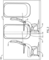
- FIG. 1 a side view of a currently implemented system 100 including an aircraft 102 including an emergency egress path 104 positioned between two rows of standard aircraft seats 106A having standard aircraft seat base frames 108A is depicted.
- FIG. 1 depicts a typical situation on a Type III overwing aircraft.
- Standard aircraft seats 106A are installed at minimum distance for density but large enough to allow regulatory minimum egress path 104 to the exit.
- a projected distance between the front most portion of the seat 106A at the exit and the aft most point of the seat forward of the exit must be maintained to ensure egress to the emergency exit.
- Some embodiments may include an aircraft seat(s) 106 having a seat pan assembly 110 (such as shown in FIGS. 4A-16 )) and a compact aircraft seat base frame 108, which is desired to create a supported seat surface when an occupant sits on the seat 106 while presenting with a reduced surface when the seat 106 is not occupied.
- a seat pan assembly 110 such as shown in FIGS. 4A-16
- a compact aircraft seat base frame 108 which is desired to create a supported seat surface when an occupant sits on the seat 106 while presenting with a reduced surface when the seat 106 is not occupied.
- FIG. 2 a side view of an exemplary embodiment of a system 100 including the aircraft 102 including at least one emergency egress path 104 (e.g., at least one OWE emergency egress path) positioned between two rows of aircraft seats (e.g., standard aircraft seats 106A having standard aircraft seat base frames 108A and aircraft seats 106 having compact aircraft seat base frames 108 and seat pan assemblies 110, 110A (such as shown in FIGS. 4A-16 )) depicted according to the inventive concepts.
- emergency egress path 104 e.g., at least one OWE emergency egress path
- aircraft seats e.g., standard aircraft seats 106A having standard aircraft seat base frames 108A and aircraft seats 106 having compact aircraft seat base frames 108 and seat pan assemblies 110, 110A (such as shown in FIGS. 4A-16 ) depicted according to the inventive concepts.
- Some embodiments include a new compressed and/or compact seat frame 108, which may be optimized for lower-weight, tight pitch seat assemblies which may be used for ultra high-density configurations suitable for use with some embodiments.
- the aircraft seat 106 may have higher interface loads as a result of a lower leg-pitch (e.g., front stud to aft fitting pivot).
- a reinforced floor structure in the overwing exit area may be used to allow for the higher loads in some applications.
- FIG. 3 a side view of an exemplary embodiment of a system 100 including the aircraft 102 including at least one emergency egress path 104 (e.g., at least one OWE emergency egress path) positioned between two rows of aircraft seats (e.g., standard aircraft seats 106A having standard aircraft seat base frames 108A and aircraft seats 106 having compact aircraft seat base frames 108 and seat pan assemblies 110, 110A (such as shown in FIGS. 4A-16 )) depicted according to the inventive concepts.
- aircraft seats e.g., standard aircraft seats 106A having standard aircraft seat base frames 108A and aircraft seats 106 having compact aircraft seat base frames 108 and seat pan assemblies 110, 110A (such as shown in FIGS. 4A-16 )
- FIG. 3 shows exemplary lengths of the aircraft seat 106's seat bottom (having the seat pan assembly 110A of FIGS. 4A-16 ) in a deployed state 110A and a stowed state 110B.
- some embodiments may include a seat pan assembly that can extend for comfort when occupied but may be reduced in length when unoccupied, such as during an emergency evacuation.
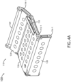
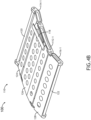
- FIGS. 4A-4B perspective views of an exemplary embodiment of the system 100 including the aircraft 102 including the aircraft seat 106 having compact aircraft seat base frames 108 and the seat pan assembly 110 in a stowed state (as shown in FIG. 4A ) and a deployed state (as shown in FIG. 4B ) are depicted according to the inventive concepts.
- the seat pan assembly 110 may include a fixed link 112-1 having a fore end and an aft end.
- the seat pan assembly 110 may include an aft driver link 114-1 having an aft driver link fore end and an aft driver link aft end, and the aft driver link fore end may be pivotably coupled to the aft end of the fixed link 112-1.
- the aft driver link aft end may be angled upward as compared to the rest of the aft driver link 114-1.
- the seat pan assembly 110 may include a fore driven link 116-1 having a fore driven link fore end and a fore driven link aft end, and the fore driven link aft end may be pivotably coupled to the fore end of the fixed link 112-1.
- the aft driver link aft end may be configured to rotate about the aft end of the fixed link 112-1 and cause the fore driven link fore end to rotate about the fore end of the fixed link 112-1 such that the fore driven link fore end is configured to move at least partially in an upward direction and forward direction, such as to a deployed seat pan state.
- the aft driver link aft end may be configured to rotate about the aft end of the fixed link 112-1 and cause the fore driven link fore end to rotate about the fore end of the fixed link 112-1 such that the fore driven link fore end is configured to move at least partially in a downward direction and aft direction, such as to a stowed state.
- the seat pan assembly 110 may further include a second fixed link (such as shown better in FIG. 6A ) having a second fore end and a second aft end.
- the seat pan assembly 110 may include a second aft driver link (such as shown better in FIG. 6A ) having a second aft driver link fore end and a second aft driver link aft end, and the second aft driver link fore end may be pivotably coupled to the second aft end of the second fixed link.
- the seat pan assembly 110 may include a second fore driven link (such as shown better in FIG.
- the seat pan assembly 110 may include an aft crossbar 120 connected between the second aft driver link aft end and the aft driver link aft end.
- the seat pan assembly 110 may include a fore crossbar 122 connected between the second fore driven link fore end and the fore driven link fore end.
- the second aft driver link aft end may be configured to rotate about the second aft end of the second fixed link and cause the second fore driven link fore end to rotate about the second fore end of the second fixed link such that the second fore driven link fore end is configured to move at least partially in an upward direction and forward direction, such as to the deployed state.
- the seat pan assembly 110 may further include a fore seat pan section 128 connected between the second fore driven link and the fore driven link 116-1.
- the seat pan assembly 110 may include a seat pan section 126 connected between the second fixed link and the fixed link 112-1.
- the seat pan assembly 110 may include an aft seat pan section 124 connected between the second aft driver link and the aft driver link 114-1.
- each of the fore seat pan section 128, the seat pan section 126, and the aft seat pan section 124 may be metal flex plan sections, which may provide sufficient support to a seated occupant and aid in the transfer of force needed to move seat pan assembly 110 from a deployed state to a stowed state, or vice versa.
- each of the fore seat pan section 128, the seat pan section 126, and the aft seat pan section 124 may be riveted onto one of the links on each side so as to make the seat pan sections integral with each section of the seat pan assembly 110.
- FIGS. 5A -5D side views of an exemplary embodiment of the seat pan assembly 110 in a stowed state (as shown in FIGS. 5A and 5B) and a deployed state (as shown in FIGS. 5C and 5D ) depicted according to the inventive concepts.
- a wire spring 130 may be coupled between the aft driver link 114-1 and the fixed link 112-1.
- the wire spring 130 may be guided through holes in the aft driver link 114-1 and the fixed link 112-1 to provide a default stowed state to the seat pan assembly 110 when an occupant is not sitting on the seat 106.
- through holes in the links 114-1, 112-1 may prevent the wire spring 130 from moving laterally.
- the wire spring 130 may be deformable (e.g., deflectable) in response to an occupant sitting in the seat 106.
- the wire spring 130 may provide the necessary force to position the seat pan assembly 110 in the stowed state when an occupant is not sitting in the seat 106.
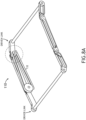
- FIGS. 6A-6E various views of an exemplary embodiment of the seat pan assembly 110 are depicted according to the inventive concepts.
- the seat pan assembly 110 may include a fixed link 112-1 having a fore end 112-1F and an aft end 112-1A.
- the seat pan assembly 110 may include an aft driver link 114-1 having an aft driver link fore end 114-1F and an aft driver link aft end 114-1A, and the aft driver link fore end 114-1F may be pivotably coupled to the aft end 112-1A of the fixed link 112-1.
- the aft driver link aft end 114-1A may be angled upward as compared to the rest of the aft driver link 114-1.
- the seat pan assembly 110 may include a fore driven link 116-1 having a fore driven link fore end 116-1F and a fore driven link aft end 116-1A, and the fore driven link aft end 116-1A may be pivotably coupled to the fore end 112-1F of the fixed link 112-1.
- the seat pan assembly 110 may further include a second fixed link 112-2 having a second fore end 112-2F and a second aft end 112-2A.
- the seat pan assembly 110 may include a second aft driver link 114-2 having a second aft driver link fore end 114-2F and a second aft driver link aft end 114-2A, and the second aft driver link fore end 114-2F may be pivotably coupled to the second aft end 112-2A of the second fixed link 112-2.
- the seat pan assembly 110 may include a second fore driven link 116-2 having a second fore driven link fore end 116-2F and a second fore driven link aft end 116-2A, and the second fore driven link aft end 116-2A may be pivotably coupled to the second fore end 112-2F of the second fixed link 112-2.
- the seat pan assembly 110 may include an aft crossbar 120 connected between the second aft driver link aft end 114-2A and the aft driver link aft end 114-1A.
- the seat pan assembly 110 may include a fore crossbar 122 connected between the second fore driven link fore end 116-2F and the fore driven link fore end 116-1F.
- the seat pan assembly 110 may further include a driver train 132 configured to transmit motion from the aft driver link 114-1 to the fore driven link 116-1.
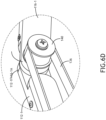
- the driver train 132 may include a driver timing pulley 134 (as shown in FIGS. 6B and 6C ), a driven pulley 140 (e.g., a driven timing pulley) (as shown in FIGS. 6D and 6E ), and a timing belt 136 (as shown in FIGS. 6A-6E ) installed around the driver timing pulley 134 and the driven pulley 140.
- the timing belt 136 may be used to connect the pulleys 134, 140 and transmit motion.
- the timing belt 136 may ensure no transmission losses occur between the driver timing pulley 134 and the driven pulley 140.
- the motion amplification may be achieved because of the smaller angle of rotation by choosing a suitable pulley diameter ratio between the driver timing pulley 134 and the driven pulley 140.
- the driver timing pulley 134 may have a greater diameter than the driven pulley 140.
- a first fastener 138 may extend through the driver timing pulley 134, the aft driver link fore end 114-1F, and the aft end 112-1A of the fixed link 112.
- a second fastener 142 may extend through the driven pulley 140, the fore driven link aft end 116-1A, and the fore end 112-1F of the fixed link 112.
- the driven pulley 140 may include multiple components (e.g., 140A, 140B).
- the driven pulley 140 may have a staggered gear including staggered gear components 140A, 140B such that an initial amount (e.g., an initial 5-8 degrees) of motion by the aft driver link 114-1 produces no motion in the fore driven link 116-1.
- the driven pulley 140 may have an annular gear including annular gear components 140A-1, 1408-1 (such as shown in FIG.
- the driver train 132 further includes the wire spring 130 coupled between the aft driver link 114-1 and the fixed link 112.
- the seat pan assembly 110 may further include a second driver train configured to transmit motion from the second aft driver link 114-2 to the fore driven link 116-2.
- the second driver train may function similarly to and have components similar to the driver train 132.
- FIGS. 7A-7C various views of an exemplary embodiment of driver train 132 of the seat pan assembly 110 are depicted according to the inventive concepts.
- FIG. 7A shows the seat pan assembly 110 including the driver train 132.
- FIG. 7B shows a cross-sectional view of a portion of the driver train 132.
- the first fastener 138 may extend through the driver timing pulley 134, the aft driver link 114-1, the fixed link 112, a first bearing 144, and a nut 146.
- FIG. 7C shows a cross-sectional view of a portion of the driver train 132.
- the second fastener 142 may extend through the driven pulley 140 (e.g., 140A and 140B or 140A-1 and 140B-1), the fore driven link 116-1, the fixed link 112-1, a second bearing 148, and a second nut 150.
- the driver train 132 and the fixed link 112-1 may be replaced with an annular gear system (e.g., as shown in FIG. 8D ) such that an initial amount (e.g., an initial 5-8 degrees) of motion by the aft driver link 114-1 produces no motion in the fore driven link 116-1.
- an initial amount e.g., an initial 5-8 degrees
- FIGS. 8A-8D various views of an exemplary embodiment of the driver train 132 of the seat pan assembly 110 are depicted according to the inventive concepts.
- FIG. 8A shows a perspective view of the driver train 132 of the seat pan assembly 110.
- FIG. 8B shows a perspective view of the driven pulley 140 (e.g., 140A and 140B or 140A-1 and 140B-1) of the driver train 132 of the seat pan assembly 110.
- the driven pulley 140 e.g., 140A and 140B or 140A-1 and 140B-1
- FIG. 8C shows a cut-away view of the driven pulley 140 comprised of the outer staggered gear component 140A and the inner staggered gear component 140B.
- an initial x degrees e.g., an initial 5-8 degrees
- motion by the aft driver link 114-1 produces no motion in the fore driven link 116-1 due to the outer staggered gear component 140A moving unimpeded before driving teeth of the inner staggered gear component 140B.
- FIG. 8D shows a cut-away view of the driven pulley 140 comprised of an annular gear including an outer annular gear component 140A-1 and an inner annular gear component 140B-1.
- an initial x degrees e.g., an initial 5-8 degrees
- the aft driver link 114-1 produces no motion in the fore driven link 116-1 due to the outer annular gear component 140A-1 having at least one more tooth than the the inner annular gear component 140B-1.
- FIGS. 9A-9B perspective views of an exemplary embodiment of the system 100 including the aircraft 102 including the aircraft seat 106 having compact aircraft seat base frames 108 and the seat pan assembly 110 in a deployed state depicted according to the inventive concepts.
- the seat pan assembly 110 may include a fixed link 112-1, an aft driver link 114-1, and a fore driven link 116-1.
- the seat pan assembly 110 may further include a second fixed link 112-2, a second aft driver link 114-2 and a second fore driven link 116-2 (such as shown better in FIG. 6A ).
- the seat pan assembly 110 may include an aft crossbar 120 connected between the second aft driver link aft end and the aft driver link aft end.
- the seat pan assembly 110 may include a fore crossbar 122 connected between the second fore driven link fore end and the fore driven link fore end.
- the seat pan assembly 110 may further include a fore seat pan section 128 connected between the second fore driven link 116-2 and the fore driven link 116-1.
- the seat pan assembly 110 may include a seat pan section 126 connected between the second fixed link 112-2 and the fixed link 112-1.
- the seat pan assembly 110 may include an aft seat pan section 124 connected between the second aft driver link 114-2 and the aft driver link 114-1.
- each of the fore seat pan section 128, the seat pan section 126, and the aft seat pan section 124 may be metal flex plan sections, which may provide sufficient support to a seated occupant and aid in the transfer of force needed to move seat pan assembly 110 from a deployed state to a stowed state, or vice versa.
- each of the fore seat pan section 128, the seat pan section 126, and the aft seat pan section 124 may be riveted onto one of the links on each side so as to make the seat pan sections integral with each section of the seat pan
- the seat pan section 126 may have a slot (e.g., between a grommet 152 and the fixed link 112-1) to accommodate a portion of the timing belt 136 passing from a top of the driver timing pulley 134 to below the seat pan section 126 to the driven pulley 140.
- the slot may have the grommet 152 around edges of the slot to protect the timing belt 136 from the edges of the slot.
- a shroud 118 may be attached to the fixed link 112-1 and may extend from the fixed link 112-1 to above the driver timing pulley 134 and above the timing belt 136.
- FIGS. 10A-10B perspective views of an exemplary embodiment of the system 100 including the aircraft 102 including the aircraft seat 106 having compact aircraft seat base frames 108 and the seat pan assembly 110 in a stowed state and a deployed state are depicted according to the inventive concepts.
- the aircraft seat 106 may include a fore foam seat section 158 installed above the fore seat pan section 128, a foam seat section 156 installed above the seat pan section 126, and an aft foam seat section 154 installed above the aft seat pan section 124.
- the fore foam seat section 158, the foam seat section 156, and the aft foam seat section 154 may be shaped such that the fore foam seat section 158, the foam seat section 156, and the aft foam seat section 154 do not impede motion of the aft driver link 114-1 and the fore driven link 116-1.
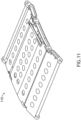
- FIG. 11 a perspective views of an exemplary embodiment of the seat pan assembly 110 in a deployed state is depicted according to the inventive concepts.
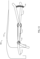
- FIG. 12 a side view of an exemplary embodiment of the seat pan assembly 110 and the driver train 132 in a stowed state is depicted according to the inventive concepts.
- the seat pan assembly 110A may function similarly to and have components similar to the seat pan assembly 110, except that the seat pan assembly 110A may have a spring 162 positioned under the aft driver link 114-1 and/or except that that the seat pan assembly 110A may have a damper 160.
- the spring 162 may be configured to apply upward force on the aft driver link 114-1 such that a default position (when no passenger occupies the seat 106) is the stowed state.
- the damper 160 may be configured to prevent the fore driven link 116-1 from over-rotating past a desired amount of rotation when moving into the stowed position and/or when moving into the deployed state.
- FIG. 14 a perspective view of an exemplary embodiment of a seat 106 of a seat pan assembly 110 having a flex pan 164 (e.g., which may be composed of nylon) is depicted according to the inventive concepts.
- the flex pan 164 may be composed of nylon fabric and intersecting nylon straps.
- the damper 160 may allow for a one-way damping motion such that when sitting, the fore driven link 116-1 is more quickly returned to its occupied position and deployed state.
- the angle alpha may be approximately 1/2 of the angle beta; though any suitable ratios of angles may be used.
- the aircraft seat 106 may include a fore foam seat section 158 installed above the fore seat pan section 128, a foam seat section 156 installed above the seat pan section 126, and an aft foam seat section 154 installed above the aft seat pan section 124.
- a seat cover 164 may cover the fore foam seat section 158, the foam seat section 156, and the aft foam seat section 154.
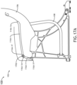
- FIGS. 17A-17B side views of an exemplary embodiment of the system 100 including the aircraft 102 including the aircraft seat 106 having compact aircraft seat base frame 108 and the seat pan assembly in a stowed state (as shown in FIG. 17A ) and a deployed state (as shown in FIG. 17B ) are depicted according to the inventive concepts.
- the seat pan assembly may include an aft driver link 114A-1 having an aft driver link fore end 114A-1F and an aft driver link aft end 114A-1A.
- the aft driver link aft end 114A-1A may be angled upward as compared to the rest of the aft driver link 114A-1.
- the seat pan assembly may include a fore driven link 116A-1 having a fore driven link fore end 116A-1F and a fore driven link aft end 116A-1A, and the fore driven link aft end 116A-1A may be pivotably coupled to the aft driver link fore end 114A-1F.
- the aft driver link aft end 114A-1A may be configured to rotate about the fore driven link aft end 116A-1A and cause the fore driven link fore end 116A-1F to rotate about the aft driver link fore end 114A-1F such that the fore driven link fore end 116A-1F is configured to move at least partially in an upward direction and forward direction, such as to a deployed seat pan state.
- the aft driver link aft end 114A-1A may be configured to rotate about the fore driven link aft end 116A-1A and cause the fore driven link fore end 116A-1F to rotate about the aft driver link fore end 114A-1F such that the fore driven link fore end 116A-1F is configured to move at least partially in a downward direction and aft direction, such as to a stowed state.
- the seat pan assembly may further comprise a gear 1702 having an outer gear component (e.g., which may be configured similarly to outer staggered gear component 140A or outer annular gear component 140A-1) and an inner gear component (e.g., which may be configured similarly to inner staggered gear component 140B or inner annular gear component 140B-1).
- the fore driven link aft end 116A-1A may have or be coupled to the inner gear component.
- the aft driver link fore end 114A-1F may have or be coupled to the outer gear component.
- the gear 1702 may be one of a staggered gear or an annular gear such that an initial amount of motion by the aft driver link produces no motion in the fore driven link.
- the seat pan assembly may further include a second aft driver link (e.g., which may be configured similarly to 114A-1) having a second aft driver link fore end and a second aft driver link aft end.
- the second aft driver link aft end may be angled upward as compared to the rest of the aft driver link.
- the seat pan assembly may include a fore driven link (e.g., which may be configured similarly to 116A-1) having a second fore driven link fore end and a second fore driven link aft end, and the second fore driven link aft end may be pivotably coupled to the second aft driver link fore end.
- the seat pan assembly may further include a second gear (e.g., which may be configured similarly to the gear 1702).
- the seat pan assembly may further include a fore seat pan section 128 connected between the second fore driven link and the fore driven link 116A-1.
- the seat pan assembly 110 may include an aft seat pan section 124 connected between the second aft driver link and the aft driver link 114A-1.
- each of the fore seat pan section 128 and the aft seat pan section 124 may be metal flex plan sections, which may provide sufficient support to a seated occupant and aid in the transfer of force needed to move seat pan assembly from a deployed state to a stowed state, or vice versa.
- each of the fore seat pan section 128and the aft seat pan section 124 may be riveted onto one of the links on each side so as to make the seat pan sections integral with each section of the seat pan assembly.
- embodiments of the inventive concepts disclosed herein may be directed to a system including a seat pan assembly.
- At least one means one or a plurality of; for example, “at least one” may comprise one, two, three, ..., one hundred, or more.
- one or more means one or a plurality of; for example, “one or more” may comprise one, two, three, ..., one hundred, or more.
- zero or more means zero, one, or a plurality of; for example, “zero or more” may comprise zero, one, two, three, ..., one hundred, or more.
- the methods, operations, and/or functionality disclosed may be implemented as sets of instructions or software readable by a device. Further, it is understood that the specific order or hierarchy of steps in the methods, operations, and/or functionality disclosed are examples of exemplary approaches. Based upon design preferences, it is understood that the specific order or hierarchy of steps in the methods, operations, and/or functionality can be rearranged while remaining within the scope of the inventive concepts disclosed herein.
- the accompanying claims may present elements of the various steps in a sample order, and are not necessarily meant to be limited to the specific order or hierarchy presented.
- embodiments of the methods according to the inventive concepts disclosed herein may include one or more of the steps described herein. Further, such steps may be carried out in any desired order and two or more of the steps may be carried out simultaneously with one another. Two or more of the steps disclosed herein may be combined in a single step, and in some embodiments, one or more of the steps may be carried out as two or more sub-steps. Further, other steps or sub-steps may be carried in addition to, or as substitutes to one or more of the steps disclosed herein.
Landscapes
- Engineering & Computer Science (AREA)
- Aviation & Aerospace Engineering (AREA)
- Transportation (AREA)
- Mechanical Engineering (AREA)
- Seats For Vehicles (AREA)
Abstract
Description
- The present application is related to and claims priority from:
Indian Application Serial Number 202211065766, titled SYSTEM INCLUDING SEAT PAN ASSEMBLY, filed November 16, 2022 US application 18/222,848 - Type III overwing exit egress requirements drive the spacing of seats in aircraft. The most constraining requirements surround the egress path toward the exit.
- In one aspect, there is provided a system. The system includes a seat pan assembly. The seat pan assembly may include a fixed link having a fore end and an aft end. The seat pan assembly may further include an aft driver link having an aft driver link fore end and an aft driver link aft end, wherein the aft driver link fore end is pivotably coupled to the aft end of the fixed link. The seat pan assembly may further include a fore driven link having a fore driven link fore end and a fore driven link aft end, wherein the fore driven link aft end is pivotably coupled to the fore end of the fixed link. When a downward component force acts upon the aft driver link, the aft driver link aft end is configured to rotate about the aft end of the fixed link and cause the fore driven link fore end to rotate about the fore end of the fixed link such that the fore driven link fore end is configured to move at least partially in an upward direction and forward direction.
- In a further aspect, a system includes a seat pan assembly. The seat pan assembly may include an aft driver link having an aft driver link fore end and an aft driver link aft end. The seat pan assembly may include a fore driven link having a fore driven link fore end and a fore driven link aft end, wherein the fore driven link aft end is pivotably coupled to the aft driver link fore end. When a downward component force acts upon the aft driver link, the aft driver link aft end is configured to rotate about the fore driven link aft end and cause the fore driven link fore end to rotate about the aft driver link fore end such that the fore driven link fore end is configured to move at least partially in an upward direction and forward direction.
- Implementations of the inventive concepts disclosed herein may be better understood when consideration is given to the following detailed description thereof. Such description makes reference to the included drawings, which are not necessarily to scale, and in which some features may be exaggerated and some features may be omitted or may be represented schematically in the interest of clarity. Like reference numerals in the drawings may represent and refer to the same or similar element, feature, or function. In the drawings:
-
FIG. 1 is a side view of a currently implemented system including an aircraft including an emergency egress path positioned between two rows of standard aircraft seats having standard aircraft seat base frames. -
FIG. 2 is a side view of an exemplary embodiment of the system including the aircraft including at least one emergency egress path positioned between two rows of aircraft seats (e.g., standard aircraft seats having standard aircraft seat base frames and aircraft seats having compact aircraft seat base frames and seat pan assemblies) according to the inventive concepts disclosed herein. -
FIG. 3 is a side view of an exemplary embodiment of the system ofFIG. 2 according to the inventive concepts disclosed herein. -
FIGS. 4A-4B are perspective views of an exemplary embodiment of the system including the aircraft including the aircraft seat having compact aircraft seat base frames and the seat pan assembly ofFIG. 2 in a stowed state (as shown inFIG. 4A ) and a deployed state (as shown inFIG. 4B ) according to the inventive concepts disclosed herein. - FIGS. 5A, 5B,
5C, and 5D are side views of an exemplary embodiment of the seat pan assembly ofFIGS. 4A-4B according to the inventive concepts disclosed herein. -
FIGS. 6A ,6B ,6C ,6D , and6E are perspective views of an exemplary embodiment of the seat pan assembly ofFIGS. 4A-4B according to the inventive concepts disclosed herein. -
FIGS. 7A ,7B , and7C are views of an exemplary embodiment of the seat pan assembly ofFIGS. 4A-4B according to the inventive concepts disclosed herein. -
FIGS. 8A ,8B ,8C , and8D are side views of an exemplary embodiment of the seat pan assembly ofFIGS. 4A-4B according to the inventive concepts disclosed herein. -
FIGS. 9A and9B are perspective views of an exemplary embodiment of the seat pan assembly ofFIGS. 4A-4B according to the inventive concepts disclosed herein. -
FIGS. 10A and10B are perspective views of an exemplary embodiment of a portion of the seat ofFIG. 2 including the seat pan assembly ofFIGS. 4A-4B according to the inventive concepts disclosed herein. -
FIG. 11 is a perspective view of an exemplary embodiment of the seat pan assembly ofFIGS. 4A-4B according to the inventive concepts disclosed herein. -
FIG. 12 is a side view of an exemplary embodiment of the seat pan assembly ofFIGS. 4A-4B according to the inventive concepts disclosed herein. -
FIG. 13 is a side view of an exemplary alternative embodiment of a portion of the seat ofFIG. 2 including a seat pan assembly according to the inventive concepts disclosed herein. -
FIG. 14 is a perspective side view of second exemplary alternative embodiment of a portion of the seat ofFIG. 2 including a seat pan assembly according to the inventive concepts disclosed herein. -
FIG. 15 is a side view of the exemplary alternative embodiment of the seat pan assembly ofFIG. 13 according to the inventive concepts disclosed herein. -
FIG. 16 is side view of an exemplary embodiment of a portion of the seat ofFIG. 2 including the seat pan assembly ofFIGS. 4A-4B according to the inventive concepts disclosed herein. -
FIGS. 17A-17B are side views of an exemplary embodiment of the seat pan assembly ofFIG. 2 according to the inventive concepts disclosed herein. - Before explaining at least one embodiment of the inventive concepts disclosed herein in detail, it is to be understood that the inventive concepts are not limited in their application to the details of construction and the arrangement of the components or steps or methodologies set forth in the following description or illustrated in the drawings. In the following detailed description of embodiments of the instant inventive concepts, numerous specific details are set forth in order to provide a more thorough understanding of the inventive concepts. However, it will be apparent to one of ordinary skill in the art having the benefit of the instant disclosure that the inventive concepts disclosed herein may be practiced without these specific details. In other instances, well-known features may not be described in detail to avoid unnecessarily complicating the instant disclosure. The inventive concepts disclosed herein are capable of other embodiments or of being practiced or carried out in various ways. Also, it is to be understood that the phraseology and terminology employed herein is for the purpose of description and should not be regarded as limiting.
- As used herein a letter following a reference numeral is intended to reference an embodiment of the feature or element that may be similar, but not necessarily identical, to a previously described element or feature bearing the same reference numeral (e.g., 1, 1a, 1b). Such shorthand notations are used for purposes of convenience only, and should not be construed to limit the inventive concepts disclosed herein in any way unless expressly stated to the contrary.
- Further, unless expressly stated to the contrary, "or" refers to an inclusive or and not to an exclusive or. For example, a condition A or B is satisfied by anyone of the following: A is true (or present) and B is false (or not present), A is false (or not present) and B is true (or present), and both A and B are true (or present).
- In addition, use of the "a" or "an" are employed to describe elements and components of embodiments of the instant inventive concepts. This is done merely for convenience and to give a general sense of the inventive concepts, and "a" and "an" are intended to include one or at least one and the singular also includes the plural unless it is obvious that it is meant otherwise.
- Finally, as used herein any reference to "one embodiment," or "some embodiments" means that a particular element, feature, structure, or characteristic described in connection with the embodiment is included in at least one embodiment of the inventive concepts disclosed herein. The appearances of the phrase "in some embodiments" in various places in the specification are not necessarily all referring to the same embodiment, and embodiments of the inventive concepts disclosed may include one or more of the features expressly described or inherently present herein, or any combination of sub-combination of two or more such features, along with any other features which may not necessarily be expressly described or inherently present in the instant disclosure.
- Broadly, embodiments of the inventive concepts disclosed herein are directed to a system including a seat pan assembly.
- Some embodiments offer a solution to maintain the overwing exit egress path when the aircraft seat is not occupied, such as during an emergency egress.
- In some embodiments, a seat pan assembly may move between an occupied state to a more compressed unoccupied state so as to open a greater emergency egress path during an evacuation. In some embodiments, the movement of the seat pan assembly may be damped and/or delayed to prevent movement of the seat pan assembly during a momentary seating position shift by a passenger.
- Some embodiments may provide an increased density (e.g., about 2-3" for a single overwing exit (OWE) and about 4-6" for dual OWE). The increased density may translate to increased profitability for the airline.
- Referring generally to
FIGS. 1-3 , side views of exemplary embodiments of asystem 100 including a vehicle (e.g.,aircraft 102, watercraft, automobile, train, etc.) including at least one emergency egress path 104 (e.g., at least one OWE emergency egress path) positioned between two rows of aircraft seats (e.g.,standard aircraft seats 106A having standard aircraft seat base frames 108A and/oraircraft seats 106 having compact aircraft seat base frames 108 andseat pan assemblies FIGS. 4A-16 )) depicted according to the inventive concepts. - Referring now to
FIG. 1 , a side view of a currently implementedsystem 100 including anaircraft 102 including anemergency egress path 104 positioned between two rows ofstandard aircraft seats 106A having standard aircraft seat base frames 108A is depicted.FIG. 1 depicts a typical situation on a Type III overwing aircraft.Standard aircraft seats 106A are installed at minimum distance for density but large enough to allow regulatoryminimum egress path 104 to the exit. A projected distance between the front most portion of theseat 106A at the exit and the aft most point of the seat forward of the exit must be maintained to ensure egress to the emergency exit. - Referring now to
FIGS. 2-3 , in some embodiments, it is desired to placeseats emergency egress path 104. Some embodiments may include an aircraft seat(s) 106 having a seat pan assembly 110 (such as shown inFIGS. 4A-16 )) and a compact aircraftseat base frame 108, which is desired to create a supported seat surface when an occupant sits on theseat 106 while presenting with a reduced surface when theseat 106 is not occupied. - Current regulations restrict any seat bottom portion from being above a bottom of an adjacent aircraft window. Additionally, current standard aircraft seat structures prevent downward motion of the standard aircraft seat cushion and support system.
- As shown in
FIG. 2 , a side view of an exemplary embodiment of asystem 100 including theaircraft 102 including at least one emergency egress path 104 (e.g., at least one OWE emergency egress path) positioned between two rows of aircraft seats (e.g.,standard aircraft seats 106A having standard aircraft seat base frames 108A andaircraft seats 106 having compact aircraft seat base frames 108 andseat pan assemblies FIGS. 4A-16 )) depicted according to the inventive concepts. - Some embodiments include a new compressed and/or
compact seat frame 108, which may be optimized for lower-weight, tight pitch seat assemblies which may be used for ultra high-density configurations suitable for use with some embodiments. In some embodiments, theaircraft seat 106 may have higher interface loads as a result of a lower leg-pitch (e.g., front stud to aft fitting pivot). In some embodiments, a reinforced floor structure in the overwing exit area may be used to allow for the higher loads in some applications. - As shown in
FIG. 3 , a side view of an exemplary embodiment of asystem 100 including theaircraft 102 including at least one emergency egress path 104 (e.g., at least one OWE emergency egress path) positioned between two rows of aircraft seats (e.g.,standard aircraft seats 106A having standard aircraft seat base frames 108A andaircraft seats 106 having compact aircraft seat base frames 108 andseat pan assemblies FIGS. 4A-16 )) depicted according to the inventive concepts. As shown inFIG. 3 , merely shortening the seat pan length, with no means to provide a standard seat length, would greatly reduce passenger comfort.FIG. 3 shows exemplary lengths of theaircraft seat 106's seat bottom (having theseat pan assembly 110A ofFIGS. 4A-16 ) in a deployedstate 110A and a stowedstate 110B. - As shown with respect to
FIGS. 2-17B , some embodiments may include a seat pan assembly that can extend for comfort when occupied but may be reduced in length when unoccupied, such as during an emergency evacuation. - Referring now to
FIGS. 4A-4B , perspective views of an exemplary embodiment of thesystem 100 including theaircraft 102 including theaircraft seat 106 having compact aircraft seat base frames 108 and theseat pan assembly 110 in a stowed state (as shown inFIG. 4A ) and a deployed state (as shown inFIG. 4B ) are depicted according to the inventive concepts. - The
seat pan assembly 110 may include a fixed link 112-1 having a fore end and an aft end. Theseat pan assembly 110 may include an aft driver link 114-1 having an aft driver link fore end and an aft driver link aft end, and the aft driver link fore end may be pivotably coupled to the aft end of the fixed link 112-1. In some embodiments, the aft driver link aft end may be angled upward as compared to the rest of the aft driver link 114-1. Theseat pan assembly 110 may include a fore driven link 116-1 having a fore driven link fore end and a fore driven link aft end, and the fore driven link aft end may be pivotably coupled to the fore end of the fixed link 112-1. - When a downward component force acts upon the aft driver link 114-1, the aft driver link aft end may be configured to rotate about the aft end of the fixed link 112-1 and cause the fore driven link fore end to rotate about the fore end of the fixed link 112-1 such that the fore driven link fore end is configured to move at least partially in an upward direction and forward direction, such as to a deployed seat pan state.
- When the downward component force ceases acting upon the aft driver link 114-1, the aft driver link aft end may be configured to rotate about the aft end of the fixed link 112-1 and cause the fore driven link fore end to rotate about the fore end of the fixed link 112-1 such that the fore driven link fore end is configured to move at least partially in a downward direction and aft direction, such as to a stowed state.
- The
seat pan assembly 110 may further include a second fixed link (such as shown better inFIG. 6A ) having a second fore end and a second aft end. Theseat pan assembly 110 may include a second aft driver link (such as shown better inFIG. 6A ) having a second aft driver link fore end and a second aft driver link aft end, and the second aft driver link fore end may be pivotably coupled to the second aft end of the second fixed link. Theseat pan assembly 110 may include a second fore driven link (such as shown better inFIG. 6A ) having a second fore driven link fore end and a second fore driven link aft end, and the second fore driven link aft end may be pivotably coupled to the second fore end of the second fixed link. Theseat pan assembly 110 may include anaft crossbar 120 connected between the second aft driver link aft end and the aft driver link aft end. Theseat pan assembly 110 may include afore crossbar 122 connected between the second fore driven link fore end and the fore driven link fore end. - When the downward component force acts upon the second aft driver link, the second aft driver link aft end may be configured to rotate about the second aft end of the second fixed link and cause the second fore driven link fore end to rotate about the second fore end of the second fixed link such that the second fore driven link fore end is configured to move at least partially in an upward direction and forward direction, such as to the deployed state.
- The
seat pan assembly 110 may further include a foreseat pan section 128 connected between the second fore driven link and the fore driven link 116-1. Theseat pan assembly 110 may include aseat pan section 126 connected between the second fixed link and the fixed link 112-1. Theseat pan assembly 110 may include an aftseat pan section 124 connected between the second aft driver link and the aft driver link 114-1. For example, each of the foreseat pan section 128, theseat pan section 126, and the aftseat pan section 124 may be metal flex plan sections, which may provide sufficient support to a seated occupant and aid in the transfer of force needed to moveseat pan assembly 110 from a deployed state to a stowed state, or vice versa. For example, each of the foreseat pan section 128, theseat pan section 126, and the aftseat pan section 124 may be riveted onto one of the links on each side so as to make the seat pan sections integral with each section of theseat pan assembly 110. - Referring now to FIGS. 5A
-5D , side views of an exemplary embodiment of theseat pan assembly 110 in a stowed state (as shown in FIGS. 5A and 5B) and a deployed state (as shown inFIGS. 5C and 5D ) depicted according to the inventive concepts. - As shown in FIGS. 5A
-5D , awire spring 130 may be coupled between the aft driver link 114-1 and the fixed link 112-1. For example, thewire spring 130 may be guided through holes in the aft driver link 114-1 and the fixed link 112-1 to provide a default stowed state to theseat pan assembly 110 when an occupant is not sitting on theseat 106. For example, through holes in the links 114-1, 112-1 may prevent thewire spring 130 from moving laterally. Thewire spring 130 may be deformable (e.g., deflectable) in response to an occupant sitting in theseat 106. Thewire spring 130 may provide the necessary force to position theseat pan assembly 110 in the stowed state when an occupant is not sitting in theseat 106. - Referring now to
FIGS. 6A-6E , various views of an exemplary embodiment of theseat pan assembly 110 are depicted according to the inventive concepts. - As shown in
FIG. 6A-6E , theseat pan assembly 110 may include a fixed link 112-1 having a fore end 112-1F and an aft end 112-1A. Theseat pan assembly 110 may include an aft driver link 114-1 having an aft driver link fore end 114-1F and an aft driver link aft end 114-1A, and the aft driver link fore end 114-1F may be pivotably coupled to the aft end 112-1A of the fixed link 112-1. In some embodiments, the aft driver link aft end 114-1A may be angled upward as compared to the rest of the aft driver link 114-1. Theseat pan assembly 110 may include a fore driven link 116-1 having a fore driven link fore end 116-1F and a fore driven link aft end 116-1A, and the fore driven link aft end 116-1A may be pivotably coupled to the fore end 112-1F of the fixed link 112-1. - The
seat pan assembly 110 may further include a second fixed link 112-2 having a second fore end 112-2F and a second aft end 112-2A. Theseat pan assembly 110 may include a second aft driver link 114-2 having a second aft driver link fore end 114-2F and a second aft driver link aft end 114-2A, and the second aft driver link fore end 114-2F may be pivotably coupled to the second aft end 112-2A of the second fixed link 112-2. Theseat pan assembly 110 may include a second fore driven link 116-2 having a second fore driven link fore end 116-2F and a second fore driven link aft end 116-2A, and the second fore driven link aft end 116-2A may be pivotably coupled to the second fore end 112-2F of the second fixed link 112-2. Theseat pan assembly 110 may include anaft crossbar 120 connected between the second aft driver link aft end 114-2A and the aft driver link aft end 114-1A. Theseat pan assembly 110 may include afore crossbar 122 connected between the second fore driven link fore end 116-2F and the fore driven link fore end 116-1F. - The
seat pan assembly 110 may further include adriver train 132 configured to transmit motion from the aft driver link 114-1 to the fore driven link 116-1. Thedriver train 132 may include a driver timing pulley 134 (as shown inFIGS. 6B and6C ), a driven pulley 140 (e.g., a driven timing pulley) (as shown inFIGS. 6D and6E ), and a timing belt 136 (as shown inFIGS. 6A-6E ) installed around thedriver timing pulley 134 and the drivenpulley 140. Thetiming belt 136 may be used to connect thepulleys timing belt 136 may ensure no transmission losses occur between thedriver timing pulley 134 and the drivenpulley 140. The motion amplification may be achieved because of the smaller angle of rotation by choosing a suitable pulley diameter ratio between thedriver timing pulley 134 and the drivenpulley 140. For example, thedriver timing pulley 134 may have a greater diameter than the drivenpulley 140. As shown in 6C, afirst fastener 138 may extend through thedriver timing pulley 134, the aft driver link fore end 114-1F, and the aft end 112-1A of the fixed link 112. As shown in 6E, asecond fastener 142 may extend through the drivenpulley 140, the fore driven link aft end 116-1A, and the fore end 112-1F of the fixed link 112. In some embodiments, the drivenpulley 140 may include multiple components (e.g., 140A, 140B). For example, the drivenpulley 140 may have a staggered gear including staggeredgear components pulley 140 may have an annular gear includingannular gear components 140A-1, 1408-1 (such as shown inFIG. 8D ) such that an initial amount (e.g., an initial 5-8 degrees) of motion by the aft driver link 114-1 produces no motion in the fore driven link 116-1. In some embodiments, thedriver train 132 further includes thewire spring 130 coupled between the aft driver link 114-1 and the fixed link 112. - In some embodiments, the
seat pan assembly 110 may further include a second driver train configured to transmit motion from the second aft driver link 114-2 to the fore driven link 116-2. The second driver train may function similarly to and have components similar to thedriver train 132. - Referring now to
FIGS. 7A-7C , various views of an exemplary embodiment ofdriver train 132 of theseat pan assembly 110 are depicted according to the inventive concepts. -
FIG. 7A shows theseat pan assembly 110 including thedriver train 132. -
FIG. 7B shows a cross-sectional view of a portion of thedriver train 132. For example, thefirst fastener 138 may extend through thedriver timing pulley 134, the aft driver link 114-1, the fixed link 112, afirst bearing 144, and anut 146. -
FIG. 7C shows a cross-sectional view of a portion of thedriver train 132. For example, thesecond fastener 142 may extend through the driven pulley 140 (e.g., 140A and 140B or 140A-1 and 140B-1), the fore driven link 116-1, the fixed link 112-1, asecond bearing 148, and asecond nut 150. - In some embodiments, the
driver train 132 and the fixed link 112-1 (as well as the second fixed link 112-2) may be replaced with an annular gear system (e.g., as shown inFIG. 8D ) such that an initial amount (e.g., an initial 5-8 degrees) of motion by the aft driver link 114-1 produces no motion in the fore driven link 116-1. - Referring now to
FIGS. 8A-8D , various views of an exemplary embodiment of thedriver train 132 of theseat pan assembly 110 are depicted according to the inventive concepts. -
FIG. 8A shows a perspective view of thedriver train 132 of theseat pan assembly 110. -
FIG. 8B shows a perspective view of the driven pulley 140 (e.g., 140A and 140B or 140A-1 and 140B-1) of thedriver train 132 of theseat pan assembly 110. -
FIG. 8C shows a cut-away view of the drivenpulley 140 comprised of the outerstaggered gear component 140A and the inner staggeredgear component 140B. For example, an initial x degrees (e.g., an initial 5-8 degrees) of motion by the aft driver link 114-1 produces no motion in the fore driven link 116-1 due to the outerstaggered gear component 140A moving unimpeded before driving teeth of the inner staggeredgear component 140B. -
FIG. 8D shows a cut-away view of the drivenpulley 140 comprised of an annular gear including an outerannular gear component 140A-1 and an innerannular gear component 140B-1. For example, an initial x degrees (e.g., an initial 5-8 degrees) of motion by the aft driver link 114-1 produces no motion in the fore driven link 116-1 due to the outerannular gear component 140A-1 having at least one more tooth than the the innerannular gear component 140B-1. - Referring now to
FIGS. 9A-9B , perspective views of an exemplary embodiment of thesystem 100 including theaircraft 102 including theaircraft seat 106 having compact aircraft seat base frames 108 and theseat pan assembly 110 in a deployed state depicted according to the inventive concepts. - The
seat pan assembly 110 may include a fixed link 112-1, an aft driver link 114-1, and a fore driven link 116-1. Theseat pan assembly 110 may further include a second fixed link 112-2, a second aft driver link 114-2 and a second fore driven link 116-2 (such as shown better inFIG. 6A ). Theseat pan assembly 110 may include anaft crossbar 120 connected between the second aft driver link aft end and the aft driver link aft end. Theseat pan assembly 110 may include afore crossbar 122 connected between the second fore driven link fore end and the fore driven link fore end. - The
seat pan assembly 110 may further include a foreseat pan section 128 connected between the second fore driven link 116-2 and the fore driven link 116-1. Theseat pan assembly 110 may include aseat pan section 126 connected between the second fixed link 112-2 and the fixed link 112-1. Theseat pan assembly 110 may include an aftseat pan section 124 connected between the second aft driver link 114-2 and the aft driver link 114-1. For example, each of the foreseat pan section 128, theseat pan section 126, and the aftseat pan section 124 may be metal flex plan sections, which may provide sufficient support to a seated occupant and aid in the transfer of force needed to moveseat pan assembly 110 from a deployed state to a stowed state, or vice versa. For example, each of the foreseat pan section 128, theseat pan section 126, and the aftseat pan section 124 may be riveted onto one of the links on each side so as to make the seat pan sections integral with each section of theseat pan assembly 110. - As shown in
FIG. 9B , theseat pan section 126 may have a slot (e.g., between agrommet 152 and the fixed link 112-1) to accommodate a portion of thetiming belt 136 passing from a top of thedriver timing pulley 134 to below theseat pan section 126 to the drivenpulley 140. The slot may have thegrommet 152 around edges of the slot to protect thetiming belt 136 from the edges of the slot. - As shown in
FIG. 9A , ashroud 118 may be attached to the fixed link 112-1 and may extend from the fixed link 112-1 to above thedriver timing pulley 134 and above thetiming belt 136. - Referring now to
FIGS. 10A-10B , perspective views of an exemplary embodiment of thesystem 100 including theaircraft 102 including theaircraft seat 106 having compact aircraft seat base frames 108 and theseat pan assembly 110 in a stowed state and a deployed state are depicted according to the inventive concepts. - As shown in
FIGS. 10A and10B , theaircraft seat 106 may include a forefoam seat section 158 installed above the foreseat pan section 128, afoam seat section 156 installed above theseat pan section 126, and an aftfoam seat section 154 installed above the aftseat pan section 124. The forefoam seat section 158, thefoam seat section 156, and the aftfoam seat section 154 may be shaped such that the forefoam seat section 158, thefoam seat section 156, and the aftfoam seat section 154 do not impede motion of the aft driver link 114-1 and the fore driven link 116-1. - Referring now to
FIG. 11 , a perspective views of an exemplary embodiment of theseat pan assembly 110 in a deployed state is depicted according to the inventive concepts. - Referring now to
FIG. 12 , a side view of an exemplary embodiment of theseat pan assembly 110 and thedriver train 132 in a stowed state is depicted according to the inventive concepts. - Referring now to
FIG. 13 , a side view of an exemplary embodiment of aseat pan assembly 110A and thedriver train 132 is depicted according to the inventive concepts. Theseat pan assembly 110A may function similarly to and have components similar to theseat pan assembly 110, except that theseat pan assembly 110A may have aspring 162 positioned under the aft driver link 114-1 and/or except that that theseat pan assembly 110A may have adamper 160. Thespring 162 may be configured to apply upward force on the aft driver link 114-1 such that a default position (when no passenger occupies the seat 106) is the stowed state. Thedamper 160 may be configured to prevent the fore driven link 116-1 from over-rotating past a desired amount of rotation when moving into the stowed position and/or when moving into the deployed state. - Referring now to
FIG. 14 , a perspective view of an exemplary embodiment of aseat 106 of aseat pan assembly 110 having a flex pan 164 (e.g., which may be composed of nylon) is depicted according to the inventive concepts. For example, theflex pan 164 may be composed of nylon fabric and intersecting nylon straps. - Referring now to
FIG. 15 , a side view of an exemplary embodiment of theseat pan assembly 110A and thedriver train 132 ofFIG. 13 is depicted according to the inventive concepts. In some embodiments, thedamper 160 may allow for a one-way damping motion such that when sitting, the fore driven link 116-1 is more quickly returned to its occupied position and deployed state. In some embodiments, the angle alpha may be approximately 1/2 of the angle beta; though any suitable ratios of angles may be used. - Referring now to
FIG. 16 , a side view of an exemplary embodiment of theaircraft seat 106 having the compact aircraftseat base frame 108 and theseat pan assembly 110 in a deployed state is depicted according to the inventive concepts. As shown, theaircraft seat 106 may include a forefoam seat section 158 installed above the foreseat pan section 128, afoam seat section 156 installed above theseat pan section 126, and an aftfoam seat section 154 installed above the aftseat pan section 124. Aseat cover 164 may cover the forefoam seat section 158, thefoam seat section 156, and the aftfoam seat section 154. - Referring now to
FIGS. 17A-17B , side views of an exemplary embodiment of thesystem 100 including theaircraft 102 including theaircraft seat 106 having compact aircraftseat base frame 108 and the seat pan assembly in a stowed state (as shown inFIG. 17A ) and a deployed state (as shown inFIG. 17B ) are depicted according to the inventive concepts. - The seat pan assembly may include an
aft driver link 114A-1 having an aft driver linkfore end 114A-1F and an aft driver link aftend 114A-1A. In some embodiments, the aft driver link aftend 114A-1A may be angled upward as compared to the rest of theaft driver link 114A-1. The seat pan assembly may include a fore drivenlink 116A-1 having a fore driven linkfore end 116A-1F and a fore driven linkaft end 116A-1A, and the fore driven linkaft end 116A-1A may be pivotably coupled to the aft driver linkfore end 114A-1F. - When a downward component force acts upon the
aft driver link 114A-1, the aft driver link aftend 114A-1A may be configured to rotate about the fore driven linkaft end 116A-1A and cause the fore driven linkfore end 116A-1F to rotate about the aft driver linkfore end 114A-1F such that the fore driven linkfore end 116A-1F is configured to move at least partially in an upward direction and forward direction, such as to a deployed seat pan state. - When the downward component force ceases acting upon the aft driver link 114-1, the aft driver link aft
end 114A-1A may be configured to rotate about the fore driven linkaft end 116A-1A and cause the fore driven linkfore end 116A-1F to rotate about the aft driver linkfore end 114A-1F such that the fore driven linkfore end 116A-1F is configured to move at least partially in a downward direction and aft direction, such as to a stowed state. - In some embodiments, the seat pan assembly may further comprise a
gear 1702 having an outer gear component (e.g., which may be configured similarly to outerstaggered gear component 140A or outerannular gear component 140A-1) and an inner gear component (e.g., which may be configured similarly to inner staggeredgear component 140B or innerannular gear component 140B-1). The fore driven linkaft end 116A-1A may have or be coupled to the inner gear component. The aft driver linkfore end 114A-1F may have or be coupled to the outer gear component. For example, thegear 1702 may be one of a staggered gear or an annular gear such that an initial amount of motion by the aft driver link produces no motion in the fore driven link. - The seat pan assembly may further include a second aft driver link (e.g., which may be configured similarly to 114A-1) having a second aft driver link fore end and a second aft driver link aft end. In some embodiments, the second aft driver link aft end may be angled upward as compared to the rest of the aft driver link. The seat pan assembly may include a fore driven link (e.g., which may be configured similarly to 116A-1) having a second fore driven link fore end and a second fore driven link aft end, and the second fore driven link aft end may be pivotably coupled to the second aft driver link fore end. The seat pan assembly may further include a second gear (e.g., which may be configured similarly to the gear 1702).
- The seat pan assembly may further include a fore
seat pan section 128 connected between the second fore driven link and the fore drivenlink 116A-1. Theseat pan assembly 110 may include an aftseat pan section 124 connected between the second aft driver link and theaft driver link 114A-1. For example, each of the foreseat pan section 128 and the aftseat pan section 124 may be metal flex plan sections, which may provide sufficient support to a seated occupant and aid in the transfer of force needed to move seat pan assembly from a deployed state to a stowed state, or vice versa. For example, each of the fore seat pan section 128and the aftseat pan section 124 may be riveted onto one of the links on each side so as to make the seat pan sections integral with each section of the seat pan assembly. - As will be appreciated from the above, embodiments of the inventive concepts disclosed herein may be directed to a system including a seat pan assembly.
- As used throughout, "at least one" means one or a plurality of; for example, "at least one" may comprise one, two, three, ..., one hundred, or more. Similarly, as used throughout, "one or more" means one or a plurality of; for example, "one or more" may comprise one, two, three, ..., one hundred, or more. Further, as used throughout, "zero or more" means zero, one, or a plurality of; for example, "zero or more" may comprise zero, one, two, three, ..., one hundred, or more.
- In the present disclosure, the methods, operations, and/or functionality disclosed may be implemented as sets of instructions or software readable by a device. Further, it is understood that the specific order or hierarchy of steps in the methods, operations, and/or functionality disclosed are examples of exemplary approaches. Based upon design preferences, it is understood that the specific order or hierarchy of steps in the methods, operations, and/or functionality can be rearranged while remaining within the scope of the inventive concepts disclosed herein. The accompanying claims may present elements of the various steps in a sample order, and are not necessarily meant to be limited to the specific order or hierarchy presented.
- It is to be understood that embodiments of the methods according to the inventive concepts disclosed herein may include one or more of the steps described herein. Further, such steps may be carried out in any desired order and two or more of the steps may be carried out simultaneously with one another. Two or more of the steps disclosed herein may be combined in a single step, and in some embodiments, one or more of the steps may be carried out as two or more sub-steps. Further, other steps or sub-steps may be carried in addition to, or as substitutes to one or more of the steps disclosed herein.
- From the above description, it is clear that the inventive concepts disclosed herein are well adapted to carry out the objects and to attain the advantages mentioned herein as well as those inherent in the inventive concepts disclosed herein. While presently preferred embodiments of the inventive concepts disclosed herein have been described for purposes of this disclosure, it will be understood that changes may be made which fall within the scope of the invention as defined by the claims.
Claims (15)
- A system, comprising: a seat pan assembly (110), comprising:a fixed link (112-1) having a fore end and an aft end;an aft driver link (114-1) having an aft driver link fore end and an aft driver link aft end, wherein the aft driver link fore end is pivotably coupled to the aft end of the fixed link; anda fore driven link (116-1) having a fore driven link fore end and a fore driven link aft end, wherein the fore driven link aft end is pivotably coupled to the fore end of the fixed link;wherein, when a downward component force acts upon the aft driver link, the aft driver link aft end is configured to rotate about the aft end of the fixed link and cause the fore driven link fore end to rotate about the fore end of the fixed link such that the fore driven link fore end is configured to move at least partially in an upward direction and forward direction.
- The system of claim 1, further comprising an aircraft seat (106A) comprising the seat pan assembly.
- The system of claim 2, wherein, when the downward component force ceases acting upon the aft driver link, the aft driver link aft end is configured to rotate about the aft end of the fixed link and cause the fore driven link fore end to rotate about the fore end of the fixed link such that the fore driven link fore end is configured to move at least partially in a downward direction and aft direction.
- The system of any preceding claim, wherein the seat pan assembly further comprises:a second fixed link (112-2) having a second fore end and a second aft end;a second aft driver link (114-2) having a second aft driver link fore end and a second aft driver link aft end, wherein the second aft driver link fore end is pivotably coupled to the second aft end of the second fixed link;a second fore driven link (116-2) having a second fore driven link fore end and a second fore driven link aft end, wherein the second fore driven link aft end is pivotably coupled to the second fore end of the second fixed link;an aft crossbar (120) connected between the second aft driver link aft end and the aft driver link aft end; anda fore crossbar (122) connected between the second fore driven link fore end and the fore driven link fore end;wherein, when the downward component force acts upon the second aft driver link, the second aft driver link aft end is configured to rotate about the second aft end of the second fixed link and cause the second fore driven link fore end to rotate about the second fore end of the second fixed link such that the second fore driven link fore end is configured to move at least partially in an upward direction and forward direction.
- The system of any preceding claim, wherein the seat pan assembly further comprises:a driver train (132) configured to transmit motion from the aft driver link to the fore driven link, and optionally wherein the driver train comprises:a driver timing pulley (134);a driven pulley (140); anda timing belt (136) installed around the driver timing pulley and the driven pulley.
- The system of claim 5, wherein the driver train further comprises:a first fastener (138) extending through the driver timing pulley, the aft driver link fore end, and the aft end of the fixed link; anda second fastener (142) extending through the driven pulley, the fore driven link aft end, and the fore end of the fixed link, and optionally wherein the driver timing pulley has a greater diameter than the driven pulley.
- The system of claim 6, wherein the driven pulley has one of a staggered gear (140A, 140B) or an annular gear (140A-1, 140B-1) such that an initial amount of motion by the aft driver link produces no motion in the fore driven link, and optionally wherein the driven pulley has the staggered gear such that an initial amount of motion by the aft driver link produces no motion in the fore driven link.
- The system of any preceding claim, wherein the seat pan assembly further comprises a wire spring (130) coupled between the aft driver link and the fixed link.
- The system of claim 4 or any claim dependent thereon, wherein the seat pan assembly further comprises:a fore seat pan section (128) connected between the second fore driven link and the fore driven link;a seat pan section (126) connected between the second fixed link and the fixed link; andan aft seat pan section (124) connected between the second aft driver link and the aft driver link.
- The system of claim 9, wherein the seat pan section has a slot to accommodate a portion of the timing belt passing from a top of the driver timing pulley to below the seat pan section to the driven pulley, and optionally wherein the slot has a grommet (152) around edges of the slot to protect the timing belt from the edges of the slot.
- The system of claim 5 or any claim dependent thereon, further comprising a shroud (118) attached to the fixed link and extending from the fixed link to above the driver timing pulley and above the timing belt.
- The system of claim 11, further comprising:a fore foam seat section (158) installed above the fore seat pan section;a foam seat section (156) installed above the seat pan section; andan aft foam seat section (154) installed above the aft seat pan section;wherein the fore foam seat section, the foam seat section, and the aft foam seat section are shaped such that the fore foam seat section, the foam seat section, and the aft foam seat section do not impede motion of the aft driver link and the fore driven link.
- A system, comprising:
a seat pan assembly, comprising:an aft driver link (114-1) having an aft driver link fore end and an aft driver link aft end; anda fore driven link (116-1) having a fore driven link fore end and a fore driven link aft end, wherein the fore driven link aft end is pivotably coupled to the aft driver link fore end;wherein, when a downward component force acts upon the aft driver link, the aft driver link aft end is configured to rotate about the fore driven link aft end and cause the fore driven link fore end to rotate about the aft driver link fore end such that the fore driven link fore end is configured to move at least partially in an upward direction and forward direction. - The system of claim 13, further comprising an aircraft seat comprising the seat pan assembly, wherein the seat pan assembly further comprises a gear (140A, 140B) having an outer gear component and an inner gear component, wherein the fore driven link aft end has or is coupled to the inner gear component, wherein the aft driver link fore end has or is coupled to the outer gear component.
- The system of claim 14, wherein the gear is one of a staggered gear or an annular gear such that an initial amount of motion by the aft driver link produces no motion in the fore driven link.
Applications Claiming Priority (2)
| Application Number | Priority Date | Filing Date | Title |
|---|---|---|---|
| IN202211065766 | 2022-11-16 | ||
| US18/222,848 US20240158086A1 (en) | 2022-11-16 | 2023-07-17 | System including seat pan assembly |
Publications (1)
| Publication Number | Publication Date |
|---|---|
| EP4371816A1 true EP4371816A1 (en) | 2024-05-22 |
Family
ID=88837527
Family Applications (1)
| Application Number | Title | Priority Date | Filing Date |
|---|---|---|---|
| EP23210030.5A Pending EP4371816A1 (en) | 2022-11-16 | 2023-11-15 | System including seat pan assembly |
Country Status (1)
| Country | Link |
|---|---|
| EP (1) | EP4371816A1 (en) |
Citations (3)
| Publication number | Priority date | Publication date | Assignee | Title |
|---|---|---|---|---|
| JP2002119347A (en) * | 2000-10-16 | 2002-04-23 | Takano Co Ltd | Chair |
| WO2012011452A1 (en) * | 2010-07-18 | 2012-01-26 | 株式会社デルタツーリング | Cushion-material support mechanism and seat |
| CN110494324A (en) * | 2017-03-23 | 2019-11-22 | 空中客车德国运营有限责任公司 | Passenger Seat and Cabin Area with Expandable Seat Elements |
-
2023
- 2023-11-15 EP EP23210030.5A patent/EP4371816A1/en active Pending
Patent Citations (3)
| Publication number | Priority date | Publication date | Assignee | Title |
|---|---|---|---|---|
| JP2002119347A (en) * | 2000-10-16 | 2002-04-23 | Takano Co Ltd | Chair |
| WO2012011452A1 (en) * | 2010-07-18 | 2012-01-26 | 株式会社デルタツーリング | Cushion-material support mechanism and seat |
| CN110494324A (en) * | 2017-03-23 | 2019-11-22 | 空中客车德国运营有限责任公司 | Passenger Seat and Cabin Area with Expandable Seat Elements |
Similar Documents
| Publication | Publication Date | Title |
|---|---|---|
| US10953780B2 (en) | Deployable infill assembly and passenger seat construction | |
| EP0256749B1 (en) | Energy absorbing aircraft seat frame structure | |
| US9452838B2 (en) | Independently articulating seat pan for aircraft seat | |
| EP3868665B1 (en) | Seat assembly with sacrificial backrest breakover feature | |
| EP3393906B1 (en) | Passenger seat having a displaceable seat element | |
| US4832409A (en) | Restraint belt load capacity fore and aft power seat adjuster apparatus | |
| US20150307194A1 (en) | Aircraft seat with occupant weight sensing mechanism to adjust tilt-recline force | |
| US20240158086A1 (en) | System including seat pan assembly | |
| EP4335745B1 (en) | Aircraft seat with energy attenuating metering plate | |
| EP4592183A1 (en) | Multi-angle and translational seat pan bearing mechanism | |
| EP3670344B1 (en) | Extendable split headrest | |
| EP3490838B1 (en) | A seat system | |
| EP4353589A1 (en) | Offset helicopter pilot seat with centered vertical motion system | |
| US5499788A (en) | Manual seat adjuster | |
| US12049320B2 (en) | Passenger seating assembly with swinging seatpan for increased passenger egress space | |
| EP4592179A1 (en) | Passenger seat with coupled linkage and cradled recline motion | |
| EP4592182A1 (en) | Aircraft passenger seat assembly with over center breakover link | |
| EP4223640B1 (en) | Armrest assembly with hidden pivot shaft and discreet retention | |
| EP4144646B1 (en) | Spreader with open slot for passenger seat | |
| EP4353593B1 (en) | Aircraft seat with nested energy attenuation guide system | |
| EP4015385B1 (en) | Aircraft passenger seat row with cabin attendant seat | |
| EP4506252A1 (en) | Row of passenger seats convertible to a bed | |
| EP3774540B1 (en) | Movable ottoman for an aircraft seat | |
| EP4223642A1 (en) | Passenger seating assembly with swinging seatpan for increased passenger egress space | |
| US12195187B2 (en) | Offset helicopter pilot seat with singular energy absorber |
Legal Events
| Date | Code | Title | Description |
|---|---|---|---|
| PUAI | Public reference made under article 153(3) epc to a published international application that has entered the european phase |
Free format text: ORIGINAL CODE: 0009012 |
|
| STAA | Information on the status of an ep patent application or granted ep patent |
Free format text: STATUS: THE APPLICATION HAS BEEN PUBLISHED |
|
| AK | Designated contracting states |
Kind code of ref document: A1 Designated state(s): AL AT BE BG CH CY CZ DE DK EE ES FI FR GB GR HR HU IE IS IT LI LT LU LV MC ME MK MT NL NO PL PT RO RS SE SI SK SM TR |
|
| STAA | Information on the status of an ep patent application or granted ep patent |
Free format text: STATUS: REQUEST FOR EXAMINATION WAS MADE |
|
| 17P | Request for examination filed |
Effective date: 20241121 |
|
| RBV | Designated contracting states (corrected) |
Designated state(s): AL AT BE BG CH CY CZ DE DK EE ES FI FR GB GR HR HU IE IS IT LI LT LU LV MC ME MK MT NL NO PL PT RO RS SE SI SK SM TR |