EP4371788A1 - Tire stud with anchoring elements - Google Patents
Tire stud with anchoring elements Download PDFInfo
- Publication number
- EP4371788A1 EP4371788A1 EP23210506.4A EP23210506A EP4371788A1 EP 4371788 A1 EP4371788 A1 EP 4371788A1 EP 23210506 A EP23210506 A EP 23210506A EP 4371788 A1 EP4371788 A1 EP 4371788A1
- Authority
- EP
- European Patent Office
- Prior art keywords
- stud
- tire
- stud body
- anchoring elements
- anchoring
- Prior art date
- Legal status (The legal status is an assumption and is not a legal conclusion. Google has not performed a legal analysis and makes no representation as to the accuracy of the status listed.)
- Granted
Links
Images


Classifications
-
- B—PERFORMING OPERATIONS; TRANSPORTING
- B60—VEHICLES IN GENERAL
- B60C—VEHICLE TYRES; TYRE INFLATION; TYRE CHANGING; CONNECTING VALVES TO INFLATABLE ELASTIC BODIES IN GENERAL; DEVICES OR ARRANGEMENTS RELATED TO TYRES
- B60C11/00—Tyre tread bands; Tread patterns; Anti-skid inserts
- B60C11/14—Anti-skid inserts, e.g. vulcanised into the tread band
- B60C11/16—Anti-skid inserts, e.g. vulcanised into the tread band of plug form, e.g. made from metal, textile
- B60C11/1637—Attachment of the plugs into the tread, e.g. screwed
-
- B—PERFORMING OPERATIONS; TRANSPORTING
- B60—VEHICLES IN GENERAL
- B60C—VEHICLE TYRES; TYRE INFLATION; TYRE CHANGING; CONNECTING VALVES TO INFLATABLE ELASTIC BODIES IN GENERAL; DEVICES OR ARRANGEMENTS RELATED TO TYRES
- B60C11/00—Tyre tread bands; Tread patterns; Anti-skid inserts
- B60C11/14—Anti-skid inserts, e.g. vulcanised into the tread band
- B60C11/16—Anti-skid inserts, e.g. vulcanised into the tread band of plug form, e.g. made from metal, textile
- B60C11/1643—Anti-skid inserts, e.g. vulcanised into the tread band of plug form, e.g. made from metal, textile with special shape of the plug-body portion, i.e. not cylindrical
- B60C11/1668—Anti-skid inserts, e.g. vulcanised into the tread band of plug form, e.g. made from metal, textile with special shape of the plug-body portion, i.e. not cylindrical with an additional collar
Definitions
- the present invention relates to a tire stud comprising a stud body and one or more foldable anchoring elements attached to the stud body.
- the present invention further relates to a tire, preferably a pneumatic tire, comprising said tire stud and to a method of inserting said tire stud into a tire tread.
- Such tire stud is of particular value for use on winter, snow and/or ice tires.
- the invention relates to a tire stud in accordance with claim 1, to a tire in accordance with claim 14 and to a method in accordance with claim 15.
- the tire studs according to the present invention are better retained in the borehole of the tread of the pneumatic tire increasing greatly the durability of the tire stud and their efficacy for winter, snow and/or ice pneumatic tires.
- the term “radial” or “radial direction” refers to a length or distance that is parallel to the axis from the top of the pin of the tire stud to the bottom of the stud body. Hence, the radial direction is parallel to the axis of rotation or to the symmetry axis of the tire stud, if any.
- “Radial” also refers to the direction when the tire stud is inserted into the tread of a tire, i.e., in accordance with its intended use. Hence, a "radial" direction of the tire stud is also a radial direction of the tire.
- axial refers to a length or distance that is perpendicular to the radial direction.
- Axial also refers to the direction when the tire stud is inserted into the tread of a tire, i.e., in accordance with its intended use.
- an "axial" direction of the tire stud is also an axial direction of the tire, i.e., parallel to the axis of rotation of the tire.
- each anchoring element is foldable at the junction between said anchoring element and the stud body.
- n 2 or more, such that the tire stud comprises two or more foldable anchoring elements E B (n).
- the junction between the anchoring elements and the stud body is located in the upper part of the bottom portion P B of the stud body.
- the foldable anchoring elements are positioned in the same horizontal plan.
- n is in the range of from 2 to 10, more preferably in the range of from 2 to 8, more preferably in the range of from 3 to 6.
- the tire stud comprises three foldable anchoring elements E B (1), E B (2) and E B (3) or four foldable anchoring elements E B (1), E B (2), E B (3) and E B (4), which are spaced from one another, more preferably equally spaced from one another.
- At least one anchoring element E B (1) of the n foldable anchoring elements E B (n), more preferably each element E B (n), has a length L EB in the range of from 0.25 to 6 mm, more preferably in the range of from 0.5 to 5 mm, more preferably in the range of from 1 to 4 mm, the length L EB being the axial distance between the most outward end point of the element and the end point of the element in contact with the stud body.
- each of the n foldable anchoring elements E B (n) has a maximal width W EB in the range of from 0.25 to 7 mm, more preferably in the range of from 0.5 to 6 mm, more preferably in the range of from 1 to 4 mm.
- the foldable anchoring elements E B (n) have a substantially rectangular shape, substantially triangular shape, half-moon shape or trapezoidal shape, more preferably a substantially rectangular shape.
- the n foldable anchoring elements are foldable anchoring wings.
- m is in the range of from 2 to 10, more preferably in the range of from 2 to 8, more preferably in the range of from 3 to 6.
- the tire stud comprises three foldable anchoring elements E I (1), E I (2) and E I (3) or four foldable anchoring elements E I (1), E I (2), E I (3) and E I (4) which are spaced from one another, more preferably equally spaced from one another.
- the foldable anchoring elements E I (m) are positioned in the same horizontal plan.
- At least one anchoring element, more preferably each element, of the m foldable anchoring elements E I (m) has a length L EI in the range of from 0.25 to 6 mm, more preferably in the range of from 0.5 to 5 mm, more preferably in the range of from 1 to 4 mm, the length L EI being the axial distance between the most outward end point of the element and the end point of the element in contact with the stud body.
- L EI L EB .
- one foldable anchoring element, more preferably each element, of the m foldable anchoring elements E I (m) has a maximal width W EI in the range of from 0.25 to 7 mm, more preferably in the range of from 0.5 to 6 mm, more preferably in the range of from 1 to 4 mm.
- W EI W EB .
- the foldable anchoring elements E I (m) have a substantially rectangular shape, substantially triangular shape, half-moon shape or trapezoidal shape, more preferably a substantially rectangular shape. More preferably, the foldable anchoring elements E I (m) have the same shape as the foldable anchoring elements E B (n).
- n m.
- the m foldable anchoring elements E I (m) are foldable anchoring wings.
- the foldable anchoring elements E B (n) comprise at least one polymer, more preferably the anchoring elements are made of the same at least one polymer of the stud body.
- the foldable anchoring elements E B (n) are at least partially flexible.
- the foldable anchoring elements E I (m) are at least partially flexible.
- the foldable anchoring elements E I (m) comprise at least one polymer, more preferably the anchoring elements are made of the same at least one polymer of the stud body.
- all foldable anchoring elements of the tire stud are made of the same material as the material used for the stud body.
- n 1 such that the tire stud comprises one foldable anchoring element E B (1).
- the foldable anchoring element is a foldable anchoring collar.
- the junction between the anchoring element and the stud body is located in the lower part of the bottom portion P B of the stud body.
- the foldable anchoring collar has a maximal width is in the range of from 0.25 to 7 mm, more preferably in the range of from 0.5 to 6 mm, more preferably in the range of from 1 to 4 mm.
- the foldable anchoring collar has a regular circular shape or an irregular circular shape.
- the collar has an irregular circular shape, it means that it can comprise one or more protrusions.
- the foldable anchoring collar is attached all around the stud body and is foldable at the junction of the stud body and the collar.
- the foldable anchoring collar comprises at least one polymer, more preferably the foldable anchoring collar is made of the same at least one polymer of the stud body.
- the foldable anchoring collar is at least partially flexible.
- the foldable anchoring collar is made of the same material as the material used for the stud body.
- the stud body may have any shapes. Examples of shapes are illustrated in the figures of the present invention.
- the at least one polymer comprised in the stud body is selected from the group consisting of polyetheretherketone (PEEK), polyphenylene sulfide (PPS), polyphenyl ether (PPE), polypropylene (PP), polyethylene (PE), polycarbonate (PC), polysulfone (PSU), polyetherimide (PEI), polyphenylene sulfone (PPSU), polyarylamide (PARA), polyamine (PA), syndiotactic 1,2-polybutadiene (SPBD), phenolic resin, melamine resin, epoxy resin, benzoxazine-based polymer, cyanate ester resin, polyurethane (PU), polyacrylic ester, a polyimide and a mixture of two or more thereof.
- PEEK polyetheretherketone
- PPS polyphenylene sulfide
- PPE polyphenyl ether
- PP polypropylene
- PE polyethylene
- PC polycarbonate
- PSU polysulfone
- SPBD offers the advantage of becoming securely bound to the rubber of the tire tread. It is believed that the syndiotactic 1,2-polybutadiene (SPBD) co-cures with the rubber of the tire tread during the curing of the tire, resulting in a strong adhesion between the SPBD and the tire tread.
- SPBD can be prepared in an inert organic solvent utilizing the technique described in U.S. Patent No. 3,901,868 or in an aqueous medium utilizing the process described in U.S. Patent No. 4,506,031 . The latter more specifically reveals a process for producing polybutadiene composed essentially of SPBD comprising the steps of:
- the SPBD utilized for preparing the stud body comprised in the tire stud of the present invention has a melting point of 160°C or less, more preferably in the range of from 70°C to 160°C, more preferably in the range of from 80°C to 150°C, more preferably in the range of from 90°C to 125°C.
- the melting points referred to herein are the minimum endotherm values determined from DSC ( differential scanning calorimetry) curves.
- the stud body comprises a blend of polymers, including SPDB (from 25 to 75 weight - percent based on the weight of the blend) and at least one rubber (from 75 to 25 weight - percent based on the weight of the blend) which is curable with the SPBD.
- the rubber component used in such blends can be virtually any type of elastomer which contains unsaturation that allows for sulfur curing.
- the elastomer will be one or more polydiene rubbers.
- suitable polydiene rubbers include cis-1,4-polybutadiene, natural rubber, synthetic polyisoprene, styrene butadiene rubber, EPDM (ethylenepropylene- diene monomer) rubbers, isoprene-butadiene rubbers, and styreneisoprene-butadiene rubbers.
- EPDM ethylenepropylene- diene monomer
- the rubber portion of the blend can be a combination of chlorobutyl rubber, natural rubber, and EPDM rubber.
- a the rubber component comprises from 30 to 80 weight - percent, more preferably from 55 to 65 weight - percent, chlorobutyl rubber, from 15 to 55 weight - percent, more preferably from 25 to 45 weight - percent, natural rubber, and from 2 to 10 weight - percent, more preferably from 3 to 7 weight - percent, EPDM, the weight percent being based on the weight of the rubber component.
- the inclusion of high content of SPBD in the stud body results in better adhesion, abrasion, and tear resistance for the cured material.
- High contents of SPBD also result in increased green strength and stiffness.
- the use of high levels of SPBD reduces green tack which makes handling.
- the incorporation of large amounts of SPBD into the blend also results in reduced flexibility and modulus.
- the blend utilized preferably contains from 33 to 67 weight - percent SPBD and from 67 to 33 weight - percent co-curable rubbers. More preferably, the blend in the stud body contains from 45 to 55 weight - percent SPBD and from 55 to 45 weight - percent of the elastomeric component.
- the SPBD used for preparing the blend can be in powder or pellet form.
- the SPBD powder or pellets can be mixed into the rubber component utilizing standard mixing techniques. However, the mixing is normally carried out at a temperature which is at least as high as the melting point of the SPBD being utilized. During the mixing procedure, the SPBD powder pellets are fluxed into the rubber with additional desired compounding ingredients. Such mixing is typically carried out in a Banbury mixer, a mill mixer or in some other suitable type of mixing device.
- Such blends of SPBD and rubber component may further contain other standard rubber chemicals.
- such blends may contain sulfur and at least one desired colorant or pigment, e.g. titanium dioxide can be of interest as it can be used as pigment and filler. They will also typically contain other rubber chemicals, such as antioxidants, accelerators, oils, and waxes in conventional amounts.
- desired colorant or pigment e.g. titanium dioxide
- antioxidants, accelerators, oils, and waxes e.g.
- the typical content of sulfur and first and secondary accelerators are disclosed in U.S. Patent Publication No. 2021/0008930 which is incorporated herein.
- the stud body is reinforced with one or more fibers.
- the one or more fibers are glass fibers, woven fibers or staple fibers.
- the stud body may further comprise one or more of a pigment and a dye.
- the at least one polymer comprised in the n foldable anchoring elements E B (n) of the tire stud is selected from the group consisting of polyetheretherketone (PEEK), polyphenylene sulfide (PPS), polyphenyl ether (PPE), polypropylene (PP), polyethylene (PE), polycarbonate (PC), polysulfone (PSU), polyetherimide (PEI), polyphenylene sulfone (PPSU), polyarylamide (PARA), polyamine (PA), syndiotactic 1,2-polybutadiene (SPBD), phenolic resin, melamine resin, epoxy resin, benzoxazine-based polymer, cyanate ester resin, polyurethane (PU), polyacrylic ester, a polyimide and a mixture of two or more thereof.
- PEEK polyetheretherketone
- PPS polyphenylene sulfide
- PPE polyphenyl ether
- PP polypropylene
- PE polyethylene
- the at least one polymer comprised in the m foldable anchoring elements E I (n) of the tire stud is selected from the group consisting of polyetheretherketone (PEEK), polyphenylene sulfide (PPS), polyphenyl ether (PPE), polypropylene (PP), polyethylene (PE), polycarbonate (PC), polysulfone (PSU), polyetherimide (PEI), polyphenylene sulfone (PPSU), polyarylamide (PARA), polyamine (PA), syndiotactic 1,2-polybutadiene (SPBD), phenolic resin, melamine resin, epoxy resin, benzoxazine-based polymer, cyanate ester resin, polyurethane (PU), polyacrylic ester, a polyimide and a mixture of two or more thereof.
- PEEK polyetheretherketone
- PPS polyphenylene sulfide
- PPE polyphenyl ether
- PP polypropylene
- PE polyethylene
- the foldable anchoring element(s) of the tire stud is(are) reinforced with one or more fibers.
- the one or more fibers are glass fibers, woven fibers or staple fibers.
- the foldable anchoring element(s) of the tire stud may further comprise one or more of a pigment and a dye.
- the stud body and the n foldable anchoring elements E B (n) of the tire stud are made of the same material.
- the stud body and the m foldable anchoring elements E I (m) of the tire stud are made of the same material.
- the stud body and the n foldable anchoring elements are produced in one piece.
- the stud body and the n foldable anchoring elements are formed/produced by injection molding or the like. Indeed, thanks to the stiffness and elasticity of the used polymer, the element(s) can be folded and unfolded at the junction stud body/element.
- the stud body and any foldable anchoring elements of the tire stud are produced in one piece.
- the stud body and any foldable anchoring elements of the tire stud are formed/produced by injection molding or the like.
- the stud body presents one or more constrictions, wherein the width of the stud body in the one or more constriction areas is lower than the width of the stud body in the non-constriction areas.
- the stud body presents one or more constrictions, wherein the width of the stud body in the one or more constriction areas is lower than the width of the stud body in the non-constriction areas.
- the stud body presents one constriction.
- the stud body presents a constriction at the upper part of P I and a constriction at the lower part of P I with a bead between said constrictions. This is in particular illustrated in FIG. 3 .
- the width of the bead is equal to from 95 to 105 percent, more preferably from 98 to 102 percent, more preferably from 99 to 101 percent, of the maximal width of the stud body in the top portion.
- the width of the bead is equal to from 95 to 105 percent, more preferably from 98 to 102 percent, more preferably from 99 to 101 percent, of the maximal width of the stud body in the bottom portion.
- the foldable anchoring elements E I (m) are attached to the bead of the stud body.
- the foldable anchoring elements E I (m) in P I are as defined in the foregoing.
- the stud body presents no constriction. This is in particular illustrated in FIG. 1 , 5 and 6 , wherein there is also no anchoring elements in P I and P T .
- top portion P T , the intermediate portion P I and the bottom portion P B of the stud body have the same or different shapes.
- the present invention further relates to a pneumatic tire comprising at least one tire stud according to the present invention.
- the pneumatic tire further comprises a tread, wherein the tread comprises the at least one tire stud, more preferably a plurality of tire studs according to the present invention, embedded therein.
- the pin comprised in the at least one stud extends out of the tread.
- the pneumatic tire is a winter, snow and/or ice pneumatic tire.
- the present invention is further illustrated by the following set of embodiments and combinations of embodiments resulting from the dependencies and back-references as indicated.
- every embodiment in this range is meant to be explicitly disclosed for the skilled person, i.e. the wording of this term is to be understood by the skilled person as being synonymous to "The tire stud of any one of embodiments 1, 2 and 3".
- the following set of embodiments represents a suitably structured part of the general description directed to preferred aspects of the present invention, and, thus, suitably supports, but does not represent the claims of the present invention.
- the tire stud comprises
- each anchoring element is foldable at the junction between said anchoring element and the stud body.
- the tire stud of embodiment 1 or 2 wherein, in P B , the tire stud comprises three foldable anchoring elements E B (1), E B (2) and E B (3) or four foldable anchoring elements E B (1), E B (2), E B (3) and E B (4), which are spaced from one another, preferably equally spaced from one another.
- each element E B (n) has a length L EB in the range of from 0.25 to 6 mm, preferably in the range of from 0.5 to 5 mm, more preferably in the range of from 1 to 4 mm, the length L EB being the axial distance between the most outward end point of the element and the end point of the element in contact with the stud body.
- n 2 or more, one foldable anchoring element, preferably each, of the n foldable anchoring elements E B (n) has a maximal width W EB in the range of from 0.25 to 7 mm, preferably in the range of from 0.5 to 6 mm, more preferably in the range of from 1 to 4 mm.
- the foldable anchoring element E B (n) have a substantially rectangular shape, substantially triangular shape, half-moon shape, or trapezoidal shape, preferably a substantially rectangular shape.
- n 2 or more, the n foldable anchoring elements are foldable anchoring wings.
- the tire stud of embodiment 8 wherein, in P I , the tire stud comprises three foldable anchoring elements E I (1), E I (2) and E I (3) or four foldable anchoring elements E I (1), E I (2), E I (3) and E I (4) which are spaced from one another, preferably equally spaced from one another.
- the foldable anchoring elements comprise at least one polymer, preferably the anchoring elements are made of the same at least one polymer of the stud body.
- the tire stud of any one of embodiments 1 to 10, wherein the tire stud has an inserted position and a pre-insertion position, wherein, when n 2 or more, at the inserted position, the foldable anchoring elements are folded and adjacent to the stud body and, at the pre-insertion position, the foldable anchoring elements are unfolded at an angle, in the range of from 25 to 90°, preferably in the range of from 35 to 90°, outward from the stud body.
- PEEK polyetheretherketone
- PPS polyphenylene sulfide
- PPE polyphenyl ether
- PP polypropylene
- PE polyethylene
- a pneumatic tire comprising at least one tire stud according to any one of embodiments 1 to 17.
- the pneumatic tire of embodiment 18 or 19, being a winter, snow and/or ice pneumatic tire.
- FIG. 1 is a schematic cross-sectional view of the assembly of a tire stud according to a preferred embodiment of the present invention into a pneumatic tire tread.
- FIG. 1 shows the tire stud 1 according to the present invention in different positions A, B and C during its assembly into a pneumatic tire tread 5.
- Position A is the pre-insertion or expansion position, at which the anchoring wings E B (1), E B (2) numbered as 4 a and 4b are unfolded at an angle of about 90° outward from the stud body.
- Position B is the pre-insertion or expansion position, at which the anchoring wings are unfolded at an angle of about 30° outward from the stud body and position C is the inserted position at which the anchoring wings E B (1), E B (2) numbered as 4a, 4b are folded and adjacent to the stud body and the tire stud 1 is in the tread 5, with the pin 2 extending out of the tread 5.
- the tire stud 1 comprises a stud body 3 comprising at least one polymer as defined in the foregoing, the stud body comprising a top portion P T , an intermediate portion P I and a bottom portion P B .
- the tire stud 1 further comprises a pin 2 which is inserted at the top of 3.
- the tire stud 1 further comprises three foldable anchoring wings E B (1), E B (2) numbered as 4a, 4b and 4c and E B (3) not shown in FIG. 1 which have the same dimensions and are spaced equally from one another in the same horizontal plan.
- the material of the wings is preferably the same material used for the stud body.
- FIG. 2 is a schematic top view of a tire stud according to a preferred embodiment of the present invention, namely the tire stud 1 illustrated in FIG. 1 .
- the three foldable wings E B (1), E B (2) and E B (3), numbered as 4a, 4b and 4c, are visible.
- FIG. 3 is a three-dimensional schematic view of a tire stud according to another preferred embodiment of the present invention.
- the tire stud 11 according to the present invention comprises a stud body 13 comprising at least one polymer as defined in the foregoing, the stud body comprising a top portion P T , an intermediate portion P I and a bottom portion P B .
- the tire stud 11 further comprises a pin 12 which is inserted at the top of 13.
- the tire stud 11 further comprises four foldable anchoring wings E B (1), E B (2), E B (3) and E B (4), numbered as 14a, 14b, 14c and 14d, which have the same dimensions and are spaced equally from one another in the same horizontal plan.
- the material of the wings E B (1), E B (2), E B (3) and E B (4) is preferably the same material used for the stud body.
- the stud body comprises two constrictions 16, 17 forming a bead 18 between said constrictions and four foldable anchoring wings E I (1), E I (2), E I (3) and E I (4), numbered as 114a, 114b, 114c and 114d.
- FIG. 3 shows the tire stud in a pre-insertion position.
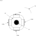
- FIG. 4 is schematic top view of a tire stud according to a preferred embodiment of the present invention, namely the tire stud 11 illustrated in FIG. 3 .
- FIG. 4 only the four foldable wings E,(1), E I (2), E I (3) and E I (4), numbered as 114a, 114b, 114c and 114d, are visible. 19 represents the top of the stud body.
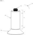
- FIG. 5 is a three-dimensional schematic view of a tire stud according to another preferred embodiment of the present invention.
- the tire stud 21 according to the present invention comprises a stud body 23 comprising at least one polymer as defined in the foregoing, the stud body comprising a top portion P T , an intermediate portion P I and a bottom portion P B .
- the tire stud 21 further comprises a pin 22 which is inserted at the top of 23.
- the tire stud further comprises a foldable anchoring element E B (1), namely a foldable anchoring collar, numbered as 24.
- FIG. 5 shows the tire stud in its pre-insertion/expansion position, namely the collar is unfolded at an angle of more than 100° outward from the stud body.
- the material of the anchoring element is preferably the same material used for the stud body.
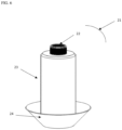
- the anchoring element is at least partially flexible. The tire stud when inserted into a tire tread will then be in its inserted position, wherein the collar is flipped to be in the folded position which is illustrated in FIG. 6 .
Landscapes
- Engineering & Computer Science (AREA)
- Mechanical Engineering (AREA)
- Tires In General (AREA)
Abstract
Description
- The present invention relates to a tire stud comprising a stud body and one or more foldable anchoring elements attached to the stud body. The present invention further relates to a tire, preferably a pneumatic tire, comprising said tire stud and to a method of inserting said tire stud into a tire tread. Such tire stud is of particular value for use on winter, snow and/or ice tires.
- Studs for winter tires have been known for decades and have helped to significantly improve traction characteristics on snow and particularly ice-covered surfaces to improve the grip of the tire to icy roads and other icy pavements. However, conventional tire studs also have some drawbacks which have limited their use in winter tires. For example, conventional tire studs typically have a body which is made of a metal material, such as aluminum, and have a pin extending from the body for ensuring non-skid behavior of the tire on icy roads. Recently studs based on polymeric material have been developed, an example of a polymer stud is given in
U.S. Patent Publication No. 2021/0008930 . - In any case, the use of polymeric material in tire studs is not very well-established and there is still a need for improvement in stud design. In particular, there is always a need to improve stud retention in the tire tread for polymeric stud body. In this regard, with the tire stud of the present invention, it was found that by adapting the design of the polymeric stud body of a tire stud it was possible to improve its durability compared to tire studs known in the art.
- The invention relates to a tire stud in accordance with
claim 1, to a tire in accordance with claim 14 and to a method in accordance with claim 15. - Dependent claims refer to preferred embodiments of the invention.
- In a preferred aspect of the invention, a tire stud is provided comprising a stud body comprising at least one polymer and a pin; wherein the stud body comprises a top portion PT, an intermediate portion PI and a bottom portion PB, PT being adjacent to PI being adjacent to PB; and wherein, in PB, the tire stud further comprises n foldable anchoring elements EB(n), with n = 1 or more, attached to the stud body, wherein each foldable anchoring element extends axially outward, i.e. away, from the stud body.
- Due to the one or more foldable anchoring elements of the tire stud, the tire studs according to the present invention are better retained in the borehole of the tread of the pneumatic tire increasing greatly the durability of the tire stud and their efficacy for winter, snow and/or ice pneumatic tires.
- Furthermore, the present invention relates to a pneumatic tire comprising at least one tire stud according to the present invention.
- In the context of the present invention, the expression "each foldable or bendable anchoring element extends radially outward from the stud body" means that said element extends at an angle > 0°, preferably in the range of from 1° to 170°, more preferably in the range of from 2° to 160°, outward from the stud body.
- In the context of the present invention, the term "inserted position" for the tire stud refers to the position of the tire stud once it is embedded in a pneumatic tire (tread).
- In the context of the present invention, the term "pre-insertion position" or "expansion position" for the tire stud refers to the position of the tire stud as produced and not embedded into a pneumatic tire (tread).
- In the context of the present invention, the term "radial" or "radial direction" refers to a length or distance that is parallel to the axis from the top of the pin of the tire stud to the bottom of the stud body. Hence, the radial direction is parallel to the axis of rotation or to the symmetry axis of the tire stud, if any. "Radial" also refers to the direction when the tire stud is inserted into the tread of a tire, i.e., in accordance with its intended use. Hence, a "radial" direction of the tire stud is also a radial direction of the tire.
- In the context of the present invention, the term "axial" or "axial direction" refers to a length or distance that is perpendicular to the radial direction. "Axial" also refers to the direction when the tire stud is inserted into the tread of a tire, i.e., in accordance with its intended use. Hence, an "axial" direction of the tire stud is also an axial direction of the tire, i.e., parallel to the axis of rotation of the tire.
- The invention will be described by way of example and with reference to the accompanying drawings in which:
-
FIG. 1 is a schematic cross-sectional view of the assembly of a tire stud according to a first embodiment of the present invention into a pneumatic tire tread; -
FIG. 2 is a schematic top view of the tire stud ofFIG. 1 ; -
FIG. 3 is a three-dimensional view of a tire stud according to a second embodiment of the present invention; -
FIG. 4 is a schematic top view of the tire stud ofFIG. 3 ; -
FIG. 5 andFIG. 6 are three-dimensional views of a tire stud according to a third embodiment of the present invention (pre-insertion and inserted positions). - A tire stud is disclosed comprising a stud body comprising at least one polymer and a pin; wherein the stud body comprises a top portion PT, an intermediate portion PI and a bottom portion PB, PT being adjacent to PI being adjacent to PB; and wherein, in PB, the tire stud further comprises n foldable anchoring elements EB(n), with n = 1 or more, attached to the stud body, wherein each foldable anchoring element extends axially outward from the stud body.
- Preferably, each anchoring element is foldable at the junction between said anchoring element and the stud body.
- Preferably, n = 2 or more, such that the tire stud comprises two or more foldable anchoring elements EB(n).
- Preferably, when n = 2 or more, the junction between the anchoring elements and the stud body is located in the upper part of the bottom portion PB of the stud body.
- Preferably, when n = 2 or more, in PB, the foldable anchoring elements are positioned in the same horizontal plan.
- Preferably, n is in the range of from 2 to 10, more preferably in the range of from 2 to 8, more preferably in the range of from 3 to 6.
- Preferably, in PB, the tire stud comprises three foldable anchoring elements EB(1), EB(2) and EB(3) or four foldable anchoring elements EB(1), EB(2), EB(3) and EB(4), which are spaced from one another, more preferably equally spaced from one another.
- Preferably, when n = 2 or more, at least one anchoring element EB(1) of the n foldable anchoring elements EB(n), more preferably each element EB(n), has a length LEB in the range of from 0.25 to 6 mm, more preferably in the range of from 0.5 to 5 mm, more preferably in the range of from 1 to 4 mm, the length LEB being the axial distance between the most outward end point of the element and the end point of the element in contact with the stud body.
- Preferably, when n = 2 or more, one foldable anchoring element, more preferably each of the n foldable anchoring elements EB(n) has a maximal width WEB in the range of from 0.25 to 7 mm, more preferably in the range of from 0.5 to 6 mm, more preferably in the range of from 1 to 4 mm.
- Preferably, when n = 2 or more, the foldable anchoring elements EB(n) have a substantially rectangular shape, substantially triangular shape, half-moon shape or trapezoidal shape, more preferably a substantially rectangular shape.
- Preferably, when n = 2 or more, the n foldable anchoring elements are foldable anchoring wings.
- Preferably, when n = 2 or more, in PI, the tire stud further comprises m foldable anchoring elements EI(m), with m = 2 or more, attached to the stud body, wherein each foldable anchoring element EI(m) extends axially outward from the stud body.
- Preferably, m is in the range of from 2 to 10, more preferably in the range of from 2 to 8, more preferably in the range of from 3 to 6.
- Preferably, in PT, there is no foldable anchoring element.
- Preferably, in PI, there is no foldable anchoring element.
- Alternatively, preferably, in PI, the tire stud comprises three foldable anchoring elements EI(1), EI(2) and EI(3) or four foldable anchoring elements EI(1), EI(2), EI(3) and EI(4) which are spaced from one another, more preferably equally spaced from one another.
- Preferably, in PI, the foldable anchoring elements EI(m) are positioned in the same horizontal plan.
- Preferably, the foldable anchoring elements EI(m) of PI are located in a plan parallel to the plan, wherein the foldable anchoring elements EB(n) of PB are located, with n = 2 or more.
- Preferably, in PI, at least one anchoring element, more preferably each element, of the m foldable anchoring elements EI(m) has a length LEI in the range of from 0.25 to 6 mm, more preferably in the range of from 0.5 to 5 mm, more preferably in the range of from 1 to 4 mm, the length LEI being the axial distance between the most outward end point of the element and the end point of the element in contact with the stud body. Preferably, LEI = LEB.
- Preferably, in PI, one foldable anchoring element, more preferably each element, of the m foldable anchoring elements EI(m) has a maximal width WEI in the range of from 0.25 to 7 mm, more preferably in the range of from 0.5 to 6 mm, more preferably in the range of from 1 to 4 mm. Preferably, WEI = WEB.
- Preferably, in PI, the foldable anchoring elements EI(m) have a substantially rectangular shape, substantially triangular shape, half-moon shape or trapezoidal shape, more preferably a substantially rectangular shape. More preferably, the foldable anchoring elements EI(m) have the same shape as the foldable anchoring elements EB(n).
- Preferably, n = m.
- Preferably, the m foldable anchoring elements EI(m) are foldable anchoring wings.
- In the context of the present invention, preferably, in PB, the foldable anchoring elements EB(n) comprise at least one polymer, more preferably the anchoring elements are made of the same at least one polymer of the stud body.
- Preferably, the foldable anchoring elements EB(n) are at least partially flexible. Preferably, the foldable anchoring elements EI(m) are at least partially flexible.
- Preferably, in PI, the foldable anchoring elements EI(m) comprise at least one polymer, more preferably the anchoring elements are made of the same at least one polymer of the stud body.
- Preferably, all foldable anchoring elements of the tire stud are made of the same material as the material used for the stud body.
- Preferably, the tire stud has an inserted position and a pre-insertion position, wherein, when n = 2 or more, at the inserted position, the foldable anchoring elements are folded and adjacent to the stud body, and, at the pre-insertion position, the foldable anchoring elements are unfolded at an angle, in the range of from 25 to 90°, more preferably in the range of from 35 to 90°, outward from the stud body.
- As an alternative to the above, preferably, n = 1 such that the tire stud comprises one foldable anchoring element EB(1).
- Preferably, when n = 1, the foldable anchoring element is a foldable anchoring collar.
- Preferably, when n = 1, the junction between the anchoring element and the stud body is located in the lower part of the bottom portion PB of the stud body.
- Preferably, the foldable anchoring collar has a maximal width is in the range of from 0.25 to 7 mm, more preferably in the range of from 0.5 to 6 mm, more preferably in the range of from 1 to 4 mm.
- Preferably, the foldable anchoring collar has a regular circular shape or an irregular circular shape. When the collar has an irregular circular shape, it means that it can comprise one or more protrusions. Preferably, the foldable anchoring collar is attached all around the stud body and is foldable at the junction of the stud body and the collar.
- Preferably, the foldable anchoring collar comprises at least one polymer, more preferably the foldable anchoring collar is made of the same at least one polymer of the stud body.
- Preferably, the foldable anchoring collar is at least partially flexible.
- Preferably, the foldable anchoring collar is made of the same material as the material used for the stud body.
- Preferably, the tire stud has an inserted position and a pre-insertion position, wherein, when n = 1, at the inserted position, the foldable anchoring element is folded at an angle in the range of from 10 to 60°, more preferably in the range of from 15 to 50°, outward from the stud body, and, at the pre-insertion position, the foldable anchoring element is unfolded at an angle, of more than 90°, more preferably in the range of from 100 to 170°, more preferably in the range of from 115 to 140°, outward from the stud body.
- In the context of the present invention, the stud body may have any shapes. Examples of shapes are illustrated in the figures of the present invention.
- Preferably, the at least one polymer comprised in the stud body is selected from the group consisting of polyetheretherketone (PEEK), polyphenylene sulfide (PPS), polyphenyl ether (PPE), polypropylene (PP), polyethylene (PE), polycarbonate (PC), polysulfone (PSU), polyetherimide (PEI), polyphenylene sulfone (PPSU), polyarylamide (PARA), polyamine (PA), syndiotactic 1,2-polybutadiene (SPBD), phenolic resin, melamine resin, epoxy resin, benzoxazine-based polymer, cyanate ester resin, polyurethane (PU), polyacrylic ester, a polyimide and a mixture of two or more thereof.
- In the context of the present invention, SPBD offers the advantage of becoming securely bound to the rubber of the tire tread. It is believed that the syndiotactic 1,2-polybutadiene (SPBD) co-cures with the rubber of the tire tread during the curing of the tire, resulting in a strong adhesion between the SPBD and the tire tread. SPBD can be prepared in an inert organic solvent utilizing the technique described in
U.S. Patent No. 3,901,868 or in an aqueous medium utilizing the process described inU.S. Patent No. 4,506,031 . The latter more specifically reveals a process for producing polybutadiene composed essentially of SPBD comprising the steps of: - (A) preparing a catalyst component solution by dissolving, in an inert organic solvent containing 1,3-butadiene
- (1) at least one cobalt compound selected from the group consisting of
- (a) beta-diketone complexes of cobalt,
- (b) beta-keto acid ester complexes of cobalt,
- (c) cobalt salts of organic carboxylic acids having 6 to 15 carbon atoms, and
- (d) complexes of halogenated cobalt compounds of the formula CoXn,
- (2) at least one organoaluminum compound of the formula AIR3,
wherein R represents a hydrocarbon radical of 1 to 6 carbon atoms;
- (1) at least one cobalt compound selected from the group consisting of
- (B) preparing a reaction mixture by mixing said catalyst component solution with a 1,3-butadiene/water mixture containing desired amounts of said 1,3-butadiene;
- (C) preparing a polymerization mixture by mixing carbon disulfide throughout said reaction mixture, and
- (D) polymerizing said 1,3-butadiene in said polymerization mixture into polybutadiene while agitating said polymerization mixture. In the process described therein the crystallinity and melting point of the SPBD can be controlled by adding alcohols, ketones, nitriles, aldehydes or amides to the polymerization mixture.
- Preferably, the SPBD utilized for preparing the stud body comprised in the tire stud of the present invention has a melting point of 160°C or less, more preferably in the range of from 70°C to 160°C, more preferably in the range of from 80°C to 150°C, more preferably in the range of from 90°C to 125°C. The melting points referred to herein are the minimum endotherm values determined from DSC ( differential scanning calorimetry) curves.
- It is conceivable that the stud body comprises a blend of polymers, including SPDB (from 25 to 75 weight - percent based on the weight of the blend) and at least one rubber (from 75 to 25 weight - percent based on the weight of the blend) which is curable with the SPBD. The rubber component used in such blends can be virtually any type of elastomer which contains unsaturation that allows for sulfur curing. Typically, the elastomer will be one or more polydiene rubbers. Some representative examples of suitable polydiene rubbers include cis-1,4-polybutadiene, natural rubber, synthetic polyisoprene, styrene butadiene rubber, EPDM (ethylenepropylene- diene monomer) rubbers, isoprene-butadiene rubbers, and styreneisoprene-butadiene rubbers. In many cases it will be desirable to utilize a combination of diene rubbers in the blend. For instance, the rubber portion of the blend can be a combination of chlorobutyl rubber, natural rubber, and EPDM rubber. Preferably, a the rubber component comprises from 30 to 80 weight - percent, more preferably from 55 to 65 weight - percent, chlorobutyl rubber, from 15 to 55 weight - percent, more preferably from 25 to 45 weight - percent, natural rubber, and from 2 to 10 weight - percent, more preferably from 3 to 7 weight - percent, EPDM, the weight percent being based on the weight of the rubber component.
- In the context of the present invention, it is believed that the inclusion of high content of SPBD in the stud body results in better adhesion, abrasion, and tear resistance for the cured material. High contents of SPBD also result in increased green strength and stiffness. Additionally, it is believed that the use of high levels of SPBD reduces green tack which makes handling. However, the incorporation of large amounts of SPBD into the blend also results in reduced flexibility and modulus. Accordingly, for the best balance of overall properties, the blend utilized preferably contains from 33 to 67 weight - percent SPBD and from 67 to 33 weight - percent co-curable rubbers. More preferably, the blend in the stud body contains from 45 to 55 weight - percent SPBD and from 55 to 45 weight - percent of the elastomeric component.
- The SPBD used for preparing the blend can be in powder or pellet form. The SPBD powder or pellets can be mixed into the rubber component utilizing standard mixing techniques. However, the mixing is normally carried out at a temperature which is at least as high as the melting point of the SPBD being utilized. During the mixing procedure, the SPBD powder pellets are fluxed into the rubber with additional desired compounding ingredients. Such mixing is typically carried out in a Banbury mixer, a mill mixer or in some other suitable type of mixing device.
- Such blends of SPBD and rubber component may further contain other standard rubber chemicals. For instance, such blends may contain sulfur and at least one desired colorant or pigment, e.g. titanium dioxide can be of interest as it can be used as pigment and filler. They will also typically contain other rubber chemicals, such as antioxidants, accelerators, oils, and waxes in conventional amounts. The typical content of sulfur and first and secondary accelerators are disclosed in
U.S. Patent Publication No. 2021/0008930 which is incorporated herein. - Alternatively or in addition to SPBD, other polymers, such as those disclosed in the foregoing, can be used for the stud body.
- Optionally, the stud body is reinforced with one or more fibers. Preferably, the one or more fibers are glass fibers, woven fibers or staple fibers. The stud body may further comprise one or more of a pigment and a dye.
- Preferably, the at least one polymer comprised in the n foldable anchoring elements EB(n) of the tire stud is selected from the group consisting of polyetheretherketone (PEEK), polyphenylene sulfide (PPS), polyphenyl ether (PPE), polypropylene (PP), polyethylene (PE), polycarbonate (PC), polysulfone (PSU), polyetherimide (PEI), polyphenylene sulfone (PPSU), polyarylamide (PARA), polyamine (PA), syndiotactic 1,2-polybutadiene (SPBD), phenolic resin, melamine resin, epoxy resin, benzoxazine-based polymer, cyanate ester resin, polyurethane (PU), polyacrylic ester, a polyimide and a mixture of two or more thereof.
- Preferably, the at least one polymer comprised in the m foldable anchoring elements EI(n) of the tire stud is selected from the group consisting of polyetheretherketone (PEEK), polyphenylene sulfide (PPS), polyphenyl ether (PPE), polypropylene (PP), polyethylene (PE), polycarbonate (PC), polysulfone (PSU), polyetherimide (PEI), polyphenylene sulfone (PPSU), polyarylamide (PARA), polyamine (PA), syndiotactic 1,2-polybutadiene (SPBD), phenolic resin, melamine resin, epoxy resin, benzoxazine-based polymer, cyanate ester resin, polyurethane (PU), polyacrylic ester, a polyimide and a mixture of two or more thereof.
- Optionally, the foldable anchoring element(s) of the tire stud is(are) reinforced with one or more fibers. Preferably, the one or more fibers are glass fibers, woven fibers or staple fibers. The foldable anchoring element(s) of the tire stud may further comprise one or more of a pigment and a dye.
- Preferably, the stud body and the n foldable anchoring elements EB(n) of the tire stud are made of the same material.
- Preferably, the stud body and the m foldable anchoring elements EI(m) of the tire stud are made of the same material.
- Preferably, the stud body and the n foldable anchoring elements are produced in one piece.
- Preferably, the stud body and the n foldable anchoring elements are formed/produced by injection molding or the like. Indeed, thanks to the stiffness and elasticity of the used polymer, the element(s) can be folded and unfolded at the junction stud body/element.
- Preferably, the stud body and any foldable anchoring elements of the tire stud are produced in one piece. Preferably, the stud body and any foldable anchoring elements of the tire stud are formed/produced by injection molding or the like.
- Preferably, the stud body presents one or more constrictions, wherein the width of the stud body in the one or more constriction areas is lower than the width of the stud body in the non-constriction areas.
- Preferably, in the intermediate portion PI, the stud body presents one or more constrictions, wherein the width of the stud body in the one or more constriction areas is lower than the width of the stud body in the non-constriction areas.
- Preferably, the stud body presents one constriction.
- Alternatively, preferably, the stud body presents a constriction at the upper part of PI and a constriction at the lower part of PI with a bead between said constrictions. This is in particular illustrated in
FIG. 3 . - Preferably, in PI, the tire stud further comprises m foldable anchoring elements EI(m), with m = 2 or more, attached to the stud body, wherein each of said foldable anchoring elements extend axially, i.e. away, outward from the stud body.
- Preferably, the width of the bead is equal to from 95 to 105 percent, more preferably from 98 to 102 percent, more preferably from 99 to 101 percent, of the maximal width of the stud body in the top portion.
- Preferably, the width of the bead is equal to from 95 to 105 percent, more preferably from 98 to 102 percent, more preferably from 99 to 101 percent, of the maximal width of the stud body in the bottom portion.
- Preferably, in PI, the foldable anchoring elements EI(m) are attached to the bead of the stud body.
- Preferably, the foldable anchoring elements EI(m) in PI are as defined in the foregoing.
- Alternatively, preferably, the stud body presents no constriction. This is in particular illustrated in
FIG. 1 ,5 and6 , wherein there is also no anchoring elements in PI and PT. - In the context of the present invention, it is preferred that the top portion PT, the intermediate portion PI and the bottom portion PB of the stud body have the same or different shapes.
- The present invention further relates to a pneumatic tire comprising at least one tire stud according to the present invention.
- Preferably, the pneumatic tire further comprises a tread, wherein the tread comprises the at least one tire stud, more preferably a plurality of tire studs according to the present invention, embedded therein. The pin comprised in the at least one stud extends out of the tread.
- Preferably, the pneumatic tire is a winter, snow and/or ice pneumatic tire.
- The present invention is further illustrated by the following set of embodiments and combinations of embodiments resulting from the dependencies and back-references as indicated. In particular, it is noted that in each instance where a range of embodiments is mentioned, for example in the context of a term such as "The tire stud of any one of
embodiments 1 to 3", every embodiment in this range is meant to be explicitly disclosed for the skilled person, i.e. the wording of this term is to be understood by the skilled person as being synonymous to "The tire stud of any one ofembodiments - According to
embodiment 1 of the present invention relating to a tire stud, the tire stud comprises - a stud body comprising at least one polymer;
- a pin;
- wherein the stud body comprises a top portion PT, an intermediate portion PI and a bottom portion PB, PT being adjacent to PI being adjacent to PB,
- wherein, in PB, the tire stud further comprises n foldable anchoring elements EB(n), with n = 1 or more, attached to the stud body, wherein each foldable anchoring element extends axially outward, i.e. away, from the stud body.
- The tire stud of
embodiment 1, wherein each anchoring element is foldable at the junction between said anchoring element and the stud body. - The tire stud of
embodiment - The tire stud of any one of
embodiments 1 to 3, wherein, when n = 2 or more, at least one anchoring element EB(1) of the n foldable anchoring elements WB(n), preferably each element EB(n), has a length LEB in the range of from 0.25 to 6 mm, preferably in the range of from 0.5 to 5 mm, more preferably in the range of from 1 to 4 mm, the length LEB being the axial distance between the most outward end point of the element and the end point of the element in contact with the stud body. - The tire stud of any one of
embodiments 1 to 4, wherein, when n = 2 or more, one foldable anchoring element, preferably each, of the n foldable anchoring elements EB(n) has a maximal width WEB in the range of from 0.25 to 7 mm, preferably in the range of from 0.5 to 6 mm, more preferably in the range of from 1 to 4 mm. - The tire stud of any one of
embodiments 1 to 5, wherein, when n = 2 or more, the foldable anchoring element EB(n) have a substantially rectangular shape, substantially triangular shape, half-moon shape, or trapezoidal shape, preferably a substantially rectangular shape. - The tire stud of any one of
embodiments 1 to 6, wherein, when n = 2 or more, the n foldable anchoring elements are foldable anchoring wings. - The tire stud of any one of
embodiments 1 to 7, wherein, when n = 2 or more, in PI, the tire stud further comprises m foldable anchoring elements EI(m), with m = 2 or more, attached to the stud body, wherein each foldable anchoring element EI(m) extends axially outward away from the stud body. - The tire stud of embodiment 8, wherein, in PI, the tire stud comprises three foldable anchoring elements EI(1), EI(2) and EI(3) or four foldable anchoring elements EI(1), EI(2), EI(3) and EI(4) which are spaced from one another, preferably equally spaced from one another.
- The tire stud of any one of
embodiments 1 to 9, wherein, in PB, the foldable anchoring elements comprise at least one polymer, preferably the anchoring elements are made of the same at least one polymer of the stud body. - The tire stud of any one of
embodiments 1 to 10, wherein the tire stud has an inserted position and a pre-insertion position, wherein, when n = 2 or more, at the inserted position, the foldable anchoring elements are folded and adjacent to the stud body and, at the pre-insertion position, the foldable anchoring elements are unfolded at an angle, in the range of from 25 to 90°, preferably in the range of from 35 to 90°, outward from the stud body. - The tire stud of any one of
embodiments 1 to 11, wherein, when n = 1, the foldable anchoring element is a foldable anchoring collar, preferably wherein the tire stud has an inserted position and a pre-insertion position, wherein, when n = 1, at the inserted position, the foldable anchoring element is folded at an angle in the range of from 10 to 60°, more preferably in the range of from 15 to 50°, outward from the stud body, and, at the pre-insertion position, the foldable anchoring element is unfolded at an angle, of more than 90°, more preferably in the range of from 100 to 170 °, more preferably in the range of from 115 to 140°, outward from the stud body. - The tire stud of any one of
embodiments 1 to 12, wherein the at least one polymer comprised in the stud body is selected from the group consisting of polyetheretherketone (PEEK), polyphenylene sulfide (PPS), polyphenyl ether (PPE), polypropylene (PP), polyethylene (PE), polycarbonate (PC), polysulfone (PSU), polyetherimide (PEI), polyphenylene sulfone (PPSU), polyarylamide (PARA), polyamine (PA), syndiotactic 1,2-polybutadiene (SPBD), phenolic resin, melamine resin, epoxy resin, benzoxazine-based polymer, cyanate ester resin, polyurethane (PU), polyacrylic ester, a polyimide and a mixture of two or more thereof. - The tire stud of any one of
embodiments 1 to 13, wherein the stud body and the n foldable anchoring elements are produced in one piece, preferably by injection molding. - The tire stud of any one of
embodiments 1 to 14, wherein, in the intermediate portion PI, the stud body presents one or more constrictions, wherein the width of the stud body in the one or more constriction areas is lower than the width of the stud body in the non-constriction areas. - The tire stud of embodiment 15, wherein the stud body presents a constriction at the upper part of PI and a constriction at the lower part of PI with a bead between said constrictions, wherein, in PI, the tire stud further comprises m foldable anchoring elements WI(m), with m = 2 or more, attached to the stud body, wherein each of said foldable anchoring elements extend axially outward, i.e. away, from the stud body.
- The tire stud of any one of
embodiments 1 to 14, wherein the stud body presents no constriction. - A pneumatic tire comprising at least one tire stud according to any one of
embodiments 1 to 17. - The pneumatic tire of
embodiment 18, further comprising a tread, wherein the tread comprises the at least one tire stud, more preferably a plurality of tire studs according to any one ofembodiments 1 to 17, embedded therein, wherein the pin comprised in the at least one stud extends out of the tread. - The pneumatic tire of
embodiment -
FIG. 1 is a schematic cross-sectional view of the assembly of a tire stud according to a preferred embodiment of the present invention into a pneumatic tire tread. In particular,FIG. 1 shows thetire stud 1 according to the present invention in different positions A, B and C during its assembly into a pneumatic tire tread 5. Position A is the pre-insertion or expansion position, at which the anchoring wings EB(1), EB(2) numbered as 4 a and 4b are unfolded at an angle of about 90° outward from the stud body. Position B is the pre-insertion or expansion position, at which the anchoring wings are unfolded at an angle of about 30° outward from the stud body and position C is the inserted position at which the anchoring wings EB(1), EB(2) numbered as 4a, 4b are folded and adjacent to the stud body and thetire stud 1 is in the tread 5, with thepin 2 extending out of the tread 5. Thetire stud 1 comprises astud body 3 comprising at least one polymer as defined in the foregoing, the stud body comprising a top portion PT, an intermediate portion PI and a bottom portion PB. Thetire stud 1 further comprises apin 2 which is inserted at the top of 3. In PB, thetire stud 1 further comprises three foldable anchoring wings EB(1), EB(2) numbered as 4a, 4b and 4c and EB(3) not shown inFIG. 1 which have the same dimensions and are spaced equally from one another in the same horizontal plan. The material of the wings is preferably the same material used for the stud body. -
FIG. 2 is a schematic top view of a tire stud according to a preferred embodiment of the present invention, namely thetire stud 1 illustrated inFIG. 1 . InFIG. 2 , the three foldable wings EB(1), EB(2) and EB(3), numbered as 4a, 4b and 4c, are visible. -
FIG. 3 is a three-dimensional schematic view of a tire stud according to another preferred embodiment of the present invention. Thetire stud 11 according to the present invention comprises astud body 13 comprising at least one polymer as defined in the foregoing, the stud body comprising a top portion PT, an intermediate portion PI and a bottom portion PB. Thetire stud 11 further comprises apin 12 which is inserted at the top of 13. In PB, thetire stud 11 further comprises four foldable anchoring wings EB(1), EB(2), EB(3) and EB(4), numbered as 14a, 14b, 14c and 14d, which have the same dimensions and are spaced equally from one another in the same horizontal plan. The material of the wings EB(1), EB(2), EB(3) and EB(4) is preferably the same material used for the stud body. In PI, the stud body comprises twoconstrictions bead 18 between said constrictions and four foldable anchoring wings EI(1), EI(2), EI(3) and EI(4), numbered as 114a, 114b, 114c and 114d.FIG. 3 shows the tire stud in a pre-insertion position. -
FIG. 4 is schematic top view of a tire stud according to a preferred embodiment of the present invention, namely thetire stud 11 illustrated inFIG. 3 . InFIG. 4 , only the four foldable wings E,(1), EI(2), EI(3) and EI(4), numbered as 114a, 114b, 114c and 114d, are visible. 19 represents the top of the stud body. -
FIG. 5 is a three-dimensional schematic view of a tire stud according to another preferred embodiment of the present invention. Thetire stud 21 according to the present invention comprises astud body 23 comprising at least one polymer as defined in the foregoing, the stud body comprising a top portion PT, an intermediate portion PI and a bottom portion PB. Thetire stud 21 further comprises apin 22 which is inserted at the top of 23. In PB, the tire stud further comprises a foldable anchoring element EB(1), namely a foldable anchoring collar, numbered as 24.FIG. 5 shows the tire stud in its pre-insertion/expansion position, namely the collar is unfolded at an angle of more than 100° outward from the stud body. The material of the anchoring element is preferably the same material used for the stud body. The anchoring element is at least partially flexible. The tire stud when inserted into a tire tread will then be in its inserted position, wherein the collar is flipped to be in the folded position which is illustrated inFIG. 6 .
Claims (15)
- A tire stud, the tire stud (1) having a stud body (3) comprising or consisting of at least one polymer and a pin (2), wherein the stud body (3) comprises a radially outer top portion (PT), an intermediate portion (PI) and a radially inward bottom portion (PB), the outer portion (PT) being radially adjacent the intermediate portion (PI) and the intermediate portion (PI) being adjacent to the inward bottom portion (PB), and wherein, in the radially inward bottom portion (PB), the tire stud (1) further comprises at least one foldable or bendable anchoring element (4a, 4b, 4c) attached to the stud body (3), said anchoring element (4a, 4b, 4c) extending away from the stud body (3).
- The tire stud of claim 1, wherein each anchoring element (4a, 4b, 4c) is foldable or bendable at the junction between said anchoring element (4a, 4b, 4c) and the stud body (3).
- The tire stud of claim 1 or 2, wherein the tire stud (1) comprises three or four of said anchoring elements (4a, 4b, 4c), said anchoring elements (4a, 4b, 4c) being preferably radially spaced from one another and/or said anchoring elements (4a, 4b, 4c) being preferably spaced circumferentially around the stud body (3) from one another.
- The tire stud of at least one of the previous claims, wherein, when there are at least two or more such anchoring elements (4a, 4b, 4c), at least one anchoring element (4a, 4b, 4c) of said anchoring elements (4a, 4b, 4c) has a length in the range of from 0.25 to 6 mm, preferably of from 0.5 mm to 3 mm, said length being the axial distance between the axially most outward end point of the respective anchoring element (4a, 4b, 4c) and the axially inner end point of the anchoring element (4a, 4b, 4c) in contact with the stud body (3).
- The tire stud of at least one of the previous claims, wherein, when viewed in top view along the axis from the radially outer top portion (PT) to the radially inward bottom portion (PB) onto the anchoring element (4a, 4b, 4c), the anchoring element (4a, 4b, 4c) has a substantially rectangular shape, substantially triangular shape, a substantially half-moon shape, a wing shape or a substantially trapezoidal shape.
- The tire stud of at least one of the previous claims, wherein the tire stud (1) further comprises at least one foldable or bendable further anchoring element (114a, 114b, 114c, 114d) attached to the stud body (3), wherein said further anchoring element (114a, 114b, 114c, 114d) extends away from the stud body (3) and is attached to the stud body (3) in the intermediate portion (PI), and, optionally, wherein each further anchoring element (114a, 114b, 114c, 114d) is foldable or bendable at the junction between said further anchoring element (114a, 114b, 114c, 114d) and the stud body (3).
- The tire stud of claim 6 , wherein the tire stud (1) comprises three or four of said further anchoring elements (114a, 114b, 114c, 114d), said further anchoring elements (114a, 114b, 114c, 114d) being preferably radially spaced from one another and/or said further anchoring elements (114a, 114b, 114c, 114d) being preferably spaced circumferentially around the stud body (3) from one another.
- The tire stud of at least one of the previous claims, wherein said anchoring elements (4a, 4b, 4c) and/or said further anchoring elements (114a, 114b, 114c, 114d) comprise or consist of at least one polymer.
- The tire stud of at least one of the previous claims, wherein said anchoring element (4a, 4b, 4c) and/or said further anchoring element (114a, 114b, 114c, 114d) is a foldable or bendable anchoring collar extending about the stud body (3).
- The tire stud of at least one of the previous claims, wherein the at least one polymer of the stud body (3) is selected from the group consisting of polyetheretherketone (PEEK), polyphenylene sulfide (PPS), polyphenols ether (PPE), polypropylene (PP), polyethylene (PE), polycarbonate (PC), polysulfone (PSU), polyetherimide (PEI), polyphenylene sulfone (PPSU), polyarylamide (PARA), polyamine (PA), syndiotactic 1,2-polybutadiene (SPBD), phenolic resin, melamine resin, epoxy resin, benzoxazine-based polymer, cyanate ester resin, polyurethane (PU), polyacrylic ester, a polyimide and a mixture of two or more thereof.
- The tire stud of at least one of the previous claims, wherein, in the intermediate portion (PI), the stud body (3) presents one or more constriction areas (16, 17), said one or more constriction areas (16, 17) preferably extending circumferentially around the intermediate portion (PI) of the stud body (3), the axial width of the stud body (3) in the one or more constriction areas (16, 17) being lower than the axial width of the stud body (3) in the non-constriction areas of the intermediate portion (PI).
- The tire stud of 11, wherein the stud body (3) presents a first constriction area (16) at a radially upper part of the intermediate portion (PI), a second constriction area (17) at a radially lower part of the intermediate portion (PI), and a bead (18) or rim radially between said constrictions areas (16, 17).
- The tire stud of at least one of the previous claims, wherein the stud body (3) and the anchoring elements (4a, 4b, 4c) and/or the further anchoring elements (114a, 114b, 114c, 114d) are integrally formed as one piece.
- A tire having a tread, wherein the tread comprises at least one tire stud (1) in according with at least one of the previous claims, and wherein the tire stud (1) is inserted in the tread and the pin (2) extends radially out of the surface of the tread.
- A method of inserting a tire stud in according with at least one of the previous claims 1 to 14 into a tread of a tire, the method comprising:(i) providing the tire stud (1) with the anchoring the anchoring elements (4a, 4b, 4c) and/or the further anchoring elements (114a, 114b, 114c, 114d) being in a pre-insertion position and extending at an angle in the range of from 15° to 90° or from 25° to 90° with respect to the radial direction away from the stud body (3); and(ii) inserting the tire stud (1) in the tire tread and bringing the anchoring elements (4a, 4b, 4c) and/or the further anchoring elements (114a, 114b, 114c, 114d) in an insertion position being folded or bent and adjacent to the stud body (3) or extending at an angle in the range of from 0° to 10°with respect to the radial direction away from the stud body (3).
Applications Claiming Priority (1)
| Application Number | Priority Date | Filing Date | Title |
|---|---|---|---|
| US202218057445A | 2022-11-21 | 2022-11-21 |
Publications (2)
| Publication Number | Publication Date |
|---|---|
| EP4371788A1 true EP4371788A1 (en) | 2024-05-22 |
| EP4371788B1 EP4371788B1 (en) | 2025-07-02 |
Family
ID=88839881
Family Applications (1)
| Application Number | Title | Priority Date | Filing Date |
|---|---|---|---|
| EP23210506.4A Active EP4371788B1 (en) | 2022-11-21 | 2023-11-17 | Tire stud with anchoring elements |
Country Status (2)
| Country | Link |
|---|---|
| EP (1) | EP4371788B1 (en) |
| FI (1) | FI4371788T3 (en) |
Citations (6)
| Publication number | Priority date | Publication date | Assignee | Title |
|---|---|---|---|---|
| US3901868A (en) | 1973-09-27 | 1975-08-26 | Ube Industries | Process for producing butadiene polymers |
| US4506031A (en) | 1982-09-17 | 1985-03-19 | The Goodyear Tire & Rubber Company | Microencapsulated aqueous polymerization catalyst |
| KR20100052186A (en) * | 2008-11-10 | 2010-05-19 | 한국타이어 주식회사 | Stud pin structure of stud tire |
| DE102011089314A1 (en) * | 2010-12-21 | 2012-06-21 | The Yokohama Rubber Co., Ltd. | Pneumatic tire and spike |
| DE102015219368A1 (en) * | 2014-10-09 | 2016-04-14 | Toyo Tire & Rubber Co., Ltd. | Spike and studded tires |
| US20210008930A1 (en) | 2019-07-08 | 2021-01-14 | The Goodyear Tire & Rubber Company | Polymer stud and a tire comprising a polymer stud |
-
2023
- 2023-11-17 FI FIEP23210506.4T patent/FI4371788T3/en active
- 2023-11-17 EP EP23210506.4A patent/EP4371788B1/en active Active
Patent Citations (6)
| Publication number | Priority date | Publication date | Assignee | Title |
|---|---|---|---|---|
| US3901868A (en) | 1973-09-27 | 1975-08-26 | Ube Industries | Process for producing butadiene polymers |
| US4506031A (en) | 1982-09-17 | 1985-03-19 | The Goodyear Tire & Rubber Company | Microencapsulated aqueous polymerization catalyst |
| KR20100052186A (en) * | 2008-11-10 | 2010-05-19 | 한국타이어 주식회사 | Stud pin structure of stud tire |
| DE102011089314A1 (en) * | 2010-12-21 | 2012-06-21 | The Yokohama Rubber Co., Ltd. | Pneumatic tire and spike |
| DE102015219368A1 (en) * | 2014-10-09 | 2016-04-14 | Toyo Tire & Rubber Co., Ltd. | Spike and studded tires |
| US20210008930A1 (en) | 2019-07-08 | 2021-01-14 | The Goodyear Tire & Rubber Company | Polymer stud and a tire comprising a polymer stud |
Also Published As
| Publication number | Publication date |
|---|---|
| FI4371788T3 (en) | 2025-09-26 |
| EP4371788B1 (en) | 2025-07-02 |
Similar Documents
| Publication | Publication Date | Title |
|---|---|---|
| EP0445486B1 (en) | Polypropylene reinforced rubber | |
| EP0941871B1 (en) | Tire with carcass ply rubber composition | |
| EP3763549B1 (en) | A polymer stud and a tire comprising a polymer stud | |
| US10286729B2 (en) | Tire having crack resistant sidewalls | |
| JP5892298B1 (en) | Stud tire | |
| DE69917853T2 (en) | Anti-reversion agent for use in run-flat tires | |
| JPH11321252A (en) | Tire with sidewall carcass reinforcement | |
| US8439095B2 (en) | Tire having tread with an internal softer transition rubber layer containing short fiber reinforcement | |
| US8247487B2 (en) | Tire with tread containing carboxylated styrene/butadiene rubber | |
| JP3790462B2 (en) | Tire using apex rubber compound containing in situ generated resin | |
| US7735533B2 (en) | Heavy duty tire with silica-rich polyisoprene rubber based intermediate transition layer | |
| EP4371788B1 (en) | Tire stud with anchoring elements | |
| US5023292A (en) | Tire compounds | |
| CN102639622A (en) | Mix for producing tyres with improved rolling resistance | |
| EP4375090B1 (en) | Tire stud and tire comprising such a tire stud | |
| JP2009143561A (en) | Pneumatic tire with inner liner containing low melting polyamide | |
| US5885389A (en) | Tire with chafer composition | |
| EP4686584A1 (en) | Tire stud and tire | |
| CN114867812A (en) | Sealant material composition | |
| US6011093A (en) | Tire tread rubber containing uintahite | |
| WO2016106416A1 (en) | Epoxidized rubber compositions | |
| JP2003041057A (en) | Rubber composition for tire | |
| EP1810847A1 (en) | Tire with silica-rich polyisoprene rubber based intermediate transition layer | |
| JP7332876B2 (en) | sealant composition | |
| MXPA99002474A (en) | Rim with reinforcement in the side wall of the carc |
Legal Events
| Date | Code | Title | Description |
|---|---|---|---|
| PUAI | Public reference made under article 153(3) epc to a published international application that has entered the european phase |
Free format text: ORIGINAL CODE: 0009012 |
|
| STAA | Information on the status of an ep patent application or granted ep patent |
Free format text: STATUS: THE APPLICATION HAS BEEN PUBLISHED |
|
| AK | Designated contracting states |
Kind code of ref document: A1 Designated state(s): AL AT BE BG CH CY CZ DE DK EE ES FI FR GB GR HR HU IE IS IT LI LT LU LV MC ME MK MT NL NO PL PT RO RS SE SI SK SM TR |
|
| STAA | Information on the status of an ep patent application or granted ep patent |
Free format text: STATUS: REQUEST FOR EXAMINATION WAS MADE |
|
| 17P | Request for examination filed |
Effective date: 20241122 |
|
| RBV | Designated contracting states (corrected) |
Designated state(s): AL AT BE BG CH CY CZ DE DK EE ES FI FR GB GR HR HU IE IS IT LI LT LU LV MC ME MK MT NL NO PL PT RO RS SE SI SK SM TR |
|
| GRAP | Despatch of communication of intention to grant a patent |
Free format text: ORIGINAL CODE: EPIDOSNIGR1 |
|
| STAA | Information on the status of an ep patent application or granted ep patent |
Free format text: STATUS: GRANT OF PATENT IS INTENDED |
|
| RIC1 | Information provided on ipc code assigned before grant |
Ipc: B60C 11/16 20060101AFI20250120BHEP |
|
| INTG | Intention to grant announced |
Effective date: 20250131 |
|
| GRAS | Grant fee paid |
Free format text: ORIGINAL CODE: EPIDOSNIGR3 |
|
| GRAA | (expected) grant |
Free format text: ORIGINAL CODE: 0009210 |
|
| STAA | Information on the status of an ep patent application or granted ep patent |
Free format text: STATUS: THE PATENT HAS BEEN GRANTED |
|
| AK | Designated contracting states |
Kind code of ref document: B1 Designated state(s): AL AT BE BG CH CY CZ DE DK EE ES FI FR GB GR HR HU IE IS IT LI LT LU LV MC ME MK MT NL NO PL PT RO RS SE SI SK SM TR |
|
| REG | Reference to a national code |
Ref country code: GB Ref legal event code: FG4D |
|
| REG | Reference to a national code |
Ref country code: CH Ref legal event code: EP |
|
| REG | Reference to a national code |
Ref country code: DE Ref legal event code: R096 Ref document number: 602023004519 Country of ref document: DE |
|
| REG | Reference to a national code |
Ref country code: IE Ref legal event code: FG4D |
|
| REG | Reference to a national code |
Ref country code: FI Ref legal event code: FGE |
|
| REG | Reference to a national code |
Ref country code: SE Ref legal event code: TRGR |
|
| REG | Reference to a national code |
Ref country code: NL Ref legal event code: MP Effective date: 20250702 |
|
| PG25 | Lapsed in a contracting state [announced via postgrant information from national office to epo] |
Ref country code: PT Free format text: LAPSE BECAUSE OF FAILURE TO SUBMIT A TRANSLATION OF THE DESCRIPTION OR TO PAY THE FEE WITHIN THE PRESCRIBED TIME-LIMIT Effective date: 20251103 |
|
| PG25 | Lapsed in a contracting state [announced via postgrant information from national office to epo] |
Ref country code: NL Free format text: LAPSE BECAUSE OF FAILURE TO SUBMIT A TRANSLATION OF THE DESCRIPTION OR TO PAY THE FEE WITHIN THE PRESCRIBED TIME-LIMIT Effective date: 20250702 |
|
| REG | Reference to a national code |
Ref country code: AT Ref legal event code: MK05 Ref document number: 1808847 Country of ref document: AT Kind code of ref document: T Effective date: 20250702 |
|
| PG25 | Lapsed in a contracting state [announced via postgrant information from national office to epo] |
Ref country code: IS Free format text: LAPSE BECAUSE OF FAILURE TO SUBMIT A TRANSLATION OF THE DESCRIPTION OR TO PAY THE FEE WITHIN THE PRESCRIBED TIME-LIMIT Effective date: 20251102 |
|
| PGFP | Annual fee paid to national office [announced via postgrant information from national office to epo] |
Ref country code: DE Payment date: 20251022 Year of fee payment: 3 |
|
| PG25 | Lapsed in a contracting state [announced via postgrant information from national office to epo] |
Ref country code: NO Free format text: LAPSE BECAUSE OF FAILURE TO SUBMIT A TRANSLATION OF THE DESCRIPTION OR TO PAY THE FEE WITHIN THE PRESCRIBED TIME-LIMIT Effective date: 20251002 |
|
| REG | Reference to a national code |
Ref country code: LT Ref legal event code: MG9D |
|
| PG25 | Lapsed in a contracting state [announced via postgrant information from national office to epo] |
Ref country code: AT Free format text: LAPSE BECAUSE OF FAILURE TO SUBMIT A TRANSLATION OF THE DESCRIPTION OR TO PAY THE FEE WITHIN THE PRESCRIBED TIME-LIMIT Effective date: 20250702 |
|
| PGFP | Annual fee paid to national office [announced via postgrant information from national office to epo] |
Ref country code: FI Payment date: 20251022 Year of fee payment: 3 |
|
| PG25 | Lapsed in a contracting state [announced via postgrant information from national office to epo] |
Ref country code: HR Free format text: LAPSE BECAUSE OF FAILURE TO SUBMIT A TRANSLATION OF THE DESCRIPTION OR TO PAY THE FEE WITHIN THE PRESCRIBED TIME-LIMIT Effective date: 20250702 |
|
| PGFP | Annual fee paid to national office [announced via postgrant information from national office to epo] |
Ref country code: FR Payment date: 20251022 Year of fee payment: 3 |
|
| PG25 | Lapsed in a contracting state [announced via postgrant information from national office to epo] |
Ref country code: GR Free format text: LAPSE BECAUSE OF FAILURE TO SUBMIT A TRANSLATION OF THE DESCRIPTION OR TO PAY THE FEE WITHIN THE PRESCRIBED TIME-LIMIT Effective date: 20251003 |
|
| PGFP | Annual fee paid to national office [announced via postgrant information from national office to epo] |
Ref country code: SE Payment date: 20251022 Year of fee payment: 3 |
|
| PG25 | Lapsed in a contracting state [announced via postgrant information from national office to epo] |
Ref country code: CZ Free format text: LAPSE BECAUSE OF FAILURE TO SUBMIT A TRANSLATION OF THE DESCRIPTION OR TO PAY THE FEE WITHIN THE PRESCRIBED TIME-LIMIT Effective date: 20250702 |
|
| PG25 | Lapsed in a contracting state [announced via postgrant information from national office to epo] |
Ref country code: LV Free format text: LAPSE BECAUSE OF FAILURE TO SUBMIT A TRANSLATION OF THE DESCRIPTION OR TO PAY THE FEE WITHIN THE PRESCRIBED TIME-LIMIT Effective date: 20250702 |
|
| PG25 | Lapsed in a contracting state [announced via postgrant information from national office to epo] |
Ref country code: BG Free format text: LAPSE BECAUSE OF FAILURE TO SUBMIT A TRANSLATION OF THE DESCRIPTION OR TO PAY THE FEE WITHIN THE PRESCRIBED TIME-LIMIT Effective date: 20250702 Ref country code: PL Free format text: LAPSE BECAUSE OF FAILURE TO SUBMIT A TRANSLATION OF THE DESCRIPTION OR TO PAY THE FEE WITHIN THE PRESCRIBED TIME-LIMIT Effective date: 20250702 |
|
| PG25 | Lapsed in a contracting state [announced via postgrant information from national office to epo] |
Ref country code: RS Free format text: LAPSE BECAUSE OF FAILURE TO SUBMIT A TRANSLATION OF THE DESCRIPTION OR TO PAY THE FEE WITHIN THE PRESCRIBED TIME-LIMIT Effective date: 20251002 |
|
| PG25 | Lapsed in a contracting state [announced via postgrant information from national office to epo] |
Ref country code: ES Free format text: LAPSE BECAUSE OF FAILURE TO SUBMIT A TRANSLATION OF THE DESCRIPTION OR TO PAY THE FEE WITHIN THE PRESCRIBED TIME-LIMIT Effective date: 20250702 |
|
| PG25 | Lapsed in a contracting state [announced via postgrant information from national office to epo] |
Ref country code: RO Free format text: LAPSE BECAUSE OF FAILURE TO SUBMIT A TRANSLATION OF THE DESCRIPTION OR TO PAY THE FEE WITHIN THE PRESCRIBED TIME-LIMIT Effective date: 20250702 |
|
| PG25 | Lapsed in a contracting state [announced via postgrant information from national office to epo] |
Ref country code: SM Free format text: LAPSE BECAUSE OF FAILURE TO SUBMIT A TRANSLATION OF THE DESCRIPTION OR TO PAY THE FEE WITHIN THE PRESCRIBED TIME-LIMIT Effective date: 20250702 |
|
| REG | Reference to a national code |
Ref country code: DE Ref legal event code: R097 Ref document number: 602023004519 Country of ref document: DE |
|
| PG25 | Lapsed in a contracting state [announced via postgrant information from national office to epo] |
Ref country code: DK Free format text: LAPSE BECAUSE OF FAILURE TO SUBMIT A TRANSLATION OF THE DESCRIPTION OR TO PAY THE FEE WITHIN THE PRESCRIBED TIME-LIMIT Effective date: 20250702 |
|
| PG25 | Lapsed in a contracting state [announced via postgrant information from national office to epo] |
Ref country code: IT Free format text: LAPSE BECAUSE OF FAILURE TO SUBMIT A TRANSLATION OF THE DESCRIPTION OR TO PAY THE FEE WITHIN THE PRESCRIBED TIME-LIMIT Effective date: 20250702 |
|
| PG25 | Lapsed in a contracting state [announced via postgrant information from national office to epo] |
Ref country code: EE Free format text: LAPSE BECAUSE OF FAILURE TO SUBMIT A TRANSLATION OF THE DESCRIPTION OR TO PAY THE FEE WITHIN THE PRESCRIBED TIME-LIMIT Effective date: 20250702 Ref country code: SK Free format text: LAPSE BECAUSE OF FAILURE TO SUBMIT A TRANSLATION OF THE DESCRIPTION OR TO PAY THE FEE WITHIN THE PRESCRIBED TIME-LIMIT Effective date: 20250702 |
|
| PLBE | No opposition filed within time limit |
Free format text: ORIGINAL CODE: 0009261 |
|
| STAA | Information on the status of an ep patent application or granted ep patent |
Free format text: STATUS: NO OPPOSITION FILED WITHIN TIME LIMIT |
|
| REG | Reference to a national code |
Ref country code: CH Ref legal event code: L10 Free format text: ST27 STATUS EVENT CODE: U-0-0-L10-L00 (AS PROVIDED BY THE NATIONAL OFFICE) Effective date: 20260518 |
|
| 26N | No opposition filed |
Effective date: 20260407 |
|
| PG25 | Lapsed in a contracting state [announced via postgrant information from national office to epo] |
Ref country code: LT Free format text: LAPSE BECAUSE OF FAILURE TO SUBMIT A TRANSLATION OF THE DESCRIPTION OR TO PAY THE FEE WITHIN THE PRESCRIBED TIME-LIMIT Effective date: 20250702 Ref country code: MC Free format text: LAPSE BECAUSE OF FAILURE TO SUBMIT A TRANSLATION OF THE DESCRIPTION OR TO PAY THE FEE WITHIN THE PRESCRIBED TIME-LIMIT Effective date: 20250702 |
|
| PG25 | Lapsed in a contracting state [announced via postgrant information from national office to epo] |
Ref country code: LU Free format text: LAPSE BECAUSE OF NON-PAYMENT OF DUE FEES Effective date: 20251117 |