EP4371752A1 - Production method of a pneumatic tire with a selant layer and tire obtained thereby - Google Patents
Production method of a pneumatic tire with a selant layer and tire obtained thereby Download PDFInfo
- Publication number
- EP4371752A1 EP4371752A1 EP23195960.2A EP23195960A EP4371752A1 EP 4371752 A1 EP4371752 A1 EP 4371752A1 EP 23195960 A EP23195960 A EP 23195960A EP 4371752 A1 EP4371752 A1 EP 4371752A1
- Authority
- EP
- European Patent Office
- Prior art keywords
- tire
- circling
- sealant material
- width direction
- sealant
- Prior art date
- Legal status (The legal status is an assumption and is not a legal conclusion. Google has not performed a legal analysis and makes no representation as to the accuracy of the status listed.)
- Pending
Links
Images


Classifications
-
- B—PERFORMING OPERATIONS; TRANSPORTING
- B29—WORKING OF PLASTICS; WORKING OF SUBSTANCES IN A PLASTIC STATE IN GENERAL
- B29D—PRODUCING PARTICULAR ARTICLES FROM PLASTICS OR FROM SUBSTANCES IN A PLASTIC STATE
- B29D30/00—Producing pneumatic or solid tyres or parts thereof
- B29D30/06—Pneumatic tyres or parts thereof (e.g. produced by casting, moulding, compression moulding, injection moulding, centrifugal casting)
- B29D30/0681—Parts of pneumatic tyres; accessories, auxiliary operations
- B29D30/0685—Incorporating auto-repairing or self-sealing arrangements or agents on or into tyres
-
- B—PERFORMING OPERATIONS; TRANSPORTING
- B29—WORKING OF PLASTICS; WORKING OF SUBSTANCES IN A PLASTIC STATE IN GENERAL
- B29D—PRODUCING PARTICULAR ARTICLES FROM PLASTICS OR FROM SUBSTANCES IN A PLASTIC STATE
- B29D30/00—Producing pneumatic or solid tyres or parts thereof
- B29D30/0061—Accessories, details or auxiliary operations not otherwise provided for
- B29D2030/0066—Tyre quality control during manufacturing
-
- B—PERFORMING OPERATIONS; TRANSPORTING
- B29—WORKING OF PLASTICS; WORKING OF SUBSTANCES IN A PLASTIC STATE IN GENERAL
- B29D—PRODUCING PARTICULAR ARTICLES FROM PLASTICS OR FROM SUBSTANCES IN A PLASTIC STATE
- B29D30/00—Producing pneumatic or solid tyres or parts thereof
- B29D30/06—Pneumatic tyres or parts thereof (e.g. produced by casting, moulding, compression moulding, injection moulding, centrifugal casting)
- B29D30/0601—Vulcanising tyres; Vulcanising presses for tyres
- B29D30/0633—After-treatment specially adapted for vulcanising tyres
- B29D2030/0634—Measuring, calculating, correcting tyre uniformity, e.g. correcting RFV
-
- B—PERFORMING OPERATIONS; TRANSPORTING
- B29—WORKING OF PLASTICS; WORKING OF SUBSTANCES IN A PLASTIC STATE IN GENERAL
- B29D—PRODUCING PARTICULAR ARTICLES FROM PLASTICS OR FROM SUBSTANCES IN A PLASTIC STATE
- B29D30/00—Producing pneumatic or solid tyres or parts thereof
- B29D30/06—Pneumatic tyres or parts thereof (e.g. produced by casting, moulding, compression moulding, injection moulding, centrifugal casting)
- B29D30/0681—Parts of pneumatic tyres; accessories, auxiliary operations
- B29D30/0685—Incorporating auto-repairing or self-sealing arrangements or agents on or into tyres
- B29D2030/0686—Incorporating sealants on or into tyres not otherwise provided for; auxiliary operations therefore, e.g. preparation of the tyre
-
- B—PERFORMING OPERATIONS; TRANSPORTING
- B29—WORKING OF PLASTICS; WORKING OF SUBSTANCES IN A PLASTIC STATE IN GENERAL
- B29D—PRODUCING PARTICULAR ARTICLES FROM PLASTICS OR FROM SUBSTANCES IN A PLASTIC STATE
- B29D30/00—Producing pneumatic or solid tyres or parts thereof
- B29D30/06—Pneumatic tyres or parts thereof (e.g. produced by casting, moulding, compression moulding, injection moulding, centrifugal casting)
- B29D30/0681—Parts of pneumatic tyres; accessories, auxiliary operations
- B29D30/0685—Incorporating auto-repairing or self-sealing arrangements or agents on or into tyres
- B29D2030/0686—Incorporating sealants on or into tyres not otherwise provided for; auxiliary operations therefore, e.g. preparation of the tyre
- B29D2030/0694—Incorporating sealants on or into tyres not otherwise provided for; auxiliary operations therefore, e.g. preparation of the tyre the sealant being in the form of one or more narrow strips, e.g. applied by winding into the interior of the tyre
Definitions
- Patent Document 1 discloses a pneumatic tire in which a sealant layer is formed by coating a sealant material of substantially cord-like shape in a spiral shape continuously along the tire inner surface.
- the present invention has an object of providing a pneumatic tire and production method thereof which can improve the uniformity of a pneumatic tire equipped with a sealant layer on the tire inner surface.
- a pneumatic tire according to the present invention includes: a tire having a light point; and a sealant layer provided to an inner surface of the tire, in which the sealant layer has a belt-like sealant material circling along a tire-circumferential direction on the inner surface of the tire, and a plurality of annular circling parts extending in the tire-circumferential direction arranged in parallel in the tire-width direction, by a path of circling thereof transitioning to one side in the tire-width direction at least every one turn, a circling part arranged most to one end side in the tire-width direction among the plurality of circling parts has a winding start of the sealant material, and a circling part arranged most to another end side in the tire-width direction has a winding end of the sealant material, a tire-circumferential direction position of each of the winding start and the winding end corresponds to a tire-circumferential direction position of the light point, and a sealant material increasing
- Fig. 1 is a side view of a tire 1 produced by a production method according to the embodiment.
- G in Fig. 1 shows a rotational axis line, which is a center of rotation of the tire 1 extending in a paper plane front/back direction of Fig. 1.
- Fig. 1 shows a circumferential direction of the tire 1 by the arrow R.
- Fig. 2 is a view schematically showing a tire-width direction cross-sectional view of the tire 1.
- the tire 1 according to an example is a pneumatic tire mounted to a rim (not shown) in which the internal pressure is filled by air or the like at the inner cavity thereof.
- the tire 1 according to the embodiment is a tire for a passenger vehicle.
- the production method of the tire according to the embodiment is applicable to a production method of a tire for various vehicles such as light trucks, trucks and buses.
- the pair of beads 10 constitute a tire-radial direction inside portion of the tire 1.
- the bead 10 includes high modulus rubber.
- the bead 10 includes an annular bead core 11 made by covering a plurality of wound bead wires made of metal with rubber.
- the bead core 11 plays the role of fixing the tire 1 to the rim.
- the tread 20 includes belts 21, and tread rubber 25 arranged at the outer side in the tire-radial direction of the belts 21.
- the tread rubber 25 has a contact surface 25a which makes contact with the road surface.
- a plurality of main grooves 26 extending in the circumferential direction are formed in the contact surface 25a.
- the belt 21 is a member reinforcing the tread 20.
- the belt 21 of the embodiment is a two-layer structure including an inside belt 22, and outside belt 23 arranged on the outer side in the tire-radial direction of the inside belt 22.
- the inside belt 22 and outside belt 23 both have a structure in which belt cords such as a plurality of steel cords are covered with rubber.
- the inside belt 22 is larger in tire-width direction length than the outside belt 23. Therefore, each of the ends 21A on both sides in the tire-width direction of the belt 21 is configured by an end in the tire-width direction of the inside belt 22.
- the outside belt 23 may be larger in tire-width direction length than the inside belt 22.
- the belt 21 may be a single layer structure, or may be a structure of three or more layers.
- the sidewall 30 includes sidewall rubber 31 which constitutes a side wall surface on the outer side of the tire 1.
- the sidewall rubber 31 bends the most upon the tire 1 making a cushion action, and normally is configured by flexible rubber having fatigue resistance.
- a carcass ply constituting a ply serving as the backbone of the tire 1 is embedded inside of the tire 1.
- This carcass ply is embedded inside of the tire 1, in a mode passing between the pair of bead cores 11, the pair of sidewalls 30 and the tread 20.
- This carcass ply for example, has a configuration in which the plurality of ply cords consisting of an insulative organic fiber cord such as polyester or polyamide, or the like are covered by rubber.
- the above-mentioned belt 21 is arranged on the outer side in the tire-radial direction of this carcass ply.
- Fig. 2 a carcass ply constituting a ply serving as the backbone of the tire 1 is embedded inside of the tire 1.
- This carcass ply is embedded inside of the tire 1, in a mode passing between the pair of bead cores 11, the pair of sidewalls 30 and the tread 20.
- This carcass ply for example, has a configuration in which the plurality
- the tire 1 according to the present embodiment further includes a sealant layer 60.
- the sealant layer 60 is arranged over the entire circumference in the tire-circumferential direction, in a region of the tire inner cavity surface configured by the inner liner corresponding at least to the tread 20.
- the length in the tire-width direction of the sealant layer 60 is larger than the contact surface 25a of the tread 20, and both ends 60A in the tire-width direction of the sealant layer 60 are preferably positioned more to the outer side in the tire-width direction than both ends in the tire-width direction of the contact surface 25a.
- the length in the tire-width direction of the sealant layer 60 is shorter than the length in the tire-width direction of the belt 21, and each of both ends 60A in the tire-width direction of the sealant layer 60 is preferably positioned more to the inner side in the tire-width direction than both ends 21A in the tire-width direction of the belt 21.
- the sealant layer 60 is formed by a belt-like sealant material being wound along the tire-circumferential direction on the tire inner surface.
- the sealant material a material having stickiness is favorably used, and is pasted to the tire inner cavity surface by the stickiness thereof.
- the thickness of the sealant layer 60 of at least 2 mm is said to be favorable.
- a production method of a tire according to an embodiment for producing the tire 1 equipped with the above configuration will be explained below.
- the production method of a tire according to the embodiment relates to a method of forming the above-mentioned sealant layer 60 on the tire 1 obtained by vulcanizing a green tire, which is the source article of the tire 1 molded so as to be the above-mentioned configuration.
- Static unbalance refers to a mass unbalance in the circumferential direction during tire non-rotation, the position of maximum weight in the circumferential direction is referred to as the static unbalance position, and the mass thereof is referred to as static unbalance amount.
- the static unbalance for example, occurs due to variation in the members themselves constituting the tire, deformation of members during molding and during vulcanization of the green tire, etc.
- Occasional unbalance refers to the mass unbalance at the near side or far side of both sides of the tire during tire non-rotation, for example, and occurs due to eccentricity of a member during tire molding, eccentricity of the green tire or vulcanizing mold, or the like.
- Dynamic unbalance is the imbalance in the mass during tire rotation, produced by static unbalance and occasional unbalance being combined by rotating, and the mass thereof is referred to as dynamic unbalance amount.
- the dynamic unbalance position and dynamic unbalance amount are respectively measured on the front side and back side of both side surfaces of the tire.
- Fig. 3 is a flowchart showing a production method according to the embodiment in process order.
- a static unbalance position measurement step of measuring the static unbalance is performed (Step S1).
- a light-point ascertaining step of ascertaining the light point K of the tire 1 shown in Fig. 1 is performed (Step S2).
- the position of the light point of the tire 1 is the position 180° in the circumferential direction relative to the static unbalance position, and is the lightest position in the circumferential direction 180° to the opposite side relative to the heaviest static unbalance position.
- Step S3 a dynamic unbalance position measurement step of measuring the dynamic unbalance position of the tire 1 is performed.
- Step S4 a dynamic unbalance compensation position ascertaining step of ascertaining the position at which dynamic unbalance of the tire 1 is to be compensated is performed. From the above, the tire-circumferential direction position which can compensate static unbalance and the position which can compensate dynamic unbalance are ascertained within the tire 1.
- Step S5 the sealant layer 60 is formed by sealant material application on the tire inner surface.
- Step S6 a dynamic unbalance compensation sealant material arrangement step of arranging a dynamic unbalance compensation sealant material 65 at the ascertained dynamic unbalance compensation position is performed.
- Fig. 4 is a view showing an example of a method specifically implementing Step S5, and is an exploded view showing a part in the circumferential direction of a tire inner surface to which the sealant material 61 is pasted and the sealant layer 60 is formed.
- Fig. 4 indicates the tire-circumferential direction by R, and indicates the tire-width direction by X.
- the sealant layer 60 is formed by one belt-like sealant material 61 which is pasted while being wound along the tire-circumferential direction on the tire inner surface.
- the sealant layer 60 has a plurality of annular circling parts 62 and plurality of transition parts 63 formed by the sealant material 61.
- the sealant layer 60 is formed by applying the belt-like sealant material 61 on the entire circumference of the application region in the tire-width direction of the sealant material 61 on the tire inner surface, while being wound around along the tire-circumferential direction, and while transitioning the path of this circling to a side of one direction (right direction in Fig. 4 ) of the tire-width direction every one turn.
- the annular circling parts 62 are arranged in parallel in the tire-width direction by a plurality of sealant material 61 extending in the tire-circumferential direction.
- the sealant material 61 may be pasted to the tire inner surface while transitioning to the tire-width direction every one turn; however, it may be pasted to overlap for two turns or three turns at the same location in the tire-width direction.
- the reference symbol 61A indicates the winding start of the sealant material 61
- the reference symbol 61B indicates the winding end of the sealant material 61.
- the sealant material 61 is continuously pasted from one end side to the other end side (left side to right side in Fig. 4 ) in the tire-width direction, while winding around as shown by the arrow F, from the winding start 61A to the winding end 61B.
- the winding start 61A and winding end 61B are both set at positions where the circumferential-direction position thereof corresponds to the circumferential-direction position of the light point K. In other words, at each of the winding start 61A and winding end 61B and the light point K, the tire-circumferential direction positions are the same.
- the circling part 62 is formed by the sealant material 61 being pasted on the tire inner surface in parallel with the tire-circumferential direction.
- the plurality of circling parts 62 are arranged in parallel so as to be adjacent in a state close to each other in the tire-width direction.
- the plurality of transition parts 63 slope with a predetermined angle relative to the tire-circumferential direction, and are arranged in parallel so as to be adjacent in a state close to each other.
- the transition parts 63 are provided aligned at predetermined positions in the tire-circumferential direction.
- the transition part 63 is a portion at which the sealant material 61 transitions to one side in the tire-width direction (right side in Fig. 4 ), after one circling part 62 is formed by the sealant material 61 being pasted for about one turn on the tire inner surface.
- the next circling part 62 is pasted, through the transition part 63, to be adjacent at one side in the tire-width direction of the pasted circling part 62.
- the next circling part 62 adjacent on one side in the tire-width direction is repeatedly formed via the transition part 63, whereby the sealant layer 60 is formed.
- step pasting Upon pasting the sealant material 61 to the tire inner surface in this way, the pasting method of sequentially arranging and pasting in the tire-width direction the circling parts 62 parallel in the tire-circumferential direction while passing through the transition parts 63 may be referred to as step pasting below.
- the sealant material 61 for example, it is possible to use a sealing member having stickiness made by blending a plasticizer such as polyisobutylene and polybutene, a tackifier such as a thermoplastic olefin/diolefin copolymer, and a filler such as carbon black and silica, into unvulcanized or semi-vulcanized butyl rubber, for example.
- a plasticizer such as polyisobutylene and polybutene
- a tackifier such as a thermoplastic olefin/diolefin copolymer
- a filler such as carbon black and silica
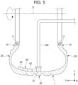
- Fig. 5 is a view schematically showing an example of a method of applying the sealant material 61 to the tire inner surface in the step pasting.
- a width-direction cross section of the tire 1 is shown, and the tire-width direction X, tire-radial direction Y and tire-circumferential direction R are respectively shown.
- step paste the sealant material 61 it is possible to perform by discharging and coating the sealant material 61 onto the inner surface of the tire 1, from the nozzle 100, while rotating the tire 1 around the axis line G, and moving the nozzle 100 in the tire-width direction, as shown in Fig. 5 .
- the nozzle 100 is attached to the leading end of an extruder (not shown), and is inserted to the inner side of the tire 1.
- the sealant material 61 extruded from this extruder is discharged and coated on the inner surface of the tire 1 from the leading end of the nozzle 100.
- One circling part 62 is coated by rotating the tire 1 approximately one time in a state stopping movement in the tire-width direction, while discharging the sealant material 61 continuously from the nozzle 100, and while continuously rotating the tire 1 around its axis.
- the transition part 63 is coated meanwhile.
- the movement in the tire-width direction is stopped, and the circling part 62 next to the previously coated circling part 62 is coated.
- sealant material 61 When coating and pasting the sealant material 61 to the entirety of the formation area of the sealant layer 60, discharge of sealant material 61 from the nozzle 100 stops.
- the sealant layer 60 is formed by the sealant material 61 in this way.
- the cross-sectional shape of the sealant material 61 discharged from the nozzle 100 and pasted on the tire inner surface is preferably a substantially rectangular shape. It is thereby possible to equalize the thickness as the sealant layer 60.
- the adjacent circling parts 62 are in close contact with each other in the tire-width direction, and a gap hardly occurs between the circling parts 62.
- the initial circling part 62A on one end side in the tire-width direction (left side in Fig. 4 ) formed first among the plurality of circling parts 62 has a first sealant material increasing part 62A1 which overlaps in the tire-thickness direction at the transition part 63 from the initial circling part 62A to the next circling part 62, as shown in Fig. 4 .
- the finishing circling part 62B on the other end side in the tire-width direction (right side in Fig.
- the fourth ) formed last has a second sealant material increasing part 62B1 which overlaps in the tire-thickness direction with the transition part 63 transitioning to the finishing circling part 62B.
- the first sealant material increasing part 62A1 is a triangular portion at which the transition part 63 overlaps over the winding start 61A.
- the second sealant material increasing part 62B1 is a triangular portion at which the winding end 61B overlaps over the transition part 63.
- the winding start 61A and winding end 61B are both arranged at positions corresponding to the light point K in the tire-circumferential direction. Therefore, the first sealant material increasing part 62A1 and second sealant material increasing part 62B1 provided at this winding start 61A and winding end 61B are both arranged at positions corresponding to the light point K in the tire-circumferential direction.
- the first sealant material increasing part 62A1 and second sealant material increasing part 62B1 are arranged at the position of the light point K serving as a counter relative to the heaviest static unbalance position in the tire-circumferential direction. It thereby becomes possible for the non-uniform state of weight balance in the circumferential direction of the tire 1 to be compensated, to improve the uniformity relative to static unbalance.
- the dynamic unbalance compensation sealant material 65 is arranged at the ascertained dynamic unbalance compensation position as shown in Fig. 4 .
- the dynamic unbalance compensation sealant material 65 a fragment made by cutting the belt-like sealant material 61 to the required length can be used.
- the dynamic unbalance compensation sealant material 65 is pasted at the position approaching one side in the tire-width direction of the sealant layer 60 on the tire inner surface.
- this hole is automatically plugged by the sealant layer 60, and the puncture is prevented before it happens.
- a dynamic unbalance position measuring step of measuring a dynamic unbalance position of the tire 1 it is preferable for a dynamic unbalance position measuring step of measuring a dynamic unbalance position of the tire 1 to be performed together with the static unbalance position measuring step, and the method to further include: a dynamic unbalance compensation position ascertaining step of ascertaining a position at which dynamic unbalance of the tire 1 is compensated, based on the dynamic unbalance position thus measured; and a dynamic unbalance compensation sealant material arranging step of partially arranging the sealant material 61 at the dynamic unbalance compensation position thus ascertained.
- a pneumatic tire includes: a tire 1 having a light point K; and a sealant layer 60 provided to an inner surface of the tire 1, in which the sealant layer 60 has a belt-like sealant material 61 circling along a tire-circumferential direction on the inner surface of the tire 1, and a plurality of annular circling parts 62 extending in the tire-circumferential direction arranged in parallel in the tire-width direction, by a path of circling thereof transitioning to one side in the tire-width direction at least every one turn, a circling part 62 arranged most to one end side in the tire-width direction among the plurality of circling parts 62 has a winding start 61A of the sealant material 61, and a circling part 62 arranged most to another end side in the tire-width direction has a winding end 61B of the sealant material 61, a tire-circumferential direction position of each of the winding start 61A and the winding
Landscapes
- Engineering & Computer Science (AREA)
- Mechanical Engineering (AREA)
- Tires In General (AREA)
- Tyre Moulding (AREA)
Abstract
A pneumatic tire and a production method thereof are provided which can improve the uniformity of a pneumatic tire equipped with a sealant layer at the tire inner surface. Provided are: a static unbalance position measuring step; a light point ascertaining step ; and a sealant layer forming step of providing a sealant layer 60 arranging in parallel in a tire-width direction a plurality of annular circling parts 62 , by coating sealant material 61, while circling along the tire-circumferential direction and while transitioning a path of circling to one direction side in the tire-width direction at least every one circling, in which the sealant layer forming step disposes a winding start 61A and a winding end 61B at a tire-circumferential direction position corresponding to the light point K, in which sealant material increasing parts 62A1, 62B1 are respectively arranged at the winding start 61A and the winding end 61B.
Description
- This application is based on and claims the benefit of priority from
Japanese Patent Application No. 2022-182445, filed on 15 November 2022 - The present invention relates to a pneumatic tire and a production method thereof.
- Conventionally, a pneumatic tire has been known which is equipped with a puncture prevention function whereby a hole in the tire formed during puncture is automatically plugged by a sealant layer provided to the tire inner surface. For example,
Patent Document 1 discloses a pneumatic tire in which a sealant layer is formed by coating a sealant material of substantially cord-like shape in a spiral shape continuously along the tire inner surface. - Patent Document 1:
Japanese Unexamined Patent Application, Publication No.2016-78817 - However, favorable uniformity is generally demanded in tires. In the case of pneumatic tires in which a sealant layer is arranged on the tire inner surface, there is a possibility of this sealant layer impacting uniformity.
- The present invention has an object of providing a pneumatic tire and production method thereof which can improve the uniformity of a pneumatic tire equipped with a sealant layer on the tire inner surface.
- A method of producing a pneumatic tire according to the present invention includes: a static unbalance position measuring step of measuring a static unbalance position of a tire; a light point ascertaining step of ascertaining a light point of the tire based on a static unbalance position thus measured; and a sealant layer forming step of providing a sealant layer arranging in parallel in a tire-width direction a plurality of annular circling parts of sealant material extending in a tire-circumferential direction, by coating belt-like sealant material on an inner surface of the tire, while circling along the tire-circumferential direction and while transitioning a path of circling to one direction side in the tire-width direction at least every one circling, in which the sealant layer forming step disposes each of a winding start and a winding end of the sealant material circling an inner surface of the tire at a tire-circumferential direction position corresponding to the light point, wherein sealant material increasing parts are respectively arranged at the winding start and the winding end.
- A pneumatic tire according to the present invention includes: a tire having a light point; and a sealant layer provided to an inner surface of the tire, in which the sealant layer has a belt-like sealant material circling along a tire-circumferential direction on the inner surface of the tire, and a plurality of annular circling parts extending in the tire-circumferential direction arranged in parallel in the tire-width direction, by a path of circling thereof transitioning to one side in the tire-width direction at least every one turn, a circling part arranged most to one end side in the tire-width direction among the plurality of circling parts has a winding start of the sealant material, and a circling part arranged most to another end side in the tire-width direction has a winding end of the sealant material, a tire-circumferential direction position of each of the winding start and the winding end corresponds to a tire-circumferential direction position of the light point, and a sealant material increasing part is arranged at each of the winding start and the winding end.
- According to the present invention, it is possible to provide a pneumatic tire and a production method thereof which can improve the uniformity of a pneumatic tire equipped with a sealant layer on the tire inner surface.
-
-
Fig. 1 is a side view of a tire according to an embodiment; -
Fig. 2 is a tire-width direction cross-sectional view of the tire; -
Fig. 3 is a flowchart showing a production method according to an embodiment; -
Fig. 4 is an expanded view showing an inner surface of a tire according to an embodiment, which schematically shows a sealant layer; and -
Fig. 5 is a view schematically showing an example of a method of coating a sealant material onto a tire inner surface, upon producing a tire according to the embodiment. - Hereinafter, an embodiment will be explained while referencing the drawings.
Fig. 1 is a side view of atire 1 produced by a production method according to the embodiment. G inFig. 1 shows a rotational axis line, which is a center of rotation of thetire 1 extending in a paper plane front/back direction ofFig. 1. Fig. 1 shows a circumferential direction of thetire 1 by the arrow R.Fig. 2 is a view schematically showing a tire-width direction cross-sectional view of thetire 1. Thetire 1 according to an example is a pneumatic tire mounted to a rim (not shown) in which the internal pressure is filled by air or the like at the inner cavity thereof. Thetire 1 according to the embodiment is a tire for a passenger vehicle. It should be noted that the production method of the tire according to the embodiment is applicable to a production method of a tire for various vehicles such as light trucks, trucks and buses. - The internal structure of the
tire 1 will be briefly explained byFig. 2. Fig. 2 shows a cross section of thetire 1 having a left/right symmetrical structure in a direction extending in the rotation axis line G shown inFig. 1 . The cross-sectional view ofFig. 2 shows the state of thetire 1 in an unloaded state mounting thetire 1 to a standard rim (not shown), and filled with standard internal pressure. - In
Fig. 2 , the symbol S1 is the tire equatorial plane orthogonal to the rotation axis line G.Fig. 2 shows the tire-width direction and tire-radial direction as referenced in the present disclosure by arrows X and Y, respectively. Tire-width direction (arrow X direction) is a direction parallel to the rotation axis line G, and is the left/right direction in the paper plane of the cross-sectional view ofFig. 2 . Tire-width direction inner side is a direction approaching the tire equatorial plane S1, and is the paper-plane central side inFig. 2 . Tire-width direction outer side is a direction distancing from the tire equatorial plane S1, and is the paper-plane left side and right side inFig. 2 . Tire-radial direction (arrow Y direction) is a direction perpendicular to the rotational axis line G, and is the paper-plane up/down direction inFig. 2 .Fig. 1 shows a tire-radial direction Y. Tire-radial direction outer side is a direction distancing from the rotation axis line G, and is the paper-plane upper side inFig. 2 . Tire-radial direction inner side is a direction approaching the rotation axis line G, and is the paper-plane lower side inFig. 2 . - The
tire 1 includes a pair ofbeads 10 provided on both sides in the tire-width direction,tread 20 forming a contact surface with the road surface, and a pair ofsidewalls 30 extending between the pair ofbeads 10 and thetread 20. - The pair of
beads 10 constitute a tire-radial direction inside portion of thetire 1. In order to raise the rigidity of this portion, thebead 10 includes high modulus rubber. Thebead 10 includes anannular bead core 11 made by covering a plurality of wound bead wires made of metal with rubber. Thebead core 11 plays the role of fixing thetire 1 to the rim. - The
tread 20 includes belts 21, and tread rubber 25 arranged at the outer side in the tire-radial direction of the belts 21. The tread rubber 25 has acontact surface 25a which makes contact with the road surface. A plurality ofmain grooves 26 extending in the circumferential direction are formed in thecontact surface 25a. - The belt 21 is a member reinforcing the
tread 20. The belt 21 of the embodiment is a two-layer structure including an inside belt 22, and outside belt 23 arranged on the outer side in the tire-radial direction of the inside belt 22. The inside belt 22 and outside belt 23 both have a structure in which belt cords such as a plurality of steel cords are covered with rubber. The inside belt 22 is larger in tire-width direction length than the outside belt 23. Therefore, each of theends 21A on both sides in the tire-width direction of the belt 21 is configured by an end in the tire-width direction of the inside belt 22. It should be noted the outside belt 23 may be larger in tire-width direction length than the inside belt 22. Furthermore, the belt 21 may be a single layer structure, or may be a structure of three or more layers. - The
sidewall 30 includessidewall rubber 31 which constitutes a side wall surface on the outer side of thetire 1. Thesidewall rubber 31 bends the most upon thetire 1 making a cushion action, and normally is configured by flexible rubber having fatigue resistance. - Although omitted from
Fig. 2 , a carcass ply constituting a ply serving as the backbone of thetire 1 is embedded inside of thetire 1. This carcass ply is embedded inside of thetire 1, in a mode passing between the pair ofbead cores 11, the pair ofsidewalls 30 and thetread 20. This carcass ply, for example, has a configuration in which the plurality of ply cords consisting of an insulative organic fiber cord such as polyester or polyamide, or the like are covered by rubber. The above-mentioned belt 21 is arranged on the outer side in the tire-radial direction of this carcass ply. In addition, although omitted fromFig. 2 , the inner liner as the rubber layer constituting the inner wall surface of thetire 1 is provided spanning between the pair of beads, at the tire inner cavity side of the carcass ply. This inner liner is configured by air permeation resistant rubber, whereby the air inside the tire inner cavity is prevented from leaking to outside. - As shown in
Fig. 2 , thetire 1 according to the present embodiment further includes asealant layer 60. Thesealant layer 60 is arranged over the entire circumference in the tire-circumferential direction, in a region of the tire inner cavity surface configured by the inner liner corresponding at least to thetread 20. The length in the tire-width direction of thesealant layer 60 is larger than thecontact surface 25a of thetread 20, and bothends 60A in the tire-width direction of thesealant layer 60 are preferably positioned more to the outer side in the tire-width direction than both ends in the tire-width direction of thecontact surface 25a. In addition, the length in the tire-width direction of thesealant layer 60 is shorter than the length in the tire-width direction of the belt 21, and each of bothends 60A in the tire-width direction of thesealant layer 60 is preferably positioned more to the inner side in the tire-width direction than bothends 21A in the tire-width direction of the belt 21. Thesealant layer 60 is formed by a belt-like sealant material being wound along the tire-circumferential direction on the tire inner surface. As the sealant material, a material having stickiness is favorably used, and is pasted to the tire inner cavity surface by the stickiness thereof. The thickness of thesealant layer 60 of at least 2 mm is said to be favorable. - A production method of a tire according to an embodiment for producing the
tire 1 equipped with the above configuration will be explained below. The production method of a tire according to the embodiment relates to a method of forming the above-mentionedsealant layer 60 on thetire 1 obtained by vulcanizing a green tire, which is the source article of thetire 1 molded so as to be the above-mentioned configuration. - It should be noted that, herein, "static unbalance position", "static unbalance amount", "dynamic unbalance position" and "dynamic unbalance amount", which are requisites necessary upon implementing the production method of the tire according to the embodiment, will be explained first. Generally, in a pneumatic tire, the uniformity produced by mass unevenness of the tire is roughly divided, and can be exemplified by the three types of static unbalance, occasional unbalance and dynamic unbalance. These types of uniformity, for example, are measured in a product inspection process in the production process.
- Static unbalance refers to a mass unbalance in the circumferential direction during tire non-rotation, the position of maximum weight in the circumferential direction is referred to as the static unbalance position, and the mass thereof is referred to as static unbalance amount. The static unbalance, for example, occurs due to variation in the members themselves constituting the tire, deformation of members during molding and during vulcanization of the green tire, etc. Occasional unbalance refers to the mass unbalance at the near side or far side of both sides of the tire during tire non-rotation, for example, and occurs due to eccentricity of a member during tire molding, eccentricity of the green tire or vulcanizing mold, or the like. Dynamic unbalance is the imbalance in the mass during tire rotation, produced by static unbalance and occasional unbalance being combined by rotating, and the mass thereof is referred to as dynamic unbalance amount. The dynamic unbalance position and dynamic unbalance amount are respectively measured on the front side and back side of both side surfaces of the tire.
-
Fig. 3 is a flowchart showing a production method according to the embodiment in process order. As shown inFig. 3 , as a production method of a tire of the embodiment, first, a static unbalance position measurement step of measuring the static unbalance is performed (Step S1). Next, based on the measured static unbalance position, a light-point ascertaining step of ascertaining the light point K of thetire 1 shown inFig. 1 is performed (Step S2). The position of the light point of thetire 1 is the position 180° in the circumferential direction relative to the static unbalance position, and is the lightest position in the circumferential direction 180° to the opposite side relative to the heaviest static unbalance position. Therefore, at this light point K, when the weight of a predetermined mass serving as a counter relative to the static unbalance amount is arranged, static unbalance is compensated, and an improvement in the mass balance in the tire-circumferential direction is achieved. Next, a dynamic unbalance position measurement step of measuring the dynamic unbalance position of thetire 1 is performed (Step S3). Next, based on the measured dynamic unbalance position, a dynamic unbalance compensation position ascertaining step of ascertaining the position at which dynamic unbalance of thetire 1 is to be compensated is performed (Step S4). From the above, the tire-circumferential direction position which can compensate static unbalance and the position which can compensate dynamic unbalance are ascertained within thetire 1. - Next, the
sealant layer 60 is formed by sealant material application on the tire inner surface (Step S5). Next, a dynamic unbalance compensation sealant material arrangement step of arranging a dynamic unbalancecompensation sealant material 65 at the ascertained dynamic unbalance compensation position is performed (Step S6). -
Fig. 4 is a view showing an example of a method specifically implementing Step S5, and is an exploded view showing a part in the circumferential direction of a tire inner surface to which thesealant material 61 is pasted and thesealant layer 60 is formed.Fig. 4 indicates the tire-circumferential direction by R, and indicates the tire-width direction by X. As shown inFig. 4 , thesealant layer 60 is formed by one belt-like sealant material 61 which is pasted while being wound along the tire-circumferential direction on the tire inner surface. Thesealant layer 60 has a plurality of annular circlingparts 62 and plurality oftransition parts 63 formed by thesealant material 61. - The
sealant layer 60 is formed by applying the belt-like sealant material 61 on the entire circumference of the application region in the tire-width direction of thesealant material 61 on the tire inner surface, while being wound around along the tire-circumferential direction, and while transitioning the path of this circling to a side of one direction (right direction inFig. 4 ) of the tire-width direction every one turn. The annular circlingparts 62 are arranged in parallel in the tire-width direction by a plurality ofsealant material 61 extending in the tire-circumferential direction. It should be noted that thesealant material 61 may be pasted to the tire inner surface while transitioning to the tire-width direction every one turn; however, it may be pasted to overlap for two turns or three turns at the same location in the tire-width direction. - In
Fig. 4 , thereference symbol 61A indicates the winding start of thesealant material 61, and thereference symbol 61B indicates the winding end of thesealant material 61. Thesealant material 61 is continuously pasted from one end side to the other end side (left side to right side inFig. 4 ) in the tire-width direction, while winding around as shown by the arrow F, from the windingstart 61A to the windingend 61B. The windingstart 61A and windingend 61B are both set at positions where the circumferential-direction position thereof corresponds to the circumferential-direction position of the light point K. In other words, at each of the windingstart 61A and windingend 61B and the light point K, the tire-circumferential direction positions are the same. - The circling
part 62 is formed by thesealant material 61 being pasted on the tire inner surface in parallel with the tire-circumferential direction. The plurality of circlingparts 62 are arranged in parallel so as to be adjacent in a state close to each other in the tire-width direction. The plurality oftransition parts 63 slope with a predetermined angle relative to the tire-circumferential direction, and are arranged in parallel so as to be adjacent in a state close to each other. - The
transition parts 63 are provided aligned at predetermined positions in the tire-circumferential direction. Thetransition part 63 is a portion at which thesealant material 61 transitions to one side in the tire-width direction (right side inFig. 4 ), after one circlingpart 62 is formed by thesealant material 61 being pasted for about one turn on the tire inner surface. The next circlingpart 62 is pasted, through thetransition part 63, to be adjacent at one side in the tire-width direction of the pasted circlingpart 62. The next circlingpart 62 adjacent on one side in the tire-width direction is repeatedly formed via thetransition part 63, whereby thesealant layer 60 is formed. Upon pasting thesealant material 61 to the tire inner surface in this way, the pasting method of sequentially arranging and pasting in the tire-width direction the circlingparts 62 parallel in the tire-circumferential direction while passing through thetransition parts 63 may be referred to as step pasting below. - As the
sealant material 61, for example, it is possible to use a sealing member having stickiness made by blending a plasticizer such as polyisobutylene and polybutene, a tackifier such as a thermoplastic olefin/diolefin copolymer, and a filler such as carbon black and silica, into unvulcanized or semi-vulcanized butyl rubber, for example. It should be noted that, not limiting thereto, thesealant material 61 may be another known sealing member that is being used conventionally. In addition, it is preferable to include a characteristic of the fluidity being low and hardly flowing even during high-speed running. -
Fig. 5 is a view schematically showing an example of a method of applying thesealant material 61 to the tire inner surface in the step pasting. InFig. 5 , a width-direction cross section of thetire 1 is shown, and the tire-width direction X, tire-radial direction Y and tire-circumferential direction R are respectively shown. To step paste thesealant material 61, it is possible to perform by discharging and coating thesealant material 61 onto the inner surface of thetire 1, from thenozzle 100, while rotating thetire 1 around the axis line G, and moving thenozzle 100 in the tire-width direction, as shown inFig. 5 . Thenozzle 100 is attached to the leading end of an extruder (not shown), and is inserted to the inner side of thetire 1. Thesealant material 61 extruded from this extruder is discharged and coated on the inner surface of thetire 1 from the leading end of thenozzle 100. - One circling
part 62 is coated by rotating thetire 1 approximately one time in a state stopping movement in the tire-width direction, while discharging thesealant material 61 continuously from thenozzle 100, and while continuously rotating thetire 1 around its axis. Next, when moving thenozzle 100 to one side in the tire-width direction by the width of thesealant material 61, thetransition part 63 is coated meanwhile. Next, the movement in the tire-width direction is stopped, and the circlingpart 62 next to the previously coated circlingpart 62 is coated. By repeating the above operation, it is possible to step paste thesealant material 61 onto the formation area of thesealant layer 60. When coating and pasting thesealant material 61 to the entirety of the formation area of thesealant layer 60, discharge ofsealant material 61 from thenozzle 100 stops. Thesealant layer 60 is formed by thesealant material 61 in this way. Upon step pasting, it is preferable to determine the windingstart 61A so that the coating amount does not vary at the left side and right side of the tire-width direction center. - It should be noted that, as shown in
Fig. 5 , the cross-sectional shape of thesealant material 61 discharged from thenozzle 100 and pasted on the tire inner surface is preferably a substantially rectangular shape. It is thereby possible to equalize the thickness as thesealant layer 60. In addition, the adjacent circlingparts 62 are in close contact with each other in the tire-width direction, and a gap hardly occurs between the circlingparts 62. - In the case of the
sealant material 61 being step pasted to the tire inner surface in the above way, the initial circlingpart 62A on one end side in the tire-width direction (left side inFig. 4 ) formed first among the plurality of circlingparts 62 has a first sealant material increasing part 62A1 which overlaps in the tire-thickness direction at thetransition part 63 from the initial circlingpart 62A to the next circlingpart 62, as shown inFig. 4 . In addition, thefinishing circling part 62B on the other end side in the tire-width direction (right side inFig. 4 ) formed last has a second sealant material increasing part 62B1 which overlaps in the tire-thickness direction with thetransition part 63 transitioning to thefinishing circling part 62B. The first sealant material increasing part 62A1 is a triangular portion at which thetransition part 63 overlaps over the windingstart 61A. The second sealant material increasing part 62B1 is a triangular portion at which the windingend 61B overlaps over thetransition part 63. - As mentioned above, the winding
start 61A and windingend 61B are both arranged at positions corresponding to the light point K in the tire-circumferential direction. Therefore, the first sealant material increasing part 62A1 and second sealant material increasing part 62B1 provided at this winding start 61A and windingend 61B are both arranged at positions corresponding to the light point K in the tire-circumferential direction. The first sealant material increasing part 62A1 and second sealant material increasing part 62B1 are arranged at the position of the light point K serving as a counter relative to the heaviest static unbalance position in the tire-circumferential direction. It thereby becomes possible for the non-uniform state of weight balance in the circumferential direction of thetire 1 to be compensated, to improve the uniformity relative to static unbalance. - In the dynamic unbalance compensation sealant material arranging step of Step S6, the dynamic unbalance
compensation sealant material 65 is arranged at the ascertained dynamic unbalance compensation position as shown inFig. 4 . As the dynamic unbalancecompensation sealant material 65, a fragment made by cutting the belt-like sealant material 61 to the required length can be used. The dynamic unbalancecompensation sealant material 65 is pasted at the position approaching one side in the tire-width direction of thesealant layer 60 on the tire inner surface. By this dynamic unbalancecompensation sealant material 65, it becomes possible to improve the uniformity relative to dynamic unbalance. - According to the
tire 1 of the aforementioned embodiment, in the case of a nail or the like poking thetread 20, for example, and a hole that reaches thesealant layer 60 occurring, this hole is automatically plugged by thesealant layer 60, and the puncture is prevented before it happens. - According to the above embodiment, the following effects are exerted.
- (1) A method of producing a pneumatic tire according to the embodiment includes: a static unbalance position measuring step of measuring a static unbalance position of a
tire 1; a light point ascertaining step of ascertaining a light point K of thetire 1 based on a static unbalance position thus measured; and a sealant layer forming step of providing asealant layer 60 arranging in parallel in a tire-width direction a plurality of annular circlingparts 62 ofsealant material 61 extending in a tire-circumferential direction, by coating belt-like sealant material 61 on an inner surface of thetire 1, while circling along the tire-circumferential direction and while transitioning a path of circling to one direction side in the tire-width direction at least every one circling, in which the sealant layer forming step disposes each of a windingstart 61A and a windingend 61B of thesealant material 61 circling an inner surface of thetire 1 at a tire-circumferential direction position corresponding to the light point K, wherein sealant material increasing parts 62A1, 62B1 are respectively arranged at the windingstart 61A and the windingend 61B. - It is thereby possible to provide a method for producing a pneumatic tire which can improve uniformity relative to static unbalance of a pneumatic tire including the
sealant layer 60 on the tire inner surface. - (2) In the method of producing a pneumatic tire according to the embodiment, it is preferable for a dynamic unbalance position measuring step of measuring a dynamic unbalance position of the
tire 1 to be performed together with the static unbalance position measuring step, and the method to further include: a dynamic unbalance compensation position ascertaining step of ascertaining a position at which dynamic unbalance of thetire 1 is compensated, based on the dynamic unbalance position thus measured; and a dynamic unbalance compensation sealant material arranging step of partially arranging thesealant material 61 at the dynamic unbalance compensation position thus ascertained. - It is thereby possible to provide a method for producing a pneumatic tire which can improve uniformity relative to dynamic unbalance of a pneumatic tire including the
sealant layer 60 on the tire inner surface. - (3) A pneumatic tire according to the embodiment includes: a
tire 1 having a light point K; and asealant layer 60 provided to an inner surface of thetire 1, in which thesealant layer 60 has a belt-like sealant material 61 circling along a tire-circumferential direction on the inner surface of thetire 1, and a plurality of annular circlingparts 62 extending in the tire-circumferential direction arranged in parallel in the tire-width direction, by a path of circling thereof transitioning to one side in the tire-width direction at least every one turn, a circlingpart 62 arranged most to one end side in the tire-width direction among the plurality of circlingparts 62 has a windingstart 61A of thesealant material 61, and a circlingpart 62 arranged most to another end side in the tire-width direction has a windingend 61B of thesealant material 61, a tire-circumferential direction position of each of the windingstart 61A and the windingend 61B corresponds to a tire-circumferential direction position of the light point K, and a sealant material increasing part 61A1, 61B1 is arranged at each of the windingstart 61A and the windingend 61B. - It is thereby possible to provide a pneumatic tire which can improve uniformity relative to static unbalance of a pneumatic tire including the
sealant layer 60 on the tire inner surface. - Although an embodiment has been explained above, the present invention is not limited to the above embodiment, and even if carrying out modifications, improvements and the like in a scope that can achieve the object of the present invention, are included in the scope of the present invention.
Claims (10)
- A method of producing a pneumatic tire comprising:a static unbalance position measuring step of measuring a static unbalance position of a tire (1);a light point ascertaining step of ascertaining a light point (K) of the tire (1) based on a static unbalance position thus measured; anda sealant layer forming step of providing a sealant layer (60) arranging in parallel in a tire-width direction a plurality of annular circling parts (62) of sealant material (61) extending in a tire-circumferential direction, by coating belt-like sealant material (61) on an inner surface of the tire (1), while circling along the tire-circumferential direction and while transitioning a path of circling to one direction side in the tire-width direction at least every one circling,wherein the sealant layer forming step disposes each of a winding start (61A) and a winding end (61B) of the sealant material (61) circling an inner surface of the tire (1) at a tire-circumferential direction position corresponding to the light point (K), wherein sealant material increasing parts (62A1, 62B1) are respectively arranged at the winding start (61A) and the winding end (61B).
- The method of producing a pneumatic tire according to claim 1, wherein a dynamic unbalance position measuring step of measuring a dynamic unbalance position of the tire (1) is performed together with the static unbalance position measuring step,
the method further comprising:a dynamic unbalance compensation position ascertaining step of ascertaining a position at which dynamic unbalance of the tire (1) is compensated, based on the dynamic unbalance position thus measured; anda dynamic unbalance compensation sealant material arranging step of partially arranging the sealant material (61) at the dynamic unbalance compensation position thus ascertained. - The method of producing a pneumatic tire according to claim 1 or 2, wherein the sealant material (61) is pasted to overlap two or more turns at the same location in the tire-width direction.
- The method of producing a pneumatic tire according to claim 1 or 2, wherein the sealant material (61) is pasted to overlap three or more turns at the same location in the tire-width direction.
- The method of producing a pneumatic tire according to any one of claims 1 to 4, wherein a transition part (63) which is a portion at which the sealant material (61) transitions to one side in the tire-width direction, is provided after the one circling part (62) is formed by the sealant material (61) being pasted around about once on the tire inner surface, and
wherein the transition part (63) is provided to be aligned at a predetermined position in the tire-circumferential direction. - The method of producing a pneumatic tire according to any one of claims 1 to 5, wherein a cross-sectional shape of the sealant material (61) is substantially rectangular.
- The method of producing a pneumatic tire according to any one of claims 1 to 6, wherein thickness of the sealant layer (60) is at least 2 mm.
- A pneumatic tire comprising:a tire (1) having a light point (K); anda sealant layer (60) provided to an inner surface of the tire (1),wherein the sealant layer (60) has a belt-like sealant material (61) circling along a tire-circumferential direction on the inner surface of the tire (1), and a plurality of annular circling parts (62) extending in the tire-circumferential direction arranged in parallel in the tire-width direction, by a path of circling thereof transitioning to one side in the tire-width direction at least every one circling,wherein a circling part (62) arranged most to one end side in the tire-width direction among the plurality of circling parts (62) has a winding start (61A) of the sealant material (61), and a circling part (62) arranged most to another end side in the tire-width direction has a winding end (61B) of the sealant material (61),wherein a tire-circumferential direction position of each of the winding start (61A) and the winding end (61B) corresponds to a tire-circumferential direction position of the light point (K), andwherein a sealant material increasing part (61A1, 61B1) is arranged at each of the winding start (61A) and the winding end (61B).
- The pneumatic tire according to claim 8, wherein a cross-sectional shape of the sealant material (61) is substantially rectangular.
- The pneumatic tire according to claim 8 or 9, wherein thickness of the sealant layer (60) is at least 2 mm.
Applications Claiming Priority (1)
| Application Number | Priority Date | Filing Date | Title |
|---|---|---|---|
| JP2022182445A JP2024071926A (en) | 2022-11-15 | 2022-11-15 | Pneumatic tire and method of manufacturing same |
Publications (1)
| Publication Number | Publication Date |
|---|---|
| EP4371752A1 true EP4371752A1 (en) | 2024-05-22 |
Family
ID=87971965
Family Applications (1)
| Application Number | Title | Priority Date | Filing Date |
|---|---|---|---|
| EP23195960.2A Pending EP4371752A1 (en) | 2022-11-15 | 2023-09-07 | Production method of a pneumatic tire with a selant layer and tire obtained thereby |
Country Status (2)
| Country | Link |
|---|---|
| EP (1) | EP4371752A1 (en) |
| JP (1) | JP2024071926A (en) |
Citations (6)
| Publication number | Priority date | Publication date | Assignee | Title |
|---|---|---|---|---|
| EP0080968A2 (en) * | 1981-11-23 | 1983-06-08 | The Goodyear Tire & Rubber Company | Tire and method of applying sealant |
| JP2001018609A (en) * | 1999-07-05 | 2001-01-23 | Yokohama Rubber Co Ltd:The | Self sealing tire and manufacture thereof |
| JP2016078817A (en) | 2014-10-17 | 2016-05-16 | 住友ゴム工業株式会社 | Sealant tire |
| EP3199384A1 (en) * | 2014-10-17 | 2017-08-02 | Sumitomo Rubber Industries, Ltd. | Pneumatic tire and method for producing same |
| WO2022124012A1 (en) * | 2020-12-08 | 2022-06-16 | Toyo Tire株式会社 | Pneumatic tire and method for producing same |
| JP2022182445A (en) | 2021-05-28 | 2022-12-08 | マツダ株式会社 | Coating film quality prediction method |
-
2022
- 2022-11-15 JP JP2022182445A patent/JP2024071926A/en active Pending
-
2023
- 2023-09-07 EP EP23195960.2A patent/EP4371752A1/en active Pending
Patent Citations (6)
| Publication number | Priority date | Publication date | Assignee | Title |
|---|---|---|---|---|
| EP0080968A2 (en) * | 1981-11-23 | 1983-06-08 | The Goodyear Tire & Rubber Company | Tire and method of applying sealant |
| JP2001018609A (en) * | 1999-07-05 | 2001-01-23 | Yokohama Rubber Co Ltd:The | Self sealing tire and manufacture thereof |
| JP2016078817A (en) | 2014-10-17 | 2016-05-16 | 住友ゴム工業株式会社 | Sealant tire |
| EP3199384A1 (en) * | 2014-10-17 | 2017-08-02 | Sumitomo Rubber Industries, Ltd. | Pneumatic tire and method for producing same |
| WO2022124012A1 (en) * | 2020-12-08 | 2022-06-16 | Toyo Tire株式会社 | Pneumatic tire and method for producing same |
| JP2022182445A (en) | 2021-05-28 | 2022-12-08 | マツダ株式会社 | Coating film quality prediction method |
Also Published As
| Publication number | Publication date |
|---|---|
| JP2024071926A (en) | 2024-05-27 |
Similar Documents
| Publication | Publication Date | Title |
|---|---|---|
| JP4523815B2 (en) | Heavy duty pneumatic tire and manufacturing method thereof | |
| US7712500B2 (en) | Pneumatic tire with cushion rubber and method for producing the same | |
| US20040089400A1 (en) | Method and apparatus for forming an annular elastomeric tire component | |
| US12466219B2 (en) | Pneumatic tire | |
| CN111319286A (en) | Method of forming sealant layer in tire | |
| JP4039895B2 (en) | Method for forming tire tread component and pneumatic tire | |
| US12605972B2 (en) | Pneumatic tire | |
| US8578991B2 (en) | Tire bead geometry | |
| EP1859924B1 (en) | Method for producing pneumatic tire | |
| CN103889699B (en) | For the manufacture of airtyred method | |
| US11554615B2 (en) | Pneumatic tire | |
| EP0677375A2 (en) | Method of building green radial tyres having low-section profile | |
| EP4261052B1 (en) | Pneumatic tire and method for producing same | |
| JPH1044720A (en) | Pneumatic tire | |
| EP4371751B1 (en) | Production method of a pneumatic tire with a sealant layer | |
| EP3431310B1 (en) | Pneumatic tire and a method for manufacturing the same | |
| EP3366496B1 (en) | Run flat tire and method for manufacturing same | |
| JP2024071927A (en) | Pneumatic tire and method of manufacturing same | |
| JP2024071926A (en) | Pneumatic tire and method of manufacturing same | |
| JP4997861B2 (en) | Pneumatic tire manufacturing method | |
| US12330387B2 (en) | Method and apparatus for forming an apex | |
| US11981101B2 (en) | Method and apparatus for forming an apex | |
| CA2145789C (en) | Pneumatic tire and an unvulcanized carcass as an intermediate article in its manufacture | |
| JP7612401B2 (en) | Pneumatic tire and method of manufacturing same | |
| US20180244113A1 (en) | Run flat tire and method for manufacturing same |
Legal Events
| Date | Code | Title | Description |
|---|---|---|---|
| PUAI | Public reference made under article 153(3) epc to a published international application that has entered the european phase |
Free format text: ORIGINAL CODE: 0009012 |
|
| STAA | Information on the status of an ep patent application or granted ep patent |
Free format text: STATUS: REQUEST FOR EXAMINATION WAS MADE |
|
| 17P | Request for examination filed |
Effective date: 20230907 |
|
| AK | Designated contracting states |
Kind code of ref document: A1 Designated state(s): AL AT BE BG CH CY CZ DE DK EE ES FI FR GB GR HR HU IE IS IT LI LT LU LV MC ME MK MT NL NO PL PT RO RS SE SI SK SM TR |
|
| STAA | Information on the status of an ep patent application or granted ep patent |
Free format text: STATUS: EXAMINATION IS IN PROGRESS |
|
| 17Q | First examination report despatched |
Effective date: 20250729 |