EP4371722A1 - Sheet molding compound production method and fiber mat deposition device - Google Patents
Sheet molding compound production method and fiber mat deposition device Download PDFInfo
- Publication number
- EP4371722A1 EP4371722A1 EP22842084.0A EP22842084A EP4371722A1 EP 4371722 A1 EP4371722 A1 EP 4371722A1 EP 22842084 A EP22842084 A EP 22842084A EP 4371722 A1 EP4371722 A1 EP 4371722A1
- Authority
- EP
- European Patent Office
- Prior art keywords
- enclosure
- carbon fiber
- fiber mat
- roll
- dispersing
- Prior art date
- Legal status (The legal status is an assumption and is not a legal conclusion. Google has not performed a legal analysis and makes no representation as to the accuracy of the status listed.)
- Pending
Links
Images






Classifications
-
- B—PERFORMING OPERATIONS; TRANSPORTING
- B29—WORKING OF PLASTICS; WORKING OF SUBSTANCES IN A PLASTIC STATE IN GENERAL
- B29B—PREPARATION OR PRETREATMENT OF THE MATERIAL TO BE SHAPED; MAKING GRANULES OR PREFORMS; RECOVERY OF PLASTICS OR OTHER CONSTITUENTS OF WASTE MATERIAL CONTAINING PLASTICS
- B29B11/00—Making preforms
- B29B11/14—Making preforms characterised by structure or composition
- B29B11/16—Making preforms characterised by structure or composition comprising fillers or reinforcement
-
- B—PERFORMING OPERATIONS; TRANSPORTING
- B29—WORKING OF PLASTICS; WORKING OF SUBSTANCES IN A PLASTIC STATE IN GENERAL
- B29B—PREPARATION OR PRETREATMENT OF THE MATERIAL TO BE SHAPED; MAKING GRANULES OR PREFORMS; RECOVERY OF PLASTICS OR OTHER CONSTITUENTS OF WASTE MATERIAL CONTAINING PLASTICS
- B29B15/00—Pretreatment of the material to be shaped, not covered by groups B29B7/00 - B29B13/00
- B29B15/08—Pretreatment of the material to be shaped, not covered by groups B29B7/00 - B29B13/00 of reinforcements or fillers
- B29B15/10—Coating or impregnating independently of the moulding or shaping step
- B29B15/12—Coating or impregnating independently of the moulding or shaping step of reinforcements of indefinite length
- B29B15/122—Coating or impregnating independently of the moulding or shaping step of reinforcements of indefinite length with a matrix in liquid form, e.g. as melt, solution or latex
-
- B—PERFORMING OPERATIONS; TRANSPORTING
- B29—WORKING OF PLASTICS; WORKING OF SUBSTANCES IN A PLASTIC STATE IN GENERAL
- B29C—SHAPING OR JOINING OF PLASTICS; SHAPING OF MATERIAL IN A PLASTIC STATE, NOT OTHERWISE PROVIDED FOR; AFTER-TREATMENT OF THE SHAPED PRODUCTS, e.g. REPAIRING
- B29C70/00—Shaping composites, i.e. plastics material comprising reinforcements, fillers or preformed parts, e.g. inserts
- B29C70/04—Shaping composites, i.e. plastics material comprising reinforcements, fillers or preformed parts, e.g. inserts comprising reinforcements only, e.g. self-reinforcing plastics
- B29C70/06—Fibrous reinforcements only
- B29C70/10—Fibrous reinforcements only characterised by the structure of fibrous reinforcements, e.g. hollow fibres
- B29C70/12—Fibrous reinforcements only characterised by the structure of fibrous reinforcements, e.g. hollow fibres using fibres of short length, e.g. in the form of a mat
-
- D—TEXTILES; PAPER
- D01—NATURAL OR MAN-MADE THREADS OR FIBRES; SPINNING
- D01G—PRELIMINARY TREATMENT OF FIBRES, e.g. FOR SPINNING
- D01G1/00—Severing continuous filaments or long fibres, e.g. stapling
-
- D—TEXTILES; PAPER
- D04—BRAIDING; LACE-MAKING; KNITTING; TRIMMINGS; NON-WOVEN FABRICS
- D04H—MAKING TEXTILE FABRICS, e.g. FROM FIBRES OR FILAMENTARY MATERIAL; FABRICS MADE BY SUCH PROCESSES OR APPARATUS, e.g. FELTS, NON-WOVEN FABRICS; COTTON-WOOL; WADDING ; NON-WOVEN FABRICS FROM STAPLE FIBRES, FILAMENTS OR YARNS, BONDED WITH AT LEAST ONE WEB-LIKE MATERIAL DURING THEIR CONSOLIDATION
- D04H1/00—Non-woven fabrics formed wholly or mainly of staple fibres or like relatively short fibres
- D04H1/40—Non-woven fabrics formed wholly or mainly of staple fibres or like relatively short fibres from fleeces or layers composed of fibres without existing or potential cohesive properties
- D04H1/42—Non-woven fabrics formed wholly or mainly of staple fibres or like relatively short fibres from fleeces or layers composed of fibres without existing or potential cohesive properties characterised by the use of certain kinds of fibres insofar as this use has no preponderant influence on the consolidation of the fleece
- D04H1/4209—Inorganic fibres
- D04H1/4242—Carbon fibres
-
- D—TEXTILES; PAPER
- D04—BRAIDING; LACE-MAKING; KNITTING; TRIMMINGS; NON-WOVEN FABRICS
- D04H—MAKING TEXTILE FABRICS, e.g. FROM FIBRES OR FILAMENTARY MATERIAL; FABRICS MADE BY SUCH PROCESSES OR APPARATUS, e.g. FELTS, NON-WOVEN FABRICS; COTTON-WOOL; WADDING ; NON-WOVEN FABRICS FROM STAPLE FIBRES, FILAMENTS OR YARNS, BONDED WITH AT LEAST ONE WEB-LIKE MATERIAL DURING THEIR CONSOLIDATION
- D04H1/00—Non-woven fabrics formed wholly or mainly of staple fibres or like relatively short fibres
- D04H1/40—Non-woven fabrics formed wholly or mainly of staple fibres or like relatively short fibres from fleeces or layers composed of fibres without existing or potential cohesive properties
- D04H1/58—Non-woven fabrics formed wholly or mainly of staple fibres or like relatively short fibres from fleeces or layers composed of fibres without existing or potential cohesive properties by applying, incorporating or activating chemical or thermoplastic bonding agents, e.g. adhesives
- D04H1/64—Non-woven fabrics formed wholly or mainly of staple fibres or like relatively short fibres from fleeces or layers composed of fibres without existing or potential cohesive properties by applying, incorporating or activating chemical or thermoplastic bonding agents, e.g. adhesives the bonding agent being applied in wet state, e.g. chemical agents in dispersions or solutions
- D04H1/645—Impregnation followed by a solidification process
-
- D—TEXTILES; PAPER
- D04—BRAIDING; LACE-MAKING; KNITTING; TRIMMINGS; NON-WOVEN FABRICS
- D04H—MAKING TEXTILE FABRICS, e.g. FROM FIBRES OR FILAMENTARY MATERIAL; FABRICS MADE BY SUCH PROCESSES OR APPARATUS, e.g. FELTS, NON-WOVEN FABRICS; COTTON-WOOL; WADDING ; NON-WOVEN FABRICS FROM STAPLE FIBRES, FILAMENTS OR YARNS, BONDED WITH AT LEAST ONE WEB-LIKE MATERIAL DURING THEIR CONSOLIDATION
- D04H1/00—Non-woven fabrics formed wholly or mainly of staple fibres or like relatively short fibres
- D04H1/40—Non-woven fabrics formed wholly or mainly of staple fibres or like relatively short fibres from fleeces or layers composed of fibres without existing or potential cohesive properties
- D04H1/58—Non-woven fabrics formed wholly or mainly of staple fibres or like relatively short fibres from fleeces or layers composed of fibres without existing or potential cohesive properties by applying, incorporating or activating chemical or thermoplastic bonding agents, e.g. adhesives
- D04H1/64—Non-woven fabrics formed wholly or mainly of staple fibres or like relatively short fibres from fleeces or layers composed of fibres without existing or potential cohesive properties by applying, incorporating or activating chemical or thermoplastic bonding agents, e.g. adhesives the bonding agent being applied in wet state, e.g. chemical agents in dispersions or solutions
- D04H1/655—Non-woven fabrics formed wholly or mainly of staple fibres or like relatively short fibres from fleeces or layers composed of fibres without existing or potential cohesive properties by applying, incorporating or activating chemical or thermoplastic bonding agents, e.g. adhesives the bonding agent being applied in wet state, e.g. chemical agents in dispersions or solutions characterised by the apparatus for applying bonding agents
-
- B—PERFORMING OPERATIONS; TRANSPORTING
- B29—WORKING OF PLASTICS; WORKING OF SUBSTANCES IN A PLASTIC STATE IN GENERAL
- B29K—INDEXING SCHEME ASSOCIATED WITH SUBCLASSES B29B, B29C OR B29D, RELATING TO MOULDING MATERIALS OR TO MATERIALS FOR MOULDS, REINFORCEMENTS, FILLERS OR PREFORMED PARTS, e.g. INSERTS
- B29K2105/00—Condition, form or state of moulded material or of the material to be shaped
- B29K2105/06—Condition, form or state of moulded material or of the material to be shaped containing reinforcements, fillers or inserts
- B29K2105/12—Condition, form or state of moulded material or of the material to be shaped containing reinforcements, fillers or inserts of short lengths, e.g. chopped filaments, staple fibres or bristles
Definitions
- the present invention mainly relates to a method of manufacturing a sheet molding compound (SMC), particularly a method of manufacturing an SMC using carbon fibers (CF) as a reinforcement (CF-SMC), and a fiber mat deposition apparatus used for the manufacture of a CF-SMC.
- SMC sheet molding compound
- CF carbon fibers
- CF-SMC carbon fibers
- CF-SMC fiber mat deposition apparatus
- Carbon fiber reinforced plastics are lightweight composite materials with excellent mechanical characteristics, which are suitable for parts of manned aircraft, unmanned aircraft, automobiles, ships, railway vehicles, and other transportation equipment, and the importance of the materials has increased steadily in recent years.
- a material preferably used when manufacturing CFRP products by compression molding is a carbon fiber prepreg, which is an intermediate material.
- a carbon fiber prepreg is obtained by impregnating a reinforcement comprising carbon fibers with an uncured thermosetting resin composition.
- a CF-SMC is a kind of carbon fiber prepreg, and in a manufacturing process thereof, a continuous carbon fiber bundle is cut with a chopper into short carbon fiber bundles, which are allowed to fall onto a traveling carrier film to form a carbon fiber mat.
- a CF-SMC is made by impregnating the carbon fiber mat with a thermosetting resin composition.
- Patent Document 1 a fiber mat manufacturing apparatus in which a pin roll or a cage roll is disposed between a chopper and a conveyance path of a carrier film for the purpose of letting the short fiber bundles falling from the chopper onto the carrier film disperse uniformly or split by hitting into smaller bundles
- Fiber dust When short carbon fiber bundles are brought into contact with a dispersing roll such as a pin roll or a cage roll, fiber dust is generated due to the impact. Fiber dust may float due to the influence of an air flow generated by rotation of the dispersing roll and then may adhere to, for example, the surface of a member of an SMC manufacturing apparatus to form lint. When largely grown lint falls and mixes into the carbon fiber mat, poor impregnation occurs in that portion. Since the CF-SMC does not sufficiently flow in a poorly impregnated part, there is a risk that a CF-SMC with a poorly impregnated part may damage a mold when used for compression molding.
- a dispersing roll such as a pin roll or a cage roll
- the fiber dust also has a risk of contaminating mechanical elements included in the SMC manufacturing apparatus or deteriorating the work environment in a room in which the SMC manufacturing apparatus is installed. Since fiber dust generated from carbon fibers has electrical conductivity, the fiber dust may impair the operation of electrical and electronic equipment.
- Objects of the present invention include providing a manufacturing technology for CF-SMC capable of suppressing lint originating from the fiber dust from incorporation into a product despite using a dispersing roll.
- Objects of the present invention further include providing a fiber mat deposition apparatus capable of suppressing an adverse effect of the fiber dust on a mechanical element included in an SMC manufacturing apparatus or a work environment in a room in which an SMC manufacturing apparatus is installed.
- a method of manufacturing a sheet molding compound comprising: (i) drawing out a carrier film from a roll to travel on a conveyance path such that the surface of the carrier film is horizontal; (ii) cutting a continuous carbon fiber bundle into short carbon fiber bundles with a chopper disposed above the conveyance path; (iii) allowing the short carbon fiber bundles to fall onto the carrier film traveling on the conveyance path while dispersing them using a dispersing roll disposed below the chopper to deposit a carbon fiber mat on the carrier film; (iv) impregnating the carbon fiber mat with a thermosetting resin composition to obtain a resin-impregnated carbon fiber mat; and (v) concurrently with the deposition of the carbon fiber mat, removing fiber dust generated from the short carbon fiber bundles due to contact with the dispersing roll using a dust collector.
- a method of manufacturing a sheet molding compound using a fiber mat deposition apparatus comprising a chopping part and a dispersing part disposed below the chopping part, the method comprising: (i) drawing out a carrier film from a roll to travel on a conveyance path such that the surface of the carrier film is horizontal; (ii) cutting a continuous carbon fiber bundle into short carbon fiber bundles in the chopping part of the fiber mat deposition apparatus disposed above the conveyance path; (iii) allowing the short carbon fiber bundles to fall onto the carrier film traveling on the conveyance path while dispersing them in the dispersing part of the fiber mat deposition apparatus using a dispersing roll having a rotation axis parallel to a T direction to deposit a carbon fiber mat on the carrier film; (iv) impregnating the carbon fiber mat with a thermosetting resin composition to obtain a resin-impregnated carbon fiber mat; and (v) concurrently with the deposition of the carbon fiber mat, removing
- a fiber mat deposition apparatus disposed above a conveyance path and used for depositing a carbon fiber mat on a carrier film that travels on the conveyance path with its surface horizontal
- the fiber mat deposition apparatus comprising: a chopping part for cutting a continuous carbon fiber bundle into short carbon fiber bundles; and a dispersing part disposed below the chopping part for allowing the short carbon fiber bundles to fall onto the carrier film while dispersing them using a dispersing roll having a rotation axis parallel to a T direction, wherein the dispersing part is disposed on the inside of an enclosure, and at least one end of a shaft of the dispersing roll protrudes to the outside of the enclosure through an opening provided in the enclosure.
- a fiber mat deposition apparatus disposed above a conveyance path and used for depositing a carbon fiber mat on a carrier film that travels on the conveyance path with its surface horizontal
- the fiber mat deposition apparatus comprising: a chopping part for cutting a continuous carbon fiber bundles into short carbon fiber bundles; and a dispersing part disposed below the chopping part for allowing the short carbon fiber bundles to fall onto the carrier film while dispersing them using a dispersing roll having a rotation axis parallel to a T direction, wherein the dispersing part is disposed on the inside of an enclosure, each of both ends of a shaft of the dispersing roll protrudes out of the enclosure through an opening provided in the enclosure, and a pair of bearings supporting the shaft are both disposed on the outside of the enclosure.
- a fiber mat deposition apparatus comprising: a chopping part for cutting a continuous carbon fiber bundle into short carbon fiber bundles; and a dispersing part disposed below the chopping part for allowing the short carbon fiber bundles to fall onto a carrier film while dispersing them using a dispersing roll, wherein the dispersing part is disposed on the inside of an enclosure, and the enclosure is formed of metal plates and is grounded.
- a sheet molding compound manufacturing apparatus comprising a fiber mat deposition apparatus, two applicators, a laminator, an impregnator, and one or more dust collectors.
- a manufacturing technology for CF-SMC capable of suppressing lint originating from fiber dust generated from short carbon fiber bundles due to contact with a dispersing roll from incorporation into a product.
- a fiber mat deposition apparatus that can suppress an adverse effect of fiber dust generated from short carbon fiber bundles due to contact with a dispersing roll, on a mechanical element included in an SMC manufacturing apparatus or a work environment in a room where an SMC manufacturing apparatus is installed.
- T direction means a direction that is horizontal and is perpendicular to an M direction.
- the M direction is a traveling direction of the carrier film at the time of manufacturing a CF-SMC.
- the T direction is perpendicular to the paper surface.
- metal as used in the present specification includes not only a simple metal substance but also an alloy.
- FIG. 1 An example of an SMC manufacturing apparatus that can be preferably used in the method of manufacturing a CF-SMC according to the embodiment is shown in FIG. 1 .
- an SMC manufacturing apparatus 100 has a first applicator 110, a second applicator 120, a fiber mat deposition apparatus 130, and an impregnator 140.
- the first applicator 110 is used to apply a first resin paste 51 on a first carrier film 41 to form a first resin paste layer 51L.
- the second applicator 120 is used to apply a second resin paste 52 on a second carrier film 42 to form a second resin paste layer 52L.
- the fiber mat deposition apparatus 130 is disposed above a conveyance path of the first carrier film 41 and has a chopping part 150, a dispersing part 160, an enclosure 170, and a suction nozzle 180.
- the surface of the first carrier film 41 conveyed is held horizontal. This is to prevent fallen short carbon fiber bundles 20 and a deposited fiber mat 30 from moving on the surface of the first carrier film 41 due to gravity.
- a chopper of the type that has been conventionally used in SMC manufacturing apparatuses that is, a chopper comprising a cutter roll 151, a receiving roll (rubber roll) 152, and a guide roll 153, each of which has a rotation axis parallel to the T direction, is used.
- a continuous carbon fiber bundle 10 supplied to the fiber mat deposition apparatus 130 is cut in the chopping part 150.
- the chopping part 150 may be configured to cut the continuous carbon fiber bundle 10 such that the longitudinal direction of the continuous carbon fiber bundle 10 and the cut surface form an angle of 80° or less, 45° or less, or 30° or less.
- the chopping part 150 is disposed on the inside of the enclosure 170.
- An electric motor and a power transmission system (not shown in the figure) for rotationally driving the cutter roll 151 and the receiving roll 152 are preferably disposed outside the enclosure 170 in order to avoid contamination by fiber dust.
- an opening is provided in the enclosure 170 in order for at least one end of a shaft included in each of those rolls to protrude out of the enclosure 170. It is desirable that the size of the opening is set to the minimum necessary, in order to prevent fiber dust from leaking out of the enclosure 170 through the opening.
- Preventing fiber dust from leaking out of the enclosure 170 is beneficial in terms of improving the work environment in the room in which the SMC manufacturing apparatus 100 is installed, in addition to preventing contamination of the mechanical elements disposed outside the enclosure 170.
- the dispersing part 160 a pair of pin rolls disposed side by side, that is, a first pin roll 161 and a second pin roll 162, are used as the dispersing rolls.
- the dispersing part 160 is disposed below the chopping part 150, and during the manufacture of a CF-SMC, the short carbon fiber bundles 20 falling from the chopping part 150 are dispersed by the dispersing part 160.
- Both the first pin roll 161 and the second pin roll 162 have a rotation axis parallel to the T direction, and both are rotationally driven by a drive mechanism (not shown in the figure).
- the speeds of rotation of the first pin roll 161 and the second pin roll 162 may be independently controllable.
- the first pin roll 161 has a cylinder 161a, a plurality of pins 161b disposed on the circumferential surface of the cylinder 161a, and a shaft 161c that penetrates the center of the cylinder 161a in the direction of the rotation axis. It is preferable that all of the plurality of pins 161b have the same shape and dimensions as each other.
- Both the cylinder 161a and the pin 161b are rigid bodies and are formed of, for example, a metal.
- the diameter of the cylinder 161a is not limited; however, the diameter may be, for example, 60 mm to 150 mm. As the diameter of the cylinder 161a is larger, the entirety of the pins 161b moves at a higher circumferential speed when the first pin roll 161 is rotated, and therefore, the ability to disperse the short carbon fiber bundles increases.
- the pins 161b extend perpendicularly to the rotation axis of the first pin roll 161, and although not limited thereto, the pins 161b have, for example, a columnar shape.
- the boundary between an end surface and the circumferential surface of the pin 161b may be chamfered.
- the diameter of the pin 161b is not limited, but may be, for example, 1 mm to 5 mm.
- the length of the pin 161b that is, the distance from the tip to the base of the pin is not limited, but may be, for example, 10 mm to 50 mm.
- the disposition of the pins 161b on the circumferential surface of the cylinder 161a is periodic in each of the axial direction and the circumferential direction.
- the period of disposition of the pins 161b on the circumferential surface of the cylinder 161a may be, for example, 5 mm or more and less than 20 mm, 20 mm or more and less than 40 mm, or 40 mm or more and less than 60 mm, in the axial direction.
- the disposition of the pins 161b on the circumferential surface of the cylinder 161a has a period of 90° in the circumferential direction; however, a period other than 90° including, for example, 5°, 10°, 15°, 20°, 24°, 30°, 45°, 60°, 72°, 120°, or 180° can also be employed.
- the maximum radius of the pin roll is defined as a distance from the rotation axis of the pin roll to the tip of the longest pin.
- the radius of the cylinder 161a is preferably half or more and more preferably 75% or more of the maximum radius of the first pin roll 161. This is because as the ratio of the cylinder radius to the maximum radius of the pin roll is higher, the difference between the circumferential speed at the tip of the pin and the circumferential speed at the base of the pin is smaller when the pin roll is rotating.
- the design and specifications of the first pin roll 161 and the second pin roll 162 in as many items as possible, including the axial direction length, the maximum radius, the cylinder diameter, the shape, dimensions, number, and disposition of the pins, and the materials of the cylinder and the pins.
- the sum of the maximum radius r M1 of the first pin roll 161 and the maximum radius r M2 of the second pin roll 162 is larger than the distance d 12 between the rotation axes of these two pin rolls, as shown in FIG. 5 .
- the sum of the maximum radius r M1 of the first pin roll 161 and the cylinder radius r C2 of the second pin roll 162 and the sum of the cylinder radius r C1 of the first pin roll 161 and the maximum radius r M2 of the second pin roll 162 are both smaller than the distance d 12 between the rotation axes of the two pin rolls.
- the sum of the maximum radius r M1 of the first pin roll 161 and the maximum radius r M2 of the second pin roll 162 in the fiber mat deposition apparatus 130 may be equal to the distance d 12 between the rotation axes of these two pin rolls.
- the sum of the maximum radius r M1 of the first pin roll 161 and the maximum radius r M2 of the second pin roll 162 in the fiber mat deposition apparatus 130 may be slightly smaller than the distance d 12 between the rotation axes of these two pin rolls.
- the difference ⁇ d 12 - (r M1 + r M2 ) ⁇ is preferably 10 mm or less, and more preferably 5 mm or less.
- the dispersing part 160 is disposed on the inside of the enclosure 170.
- An electric motor and a power transmission system (not shown in the figure) for rotationally driving the first pin roll 161 and the second pin roll 162 are preferably disposed outside the enclosure 170 in order to avoid contamination by fiber dust.
- an opening is provided in the enclosure 170 in order for at least one end of each of the shafts 161c and 162c to protrude out of the enclosure 170. It is desirable that the size of the opening is set to the minimum necessary, in order to prevent fiber dust from leaking out of the enclosure 170 through the opening.
- Preventing fiber dust from leaking out of the enclosure 170 is beneficial in terms of improving the work environment in the room in which the SMC manufacturing apparatus is installed, in addition to preventing contamination of the mechanical elements disposed outside the enclosure 170.
- two bearings B1 supporting the shaft 161c of the first pin roll and two bearings B2 supporting the shaft 162c of the second pin roll may be disposed outside the enclosure 170 in order to avoid contamination by fiber dust.
- the enclosure 170 is provided with an opening OP necessary for this purpose. It is desirable that the size of the opening is set to the minimum necessary, in order to prevent fiber dust from leaking out of the enclosure 170 through the opening.
- each of both the first pin roll 161 and the second pin roll 162 is provided with two collars C.
- Each opening OP is preferably circular, and each collar C is preferably disk-shaped.
- Each collar C is adjacent to the opening OP on the inside of the enclosure 170.
- the orthographic projection of the opening OP falls inside the outline of the orthographic projection of the collar C adjacent to the opening OP.
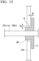
- a gap G 1 between the collar C and the enclosure 170 can be set to, for example, 5 mm or less, 3 mm or less, or 1 mm or less, and as the gap G 1 is narrower, it is more preferable for preventing fiber dust from leaking out of the enclosure 170.
- a cylindrical ring R integrated with the collar C may be inserted into the opening OP provided in the enclosure 170.
- a gap G 2 between the cylindrical ring R and the opening OP can be set to, for example, 5 mm or less, 3 mm or less, or 1 mm or less, and as the gap G 2 is narrower, it is more preferable for preventing fiber dust from leaking out of the enclosure 170.
- the number of dispersing rolls used in the dispersing part is not limited to two. In an example, the number of dispersing rolls used in the dispersing part may be 1 or may be 3 or more.
- a dispersing roll of a type other than the pin roll can be used in the dispersing part.
- the dispersing roll needs an element, such as a pin in a pin roll, that moves in a circumferential direction and hits the short carbon fiber bundles 20 when the dispersing roll is rotated.
- the dispersing roll may have n-fold rotational symmetry (provided that n is an integer of 1 or more, is finite, and is preferably 72 or less) about the rotation axis thereof. n may be 45 or less, 36 or less, or 24 or less.
- the first pin roll 161 shown in FIG. 4 has 4-fold rotational symmetry about the rotation axis.
- a cage roll 164 shown in FIG. 6 is an example of a dispersing roll of a type other than the pin roll.
- the cage roll 164 has a structure in which a plurality of rods 164b are spanned between a pair of disks 164a sharing a rotation axis, and a shaft 164c penetrates through the center of each disk 164a.
- the cage roll 164 since six rods 164b are arranged at equal intervals in the circumferential direction on a cylindrical surface centered about the rotation axis, the cage roll 164 has 6-fold rotational symmetry about the rotation axis thereof.
- the material of the rods 164c is preferably, but not limited to, a metal. When the cage roll 164 is rotated, the rods 164c move in the circumferential direction and hit the short carbon fiber bundles 20.
- the rod 164c of the cage roll 164 may be replaced with a bar having a non-circular cross-section, such as a square bar or a flat bar, or may be replaced with a taut wire.
- a plurality of rods may be disposed at equal intervals in the circumferential direction on each of several concentric cylindrical surfaces centered about the rotation axis.
- the number of rods disposed on each cylindrical surface is not particularly limited, but may be, for example, 3 to 8.
- the cage roll according to an example may have a structure in which a plurality of structural units each comprising a plurality of rods spanned between a pair of disks sharing the rotation axis are lined up in the length direction of the shaft.
- one disk may be shared between the structural units that are adjacent to each other.
- the enclosure 170 comprises an upper part 171 constituting a shooter for guiding the short carbon fiber bundles 20 from the chopping part 150 to the dispersing part 160, and a lower part 172 constituting a housing of a fiber sprinkling booth including the dispersing part 160 on the inside.
- the enclosure 170 is formed using plates made of a metal or a resin and is not breathable.
- the enclosure 170 is usually created using a plurality of plates. It is not necessary for all parts of the enclosure 170 to be formed of plates of the same material.
- the enclosure 170 is preferably formed with metal plates 170 and further grounded as shown in the example of FIG. 17 .
- a grounding cable extends from the lower part 172 of the enclosure 170 to a grounding point 174; however, in an example, the grounding cable may extend from the upper part 171 of the enclosure 170.
- the mode of grounding is not limited to these examples.
- Preferred examples of the material of the metal plates include an aluminum alloy and stainless steel, and the aluminum alloy is more preferable in view of high electrical conductivity.
- the upper part 171 and the lower part 172 of the enclosure are connected without a gap, and at the connection between these no air flows from the inside to the outside of the enclosure 170.
- the configuration of the enclosure 170 is not limited to that shown in FIG. 2 and FIG. 3 .
- the enclosure 170 may have the same horizontal cross-sectional shape from the upper end to the lower end.
- the SMC manufacturing apparatus 100 may have a frame for fixing the chopper, the dispersing roll, and the like, and the frame may form a part of the enclosure 170.
- the enclosure 170 is continuous between a first height H 1 (defined below) and a second height H 2 (defined below).
- the first height H 1 is the height of the rotation axis of each of the cutter roll and the receiving roll of the chopper used in the chopping part 150, and when the heights of these rotation axes are different, the first height H 1 refers to the height of the one located at a higher position.
- the second height H 2 refers to the height of the rotation axis of the dispersing roll having the rotation axis at the lowest position among the dispersing rolls used in the dispersing part 160.
- the position of the upper end of the enclosure 170 may be higher than the first height H 1 .
- the position of the lower end of the enclosure 170 may be lower than the second height Hz, and may be even lower than a third height H 3 that is defined below.
- the third height H 3 refers to a lowest point height of the dispersing roll of which lowest point height is the lowest among the dispersing rolls used in the dispersing part.
- the lowest point height refers to the height obtained by subtracting the maximum radius of the dispersing roll from the height of the rotation axis of the dispersing roll.
- the maximum radius of a dispersing roll is defined as the radius of a cylinder that has the rotation axis of the dispersing roll as the central axis and circumscribes the dispersing roll. Therefore, in the case of a pin roll, the distance from the rotation axis to the tip of the longest pin is the maximum radius, and in the case of a cage roll, the radius of a pair of disks provided for spanning rods or wires is the maximum radius.
- the first height Hi, the second height H 2 , and the third height H 3 are expressed with respect to the surface of the first carrier film 41 as a reference for convenience only, the reference of height does not necessarily have to be the surface of the first carrier film 41.
- a suction nozzle 180 having a suction opening-forming part 180a is mounted at each of the front part and the rear part at the upper end of the enclosure 170. The same applies to the example shown in FIG. 7 .
- Each of the two suction nozzles 180 has the suction opening-forming parts 180a with a longitudinal direction and is arranged such that the longitudinal direction is parallel to the T direction.
- the direction of the suction opening-forming part 180a is set such that the fiber dust rising inside the enclosure 170 can be suctioned.
- the main body of the suction nozzle 180 is a cylinder with both ends closed, and the suction opening-forming part 180a is provided on a side face thereof.
- FIG. 8 is only an example, and there is no limitation in the position and the number of the connection part to the hose in the suction nozzle 180.
- the suction opening formed in the suction opening-forming part 180a is preferably a slit type as shown in the example shown in FIG. 8 but is not limited thereto.
- a plurality of suction openings may be lined up in the suction opening-forming part 180a.
- the shape of the main body of the suction nozzle 180 is not limited and may be a shape other than a cylinder, as is the case of the example shown in FIG. 10 .
- the suction nozzle 180 is connected to a dust collector 182 by the hose 181.
- the dust collector 182 is a dust collector comprising a separator that separates dust from air utilizing centrifugal force, that is, a cyclone dust collector.
- the dust collector 182 is operated during the manufacture of a CF-SMC, and at least a portion of the fiber dust that has risen while floating inside the enclosure 170 to reach the height of the upper end thereof is removed by suction through the suction nozzle 180 before going out of the fiber mat deposition apparatus 130.
- the width W of the suction opening-forming part 180a of the suction nozzle 180 is preferably 50% or more, more preferably 75% or more, and even more preferably 90% or more, and may be even 100% or more of the inner dimension in the T direction of the enclosure 170.
- the suction nozzle 180 may be disposed on the inside of the enclosure 170, in addition to or in place of the upper end of the enclosure 170.
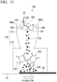
- An example of preferable disposition of the suction nozzles 180 is a disposition in which the suction opening-forming parts 180a face the cutter roll 151 or the receiving roll 152 in the chopping part 150, as is the case of the example of FIG. 11 .
- At least one suction nozzle 180 may be disposed on the inside of the lower part 172 of the enclosure 170.
- the enclosure 170 may be provided with an air outlet, which is connected to the dust collector with a hose.
- the path of the air current generated inside the enclosure 170 during the manufacture of a CF-SMC may change depending on the design and the operating conditions of the fiber mat deposition apparatus 130.
- a suction nozzle is disposed on a path of an air current toward the place.
- how the amount of lint generated changes at several places according to the placement of suction nozzles may also be examined in the case of manufacturing a CF-SMC while operating a dust collector. As described above, it is possible to optimize the placement of the suction nozzles by trial and error.
- the upper end of the enclosure 170 may be closed with a ceiling board 173.
- an air outlet 183 is provided in the enclosure 170, and the air outlet 183 is connected to the dust collector 182 by the hose 181. Placement of the air outlet 183 can be optimized by trial and error, as is the case of the suction nozzle.
- a suction nozzle connected to a dust collector may be disposed on the inside of the enclosure 170.
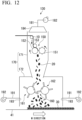
- a suction hood 184 can be disposed above the chopping part 150 as shown in FIG. 12 .
- the suction hood 184 is connected to the dust collector 182 by, for example, the hose 181.
- the enclosure 170 is provided with the air inlet 193 connected to the blower 192 by the hose 191 for the purpose of promoting the removal of fiber dust.
- a suction nozzle connected to a dust collector may be disposed on the inside of the enclosure 170, or an air outlet connected to a dust collector may be provided in the enclosure 170.
- a rod group 200 comprising a plurality of rods arranged in parallel at an interval slightly larger than the fiber length of the short carbon fiber bundles 20 is installed below the dispersing part 160.
- Each rod extends perpendicularly to the T direction and in a horizontal direction or in a direction inclined from the horizontal preferably by 40° or less.
- the purpose of the rod group 200 is to suppress the orientation of the short carbon fiber bundles 20 in the carbon fiber mat 30 deposited on the first carrier film 41 from being biased in the M direction.
- an air supply nozzle 195 connected to an air compressor 194 is installed on the inside of the enclosure 170.
- the discharge opening (air inlet) of the air supply nozzle 195 is directed toward the upper part of the rod group 200.
- Such an air supply nozzle can be installed for preventing fiber dust from deposition not only on the rod group but also on various places inside the enclosure 170. For example, after finding a place where fiber dust is deposited in the case of manufacturing a CF-SMC without an air supply nozzle provided inside the enclosure 170, the air supply nozzle can be disposed with the discharge opening thereof directing toward that place.
- the upper part 171 of the enclosure 170 when the amount of fiber dust drifting toward the chopping part 150 is reduced by, for example, disposing a suction nozzle on the inside of the lower part 172 of the enclosure, the upper part 171 of the enclosure 170 may be omitted.
- the upper part 171 of the enclosure 170 only a part whose diameter decreases downward, including the connection with the lower part 172, may be left while the rest may be omitted.
- the impregnator 140 is of a type that has been conventionally used in SMC manufacturing apparatuses and comprises two belt conveyors for conveying a stack 60 by sandwiching it from above and below between two conveyor belts, and rolls for pressurizing the stack 60 by putting it therebetween together with the two conveyor belts.
- the stack 60 is formed by bonding together a first carrier film 41 and a second carrier film 42, with the first resin paste layer 51L, the carbon fiber mat 30, and the second resin paste layer 52L sandwiched therebetween, using a laminator 70 provided between the fiber mat deposition apparatus 130 and the impregnator 140.
- a continuous carbon fiber bundle 10 is drawn out from a fiber package prepared in advance.
- the continuous carbon fiber bundle 10 may be drawn out from a bobbin package on a creel by unwinding from outside or may be drawn out from a package from which a bobbin has been pulled out by unwinding from inside.
- a filament number of the continuous carbon fiber bundle 10, that is, the number of carbon fiber filaments constituting the continuous carbon fiber bundle 10, is preferably in the range of 3K to 100K. Since K means 1000, 3K is 3000, and 100K is 100000.
- the filament number of the continuous carbon fiber bundle 10 may be, for example, 12K, 15K, 20K, 24K, 48K, 50K, or 60K.
- the continuous carbon fiber bundle 10 may be partially split into a plurality of sub-bundles in advance.
- a plurality of the continuous carbon fiber bundles 10 are aligned to be parallel to each other and are supplied to the fiber mat deposition apparatus 130 from a direction orthogonal to the T direction.
- the continuous carbon fiber bundle 10 is cut to a predetermined length into short carbon fiber bundles 20.
- the predetermined length is typically in the range of 10 to 60 mm and may be 0.5 inches (about 1.3 cm), 1 inch (about 2.5 cm), 2 inches (about 5.1 cm), or the like, without being limited thereto.
- the short carbon fiber bundles 20 fall toward the dispersing part 160 below the chopping part 150 and are dispersed by the first pin roll 161 and the second pin roll 162 and deposited on a first carrier film traveling below the fiber mat deposition apparatus 130 to form carbon fiber mat 30.
- the treatment performed in the dispersing part 160 is not intended to defibrate the short carbon fiber bundles 20.
- the circumferential speed at the pin tips of the first pin roll 161 and the second pin roll 162 is set such that a fiber bundle having a filament number of less than 0.5K is not generated as far as possible, or even if generated, the contained amount thereof in the carbon fiber mat 30 is less than 1% by weight.
- the circumferential speed at the pin tips of the first pin roll 161 and the second pin roll 162 may be set such that a fiber bundle having a filament number of less than 0.2K are not generated as far as possible, or even if generated, the contained amount thereof in the carbon fiber mat 30 is less than 1% by weight.
- Rotating both the first pin roll 161 and the second pin roll 162 is advantageous in preventing the short carbon fiber bundles 20 from being jammed between these two pin rolls.
- the first pin roll 161 rotates such that the pins 161b move downward from above on the side facing the second pin roll 162, and the second pin roll 162 rotates such that the pins 162b move downward from above on the side facing the first pin roll 161.
- the carbon fiber mat 30 is less likely to have front and back.
- both heavy carbon fiber bundles and light carbon fiber bundles pass through a narrow space between the two pin rolls and fall on the first carrier film 41 simultaneously. In other words, it is because the position where heavy short carbon fiber bundles fall and the position where light short carbon fiber bundles fall are less likely to tend to be shifted along the conveyance direction of the first carrier film.
- Another reason for rotating each the first pin roll 161 and the second pin roll 162 such that the pins move downward from above on the side farcing the other pin roll is to avoid applying a strong shear force to the short carbon fiber bundles 20 passing through between these two pin rolls.
- a strong shear force causes fluffing or deterioration of straightness of the carbon fiber bundle.
- the circumferential speeds at the pin tips are equal between the first pin roll 161 and the second pin roll 162.
- the first resin paste 51 is applied on one surface of the first carrier film 41 drawn out from a roll using the first applicator 110.
- the first resin paste 51 is a thermosetting resin composition, whose base resin is, for example, a vinyl ester resin (also called epoxy acrylate resin), an unsaturated polyester resin, an epoxy resin, a polyimide resin, a maleimide resin, or a phenol resin, without being limited thereto.
- a mixed resin of a vinyl ester resin and an unsaturated polyester resin may be used as the base resin.
- a curing agent, a polymerization inhibitor, a thickener, a reactive diluent, a low shrinkage agent, a flame retardant, an antibacterial agent, and the like are blended in the first resin paste 51, as necessary.
- the second resin paste 52 having the same formulation as the first resin paste 51 is applied on one surface of the second carrier film 42 using the second applicator 120.
- the second carrier film 42 is superposed on the first carrier film 41 carrying the carbon fiber mat 30 on the upper surface, in such a manner that the surface of the second carrier film 42 on which the second resin paste layer 52L is formed faces downward.
- the carbon fiber mat 30 is impregnated with the first resin paste 51 and the second resin paste 52 to be a resin-impregnated carbon fiber mat.
- the resin-impregnated carbon fiber mat is wound on a bobbin while still being sandwiched between the first carrier film 41 and the second carrier film 42.
- the resin-impregnated carbon fiber mat wound on the bobbin is thickened as necessary before being shipped as a CF-SMC.
- the dust collector 182 is continuously operated throughout the manufacture of the CF-SMC.
- Preferable embodiments of the present invention include the following but are not limited thereto.
- a method of manufacturing a sheet molding compound comprising: (i) drawing out a carrier film from a roll to travel on a conveyance path such that the surface of the carrier film is horizontal; (ii) cutting a continuous carbon fiber bundle into short carbon fiber bundles with a chopper disposed above the conveyance path; (iii) allowing the short carbon fiber bundles to fall onto the carrier film traveling on the conveyance path while dispersing them using a dispersing roll disposed below the chopper to deposit a carbon fiber mat on the carrier film; (iv) impregnating the carbon fiber mat with a thermosetting resin composition to obtain a resin-impregnated carbon fiber mat; and v) concurrently with the deposition of the carbon fiber mat, removing fiber dust generated from the short carbon fiber bundles due to contact with the dispersing roll using a dust collector.
- Embodiment 2 The method of manufacturing according to Embodiment 1, wherein a first pin roll and a second pin roll, which are arranged side by side and have rotation axes parallel to each other, are used as the dispersing roll.
- Embodiment 3 The method of manufacturing according to Embodiment 2, wherein the first pin roll is rotationally driven such that pins move downward from above on a side facing the second pin roll, and the second pin roll is rotationally driven such that pins move downward from above on a side facing the first pin roll.
- Embodiment 4 The method of manufacturing according to Embodiment 2 or 3, wherein a sum of a maximum radius of the first pin roll and a maximum radius of the second pin roll is larger than a distance between the rotation axes of the first pin roll and the second pin roll.
- Embodiment 6 The method of manufacturing according to any one of Embodiments 2 to 5, wherein a circumferential speed at a pin tip of the first pin roll is equal to a circumferential speed at a pin tip of the second pin roll.
- Embodiment 7 The method of manufacturing according to any one of Embodiments 1 to 6, wherein the contained amount of a carbon fiber bundle having a filament number of 0. 5K or more in the carbon fiber mat is 99% by weight or more.
- Embodiment 8 The method of manufacturing according to any one of Embodiments 1 to 7, wherein before the deposition of the carbon fiber mat on the carrier film, a resin paste comprising the thermosetting resin composition is applied on one surface of the carrier film, and after the deposition of the carbon fiber mat, another carrier film with another resin paste comprising the thermosetting resin composition applied on one surface is superposed on the carrier film to form a stack, further followed by pressurizing the stack for the impregnation.
- Embodiment 9 The method of manufacturing according to any one of Embodiments 1 to 8, wherein the removal includes removing the fiber dust while it is floating.
- a method of manufacturing a sheet molding compound using a fiber mat deposition apparatus comprising a chopping part and a dispersing part disposed below the chopping part, the method comprising: (i) drawing out a carrier film from a roll to travel on a conveyance path such that the surface of the carrier film is horizontal; (ii) cutting a continuous carbon fiber bundle into short carbon fiber bundles in the chopping part of the fiber mat deposition apparatus disposed above the conveyance path; (iii) allowing the short carbon fiber bundles to fall onto the carrier film traveling on the conveyance path while dispersing them in the dispersing part of the fiber mat deposition apparatus using a dispersing roll having a rotation axis parallel to a T direction to deposit a carbon fiber mat on the carrier film; (iv) impregnating the carbon fiber mat with a thermosetting resin composition to obtain a resin-impregnated carbon fiber mat; and (v) concurrently with the deposition of the carbon fiber mat, removing fiber dust generated from the
- Embodiment 11 The method of manufacturing according to Embodiment 10, wherein the dispersing roll is a pin roll or a cage roll.
- Embodiment 12 The method of manufacturing according to Embodiment 10 or 11, wherein the dispersing roll has n-fold rotational symmetry (provided that n is an integer of 1 or more, is finite, and is preferably 72 or less) about the rotation axis thereof.
- Embodiment 13 The method of manufacturing according to any one of Embodiments 10 to 12, wherein the dispersing part of the fiber mat deposition apparatus is disposed on the inside of an enclosure.
- Embodiment 14 The method of manufacturing according to Embodiment 13, wherein at least one end of a shaft of the dispersing roll protrudes to the outside of the enclosure through an opening provided in the enclosure.
- Embodiment 15 The method of manufacturing according to Embodiment 13, wherein each of both ends of a shaft of the dispersing roll protrudes out of the enclosure through an opening provided in the enclosure, and a pair of bearings supporting the shaft are both disposed on the outside of the enclosure.
- Embodiment 16 The method of manufacturing according to Embodiment 14 or 15, wherein the dispersing roll is provided with a collar which is adjacent to the opening on the inside of the enclosure, and on a plane perpendicular to the T direction an orthographic projection of the opening falls inside an outline of an orthographic projection of the collar.
- Embodiment 17 The method of manufacturing according to Embodiment 16, wherein a gap between the collar and the enclosure is 5 mm or less.
- Embodiment 18 The method of manufacturing according to any one of Embodiments 14 to 17, wherein an electric motor and a power transmission system for driving the dispersing roll are arranged on the outside of the enclosure.
- Embodiment 19 The method of manufacturing according to any one of Embodiments 13 to 18, wherein the enclosure is provided such that the chopping part is disposed on the inside of the enclosure.
- Embodiment 20 The method of manufacturing according to any one of Embodiments 13 to 19, wherein a suction nozzle connected to at least any of the one or more dust collectors is disposed at an upper end of the enclosure.
- Embodiment 21 The method of manufacturing according to Embodiment 19, wherein an upper end of the enclosure is closed with a ceiling board.
- Embodiment 22 The method of manufacturing according to Embodiment 19, wherein a suction hood connected to at least any of the one or more dust collectors is disposed above the chopping part.
- Embodiment 23 The method of manufacturing according to Embodiment 22, wherein there is no gap between the suction hood and the enclosure.
- Embodiment 24 The method of manufacturing according to any one of Embodiments 13 to 23, wherein a suction nozzle connected to at least any of the one or more dust collectors is disposed on the inside of the enclosure.
- Embodiment 25 The method of manufacturing according to any one of Embodiments 13 to 24, wherein the enclosure is provided with an air outlet, which is connected to at least any of the one or more dust collectors.
- Embodiment 26 The method of manufacturing according to any one of Embodiments 13 to 25, further comprising supplying air to the inside of the enclosure concurrently with the deposition of the carbon fiber mat.
- Embodiment 27 The method of manufacturing according to Embodiment 26, wherein either one or both of a blower and an air compressor are used to supply the air.
- Embodiment 28 The method of manufacturing according to Embodiment 26, wherein an air inlet connected to a blower or an air compressor is disposed on the inside of the enclosure.
- Embodiment 29 The method of manufacturing according to Embodiment 26 or 28, wherein the enclosure is provided with an air inlet connected to a blower or an air compressor.
- Embodiment 30 The method of manufacturing according to any one of Embodiments 13 to 29, wherein the enclosure is formed of metal plates and is grounded.
- Embodiment 31 The method of manufacturing according to any one of Embodiments 10 to 30, wherein before the deposition of the carbon fiber mat on the carrier film, a resin paste comprising the thermosetting resin composition is applied on one surface of the carrier film, and after the deposition of the carbon fiber mat, another carrier film with another resin paste comprising the thermosetting resin composition applied on one surface is superposed on the carrier film to form a stack, further followed by pressurizing the stack for the impregnation.
- Embodiment 32 The method of manufacturing according to any one of Embodiments 10 to 31, wherein the contained amount of a carbon fiber bundle having a filament number of 0. 5K or more in the carbon fiber mat is 99% by weight or more.
- Embodiment 33 The method of manufacturing according to any one of Embodiments 10 to 32, wherein the removal includes removing the fiber dust while it is floating.
- a fiber mat deposition apparatus disposed above a conveyance path and used for depositing a carbon fiber mat on a carrier film that travels on the conveyance path with its surface horizontal, the fiber mat deposition apparatus comprising: a chopping part for cutting a continuous carbon fiber bundle into short carbon fiber bundles; and a dispersing part disposed below the chopping part for allowing the short carbon fiber bundles to fall onto the carrier film while dispersing them using a dispersing roll having a rotation axis parallel to a T direction, wherein the dispersing part is disposed on the inside of an enclosure, and at least one end of a shaft of the dispersing roll protrudes to the outside of the enclosure through an opening provided in the enclosure.
- a fiber mat deposition apparatus disposed above a conveyance path and used for depositing a carbon fiber mat on a carrier film that travels on the conveyance path with its surface horizontal, the fiber mat deposition apparatus comprising: a chopping part for cutting a continuous carbon fiber bundle into short carbon fiber bundles; and a dispersing part disposed below the chopping part for allowing the short carbon fiber bundles to fall onto the carrier film while dispersing them using a dispersing roll having a rotation axis parallel to a T direction, wherein the dispersing part is disposed on the inside of an enclosure, each of both ends of a shaft of the dispersing roll protrudes out of the enclosure through an opening provided in the enclosure, and a pair of bearings supporting the shaft are both disposed on the outside of the enclosure.
- Embodiment 36 The fiber mat deposition apparatus according to Embodiment 34 or 35, wherein the dispersing roll is provided with a collar which is adjacent to the opening on the inside of the enclosure, and on a plane perpendicular to the T direction an orthographic projection of the opening falls inside an outline of an orthographic projection of the collar.
- Embodiment 38 The fiber mat deposition apparatus according to any one of Embodiments 34 to 37, wherein an electric motor and a power transmission system for driving the dispersing roll are arranged on the outside of the enclosure.
- a fiber mat deposition apparatus comprising: a chopping part for cutting a continuous carbon fiber bundle into short carbon fiber bundles; and a dispersing part disposed below the chopping part and configured for allowing the short carbon fiber bundles to fall onto a carrier film while dispersing them using a dispersing roll, wherein the dispersing part is disposed on the inside of an enclosure, and the enclosure is formed of metal plates and is grounded.
- Embodiment 41 The fiber mat deposition apparatus according to any one of Embodiments 34 to 40, wherein the enclosure is provided such that the chopping part is disposed on the inside of the enclosure.
- Embodiment 42 The fiber mat deposition apparatus according to any one of Embodiments 34 to 41, wherein a suction nozzle connected to a dust collector is disposed at an upper end of the enclosure.
- Embodiment 43 The fiber mat deposition apparatus according to Embodiment 41, wherein an upper end of the enclosure is closed with a ceiling board.
- Embodiment 44 The fiber mat deposition apparatus according to Embodiment 41, wherein a suction hood connected to a dust collector is disposed above the chopping part.
- Embodiment 45 The fiber mat deposition apparatus according to Embodiment 44, wherein there is no gap between the suction hood and the enclosure.
- Embodiment 46 The fiber mat deposition apparatus according to any one of Embodiments 34 to 45, wherein a suction nozzle connected to a dust collector is disposed on the inside of the enclosure.
- Embodiment 47 The fiber mat deposition apparatus according to any one of Embodiments 34 to 46, wherein the enclosure is provided with an air outlet, which is connected to a dust collector.
- Embodiment 48 The fiber mat deposition apparatus according to any one of Embodiments 34 to 47, further comprising an air inlet which is disposed on the inside of the enclosure and is connected to a blower or an air compressor.
- Embodiment 49 The fiber mat deposition apparatus according to any one of Embodiments 34 to 48, further comprising an air inlet which is provided in the enclosure and is connected to a blower or an air compressor.
- Embodiment 50 The fiber mat deposition apparatus according to any one of Embodiments 34 to 49, wherein the dispersing roll is a pin roll or a cage roll.
- Embodiment 51 The fiber mat deposition apparatus according to any one of Embodiments 34 to 50, wherein the dispersing roll has n-fold rotational symmetry (provided that n is an integer of 1 or more, is finite, and is preferably 72 or less) about the rotation axis thereof.
- Embodiment 52 A method of manufacturing a carbon fiber mat, the method comprising using the fiber mat deposition apparatus according to any one of Embodiments 34 to 51.
- Embodiment 53 A method of manufacturing a sheet molding compound, the method comprising: depositing a carbon fiber mat by using the fiber mat deposition apparatus according to any one of Embodiments 34 to 51, and impregnating the carbon fiber mat with a thermosetting resin composition.
- Embodiment 54 Use of the fiber mat deposition apparatus according to any one of Embodiments 34 to 51 for manufacturing of a sheet molding compound.
- Embodiment 55 Use of the fiber mat deposition apparatus according to any one of Embodiments 34 to 51 in a sheet molding compound manufacturing apparatus.
- Embodiment 56 The use according to Embodiment 55, wherein the sheet molding compound manufacturing apparatus comprises two applicators, a laminator, and an impregnator.
- a sheet molding compound manufacturing apparatus comprising the fiber mat deposition apparatus according to any one of Embodiments 34 to 51.
- Embodiment 58 The sheet molding compound manufacturing apparatus according to Embodiment 57, further comprising two applicators, a laminator, and an impregnator.
- a sheet molding compound manufacturing apparatus comprising a fiber mat deposition apparatus, two applicators, a laminator, an impregnator, and one or more dust collectors, which may include a cyclone dust collector.
- Embodiment 60 The sheet molding compound manufacturing apparatus according to Embodiment 59, wherein the fiber mat deposition apparatus has a chopping part for cutting a continuous carbon fiber bundle into short carbon fiber bundles, and a dispersing part disposed below the chopping part for allowing the short carbon fiber bundles to fall onto a carrier film while dispersing them using a dispersing roll.
- Embodiment 61 The sheet molding compound manufacturing apparatus according to Embodiment 60, wherein the dispersing roll is a pin roll or a cage roll.
- Embodiment 62 The sheet molding compound manufacturing apparatus according to Embodiment 60 or 61, wherein the dispersing roll has n-fold rotational symmetry (provided that n is an integer of 1 or more, is finite, and is preferably 72 or less) about the rotation axis thereof.
- Embodiment 63 The sheet molding compound manufacturing apparatus according to any one of Embodiments 60 to 62, wherein in the fiber mat deposition apparatus, the dispersing part is disposed on the inside of an enclosure.
- Embodiment 64 The sheet molding compound manufacturing apparatus according to Embodiment 63, wherein the enclosure is provided such that the chopping part is disposed on the inside of the enclosure.
- Embodiment 65 The sheet molding compound manufacturing apparatus according to Embodiment 63 or 64, wherein a suction nozzle connected to at least any of the one or more dust collectors is disposed at an upper end of the enclosure.
- Embodiment 66 The sheet molding compound manufacturing apparatus according to Embodiment 64, wherein an upper end of the enclosure is closed with a ceiling board.
- Embodiment 67 The sheet molding compound manufacturing apparatus according to Embodiment 65, wherein a suction hood connected to at least any of the one or more dust collectors is disposed above the chopping part.
- Embodiment 68 The sheet molding compound manufacturing apparatus according to Embodiment 67, wherein there is no gap between the suction hood and the enclosure.
- Embodiment 69 The sheet molding compound manufacturing apparatus according to any one of Embodiments 63 to 68, wherein a suction nozzle connected to at least any of the one or more dust collectors is disposed on the inside of the enclosure.
- Embodiment 70 The sheet molding compound manufacturing apparatus according to any one of Embodiments 63 to 69, wherein the enclosure is provided with an air outlet, which is connected to at least any of the one or more dust collectors.
- Embodiment 71 The sheet molding compound manufacturing apparatus according to any one of Embodiments 63 to 70, further comprising an air inlet which is disposed on the inside of the enclosure and is connected to a blower or an air compressor.
- Embodiment 72 The sheet molding compound manufacturing apparatus according to any one of Embodiments 63 to 71, further comprising an air inlet which is provided in the enclosure and is connected to a blower or an air compressor.
- Embodiment 73 The sheet molding compound manufacturing apparatus according to any one of Embodiments 63 to 72, wherein the enclosure is formed of metal plates and is grounded.
- Embodiment 74 A method of manufacturing a CF-SMC, comprising using the sheet molding compound manufacturing apparatus according to any one of Embodiments 57 to 73.
- a CF-SMC manufactured using the method or apparatus according to the embodiments is used for molding CFRP products using, for example, a compression molding method.
- CFRP products that can be manufactured using the CF-SMC have a wide range of applications, including manned aircraft, unmanned aircraft, automobiles, ships, railway vehicles, and various other transportation equipment, sporting goods, and leisure goods.
Landscapes
- Engineering & Computer Science (AREA)
- Textile Engineering (AREA)
- Mechanical Engineering (AREA)
- Chemical & Material Sciences (AREA)
- Chemical Kinetics & Catalysis (AREA)
- Dispersion Chemistry (AREA)
- General Chemical & Material Sciences (AREA)
- Composite Materials (AREA)
- Inorganic Chemistry (AREA)
- Reinforced Plastic Materials (AREA)
Abstract
Description
- The present invention mainly relates to a method of manufacturing a sheet molding compound (SMC), particularly a method of manufacturing an SMC using carbon fibers (CF) as a reinforcement (CF-SMC), and a fiber mat deposition apparatus used for the manufacture of a CF-SMC.
- Priority is claimed on
Japanese Patent Application No. 2021-116973, filed July 15, 2021 Japanese Patent Application No. 2022-078871, filed May 12, 2022 - Carbon fiber reinforced plastics (CFRP) are lightweight composite materials with excellent mechanical characteristics, which are suitable for parts of manned aircraft, unmanned aircraft, automobiles, ships, railway vehicles, and other transportation equipment, and the importance of the materials has increased steadily in recent years.
- A material preferably used when manufacturing CFRP products by compression molding is a carbon fiber prepreg, which is an intermediate material. A carbon fiber prepreg is obtained by impregnating a reinforcement comprising carbon fibers with an uncured thermosetting resin composition.
- A CF-SMC is a kind of carbon fiber prepreg, and in a manufacturing process thereof, a continuous carbon fiber bundle is cut with a chopper into short carbon fiber bundles, which are allowed to fall onto a traveling carrier film to form a carbon fiber mat. A CF-SMC is made by impregnating the carbon fiber mat with a thermosetting resin composition.
- There has been proposed a fiber mat manufacturing apparatus in which a pin roll or a cage roll is disposed between a chopper and a conveyance path of a carrier film for the purpose of letting the short fiber bundles falling from the chopper onto the carrier film disperse uniformly or split by hitting into smaller bundles (Patent Document 1 and Patent Document 2).
-
- [Patent Document 1]
PCT International Publication No. WO 2019/142851 - [Patent Document 2]
PCT International Publication No. WO 2021/010084 - When short carbon fiber bundles are brought into contact with a dispersing roll such as a pin roll or a cage roll, fiber dust is generated due to the impact. Fiber dust may float due to the influence of an air flow generated by rotation of the dispersing roll and then may adhere to, for example, the surface of a member of an SMC manufacturing apparatus to form lint. When largely grown lint falls and mixes into the carbon fiber mat, poor impregnation occurs in that portion. Since the CF-SMC does not sufficiently flow in a poorly impregnated part, there is a risk that a CF-SMC with a poorly impregnated part may damage a mold when used for compression molding.
- The fiber dust also has a risk of contaminating mechanical elements included in the SMC manufacturing apparatus or deteriorating the work environment in a room in which the SMC manufacturing apparatus is installed. Since fiber dust generated from carbon fibers has electrical conductivity, the fiber dust may impair the operation of electrical and electronic equipment.
- Objects of the present invention include providing a manufacturing technology for CF-SMC capable of suppressing lint originating from the fiber dust from incorporation into a product despite using a dispersing roll.
- Objects of the present invention further include providing a fiber mat deposition apparatus capable of suppressing an adverse effect of the fiber dust on a mechanical element included in an SMC manufacturing apparatus or a work environment in a room in which an SMC manufacturing apparatus is installed.
- In the present specification, problems that can be solved by each embodiment of the present invention may be explicitly or implicitly disclosed.
- According to an aspect of the present invention, there is provided a method of manufacturing a sheet molding compound, the method comprising: (i) drawing out a carrier film from a roll to travel on a conveyance path such that the surface of the carrier film is horizontal; (ii) cutting a continuous carbon fiber bundle into short carbon fiber bundles with a chopper disposed above the conveyance path; (iii) allowing the short carbon fiber bundles to fall onto the carrier film traveling on the conveyance path while dispersing them using a dispersing roll disposed below the chopper to deposit a carbon fiber mat on the carrier film; (iv) impregnating the carbon fiber mat with a thermosetting resin composition to obtain a resin-impregnated carbon fiber mat; and (v) concurrently with the deposition of the carbon fiber mat, removing fiber dust generated from the short carbon fiber bundles due to contact with the dispersing roll using a dust collector.
- According to another aspect of the present invention, there is provided a method of manufacturing a sheet molding compound using a fiber mat deposition apparatus comprising a chopping part and a dispersing part disposed below the chopping part, the method comprising: (i) drawing out a carrier film from a roll to travel on a conveyance path such that the surface of the carrier film is horizontal; (ii) cutting a continuous carbon fiber bundle into short carbon fiber bundles in the chopping part of the fiber mat deposition apparatus disposed above the conveyance path; (iii) allowing the short carbon fiber bundles to fall onto the carrier film traveling on the conveyance path while dispersing them in the dispersing part of the fiber mat deposition apparatus using a dispersing roll having a rotation axis parallel to a T direction to deposit a carbon fiber mat on the carrier film; (iv) impregnating the carbon fiber mat with a thermosetting resin composition to obtain a resin-impregnated carbon fiber mat; and (v) concurrently with the deposition of the carbon fiber mat, removing fiber dust generated from the short carbon fiber bundles due to contact with the dispersing roll using one or more dust collectors.
- According to still another aspect of the present invention, there is provided a fiber mat deposition apparatus disposed above a conveyance path and used for depositing a carbon fiber mat on a carrier film that travels on the conveyance path with its surface horizontal, the fiber mat deposition apparatus comprising: a chopping part for cutting a continuous carbon fiber bundle into short carbon fiber bundles; and a dispersing part disposed below the chopping part for allowing the short carbon fiber bundles to fall onto the carrier film while dispersing them using a dispersing roll having a rotation axis parallel to a T direction, wherein the dispersing part is disposed on the inside of an enclosure, and at least one end of a shaft of the dispersing roll protrudes to the outside of the enclosure through an opening provided in the enclosure.
- According to still another aspect of the invention, there is provided a fiber mat deposition apparatus disposed above a conveyance path and used for depositing a carbon fiber mat on a carrier film that travels on the conveyance path with its surface horizontal, the fiber mat deposition apparatus comprising: a chopping part for cutting a continuous carbon fiber bundles into short carbon fiber bundles; and a dispersing part disposed below the chopping part for allowing the short carbon fiber bundles to fall onto the carrier film while dispersing them using a dispersing roll having a rotation axis parallel to a T direction, wherein the dispersing part is disposed on the inside of an enclosure, each of both ends of a shaft of the dispersing roll protrudes out of the enclosure through an opening provided in the enclosure, and a pair of bearings supporting the shaft are both disposed on the outside of the enclosure.
- According to still another aspect of the present invention, there is provided a fiber mat deposition apparatus comprising: a chopping part for cutting a continuous carbon fiber bundle into short carbon fiber bundles; and a dispersing part disposed below the chopping part for allowing the short carbon fiber bundles to fall onto a carrier film while dispersing them using a dispersing roll, wherein the dispersing part is disposed on the inside of an enclosure, and the enclosure is formed of metal plates and is grounded.
- According to still another aspect of the present invention, there is provided a sheet molding compound manufacturing apparatus comprising a fiber mat deposition apparatus, two applicators, a laminator, an impregnator, and one or more dust collectors.
- According to an aspect of the present invention, there is provided a manufacturing technology for CF-SMC capable of suppressing lint originating from fiber dust generated from short carbon fiber bundles due to contact with a dispersing roll from incorporation into a product.
- According to another aspect of the present invention, there is provided a fiber mat deposition apparatus that can suppress an adverse effect of fiber dust generated from short carbon fiber bundles due to contact with a dispersing roll, on a mechanical element included in an SMC manufacturing apparatus or a work environment in a room where an SMC manufacturing apparatus is installed.
-
-
FIG. 1 is a schematic diagram of an SMC manufacturing apparatus. -
FIG. 2 is a schematic diagram of a fiber mat deposition apparatus. -
FIG. 3 is a schematic diagram of a fiber mat deposition apparatus. -
FIG. 4 is a schematic diagram of a pin roll. -
FIG. 5 is a schematic diagram showing a positional relationship between two pin rolls in a disperser. -
FIG. 6 is a schematic diagram of a cage roll. -
FIG. 7 is a schematic diagram of a fiber mat deposition apparatus. -
FIG. 8 is a schematic diagram of a suction nozzle. -
FIG. 9 is a schematic diagram of a suction nozzle. -
FIG. 10 is a schematic diagram of a suction nozzle. -
FIG. 11 is a schematic diagram of a fiber mat deposition apparatus. -
FIG. 12 is a schematic diagram of a fiber mat deposition apparatus. -
FIG. 13 is a schematic diagram of a fiber mat deposition apparatus. -
FIG. 14 is a schematic diagram showing a part of a fiber mat deposition apparatus. -
FIG. 15 is a schematic diagram showing a part of a fiber mat deposition apparatus. -
FIG. 16 is a schematic diagram of a fiber mat deposition apparatus. -
FIG. 17 is a schematic diagram of a fiber mat deposition apparatus. - The term "T direction" as used in the present specification means a direction that is horizontal and is perpendicular to an M direction. The M direction is a traveling direction of the carrier film at the time of manufacturing a CF-SMC. For example, in
FIG. 1 ,FIG. 2 ,FIGS. 11 to 13 ,FIG. 16 , andFIG. 17 , the T direction is perpendicular to the paper surface. - The term "metal" as used in the present specification includes not only a simple metal substance but also an alloy.
- An example of an SMC manufacturing apparatus that can be preferably used in the method of manufacturing a CF-SMC according to the embodiment is shown in
FIG. 1 . - In
FIG. 1 , anSMC manufacturing apparatus 100 has afirst applicator 110, asecond applicator 120, a fibermat deposition apparatus 130, and animpregnator 140. - The
first applicator 110 is used to apply afirst resin paste 51 on afirst carrier film 41 to form a firstresin paste layer 51L. - The
second applicator 120 is used to apply asecond resin paste 52 on asecond carrier film 42 to form a secondresin paste layer 52L. - As shown in
FIG. 2 andFIG. 3 , the fibermat deposition apparatus 130 is disposed above a conveyance path of thefirst carrier film 41 and has achopping part 150, a dispersingpart 160, anenclosure 170, and asuction nozzle 180. - Below the fiber
mat deposition apparatus 130, the surface of thefirst carrier film 41 conveyed is held horizontal. This is to prevent fallen shortcarbon fiber bundles 20 and a depositedfiber mat 30 from moving on the surface of thefirst carrier film 41 due to gravity. - In the
chopping part 150, a chopper of the type that has been conventionally used in SMC manufacturing apparatuses, that is, a chopper comprising acutter roll 151, a receiving roll (rubber roll) 152, and aguide roll 153, each of which has a rotation axis parallel to the T direction, is used. During the manufacture of a CF-SMC, a continuouscarbon fiber bundle 10 supplied to the fibermat deposition apparatus 130 is cut in thechopping part 150. - The chopping
part 150 may be configured to cut the continuouscarbon fiber bundle 10 such that the longitudinal direction of the continuouscarbon fiber bundle 10 and the cut surface form an angle of 80° or less, 45° or less, or 30° or less. - In the fiber
mat deposition apparatus 130, the choppingpart 150 is disposed on the inside of theenclosure 170. - An electric motor and a power transmission system (not shown in the figure) for rotationally driving the
cutter roll 151 and the receivingroll 152 are preferably disposed outside theenclosure 170 in order to avoid contamination by fiber dust. - When the
cutter roll 151 and the receivingroll 152 are connected to the power transmission system on the outside of theenclosure 170, an opening is provided in theenclosure 170 in order for at least one end of a shaft included in each of those rolls to protrude out of theenclosure 170. It is desirable that the size of the opening is set to the minimum necessary, in order to prevent fiber dust from leaking out of theenclosure 170 through the opening. - Preventing fiber dust from leaking out of the
enclosure 170 is beneficial in terms of improving the work environment in the room in which theSMC manufacturing apparatus 100 is installed, in addition to preventing contamination of the mechanical elements disposed outside theenclosure 170. - In the dispersing
part 160, a pair of pin rolls disposed side by side, that is, afirst pin roll 161 and asecond pin roll 162, are used as the dispersing rolls. The dispersingpart 160 is disposed below the choppingpart 150, and during the manufacture of a CF-SMC, the shortcarbon fiber bundles 20 falling from the choppingpart 150 are dispersed by the dispersingpart 160. - Both the
first pin roll 161 and thesecond pin roll 162 have a rotation axis parallel to the T direction, and both are rotationally driven by a drive mechanism (not shown in the figure). - The speeds of rotation of the
first pin roll 161 and thesecond pin roll 162 may be independently controllable. - As shown in
FIG. 4 , thefirst pin roll 161 has acylinder 161a, a plurality ofpins 161b disposed on the circumferential surface of thecylinder 161a, and ashaft 161c that penetrates the center of thecylinder 161a in the direction of the rotation axis. It is preferable that all of the plurality ofpins 161b have the same shape and dimensions as each other. - Both the
cylinder 161a and thepin 161b are rigid bodies and are formed of, for example, a metal. - The diameter of the
cylinder 161a is not limited; however, the diameter may be, for example, 60 mm to 150 mm. As the diameter of thecylinder 161a is larger, the entirety of thepins 161b moves at a higher circumferential speed when thefirst pin roll 161 is rotated, and therefore, the ability to disperse the short carbon fiber bundles increases. - The
pins 161b extend perpendicularly to the rotation axis of thefirst pin roll 161, and although not limited thereto, thepins 161b have, for example, a columnar shape. The boundary between an end surface and the circumferential surface of thepin 161b may be chamfered. - The diameter of the
pin 161b is not limited, but may be, for example, 1 mm to 5 mm. - The length of the
pin 161b, that is, the distance from the tip to the base of the pin is not limited, but may be, for example, 10 mm to 50 mm. - It is preferable that the disposition of the
pins 161b on the circumferential surface of thecylinder 161a is periodic in each of the axial direction and the circumferential direction. - The period of disposition of the
pins 161b on the circumferential surface of thecylinder 161a may be, for example, 5 mm or more and less than 20 mm, 20 mm or more and less than 40 mm, or 40 mm or more and less than 60 mm, in the axial direction. - In the example of
FIG. 4 , the disposition of thepins 161b on the circumferential surface of thecylinder 161a has a period of 90° in the circumferential direction; however, a period other than 90° including, for example, 5°, 10°, 15°, 20°, 24°, 30°, 45°, 60°, 72°, 120°, or 180° can also be employed. - In the present specification, the maximum radius of the pin roll is defined as a distance from the rotation axis of the pin roll to the tip of the longest pin. In the
first pin roll 161, the radius of thecylinder 161a is preferably half or more and more preferably 75% or more of the maximum radius of thefirst pin roll 161. This is because as the ratio of the cylinder radius to the maximum radius of the pin roll is higher, the difference between the circumferential speed at the tip of the pin and the circumferential speed at the base of the pin is smaller when the pin roll is rotating. - All of the above description with regard to the
first pin roll 161 also applies to thesecond pin roll 162. - Without imposing any limitation, in order to reduce the cost of designing, manufacturing, and maintaining the fiber
mat deposition apparatus 130, it is preferable to match the design and specifications of thefirst pin roll 161 and thesecond pin roll 162 in as many items as possible, including the axial direction length, the maximum radius, the cylinder diameter, the shape, dimensions, number, and disposition of the pins, and the materials of the cylinder and the pins. - In order for more short
carbon fiber bundles 20 to be hit by the pins of thefirst pin roll 161 and thesecond pin roll 162 when passing between these pin rolls, it is preferable that the sum of the maximum radius rM1 of thefirst pin roll 161 and the maximum radius rM2 of thesecond pin roll 162 is larger than the distance d12 between the rotation axes of these two pin rolls, as shown inFIG. 5 . - The sum of the maximum radius rM1 of the
first pin roll 161 and the cylinder radius rC2 of thesecond pin roll 162 and the sum of the cylinder radius rC1 of thefirst pin roll 161 and the maximum radius rM2 of thesecond pin roll 162 are both smaller than the distance d12 between the rotation axes of the two pin rolls. - In an example, the sum of the maximum radius rM1 of the
first pin roll 161 and the maximum radius rM2 of thesecond pin roll 162 in the fibermat deposition apparatus 130 may be equal to the distance d12 between the rotation axes of these two pin rolls. - In another example, the sum of the maximum radius rM1 of the
first pin roll 161 and the maximum radius rM2 of thesecond pin roll 162 in the fibermat deposition apparatus 130 may be slightly smaller than the distance d12 between the rotation axes of these two pin rolls. The difference {d12 - (rM1 + rM2)} is preferably 10 mm or less, and more preferably 5 mm or less. - In the fiber
mat deposition apparatus 130, the dispersingpart 160 is disposed on the inside of theenclosure 170. - An electric motor and a power transmission system (not shown in the figure) for rotationally driving the
first pin roll 161 and thesecond pin roll 162 are preferably disposed outside theenclosure 170 in order to avoid contamination by fiber dust. - When the
first pin roll 161 and thesecond pin roll 162 are connected to the power transmission system on the outside of theenclosure 170, an opening is provided in theenclosure 170 in order for at least one end of each of theshafts enclosure 170. It is desirable that the size of the opening is set to the minimum necessary, in order to prevent fiber dust from leaking out of theenclosure 170 through the opening. - Preventing fiber dust from leaking out of the
enclosure 170 is beneficial in terms of improving the work environment in the room in which the SMC manufacturing apparatus is installed, in addition to preventing contamination of the mechanical elements disposed outside theenclosure 170. - In an example, as shown in
FIG. 14 , two bearings B1 supporting theshaft 161c of the first pin roll and two bearings B2 supporting theshaft 162c of the second pin roll may be disposed outside theenclosure 170 in order to avoid contamination by fiber dust. In this case, theenclosure 170 is provided with an opening OP necessary for this purpose. It is desirable that the size of the opening is set to the minimum necessary, in order to prevent fiber dust from leaking out of theenclosure 170 through the opening. - In the example of
FIG. 14 , in order to more effectively prevent fiber dust from leaking out of theenclosure 170 through the opening OP, each of both thefirst pin roll 161 and thesecond pin roll 162 is provided with two collars C. Each opening OP is preferably circular, and each collar C is preferably disk-shaped. - Each collar C is adjacent to the opening OP on the inside of the
enclosure 170. On a plane perpendicular to the T direction, the orthographic projection of the opening OP falls inside the outline of the orthographic projection of the collar C adjacent to the opening OP. - Referring to
FIG. 15 , a gap G1 between the collar C and theenclosure 170 can be set to, for example, 5 mm or less, 3 mm or less, or 1 mm or less, and as the gap G1 is narrower, it is more preferable for preventing fiber dust from leaking out of theenclosure 170. - As shown in
FIG. 14 andFIG. 15 , a cylindrical ring R integrated with the collar C may be inserted into the opening OP provided in theenclosure 170. A gap G2 between the cylindrical ring R and the opening OP can be set to, for example, 5 mm or less, 3 mm or less, or 1 mm or less, and as the gap G2 is narrower, it is more preferable for preventing fiber dust from leaking out of theenclosure 170. - It is preferable, but not necessary, to use the collar C.
- The number of dispersing rolls used in the dispersing part is not limited to two. In an example, the number of dispersing rolls used in the dispersing part may be 1 or may be 3 or more.
- In an example, in addition to the pin roll or in place of the pin roll, a dispersing roll of a type other than the pin roll can be used in the dispersing part.
- The dispersing roll needs an element, such as a pin in a pin roll, that moves in a circumferential direction and hits the short
carbon fiber bundles 20 when the dispersing roll is rotated. In order to satisfy this requirement, the dispersing roll may have n-fold rotational symmetry (provided that n is an integer of 1 or more, is finite, and is preferably 72 or less) about the rotation axis thereof. n may be 45 or less, 36 or less, or 24 or less. - For example, the
first pin roll 161 shown inFIG. 4 has 4-fold rotational symmetry about the rotation axis. - A
cage roll 164 shown inFIG. 6 is an example of a dispersing roll of a type other than the pin roll. Thecage roll 164 has a structure in which a plurality ofrods 164b are spanned between a pair ofdisks 164a sharing a rotation axis, and ashaft 164c penetrates through the center of eachdisk 164a. - In the example shown in
FIG. 6 , since sixrods 164b are arranged at equal intervals in the circumferential direction on a cylindrical surface centered about the rotation axis, thecage roll 164 has 6-fold rotational symmetry about the rotation axis thereof. The material of therods 164c is preferably, but not limited to, a metal. When thecage roll 164 is rotated, therods 164c move in the circumferential direction and hit the short carbon fiber bundles 20. - In a modified example, the
rod 164c of thecage roll 164 may be replaced with a bar having a non-circular cross-section, such as a square bar or a flat bar, or may be replaced with a taut wire. - In the cage roll according to an example, a plurality of rods may be disposed at equal intervals in the circumferential direction on each of several concentric cylindrical surfaces centered about the rotation axis. The number of rods disposed on each cylindrical surface is not particularly limited, but may be, for example, 3 to 8.
- The cage roll according to an example may have a structure in which a plurality of structural units each comprising a plurality of rods spanned between a pair of disks sharing the rotation axis are lined up in the length direction of the shaft. In this case, one disk may be shared between the structural units that are adjacent to each other.
- Referring to
FIG. 2 andFIG. 3 again, theenclosure 170 comprises anupper part 171 constituting a shooter for guiding the shortcarbon fiber bundles 20 from the choppingpart 150 to the dispersingpart 160, and alower part 172 constituting a housing of a fiber sprinkling booth including the dispersingpart 160 on the inside. - The
enclosure 170 is formed using plates made of a metal or a resin and is not breathable. Theenclosure 170 is usually created using a plurality of plates. It is not necessary for all parts of theenclosure 170 to be formed of plates of the same material. - When fiber dust adheres to the surface of the
enclosure 170 due to the action of static electricity, this may trigger the formation of lint. In order to prevent this, for example, theenclosure 170 is preferably formed withmetal plates 170 and further grounded as shown in the example ofFIG. 17 . In the example ofFIG. 17 , a grounding cable extends from thelower part 172 of theenclosure 170 to agrounding point 174; however, in an example, the grounding cable may extend from theupper part 171 of theenclosure 170. The mode of grounding is not limited to these examples. Preferred examples of the material of the metal plates include an aluminum alloy and stainless steel, and the aluminum alloy is more preferable in view of high electrical conductivity. - When the inner surface of the
enclosure 170 is scratched, lint may be formed as a result of fiber dust getting caught on the scratches. An aluminum alloy plate is easily scratched and thus may be subjected to electroless nickel plating before use in order to increase surface hardness. - The
upper part 171 and thelower part 172 of the enclosure are connected without a gap, and at the connection between these no air flows from the inside to the outside of theenclosure 170. - As a result, fiber dust generated from the short carbon fiber bundles that have come into contact with the
first pin roll 161 or thesecond pin roll 162 rises while floating inside theenclosure 170 on an air current generated by these dispersing rolls to reach the height of the upper end of theenclosure 170. - The configuration of the
enclosure 170 is not limited to that shown inFIG. 2 andFIG. 3 . As in the example shown inFIG. 7 , theenclosure 170 may have the same horizontal cross-sectional shape from the upper end to the lower end. - The
SMC manufacturing apparatus 100 may have a frame for fixing the chopper, the dispersing roll, and the like, and the frame may form a part of theenclosure 170. - As shown in
FIG. 2 , theenclosure 170 is continuous between a first height H1 (defined below) and a second height H2 (defined below). - The first height H1 is the height of the rotation axis of each of the cutter roll and the receiving roll of the chopper used in the
chopping part 150, and when the heights of these rotation axes are different, the first height H1 refers to the height of the one located at a higher position. - The second height H2 refers to the height of the rotation axis of the dispersing roll having the rotation axis at the lowest position among the dispersing rolls used in the dispersing
part 160. - In a preferred example, the position of the upper end of the
enclosure 170 may be higher than the first height H1. - In a preferred example, the position of the lower end of the
enclosure 170 may be lower than the second height Hz, and may be even lower than a third height H3 that is defined below. - The third height H3 refers to a lowest point height of the dispersing roll of which lowest point height is the lowest among the dispersing rolls used in the dispersing part. The lowest point height refers to the height obtained by subtracting the maximum radius of the dispersing roll from the height of the rotation axis of the dispersing roll. The maximum radius of a dispersing roll is defined as the radius of a cylinder that has the rotation axis of the dispersing roll as the central axis and circumscribes the dispersing roll. Therefore, in the case of a pin roll, the distance from the rotation axis to the tip of the longest pin is the maximum radius, and in the case of a cage roll, the radius of a pair of disks provided for spanning rods or wires is the maximum radius.
- It is noted that while in
FIG. 3 , the first height Hi, the second height H2, and the third height H3 are expressed with respect to the surface of thefirst carrier film 41 as a reference for convenience only, the reference of height does not necessarily have to be the surface of thefirst carrier film 41. - When "front and rear" is defined by identifying a direction running from the rear to the front as the M direction, in the example shown in
FIG. 2 andFIG. 3 , asuction nozzle 180 having a suction opening-formingpart 180a is mounted at each of the front part and the rear part at the upper end of theenclosure 170. The same applies to the example shown inFIG. 7 . - Each of the two
suction nozzles 180 has the suction opening-formingparts 180a with a longitudinal direction and is arranged such that the longitudinal direction is parallel to the T direction. The direction of the suction opening-formingpart 180a is set such that the fiber dust rising inside theenclosure 170 can be suctioned. - As shown in
FIG. 8 , the main body of thesuction nozzle 180 is a cylinder with both ends closed, and the suction opening-formingpart 180a is provided on a side face thereof. - While the
suction nozzle 180 has a connection part with ahose 181 at one end in the longitudinal direction,FIG. 8 is only an example, and there is no limitation in the position and the number of the connection part to the hose in thesuction nozzle 180. - The suction opening formed in the suction opening-forming
part 180a is preferably a slit type as shown in the example shown inFIG. 8 but is not limited thereto. For example, as shown inFIG. 9 , a plurality of suction openings may be lined up in the suction opening-formingpart 180a. - The shape of the main body of the
suction nozzle 180 is not limited and may be a shape other than a cylinder, as is the case of the example shown inFIG. 10 . - As shown in
FIG. 3 andFIG. 7 , thesuction nozzle 180 is connected to adust collector 182 by thehose 181. It is preferable that thedust collector 182 is a dust collector comprising a separator that separates dust from air utilizing centrifugal force, that is, a cyclone dust collector. - The
dust collector 182 is operated during the manufacture of a CF-SMC, and at least a portion of the fiber dust that has risen while floating inside theenclosure 170 to reach the height of the upper end thereof is removed by suction through thesuction nozzle 180 before going out of the fibermat deposition apparatus 130. - In order that as much fiber dust as possible is removed, the width W of the suction opening-forming
part 180a of thesuction nozzle 180 is preferably 50% or more, more preferably 75% or more, and even more preferably 90% or more, and may be even 100% or more of the inner dimension in the T direction of theenclosure 170. - In an example, the
suction nozzle 180 may be disposed on the inside of theenclosure 170, in addition to or in place of the upper end of theenclosure 170. - An example of preferable disposition of the
suction nozzles 180 is a disposition in which the suction opening-formingparts 180a face thecutter roll 151 or the receivingroll 152 in thechopping part 150, as is the case of the example ofFIG. 11 . - By disposing the
suction nozzles 180 in this way, fiber dust can be removed effectively with a small air suction volume when a rising air current including the fiber dust passes through narrow spaces between theenclosure 170 and thecutter roll 151 and between theenclosure 170 and the receivingroll 152. - In an example, at least one
suction nozzle 180 may be disposed on the inside of thelower part 172 of theenclosure 170. - Instead of disposing the suction nozzle on the inside of the
enclosure 170, theenclosure 170 may be provided with an air outlet, which is connected to the dust collector with a hose. - The path of the air current generated inside the
enclosure 170 during the manufacture of a CF-SMC may change depending on the design and the operating conditions of the fibermat deposition apparatus 130. Thus, it is also acceptable that after finding a place where the frequency of generation of lint is high in the case of manufacturing a CF-SMC without using a dust collector, a suction nozzle is disposed on a path of an air current toward the place. In order to clarify the path, how the amount of lint generated changes at several places according to the placement of suction nozzles may also be examined in the case of manufacturing a CF-SMC while operating a dust collector. As described above, it is possible to optimize the placement of the suction nozzles by trial and error. - In an example, in order to effectively prevent fiber dust from leaking out of the enclosure, as shown in
FIG. 13 , the upper end of theenclosure 170 may be closed with aceiling board 173. In the example ofFIG. 13 , instead of disposing thesuction nozzle 180 on the inside of theenclosure 170, anair outlet 183 is provided in theenclosure 170, and theair outlet 183 is connected to thedust collector 182 by thehose 181. Placement of theair outlet 183 can be optimized by trial and error, as is the case of the suction nozzle. - In the example shown in
FIG. 13 , in addition to or in place of providing the enclosure with an air outlet connected to a dust collector, a suction nozzle connected to a dust collector may be disposed on the inside of theenclosure 170. - In the example of
FIG. 13 , not only theair outlet 183 but also anair inlet 193 connected to ablower 192 by ahose 191 are provided in thelower part 172 of theenclosure 170. As floating fiber dust drifts toward theair outlet 183 by the air supplied to the inside of theenclosure 170 through theair inlet 193, removal of the fiber dust is promoted. - In another example, in order to prevent fiber dust from leaking out of the enclosure, a
suction hood 184 can be disposed above the choppingpart 150 as shown inFIG. 12 . Thesuction hood 184 is connected to thedust collector 182 by, for example, thehose 181. - In the example of
FIG. 12 , there is a gap between theenclosure 170 and thesuction hood 184; however, in an example, this gap can be eliminated. - In the example of
FIG. 12 as well, theenclosure 170 is provided with theair inlet 193 connected to theblower 192 by thehose 191 for the purpose of promoting the removal of fiber dust. - In the example shown in
FIG. 12 , in addition to the use of a suction hood, a suction nozzle connected to a dust collector may be disposed on the inside of theenclosure 170, or an air outlet connected to a dust collector may be provided in theenclosure 170. - In the example shown in
FIG. 16 , arod group 200 comprising a plurality of rods arranged in parallel at an interval slightly larger than the fiber length of the short carbon fiber bundles 20 is installed below the dispersingpart 160. Each rod extends perpendicularly to the T direction and in a horizontal direction or in a direction inclined from the horizontal preferably by 40° or less. The purpose of therod group 200 is to suppress the orientation of the shortcarbon fiber bundles 20 in thecarbon fiber mat 30 deposited on thefirst carrier film 41 from being biased in the M direction. - For the purpose of preventing fiber dust from depositing on the
rod group 200 to become lint, anair supply nozzle 195 connected to anair compressor 194 is installed on the inside of theenclosure 170. In order to blow off the fiber dust drifted onto therod group 200, the discharge opening (air inlet) of theair supply nozzle 195 is directed toward the upper part of therod group 200. - Such an air supply nozzle can be installed for preventing fiber dust from deposition not only on the rod group but also on various places inside the
enclosure 170. For example, after finding a place where fiber dust is deposited in the case of manufacturing a CF-SMC without an air supply nozzle provided inside theenclosure 170, the air supply nozzle can be disposed with the discharge opening thereof directing toward that place. - In the example shown in
FIG. 2 , when the amount of fiber dust drifting toward the choppingpart 150 is reduced by, for example, disposing a suction nozzle on the inside of thelower part 172 of the enclosure, theupper part 171 of theenclosure 170 may be omitted. Alternatively, in theupper part 171 of theenclosure 170, only a part whose diameter decreases downward, including the connection with thelower part 172, may be left while the rest may be omitted. - Again referring to
FIG. 1 , theimpregnator 140 is of a type that has been conventionally used in SMC manufacturing apparatuses and comprises two belt conveyors for conveying astack 60 by sandwiching it from above and below between two conveyor belts, and rolls for pressurizing thestack 60 by putting it therebetween together with the two conveyor belts. Thestack 60 is formed by bonding together afirst carrier film 41 and asecond carrier film 42, with the firstresin paste layer 51L, thecarbon fiber mat 30, and the secondresin paste layer 52L sandwiched therebetween, using alaminator 70 provided between the fibermat deposition apparatus 130 and theimpregnator 140. - A description will be given below of a method of manufacturing a CF-SMC of the embodiment using as an example the case where the SMC manufacturing apparatus described in the section 1. is used.
- First, a continuous
carbon fiber bundle 10 is drawn out from a fiber package prepared in advance. The continuouscarbon fiber bundle 10 may be drawn out from a bobbin package on a creel by unwinding from outside or may be drawn out from a package from which a bobbin has been pulled out by unwinding from inside. - A filament number of the continuous
carbon fiber bundle 10, that is, the number of carbon fiber filaments constituting the continuouscarbon fiber bundle 10, is preferably in the range of 3K to 100K. Since K means 1000, 3K is 3000, and 100K is 100000. The filament number of the continuouscarbon fiber bundle 10 may be, for example, 12K, 15K, 20K, 24K, 48K, 50K, or 60K. - The continuous
carbon fiber bundle 10 may be partially split into a plurality of sub-bundles in advance. - A plurality of the continuous
carbon fiber bundles 10 are aligned to be parallel to each other and are supplied to the fibermat deposition apparatus 130 from a direction orthogonal to the T direction. - In the
chopping part 150 of the fibermat deposition apparatus 130, the continuouscarbon fiber bundle 10 is cut to a predetermined length into short carbon fiber bundles 20. The predetermined length is typically in the range of 10 to 60 mm and may be 0.5 inches (about 1.3 cm), 1 inch (about 2.5 cm), 2 inches (about 5.1 cm), or the like, without being limited thereto. - The short
carbon fiber bundles 20 fall toward the dispersingpart 160 below the choppingpart 150 and are dispersed by thefirst pin roll 161 and thesecond pin roll 162 and deposited on a first carrier film traveling below the fibermat deposition apparatus 130 to formcarbon fiber mat 30. The treatment performed in the dispersingpart 160 is not intended to defibrate the short carbon fiber bundles 20. In a preferred example, the circumferential speed at the pin tips of thefirst pin roll 161 and thesecond pin roll 162 is set such that a fiber bundle having a filament number of less than 0.5K is not generated as far as possible, or even if generated, the contained amount thereof in thecarbon fiber mat 30 is less than 1% by weight. - For example, when the continuous
carbon fiber bundle 10 is partially split into a plurality of sub-bundles, and the filament number of each sub-bundle is less than 2K, the circumferential speed at the pin tips of thefirst pin roll 161 and thesecond pin roll 162 may be set such that a fiber bundle having a filament number of less than 0.2K are not generated as far as possible, or even if generated, the contained amount thereof in thecarbon fiber mat 30 is less than 1% by weight. - Rotating both the
first pin roll 161 and thesecond pin roll 162 is advantageous in preventing the shortcarbon fiber bundles 20 from being jammed between these two pin rolls. - Preferably, as shown in
FIG. 2 , thefirst pin roll 161 rotates such that thepins 161b move downward from above on the side facing thesecond pin roll 162, and thesecond pin roll 162 rotates such that thepins 162b move downward from above on the side facing thefirst pin roll 161. - When the
first pin roll 161 and thesecond pin roll 162 are each rotated such that the pins move downward from above on the side facing the other pin roll, even when the shortcarbon fiber bundles 20 have a weight distribution, thecarbon fiber mat 30 is less likely to have front and back. The reason for this is that both heavy carbon fiber bundles and light carbon fiber bundles pass through a narrow space between the two pin rolls and fall on thefirst carrier film 41 simultaneously. In other words, it is because the position where heavy short carbon fiber bundles fall and the position where light short carbon fiber bundles fall are less likely to tend to be shifted along the conveyance direction of the first carrier film. - Another reason for rotating each the
first pin roll 161 and thesecond pin roll 162 such that the pins move downward from above on the side farcing the other pin roll is to avoid applying a strong shear force to the shortcarbon fiber bundles 20 passing through between these two pin rolls. A strong shear force causes fluffing or deterioration of straightness of the carbon fiber bundle. - In order to achieve this object more effectively, it is preferable that the circumferential speeds at the pin tips are equal between the
first pin roll 161 and thesecond pin roll 162. - Before depositing the
carbon fiber mat 30, thefirst resin paste 51 is applied on one surface of thefirst carrier film 41 drawn out from a roll using thefirst applicator 110. - The
first resin paste 51 is a thermosetting resin composition, whose base resin is, for example, a vinyl ester resin (also called epoxy acrylate resin), an unsaturated polyester resin, an epoxy resin, a polyimide resin, a maleimide resin, or a phenol resin, without being limited thereto. A mixed resin of a vinyl ester resin and an unsaturated polyester resin may be used as the base resin. A curing agent, a polymerization inhibitor, a thickener, a reactive diluent, a low shrinkage agent, a flame retardant, an antibacterial agent, and the like are blended in thefirst resin paste 51, as necessary. - The
second resin paste 52 having the same formulation as thefirst resin paste 51 is applied on one surface of thesecond carrier film 42 using thesecond applicator 120. - The
second carrier film 42 is superposed on thefirst carrier film 41 carrying thecarbon fiber mat 30 on the upper surface, in such a manner that the surface of thesecond carrier film 42 on which the secondresin paste layer 52L is formed faces downward. By pressurizing thestack 60 thus formed with theimpregnator 140, thecarbon fiber mat 30 is impregnated with thefirst resin paste 51 and thesecond resin paste 52 to be a resin-impregnated carbon fiber mat. - The resin-impregnated carbon fiber mat is wound on a bobbin while still being sandwiched between the
first carrier film 41 and thesecond carrier film 42. The resin-impregnated carbon fiber mat wound on the bobbin is thickened as necessary before being shipped as a CF-SMC. - The
dust collector 182 is continuously operated throughout the manufacture of the CF-SMC. - At least a portion of fiber dust generated due to the short
carbon fiber bundles 20 coming into contact with thefirst pin roll 161 or thesecond pin roll 162 rises inside theenclosure 170 and then is removed by suction through thesuction nozzle 180. - By thus removing the fiber dust, the amount of lint generated that is harmful when incorporated into the
carbon fiber mat 30 is reduced. - Preferable embodiments of the present invention include the following but are not limited thereto.
- [Embodiment 1] A method of manufacturing a sheet molding compound, the method comprising: (i) drawing out a carrier film from a roll to travel on a conveyance path such that the surface of the carrier film is horizontal; (ii) cutting a continuous carbon fiber bundle into short carbon fiber bundles with a chopper disposed above the conveyance path; (iii) allowing the short carbon fiber bundles to fall onto the carrier film traveling on the conveyance path while dispersing them using a dispersing roll disposed below the chopper to deposit a carbon fiber mat on the carrier film; (iv) impregnating the carbon fiber mat with a thermosetting resin composition to obtain a resin-impregnated carbon fiber mat; and v) concurrently with the deposition of the carbon fiber mat, removing fiber dust generated from the short carbon fiber bundles due to contact with the dispersing roll using a dust collector.
- [Embodiment 2] The method of manufacturing according to Embodiment 1, wherein a first pin roll and a second pin roll, which are arranged side by side and have rotation axes parallel to each other, are used as the dispersing roll.
- [Embodiment 3] The method of manufacturing according to Embodiment 2, wherein the first pin roll is rotationally driven such that pins move downward from above on a side facing the second pin roll, and the second pin roll is rotationally driven such that pins move downward from above on a side facing the first pin roll.
- [Embodiment 4] The method of manufacturing according to Embodiment 2 or 3, wherein a sum of a maximum radius of the first pin roll and a maximum radius of the second pin roll is larger than a distance between the rotation axes of the first pin roll and the second pin roll.
- [Embodiment 5] The method of manufacturing according to any one of Embodiments 2 to 4, wherein in each of the first pin roll and the second pin roll, a radius of a cylinder is equal to or larger than half of a maximum radius.
- [Embodiment 6] The method of manufacturing according to any one of Embodiments 2 to 5, wherein a circumferential speed at a pin tip of the first pin roll is equal to a circumferential speed at a pin tip of the second pin roll.
- [Embodiment 7] The method of manufacturing according to any one of Embodiments 1 to 6, wherein the contained amount of a carbon fiber bundle having a filament number of 0. 5K or more in the carbon fiber mat is 99% by weight or more.
- [Embodiment 8] The method of manufacturing according to any one of Embodiments 1 to 7, wherein before the deposition of the carbon fiber mat on the carrier film, a resin paste comprising the thermosetting resin composition is applied on one surface of the carrier film, and after the deposition of the carbon fiber mat, another carrier film with another resin paste comprising the thermosetting resin composition applied on one surface is superposed on the carrier film to form a stack, further followed by pressurizing the stack for the impregnation.
- [Embodiment 9] The method of manufacturing according to any one of Embodiments 1 to 8, wherein the removal includes removing the fiber dust while it is floating.
- [Embodiment 10] A method of manufacturing a sheet molding compound using a fiber mat deposition apparatus comprising a chopping part and a dispersing part disposed below the chopping part, the method comprising: (i) drawing out a carrier film from a roll to travel on a conveyance path such that the surface of the carrier film is horizontal; (ii) cutting a continuous carbon fiber bundle into short carbon fiber bundles in the chopping part of the fiber mat deposition apparatus disposed above the conveyance path; (iii) allowing the short carbon fiber bundles to fall onto the carrier film traveling on the conveyance path while dispersing them in the dispersing part of the fiber mat deposition apparatus using a dispersing roll having a rotation axis parallel to a T direction to deposit a carbon fiber mat on the carrier film; (iv) impregnating the carbon fiber mat with a thermosetting resin composition to obtain a resin-impregnated carbon fiber mat; and (v) concurrently with the deposition of the carbon fiber mat, removing fiber dust generated from the short carbon fiber bundles due to contact with the dispersing roll using one or more dust collectors, which may include a cyclone dust collector.
- [Embodiment 11] The method of manufacturing according to
Embodiment 10, wherein the dispersing roll is a pin roll or a cage roll. - [Embodiment 12] The method of manufacturing according to
Embodiment 10 or 11, wherein the dispersing roll has n-fold rotational symmetry (provided that n is an integer of 1 or more, is finite, and is preferably 72 or less) about the rotation axis thereof. - [Embodiment 13] The method of manufacturing according to any one of
Embodiments 10 to 12, wherein the dispersing part of the fiber mat deposition apparatus is disposed on the inside of an enclosure. - [Embodiment 14] The method of manufacturing according to Embodiment 13, wherein at least one end of a shaft of the dispersing roll protrudes to the outside of the enclosure through an opening provided in the enclosure.
- [Embodiment 15] The method of manufacturing according to Embodiment 13, wherein each of both ends of a shaft of the dispersing roll protrudes out of the enclosure through an opening provided in the enclosure, and a pair of bearings supporting the shaft are both disposed on the outside of the enclosure.
- [Embodiment 16] The method of manufacturing according to Embodiment 14 or 15, wherein the dispersing roll is provided with a collar which is adjacent to the opening on the inside of the enclosure, and on a plane perpendicular to the T direction an orthographic projection of the opening falls inside an outline of an orthographic projection of the collar.
- [Embodiment 17] The method of manufacturing according to Embodiment 16, wherein a gap between the collar and the enclosure is 5 mm or less.
- [Embodiment 18] The method of manufacturing according to any one of Embodiments 14 to 17, wherein an electric motor and a power transmission system for driving the dispersing roll are arranged on the outside of the enclosure.
- [Embodiment 19] The method of manufacturing according to any one of Embodiments 13 to 18, wherein the enclosure is provided such that the chopping part is disposed on the inside of the enclosure.
- [Embodiment 20] The method of manufacturing according to any one of Embodiments 13 to 19, wherein a suction nozzle connected to at least any of the one or more dust collectors is disposed at an upper end of the enclosure.
- [Embodiment 21] The method of manufacturing according to Embodiment 19, wherein an upper end of the enclosure is closed with a ceiling board.
- [Embodiment 22] The method of manufacturing according to Embodiment 19, wherein a suction hood connected to at least any of the one or more dust collectors is disposed above the chopping part.
- [Embodiment 23] The method of manufacturing according to Embodiment 22, wherein there is no gap between the suction hood and the enclosure.
- [Embodiment 24] The method of manufacturing according to any one of Embodiments 13 to 23, wherein a suction nozzle connected to at least any of the one or more dust collectors is disposed on the inside of the enclosure.
- [Embodiment 25] The method of manufacturing according to any one of Embodiments 13 to 24, wherein the enclosure is provided with an air outlet, which is connected to at least any of the one or more dust collectors.
- [Embodiment 26] The method of manufacturing according to any one of Embodiments 13 to 25, further comprising supplying air to the inside of the enclosure concurrently with the deposition of the carbon fiber mat.
- [Embodiment 27] The method of manufacturing according to Embodiment 26, wherein either one or both of a blower and an air compressor are used to supply the air.
- [Embodiment 28] The method of manufacturing according to Embodiment 26, wherein an air inlet connected to a blower or an air compressor is disposed on the inside of the enclosure.
- [Embodiment 29] The method of manufacturing according to Embodiment 26 or 28, wherein the enclosure is provided with an air inlet connected to a blower or an air compressor.
- [Embodiment 30] The method of manufacturing according to any one of Embodiments 13 to 29, wherein the enclosure is formed of metal plates and is grounded.
- [Embodiment 31] The method of manufacturing according to any one of
Embodiments 10 to 30, wherein before the deposition of the carbon fiber mat on the carrier film, a resin paste comprising the thermosetting resin composition is applied on one surface of the carrier film, and after the deposition of the carbon fiber mat, another carrier film with another resin paste comprising the thermosetting resin composition applied on one surface is superposed on the carrier film to form a stack, further followed by pressurizing the stack for the impregnation. - [Embodiment 32] The method of manufacturing according to any one of
Embodiments 10 to 31, wherein the contained amount of a carbon fiber bundle having a filament number of 0. 5K or more in the carbon fiber mat is 99% by weight or more. - [Embodiment 33] The method of manufacturing according to any one of
Embodiments 10 to 32, wherein the removal includes removing the fiber dust while it is floating. - [Embodiment 34] A fiber mat deposition apparatus disposed above a conveyance path and used for depositing a carbon fiber mat on a carrier film that travels on the conveyance path with its surface horizontal, the fiber mat deposition apparatus comprising: a chopping part for cutting a continuous carbon fiber bundle into short carbon fiber bundles; and a dispersing part disposed below the chopping part for allowing the short carbon fiber bundles to fall onto the carrier film while dispersing them using a dispersing roll having a rotation axis parallel to a T direction, wherein the dispersing part is disposed on the inside of an enclosure, and at least one end of a shaft of the dispersing roll protrudes to the outside of the enclosure through an opening provided in the enclosure.
- [Embodiment 35] A fiber mat deposition apparatus disposed above a conveyance path and used for depositing a carbon fiber mat on a carrier film that travels on the conveyance path with its surface horizontal, the fiber mat deposition apparatus comprising: a chopping part for cutting a continuous carbon fiber bundle into short carbon fiber bundles; and a dispersing part disposed below the chopping part for allowing the short carbon fiber bundles to fall onto the carrier film while dispersing them using a dispersing roll having a rotation axis parallel to a T direction, wherein the dispersing part is disposed on the inside of an enclosure, each of both ends of a shaft of the dispersing roll protrudes out of the enclosure through an opening provided in the enclosure, and a pair of bearings supporting the shaft are both disposed on the outside of the enclosure.
- [Embodiment 36] The fiber mat deposition apparatus according to Embodiment 34 or 35, wherein the dispersing roll is provided with a collar which is adjacent to the opening on the inside of the enclosure, and on a plane perpendicular to the T direction an orthographic projection of the opening falls inside an outline of an orthographic projection of the collar.
- [Embodiment 37] The fiber mat deposition apparatus according to embodiment 36, wherein a gap between the collar and the enclosure is 5 mm or less.
- [Embodiment 38] The fiber mat deposition apparatus according to any one of Embodiments 34 to 37, wherein an electric motor and a power transmission system for driving the dispersing roll are arranged on the outside of the enclosure.
- [Embodiment 39] The fiber mat deposition apparatus according to any one of Embodiments 34 to 38, wherein the enclosure is formed of metal plates and is grounded.
- [Embodiment 40] A fiber mat deposition apparatus comprising: a chopping part for cutting a continuous carbon fiber bundle into short carbon fiber bundles; and a dispersing part disposed below the chopping part and configured for allowing the short carbon fiber bundles to fall onto a carrier film while dispersing them using a dispersing roll, wherein the dispersing part is disposed on the inside of an enclosure, and the enclosure is formed of metal plates and is grounded.
- [Embodiment 41] The fiber mat deposition apparatus according to any one of Embodiments 34 to 40, wherein the enclosure is provided such that the chopping part is disposed on the inside of the enclosure.
- [Embodiment 42] The fiber mat deposition apparatus according to any one of Embodiments 34 to 41, wherein a suction nozzle connected to a dust collector is disposed at an upper end of the enclosure.
- [Embodiment 43] The fiber mat deposition apparatus according to
Embodiment 41, wherein an upper end of the enclosure is closed with a ceiling board. - [Embodiment 44] The fiber mat deposition apparatus according to
Embodiment 41, wherein a suction hood connected to a dust collector is disposed above the chopping part. - [Embodiment 45] The fiber mat deposition apparatus according to Embodiment 44, wherein there is no gap between the suction hood and the enclosure.
- [Embodiment 46] The fiber mat deposition apparatus according to any one of Embodiments 34 to 45, wherein a suction nozzle connected to a dust collector is disposed on the inside of the enclosure.
- [Embodiment 47] The fiber mat deposition apparatus according to any one of Embodiments 34 to 46, wherein the enclosure is provided with an air outlet, which is connected to a dust collector.
- [Embodiment 48] The fiber mat deposition apparatus according to any one of Embodiments 34 to 47, further comprising an air inlet which is disposed on the inside of the enclosure and is connected to a blower or an air compressor.
- [Embodiment 49] The fiber mat deposition apparatus according to any one of Embodiments 34 to 48, further comprising an air inlet which is provided in the enclosure and is connected to a blower or an air compressor.
- [Embodiment 50] The fiber mat deposition apparatus according to any one of Embodiments 34 to 49, wherein the dispersing roll is a pin roll or a cage roll.
- [Embodiment 51] The fiber mat deposition apparatus according to any one of Embodiments 34 to 50, wherein the dispersing roll has n-fold rotational symmetry (provided that n is an integer of 1 or more, is finite, and is preferably 72 or less) about the rotation axis thereof.
- [Embodiment 52] A method of manufacturing a carbon fiber mat, the method comprising using the fiber mat deposition apparatus according to any one of Embodiments 34 to 51.
- [Embodiment 53] A method of manufacturing a sheet molding compound, the method comprising: depositing a carbon fiber mat by using the fiber mat deposition apparatus according to any one of Embodiments 34 to 51, and impregnating the carbon fiber mat with a thermosetting resin composition.
- [Embodiment 54] Use of the fiber mat deposition apparatus according to any one of Embodiments 34 to 51 for manufacturing of a sheet molding compound.
- [Embodiment 55] Use of the fiber mat deposition apparatus according to any one of Embodiments 34 to 51 in a sheet molding compound manufacturing apparatus.
- [Embodiment 56] The use according to Embodiment 55, wherein the sheet molding compound manufacturing apparatus comprises two applicators, a laminator, and an impregnator.
- [Embodiment 57] A sheet molding compound manufacturing apparatus comprising the fiber mat deposition apparatus according to any one of Embodiments 34 to 51.
- [Embodiment 58] The sheet molding compound manufacturing apparatus according to Embodiment 57, further comprising two applicators, a laminator, and an impregnator.
- [Embodiment 59] A sheet molding compound manufacturing apparatus comprising a fiber mat deposition apparatus, two applicators, a laminator, an impregnator, and one or more dust collectors, which may include a cyclone dust collector.
- [Embodiment 60] The sheet molding compound manufacturing apparatus according to Embodiment 59, wherein the fiber mat deposition apparatus has a chopping part for cutting a continuous carbon fiber bundle into short carbon fiber bundles, and a dispersing part disposed below the chopping part for allowing the short carbon fiber bundles to fall onto a carrier film while dispersing them using a dispersing roll.
- [Embodiment 61] The sheet molding compound manufacturing apparatus according to
Embodiment 60, wherein the dispersing roll is a pin roll or a cage roll. - [Embodiment 62] The sheet molding compound manufacturing apparatus according to
Embodiment 60 or 61, wherein the dispersing roll has n-fold rotational symmetry (provided that n is an integer of 1 or more, is finite, and is preferably 72 or less) about the rotation axis thereof. - [Embodiment 63] The sheet molding compound manufacturing apparatus according to any one of
Embodiments 60 to 62, wherein in the fiber mat deposition apparatus, the dispersing part is disposed on the inside of an enclosure. - [Embodiment 64] The sheet molding compound manufacturing apparatus according to Embodiment 63, wherein the enclosure is provided such that the chopping part is disposed on the inside of the enclosure.
- [Embodiment 65] The sheet molding compound manufacturing apparatus according to Embodiment 63 or 64, wherein a suction nozzle connected to at least any of the one or more dust collectors is disposed at an upper end of the enclosure.
- [Embodiment 66] The sheet molding compound manufacturing apparatus according to Embodiment 64, wherein an upper end of the enclosure is closed with a ceiling board.
- [Embodiment 67] The sheet molding compound manufacturing apparatus according to Embodiment 65, wherein a suction hood connected to at least any of the one or more dust collectors is disposed above the chopping part.
- [Embodiment 68] The sheet molding compound manufacturing apparatus according to Embodiment 67, wherein there is no gap between the suction hood and the enclosure.
- [Embodiment 69] The sheet molding compound manufacturing apparatus according to any one of Embodiments 63 to 68, wherein a suction nozzle connected to at least any of the one or more dust collectors is disposed on the inside of the enclosure.
- [Embodiment 70] The sheet molding compound manufacturing apparatus according to any one of Embodiments 63 to 69, wherein the enclosure is provided with an air outlet, which is connected to at least any of the one or more dust collectors.
- [Embodiment 71] The sheet molding compound manufacturing apparatus according to any one of Embodiments 63 to 70, further comprising an air inlet which is disposed on the inside of the enclosure and is connected to a blower or an air compressor.
- [Embodiment 72] The sheet molding compound manufacturing apparatus according to any one of Embodiments 63 to 71, further comprising an air inlet which is provided in the enclosure and is connected to a blower or an air compressor.
- [Embodiment 73] The sheet molding compound manufacturing apparatus according to any one of Embodiments 63 to 72, wherein the enclosure is formed of metal plates and is grounded.
- [Embodiment 74] A method of manufacturing a CF-SMC, comprising using the sheet molding compound manufacturing apparatus according to any one of Embodiments 57 to 73.
- The present invention has been described above in line with specific embodiments; however, each of the embodiments has been presented as examples and dose not limit the scope of the present invention. Each embodiment described in the present specification can be variously modified to the extent that the effects of the invention are achieved, and can be combined with features described by other embodiments to the extent practicable.
- A CF-SMC manufactured using the method or apparatus according to the embodiments is used for molding CFRP products using, for example, a compression molding method. CFRP products that can be manufactured using the CF-SMC have a wide range of applications, including manned aircraft, unmanned aircraft, automobiles, ships, railway vehicles, and various other transportation equipment, sporting goods, and leisure goods.
-
- 10: Continuous carbon fiber bundle
- 20: Short carbon fiber bundle
- 30: Carbon fiber mat
- 41: First carrier film
- 42: Second carrier film
- 51: First resin paste
- 51L: First resin paste layer
- 52: Second resin paste
- 52L: Second resin paste layer
- 60: Stack
- 70: Laminator
- 100: SMC manufacturing apparatus
- 110: First applicator
- 120: Second applicator
- 130: Fiber mat deposition apparatus
- 140: Impregnator
- 150: Chopping part
- 151: Cutter roll
- 152: Receiving roll (rubber roll)
- 153: Guide roll
- 160: Dispersing part
- 161: First pin roll
- 162: Second pin roll
- 164: Cage roll
- 170: Enclosure
- 171: Enclosure (upper part)
- 172: Enclosure (lower part)
- 173: Ceiling board
- 174: Grounding point
- 180: Suction nozzle
- 180a: Suction opening-forming part
- 181: Hose
- 182: Dust collector
- 184: Suction hood
- 191: Hose
- 192: Blower
- 193: Air inlet
- 194: Air compressor
- 195: Air supply nozzle
- 200: Rod group
Claims (74)
- A method of manufacturing a sheet molding compound, the method comprising:(i) drawing out a carrier film from a roll to travel on a conveyance path such that the surface of the carrier film is horizontal;(ii) cutting a continuous carbon fiber bundle into short carbon fiber bundles with a chopper disposed above the conveyance path;(iii) allowing the short carbon fiber bundles to fall onto the carrier film traveling on the conveyance path while dispersing them using a dispersing roll disposed below the chopper to deposit a carbon fiber mat on the carrier film;(iv) impregnating the carbon fiber mat with a thermosetting resin composition to obtain a resin-impregnated carbon fiber mat; and(v) concurrently with the deposition of the carbon fiber mat, removing fiber dust generated from the short carbon fiber bundles due to contact with the dispersing roll using a dust collector.
- The method of manufacturing according to Claim 1, wherein a first pin roll and a second pin roll, which are arranged side by side and have rotation axes parallel to each other, are used as the dispersing roll.
- The method of manufacturing according to Claim 2, wherein the first pin roll is rotationally driven such that pins move downward from above on a side facing the second pin roll, and the second pin roll is rotationally driven such that pins move downward from above on a side facing the first pin roll.
- The method of manufacturing according to Claim 2 or 3, wherein a sum of a maximum radius of the first pin roll and a maximum radius of the second pin roll is larger than a distance between the rotation axes of the first pin roll and the second pin roll.
- The method of manufacturing according to any one of Claims 2 to 4, wherein in each of the first pin roll and the second pin roll, a radius of a cylinder is equal to or larger than half of a maximum radius.
- The method of manufacturing according to any one of Claims 2 to 5, wherein a circumferential speed at a pin tip of the first pin roll is equal to a circumferential speed at a pin tip of the second pin roll.
- The method of manufacturing according to any one of Claims 1 to 6, wherein the contained amount of a carbon fiber bundle having a filament number of 0.5K or more in the carbon fiber mat is 99% by weight or more.
- The method of manufacturing according to any one of Claims 1 to 7, wherein before the deposition of the carbon fiber mat on the carrier film, a resin paste comprising the thermosetting resin composition is applied on one surface of the carrier film, and after the deposition of the carbon fiber mat, another carrier film with another resin paste comprising the thermosetting resin composition applied on one surface is superposed on the carrier film to form a stack, further followed by pressurizing the stack for the impregnation.
- The method of manufacturing according to any one of Claims 1 to 8, wherein the removal includes removing the fiber dust while it is floating.
- A method of manufacturing a sheet molding compound using a fiber mat deposition apparatus comprising a chopping part and a dispersing part disposed below the chopping part, the method comprising:(i) drawing out a carrier film from a roll to travel on a conveyance path such that the surface of the carrier film is horizontal;(ii) cutting a continuous carbon fiber bundle into short carbon fiber bundles in the chopping part of the fiber mat deposition apparatus disposed above the conveyance path;(iii) allowing the short carbon fiber bundles to fall onto the carrier film traveling on the conveyance path while dispersing them in the dispersing part of the fiber mat deposition apparatus using a dispersing roll having a rotation axis parallel to a T direction to deposit a carbon fiber mat on the carrier film;(iv) impregnating the carbon fiber mat with a thermosetting resin composition to obtain a resin-impregnated carbon fiber mat; and(v) concurrently with the deposition of the carbon fiber mat, removing fiber dust generated from the short carbon fiber bundles due to contact with the dispersing roll using one or more dust collectors, which may include a cyclone dust collector.
- The method of manufacturing according to Claim 10, wherein the dispersing roll is a pin roll or a cage roll.
- The method of manufacturing according to Claim 10 or 11, wherein the dispersing roll has n-fold rotational symmetry (provided that n is an integer of 1 or more, is finite, and is preferably 72 or less) about the rotation axis thereof.
- The method of manufacturing according to any one of Claims 10 to 12, wherein the dispersing part of the fiber mat deposition apparatus is disposed on the inside of an enclosure.
- The method of manufacturing according to Claim 13, wherein at least one end of a shaft of the dispersing roll protrudes to the outside of the enclosure through an opening provided in the enclosure.
- The method of manufacturing according to Claim 13, wherein each of both ends of a shaft of the dispersing roll protrudes out of the enclosure through an opening provided in the enclosure, and a pair of bearings supporting the shaft are both disposed on the outside of the enclosure.
- The method of manufacturing according to Claim 14 or 15, wherein the dispersing roll is provided with a collar which is adjacent to the opening on the inside of the enclosure, and on a plane perpendicular to the T direction an orthographic projection of the opening falls inside an outline of an orthographic projection of the collar.
- The method of manufacturing according to Claim 16, wherein a gap between the collar and the enclosure is 5 mm or less.
- The method of manufacturing according to any one of Claims 14 to 17, wherein an electric motor and a power transmission system for driving the dispersing roll are arranged on the outside of the enclosure.
- The method of manufacturing according to any one of Claims 13 to 18, wherein the enclosure is provided such that the chopping part is disposed on the inside of the enclosure.
- The method of manufacturing according to any one of Claims 13 to 19, wherein a suction nozzle connected to at least any of the one or more dust collectors is disposed at an upper end of the enclosure.
- The method of manufacturing according to Claim 19, wherein an upper end of the enclosure is closed with a ceiling board.
- The method of manufacturing according to Claim 19, wherein a suction hood connected to at least any of the one or more dust collectors is disposed above the chopping part.
- The method of manufacturing according to Claim 22, wherein there is no gap between the suction hood and the enclosure.
- The method of manufacturing according to any one of Claims 13 to 23, wherein a suction nozzle connected to at least any of the one or more dust collectors is disposed on the inside of the enclosure.
- The method of manufacturing according to any one of Claims 13 to 24, wherein the enclosure is provided with an air outlet, which is connected to at least any of the one or more dust collectors.
- The method of manufacturing according to any one of Claims 13 to 25, further comprising supplying air to the inside of the enclosure concurrently with the deposition of the carbon fiber mat.
- The method of manufacturing according to Claim 26, wherein either one or both of a blower and an air compressor are used to supply the air.
- The method of manufacturing according to Claim 26, wherein an air inlet connected to a blower or an air compressor is disposed on the inside of the enclosure.
- The method of manufacturing according to Claim 26 or 28, wherein the enclosure is provided with an air inlet connected to a blower or an air compressor.
- The method of manufacturing according to any one of Claims 13 to 29, wherein the enclosure is formed of metal plates and is grounded.
- The method of manufacturing according to any one of Claims 10 to 30, wherein before the deposition of the carbon fiber mat on the carrier film, a resin paste comprising the thermosetting resin composition is applied on one surface of the carrier film, and after the deposition of the carbon fiber mat, another carrier film with another resin paste comprising the thermosetting resin composition applied on one surface is superposed on the carrier film to form a stack, further followed by pressurizing the stack for the impregnation.
- The method of manufacturing according to any one of Claims 10 to 31, wherein the contained amount of a carbon fiber bundle having a filament number of 0.5K or more in the carbon fiber mat is 99% by weight or more.
- The method of manufacturing according to any one of Claims 10 to 32, wherein the removal includes removing the fiber dust while it is floating.
- A fiber mat deposition apparatus disposed above a conveyance path and used for depositing a carbon fiber mat on a carrier film that travels on the conveyance path with its surface horizontal, the fiber mat deposition apparatus comprising:a chopping part for cutting a continuous carbon fiber bundle into short carbon fiber bundles; anda dispersing part disposed below the chopping part for allowing the short carbon fiber bundles to fall onto the carrier film while dispersing them using a dispersing roll having a rotation axis parallel to a T direction,wherein the dispersing part is disposed on the inside of an enclosure, andat least one end of a shaft of the dispersing roll protrudes to the outside of the enclosure through an opening provided in the enclosure.
- A fiber mat deposition apparatus disposed above a conveyance path and used for depositing a carbon fiber mat on a carrier film that travels on the conveyance path with its surface horizontal, the fiber mat deposition apparatus comprising:a chopping part for cutting a continuous carbon fiber bundle into short carbon fiber bundles; anda dispersing part disposed below the chopping part for allowing the short carbon fiber bundles to fall onto the carrier film while dispersing them using a dispersing roll having a rotation axis parallel to a T direction,wherein the dispersing part is disposed on the inside of an enclosure,each of both ends of a shaft of the dispersing roll protrudes out of the enclosure through an opening provided in the enclosure, anda pair of bearings supporting the shaft are both disposed on the outside of the enclosure.
- The fiber mat deposition apparatus according to Claim 34 or 35, wherein the dispersing roll is provided with a collar which is adjacent to the opening on the inside of the enclosure, and on a plane perpendicular to the T direction an orthographic projection of the opening falls inside an outline of an orthographic projection of the collar.
- The fiber mat deposition apparatus according to Claim 36, wherein a gap between the collar and the enclosure is 5 mm or less.
- The fiber mat deposition apparatus according to any one of Claims 34 to 37, wherein an electric motor and a power transmission system for driving the dispersing roll are arranged on the outside of the enclosure.
- The fiber mat deposition apparatus according to any one of Claims 34 to 38, wherein the enclosure is formed of metal plates and is grounded.
- A fiber mat deposition apparatus comprising:a chopping part for cutting a continuous carbon fiber bundle into short carbon fiber bundles; anda dispersing part disposed below the chopping part and configured for allowing the short carbon fiber bundles to fall onto a carrier film while dispersing them using a dispersing roll,wherein the dispersing part is disposed on the inside of an enclosure, andthe enclosure is formed of metal plates and is grounded.
- The fiber mat deposition apparatus according to any one of Claims 34 to 40, wherein the enclosure is provided such that the chopping part is disposed on the inside of the enclosure.
- The fiber mat deposition apparatus according to any one of Claims 34 to 41, wherein a suction nozzle connected to a dust collector is disposed at an upper end of the enclosure.
- The fiber mat deposition apparatus according to Claim 41, wherein an upper end of the enclosure is closed with a ceiling board.
- The fiber mat deposition apparatus according to Claim 41, wherein a suction hood connected to a dust collector is disposed above the chopping part.
- The fiber mat deposition apparatus according to Claim 44, wherein there is no gap between the suction hood and the enclosure.
- The fiber mat deposition apparatus according to any one of Claims 34 to 45, wherein a suction nozzle connected to a dust collector is disposed on the inside of the enclosure.
- The fiber mat deposition apparatus according to any one of Claims 34 to 46, wherein the enclosure is provided with an air outlet, which is connected to a dust collector.
- The fiber mat deposition apparatus according to any one of Claims 34 to 47, further comprising an air inlet which is disposed on the inside of the enclosure and is connected to a blower or an air compressor.
- The fiber mat deposition apparatus according to any one of Claims 34 to 48, further comprising an air inlet which is provided in the enclosure and is connected to a blower or an air compressor.
- The fiber mat deposition apparatus according to any one of Claims 34 to 49, wherein the dispersing roll is a pin roll or a cage roll.
- The fiber mat deposition apparatus according to any one of Claims 34 to 50, wherein the dispersing roll has n-fold rotational symmetry (provided that n is an integer of 1 or more, is finite, and is preferably 72 or less) about the rotation axis thereof.
- A method of manufacturing a carbon fiber mat, the method comprising using the fiber mat deposition apparatus according to any one of Claims 34 to 51.
- A method of manufacturing a sheet molding compound, the method comprising:depositing a carbon fiber mat by using the fiber mat deposition apparatus according to any one of Claims 34 to 51; andimpregnating the carbon fiber mat with a thermosetting resin composition.
- Use of the fiber mat deposition apparatus according to any one of Claims 34 to 51 for manufacturing of a sheet molding compound.
- Use of the fiber mat deposition apparatus according to any one of Claims 34 to 51 in a sheet molding compound manufacturing apparatus.
- The use according to Claim 55, wherein the sheet molding compound manufacturing apparatus comprises two applicators, a laminator, and an impregnator.
- A sheet molding compound manufacturing apparatus comprising the fiber mat deposition apparatus according to any one of Claims 34 to 51.
- The sheet molding compound manufacturing apparatus according to Claim 57, further comprising two applicators, a laminator, and an impregnator.
- A sheet molding compound manufacturing apparatus comprising a fiber mat deposition apparatus, two applicators, a laminator, an impregnator, and one or more dust collectors, which may include a cyclone dust collector.
- The sheet molding compound manufacturing apparatus according to Claim 59, wherein the fiber mat deposition apparatus has a chopping part for cutting a continuous carbon fiber bundle into short carbon fiber bundles, and a dispersing part disposed below the chopping part for allowing the short carbon fiber bundles to fall onto a carrier film while dispersing them using a dispersing roll.
- The sheet molding compound manufacturing apparatus according to Claim 60, wherein the dispersing roll is a pin roll or a cage roll.
- The sheet molding compound manufacturing apparatus according to Claim 60 or 61, wherein the dispersing roll has n-fold rotational symmetry (provided that n is an integer of 1 or more, is finite, and is preferably 72 or less) about the rotation axis thereof.
- The sheet molding compound manufacturing apparatus according to any one of Claims 60 to 62, wherein in the fiber mat deposition apparatus, the dispersing part is disposed on the inside of an enclosure.
- The sheet molding compound manufacturing apparatus according to Claim 63, wherein the enclosure is provided such that the chopping part is disposed on the inside of the enclosure.
- The sheet molding compound manufacturing apparatus according to Claim 63 or 64, wherein a suction nozzle connected to at least any of the one or more dust collectors is disposed at an upper end of the enclosure.
- The sheet molding compound manufacturing apparatus according to Claim 64, wherein an upper end of the enclosure is closed with a ceiling board.
- The sheet molding compound manufacturing apparatus according to Claim 64, wherein a suction hood connected to at least any of the one or more dust collectors is disposed above the chopping part.
- The sheet molding compound manufacturing apparatus according to Claim 67, wherein there is no gap between the suction hood and the enclosure.
- The sheet molding compound manufacturing apparatus according to any one of Claims 63 to 68, wherein a suction nozzle connected to at least any of the one or more dust collectors is disposed on the inside of the enclosure.
- The sheet molding compound manufacturing apparatus according to any one of Claims 63 to 69, wherein the enclosure is provided with an air outlet, which is connected to at least any of the one or more dust collectors.
- The sheet molding compound manufacturing apparatus according to any one of Claims 63 to 70, further comprising an air inlet which is disposed on the inside of the enclosure and is connected to a blower or an air compressor.
- The sheet molding compound manufacturing apparatus according to any one of Claims 63 to 71, further comprising an air inlet which is provided in the enclosure and is connected to a blower or an air compressor.
- The sheet molding compound manufacturing apparatus according to any one of Claims 63 to 72, wherein the enclosure is formed of metal plates and is grounded.
- A method of manufacturing a CF-SMC, comprising using the sheet molding compound manufacturing apparatus according to any one of Claims 57 to 73.
Applications Claiming Priority (3)
| Application Number | Priority Date | Filing Date | Title |
|---|---|---|---|
| JP2021116973 | 2021-07-15 | ||
| JP2022078871 | 2022-05-12 | ||
| PCT/JP2022/027280 WO2023286740A1 (en) | 2021-07-15 | 2022-07-11 | Sheet molding compound production method and fiber mat deposition device |
Publications (2)
| Publication Number | Publication Date |
|---|---|
| EP4371722A1 true EP4371722A1 (en) | 2024-05-22 |
| EP4371722A4 EP4371722A4 (en) | 2024-10-30 |
Family
ID=84919410
Family Applications (1)
| Application Number | Title | Priority Date | Filing Date |
|---|---|---|---|
| EP22842084.0A Pending EP4371722A4 (en) | 2021-07-15 | 2022-07-11 | METHOD FOR PRODUCING SHEET MOULDING MIXTURE AND DEVICE FOR DEPOSITING FIBER MAT |
Country Status (4)
| Country | Link |
|---|---|
| US (1) | US12679000B2 (en) |
| EP (1) | EP4371722A4 (en) |
| JP (1) | JP7722454B2 (en) |
| WO (1) | WO2023286740A1 (en) |
Families Citing this family (1)
| Publication number | Priority date | Publication date | Assignee | Title |
|---|---|---|---|---|
| EP4650131A4 (en) * | 2023-01-12 | 2026-04-01 | Mitsubishi Chem Corp | METHOD AND DEVICE FOR PRODUCING A CARBON FIBER PLATE MATING COMPOTE |
Family Cites Families (21)
| Publication number | Priority date | Publication date | Assignee | Title |
|---|---|---|---|---|
| US2989252A (en) * | 1961-06-20 | Apparatus for processing fibrous material | ||
| NL85567C (en) * | 1950-11-22 | 1900-01-01 | ||
| US2792075A (en) * | 1954-06-22 | 1957-05-14 | Thermix Corp | Apparatus for separating suspended mist particles from gases |
| US3992967A (en) * | 1975-10-31 | 1976-11-23 | Ransburg Corporation | Fiber cutter |
| JP2002317371A (en) * | 2001-04-25 | 2002-10-31 | Toray Ind Inc | Carbon fiber stitched fabric |
| JP2003251589A (en) * | 2001-12-26 | 2003-09-09 | Dainippon Ink & Chem Inc | Glass fiber strand cutting apparatus and sheet molding compound manufacturing method |
| CN112590260A (en) * | 2015-06-24 | 2021-04-02 | 三菱化学株式会社 | Apparatus for producing fiber-reinforced resin material |
| US10857550B2 (en) * | 2016-03-21 | 2020-12-08 | Thomas Huntley | Low profile dust separator |
| JP2017222108A (en) * | 2016-06-16 | 2017-12-21 | 三菱ケミカル株式会社 | Manufacturing method of fiber reinforced resin material |
| MX2018013777A (en) * | 2016-06-21 | 2019-03-28 | Toray Industries | Partially separate. |
| US11162196B2 (en) * | 2016-06-21 | 2021-11-02 | Toray Industries, Inc. | Partially separated fiber bundle, production method of partially separated fiber bundle, fiber-reinforced resin molding material using partially separated fiber bundle, and production method of fiber-reinforced resin molding material using partially separated fiber bundle |
| JP7085844B2 (en) * | 2018-01-09 | 2022-06-17 | ジャパンコンポジット株式会社 | Sheet molding compound manufacturing equipment |
| ES2923601T3 (en) | 2018-01-17 | 2022-09-28 | Toray Industries | Apparatus for the manufacture of blankets with reinforcing fibers |
| JP2020028844A (en) * | 2018-08-22 | 2020-02-27 | 東レ株式会社 | Method for producing reinforced fiber sheet impregnated with coating liquid and sheet-like integrated article, coating apparatus |
| WO2020090877A1 (en) * | 2018-10-31 | 2020-05-07 | 東レ株式会社 | Fiber-reinforced resin molding material and molded article thereof |
| CN113412188B (en) | 2019-03-27 | 2022-11-18 | 东丽株式会社 | Fiber-reinforced resin molding material molded article and method for producing same |
| JP7300910B2 (en) * | 2019-07-04 | 2023-06-30 | 三井化学株式会社 | Fiber opening mechanism |
| WO2021010084A1 (en) * | 2019-07-16 | 2021-01-21 | 東レ株式会社 | Fiber spray booth and reinforced fiber mat manufacturing device using same |
| JP7329842B2 (en) | 2020-01-27 | 2023-08-21 | 株式会社パロマ | stove system |
| JP7604802B2 (en) * | 2020-08-05 | 2024-12-24 | 三菱ケミカル株式会社 | CF-SMC and method for producing CF-SMC |
| JP2022078871A (en) | 2020-11-13 | 2022-05-25 | 富士フイルムビジネスイノベーション株式会社 | Hollow particle, oral ultrasound contrast agent, food additive, and food |
-
2022
- 2022-07-11 EP EP22842084.0A patent/EP4371722A4/en active Pending
- 2022-07-11 WO PCT/JP2022/027280 patent/WO2023286740A1/en not_active Ceased
- 2022-07-11 JP JP2023534795A patent/JP7722454B2/en active Active
-
2024
- 2024-01-04 US US18/404,652 patent/US12679000B2/en active Active
Also Published As
| Publication number | Publication date |
|---|---|
| EP4371722A4 (en) | 2024-10-30 |
| US12679000B2 (en) | 2026-07-14 |
| JPWO2023286740A1 (en) | 2023-01-19 |
| WO2023286740A1 (en) | 2023-01-19 |
| JP7722454B2 (en) | 2025-08-13 |
| US20240141569A1 (en) | 2024-05-02 |
Similar Documents
| Publication | Publication Date | Title |
|---|---|---|
| KR101188510B1 (en) | Fiber application machine | |
| US20240141569A1 (en) | Sheet Molding Compound Production Method and Fiber Mat Deposition Device | |
| RU2632298C2 (en) | Method for fibrous blank manufacturing | |
| JP2014030913A (en) | Manufacturing method of random mat | |
| US20240181678A1 (en) | Method for Producing Sheet Molding Compound, Dispersion Roller Device, and Apparatus for Producing Sheet Molding Compound | |
| CN114981054A (en) | Manufacturing method of SMC | |
| CN112955294B (en) | Fiber-reinforced resin molding material and molded article thereof | |
| US11820087B2 (en) | Material dispensing systems | |
| JPWO2018173618A1 (en) | Method for producing prepreg and method for producing fiber-reinforced composite material | |
| CN115298006B (en) | SMC Manufacturing Method | |
| GB2056887A (en) | Internal protective pipe coating | |
| US20190016088A1 (en) | Fiber-reinforced resin material and manufacturing method therefor | |
| WO2019049921A1 (en) | Carbon fiber composite material and method for manufacturing same, and carbon fiber composite material manufacturing device, prepreg, and carbon fiber-reinforced resin composite material | |
| US11208535B2 (en) | Production method for prepreg, and production method for fiber-reinforced composite material | |
| JP7597199B2 (en) | Sheet molding compound manufacturing method, carbon fiber mat deposition device, and sheet molding compound manufacturing device | |
| RU2632300C2 (en) | Loading device for controlled stacking of beams of fitting fibers | |
| CN117615891A (en) | Manufacturing method of sheet molding compound and fiber pile stacking device | |
| CN101674994B (en) | Guide roller and fiber bundle arranging device | |
| JP7604802B2 (en) | CF-SMC and method for producing CF-SMC | |
| JPWO2023286740A5 (en) | ||
| CN117642263A (en) | Sheet molding compound manufacturing method, dispersing roller device, and sheet molding compound manufacturing device | |
| EP4650131A1 (en) | Method and device for producing carbon fiber sheet molding compound | |
| CN118977442A (en) | A method and device for regulating the laying morphology of chopped fibers based on air fluid effect | |
| JP2025123965A (en) | Carbon fiber sheet molding compound manufacturing method and carbon fiber sheet molding compound manufacturing device | |
| JP2025008984A (en) | Manufacturing method of unidirectional prepreg, manufacturing device of unidirectional prepreg, and method of supplying fiber bundle |
Legal Events
| Date | Code | Title | Description |
|---|---|---|---|
| STAA | Information on the status of an ep patent application or granted ep patent |
Free format text: STATUS: THE INTERNATIONAL PUBLICATION HAS BEEN MADE |
|
| PUAI | Public reference made under article 153(3) epc to a published international application that has entered the european phase |
Free format text: ORIGINAL CODE: 0009012 |
|
| STAA | Information on the status of an ep patent application or granted ep patent |
Free format text: STATUS: REQUEST FOR EXAMINATION WAS MADE |
|
| 17P | Request for examination filed |
Effective date: 20240109 |
|
| AK | Designated contracting states |
Kind code of ref document: A1 Designated state(s): AL AT BE BG CH CY CZ DE DK EE ES FI FR GB GR HR HU IE IS IT LI LT LU LV MC MK MT NL NO PL PT RO RS SE SI SK SM TR |
|
| REG | Reference to a national code |
Ref country code: DE Ref legal event code: R079 Free format text: PREVIOUS MAIN CLASS: B29B0011160000 Ipc: B29B0015120000 |
|
| DAV | Request for validation of the european patent (deleted) | ||
| DAX | Request for extension of the european patent (deleted) | ||
| A4 | Supplementary search report drawn up and despatched |
Effective date: 20241001 |
|
| RIC1 | Information provided on ipc code assigned before grant |
Ipc: B29K 105/12 20060101ALI20240925BHEP Ipc: B29B 15/12 20060101AFI20240925BHEP |
|
| GRAP | Despatch of communication of intention to grant a patent |
Free format text: ORIGINAL CODE: EPIDOSNIGR1 |
|
| STAA | Information on the status of an ep patent application or granted ep patent |
Free format text: STATUS: GRANT OF PATENT IS INTENDED |