EP4371708A1 - Tool with pivoting portion and locking mechanism - Google Patents
Tool with pivoting portion and locking mechanism Download PDFInfo
- Publication number
- EP4371708A1 EP4371708A1 EP23193462.1A EP23193462A EP4371708A1 EP 4371708 A1 EP4371708 A1 EP 4371708A1 EP 23193462 A EP23193462 A EP 23193462A EP 4371708 A1 EP4371708 A1 EP 4371708A1
- Authority
- EP
- European Patent Office
- Prior art keywords
- head
- handle
- switch
- locking mechanism
- driving tool
- Prior art date
- Legal status (The legal status is an assumption and is not a legal conclusion. Google has not performed a legal analysis and makes no representation as to the accuracy of the status listed.)
- Pending
Links
Images








Classifications
-
- B—PERFORMING OPERATIONS; TRANSPORTING
- B25—HAND TOOLS; PORTABLE POWER-DRIVEN TOOLS; MANIPULATORS
- B25B—TOOLS OR BENCH DEVICES NOT OTHERWISE PROVIDED FOR, FOR FASTENING, CONNECTING, DISENGAGING, OR HOLDING
- B25B23/00—Details of, or accessories for, spanners, wrenches, screwdrivers
- B25B23/0007—Connections or joints between tool parts
- B25B23/0028—Angular adjustment means between tool head and handle
-
- B—PERFORMING OPERATIONS; TRANSPORTING
- B25—HAND TOOLS; PORTABLE POWER-DRIVEN TOOLS; MANIPULATORS
- B25B—TOOLS OR BENCH DEVICES NOT OTHERWISE PROVIDED FOR, FOR FASTENING, CONNECTING, DISENGAGING, OR HOLDING
- B25B13/00—Spanners; Wrenches
- B25B13/02—Spanners; Wrenches with rigid jaws
- B25B13/04—Spanners; Wrenches with rigid jaws of ring jaw type
-
- B—PERFORMING OPERATIONS; TRANSPORTING
- B25—HAND TOOLS; PORTABLE POWER-DRIVEN TOOLS; MANIPULATORS
- B25B—TOOLS OR BENCH DEVICES NOT OTHERWISE PROVIDED FOR, FOR FASTENING, CONNECTING, DISENGAGING, OR HOLDING
- B25B13/00—Spanners; Wrenches
- B25B13/46—Spanners; Wrenches of the ratchet type, for providing a free return stroke of the handle
- B25B13/461—Spanners; Wrenches of the ratchet type, for providing a free return stroke of the handle with concentric driving and driven member
Definitions
- the present invention relates generally to the field of tools.
- the present invention relates specifically to a tool, such as a ratcheting wrench, with a pivoting head.
- the driving tool includes a handle, a head, a workpiece engagement structure, and a ratchet mechanism.
- the handle includes a first flange, a second flange, and a cavity positioned between the first flange and the second flange.
- the head includes a toothed projection extending toward the handle.
- the workpiece engagement structure is coupled to the head.
- the ratchet mechanism is supported by the head and coupled to the workpiece engagement structure.
- the tool further includes a pivot joint positioned between the handle and the head. The pivot joint includes an axle extending along a pivot axis.
- the axle rotatably couples the head to the handle such that the head is pivotable about the pivot joint to a plurality of angular positions relative to the handle.
- the tool further includes a locking mechanism positioned within a cavity in the handle.
- the locking mechanism includes a sliding switch positioned within the cavity.
- the sliding switch includes an actuating surface extending outward from the handle and configured to be engaged by a user's finger.
- the sliding switch further includes a plurality of teeth facing the toothed projection of the head.
- the locking mechanism further includes a biasing component and a ball.
- the biasing component extends in a generally parallel orientation to the pivot axis and resists movement of the sliding switch.
- the ball is positioned between the biasing component and an inward facing surface of the handle.
- the locking mechanism is moveable between a locked position in which the angular position of the head relative to the handle is fixed and an unlocked position in which the head is pivotable about the axis of rotation.
- the driving tool includes a handle, a head, and a workpiece engagement structure.
- the handle includes a first flange, a second flange, and a cavity positioned between the first flange and the second flange.
- the head includes a toothed projection extending toward the handle.
- the workpiece engagement structure is coupled to the head.
- the driving tool further includes a pivot joint positioned between the handle and the head such that the head is pivotable about the pivot joint to a plurality of angular positions relative to the handle.
- a pivot axis extends through the pivot joint and is generally perpendicular to a longitudinal axis of the handle.
- the driving tool further includes a locking mechanism positioned within the cavity.
- the locking mechanism includes a switch positioned within the cavity.
- the switch includes a first actuator extending outward from the handle and configured to be engaged by a user's finger and a plurality of teeth facing the toothed projection of the head.
- the locking mechanism further includes a biasing component and a ball.
- the biasing component extends in a generally perpendicular orientation to the longitudinal axis of the handle the pivot axis and resists movement of the switch.
- the ball is positioned between the biasing component and an inward facing surface of the handle.
- the driving tool includes a handle, a head, and a workpiece engagement structure.
- the handle includes a first flange, a second flange, and a cavity positioned between the first flange and the second flange.
- the head includes a toothed projection extending toward the handle.
- the workpiece engagement structure is coupled to the head.
- the driving tool further includes a pivot joint positioned between the handle and the head to rotatably coupled the handle to the head such that the head is pivotable about the pivot joint to a plurality of angular positions relative to the handle.
- a pivot axis extends through the pivot joint and is generally perpendicular to a longitudinal axis of the handle.
- the driving tool further includes a locking mechanism that includes a switch.
- the switch includes an actuator extends outward from the handle and is configured to be engaged by a user's finger.
- the switch further includes a body portion coupled to the actuator.
- the body portion includes an upward facing surface that faces toward the head, a downward facing surface that faces toward the handle, and a plurality of teeth on the upward facing surface of the body. The plurality of teeth extend toward the toothed projection of the head.
- the body portion further includes a locking channel that extends in a generally parallel orientation to the pivot axis.
- the driving tool further includes a biasing component and a ball.
- the biasing component is configured to resist movement of the switch.
- the ball is positioned between the biasing component and an inward facing surface of the handle.
- the tool includes a head, a handle, a workpiece engagement structure, and a ratchet mechanism.
- the workpiece engagement structure is coupled to the head.
- the ratchet mechanism is supported by the head and coupled to the workpiece engagement structure.
- the tool further includes a pivot joint positioned between the handle and the head and coupling the head to the body such that head is rotatable about the pivot joint to a plurality of angular positions relative to the handle.
- the tool further includes a locking mechanism that extends along an axis of rotation of the head.
- the locking mechanism includes a pin coupling the head to the handle, the pin including an engagement portion and a biasing element that engages the pin and biases the pin along the axis of rotation.
- the locking mechanism is moveable between a locked position in which the biasing element pushes the engagement portion of the pin into engagement with the head such that the angular position of the head is fixed relative to the body and an unlocked position in which the head is pivotable relative to the body.
- the pin translates along the axis of rotation into and out of the locked position.
- a tool with a pivoting head and locking mechanism are shown.
- Applicant has designed a locking mechanism for a tool with a pivoting head that provides for robust locking operating, increased adjustability in tight spaces and decreased complexity (i.e., fewer components are necessary).
- tools with pivoting heads typically include locking mechanisms positioned on and/or within the body of the tool. In small or tight spaces this means a user may have difficulty unlocking and pivoting the head and/or handle to use the tool.
- the design discussed here includes a locking mechanism positioned along an axis of rotation of the pivoting portion of the tool allowing for use in more confined work environments.
- wrench 10 is a ratchet wrench including a tool body or handle 12, a pivot j oint 14 and a pivoting portion, shown as head 16.
- pivot j oint 14 is located between handle 12 and head 16 and allows the user to change the angular position of head 16 relative to handle 12.
- head 16 includes a workpiece engagement structure 18 (see e.g., FIG. 2 ) and a ratchet mechanism 20.
- workpiece engagement structure 18 may be any structure that allows for engagement of a workpiece (e.g., a fastener, a bolt, a nut, etc.), and handle12 acts as a handle and a lever to apply torque to the workpiece.
- workpiece engagement structure 18 is an open wrench head.
- workpiece engagement structure 18 is a variety of other torque applying workpiece engagement structures, such as a screw driver head, a post configured to releasably engage a socket, a closed wrench head, etc.
- ratchet mechanism 20 is supported within head 16, and coupled to workpiece engagement structure 18 such that ratchet mechanism 20 provides ratcheting action to workpiece engagement structure 18.
- ratchet mechanism 20 is a mechanical structure that allows for free or unrestricted rotation of handle 12 around workpiece engagement structure 18 in a first direction and allows for restricted or driving rotation of handle 12 around workpiece engagement structure 18 in a second direction opposite of the first direction.
- Wrench 10 may include a selection mechanism that allows the user to select which rotational direction provides driving rotation and which provides free rotation.
- ratchet mechanism 20 includes a gear structure, one or more pawls and a biasing component.
- wrench 10 includes a pivot j oint 14 that allows the user to adjust the angular position of head 16 relative to handle 12.
- Wrench 10 includes flanges or arms 22 and 24 located at an engagement end of handle 12 positioned proximate or adjacent to head 16.
- Head 16 includes a projection 26 that is positioned between arms 22 and 24.
- An axle or pin 28 extends through openings 29 through arms 22 and 24 and through projection 26 such that pin 28 rotatably couples head 16 to handle 12.
- Wrench 10 includes a locking mechanism 30 that allows the user to selectably and reversibly lock head 16 in a desired angular position relative to the handle 12.
- Locking mechanism 30 is moveable between a locked position in which the angular position of head 16 relative to handle 12 is fixed and an unlocked position in which head 16 is pivotable about pivot joint 14.
- locking mechanism 30 includes an end portion, shown as end cap 32, a biasing component, shown as spring 34, a channel 36 extending through projection 26 and pin 28.
- a portion of pin 28 including external engagement features, shown as teeth or splines 40 that engage cooperating features, shown as grooves 42 of channel 36 and/or arm 22 move to an unlocked position.
- splines 40 disengage from the grooves 42 of channel 36 of head 16, allowing head 16 to freely pivot about pin 28.
- spring 34 pushes and/or actuates pin 28 back into to a locked position.
- splines 40 engage the grooves 42 of channel 36 and/or arm 22 of handle 12, locking head 16 in the desired angular position.
- the locking features may be different from splines (i.e., projections).
- the pin 28 and splines 40 are integrally formed from one piece of material.
- the pin 28 and splines 40 are integrally formed from one piece of metal material.
- Locking mechanism 30 and specifically pin 28 is positioned and extends along a pivot axis or axis of rotation 44.
- Head 16 pivots about axis of rotation 44.
- the pin 28 translates and/or moves along the axis of rotation 44 into and out of the locked position and as such, the axis of translation is the same as the axis of rotation 44.
- splines 40 are radially symmetric about the axis of rotation 44.
- a channel 46 extends between opposing openings 29 of the engagement end of handle 12 through arms 22 and 24.
- An outer portion 48 of channel 46 in arm 22 is configured to receive end cap 32.
- An inner portion (i.e., adjacent to projection 26 when wrench 10 is assembled) of channel 46 includes cooperating features, shown as grooves 50.
- Pin 28 includes a pivot portion 52 positioned between actuating end 38 and splines 40. Pin 28 further includes a biasing end 54 opposing actuating end 38. When wrench 10 and specifically locking mechanism 30 is assembled, biasing end 54 of pin 28 is received with an internally facing (i.e., toward projection 26 and grooves 50) recess 56 of end cap 32. Biasing end 54 of pin 28 includes a channel 58. Channel 58 is configured to receive spring 34 and extends past splines 40 into the pivot portion 52 of pin 28 (see e.g., FIG. 5 ).
- the engagement portion of pin 28 including an outermost surface with splines 40 has a greater dimension (i.e., distance from axis of rotation 44 to outermost surface) than an outer dimension of the pivot portion 52.
- the outer dimension of pivot portion 52 is greater than an outer dimension of biasing end 54 and the outer dimension of biasing end 54 is greater than an outer dimension of actuating end 38 of pin 28.
- the dimension is a diameter.
- Channel 36 extends through projection 26 of head 16 along the axis of rotation 44.
- Channel 36 includes engagement features, shown as teeth or splines 43 configured to engage cooperating features, shown as grooves 41 on pin 28 (see e.g., FIG. 3 ).
- Splines 43 of channel 36 extend inward from head 16 toward axis of rotation 44.
- FIG. 5 a cross-sectional view of wrench 10 is shown with locking mechanism 30 in a locked position, according to an exemplary embodiment.
- locking mechanism 30 when locking mechanism 30 is in the locked position, splines 40 are engaged with grooves 42 of projection 26 such that head 16 is not pivotable and/or rotatable and spring 34 is in an uncompressed state.
- FIGS. 6-7 perspective views of wrench 10 are shown with locking mechanism 30 in an unlocked position, according to an exemplary embodiment.
- a force is provided as shown by arrow 60.
- the splines 40 disengage from the grooves 42 of projection 26 and grooves 50 of arm 22 and the space between pin 28 and end cap 32 is decreased.
- spring 34 is compressed within channel 58.
- pivot portion 52 With pivot portion 52 positioned within channel 36 of projection 26, pivot portion 52 is rotatable within projection 26 such that head 16 is pivotable about axis of rotation 44.
- Ratchet head 16 has been pivoted in a counterclockwise direction shown by arrow 62 such that the angle between head 16 and handle 12 has been reduced.
- Head 16 can similarly be pivoted in a clockwise direction, shown by arrow 64 such that the angle between head 16 and handle 12 is increased.
- head 16 is pivotable relative to handle 12.
- FIG. 8 a side perspective view of the locking mechanism 30 of the wrench 10 in the locked position with the head 16 pivoted is shown according to an exemplary embodiment.
- spring 34 which had been compressed pushes actuating end 38 back toward opening 29 of arm 24.
- the spring 34 extends along the axis of rotation 44 between the pin 28 and the end cap 32 such that the spring 34 provides a force that biases the pin 28 away from the end cap 32 toward engagement with the head 16.
- Splines 40 reengage with grooves 42 of channel 36 of projection 26 and/or grooves 50 of channel 46 of arm 22. This engagement between the channel 36, 46 grooves 42, 50 and the splines 40 of pin 28 locks the tool head 16 at the selected, pivoted angle.
- a locking mechanism for a tool with a pivoting head that provides for robust locking operating, increased adjustability in tight spaces and decreased complexity (i.e., fewer components are necessary).
- tools with pivoting heads typically include locking mechanisms including numerous components that are difficult and/or expensive to manufacture.
- the design discussed here includes a locking mechanism with a slider or button that is a single piece or component.
- tools with pivoting heads typically have problems in small or tight spaces because a user may have difficulty unlocking and pivoting the head and/or handle to use the tool.
- the design discussed here includes a locking mechanism that can be easily actuated allowing for use in more confined work environments.
- the slider or button is accessible from both sides allowing for the tool to be unlocked and pivoted even in confined spaces.
- wrench 110 is a combination wrench including a tool handle 112, an open wrench end 113 and a ratchet head or end 116.
- Head 116 is formed from a generally ring-shaped portion of wrench 110 that surrounds and supports workpiece engagement surface 118.
- Wrench 110 further includes a pivot joint 114 located between handle 112 and head 116 and allows the user to change the angular position of head 116 relative to handle 112.
- Head 116 includes the workpiece engagement structure 118 (see e.g., FIG. 11 ) and a ratchet mechanism 120.
- Ratchet mechanism 120 is substantially the same as ratchet mechanism 20 except for the differences discussed herein.
- ratchet mechanism 120 includes a gear structure, one or more pawls and one or more biasing components.
- wrench 110 and specifically pivot joint 114 includes flanges or arms 122 and 124 located at an engagement end of handle 112 positioned proximate or adjacent to head 116.
- Head 116 includes a toothed projection 126 that is positioned between arms 122 and 124.
- Pivot joint 114 further includes an axle or fastener 128 extends through openings 129 through arms 122 and 124 and through toothed projection 126 such that fastener 128 rotatably couples head 116 to handle 112.
- fastener 128 is socket head cap screw.
- Wrench 110 includes a locking mechanism 130 that allows the user to selectably and reversibly lock head 116 in a desired angular position relative to the handle 112.
- Locking mechanism 130 is moveable between a locked position in which the angular position of head 116 relative to handle 112 is fixed and an unlocked position in which head 116 is pivotable about pivot joint 114.
- Locking mechanism 130 is controlled by a switching device or actuator, shown as sliding switch 138.
- sliding switch 138 is a single component.
- sliding switch 138 is integrally formed from one piece of material.
- sliding switch 138 is a single, integral component.
- sliding switch 138 is formed from a metal material or a polymer material.
- Sliding switch 138 can be accessed and/or actuated on at least one side of handle 112.
- sliding switch 138 can be actuated or accessed from both sides (i.e., upper and lower sides) of handle 112 allowing for use of locking mechanism 130 and pivotable head 116 in tight or confined spaces.
- Locking mechanism 130 includes sliding switch 138, a biasing component, shown as spring 134, toothed projection 126, and a ball 164.
- Fastener 128 is positioned and extends along a pivot axis or axis of rotation 144. Head 116 pivots about pivot axis 144.
- Fastener 128 includes a pivot portion 148 positioned between a threaded end 140 and a socket cap end 142.
- threaded end 140 of fastener 128 is received with a channel 146 extending through arm 122.
- Channel 146 includes threading to couple fastener 128 to handle 112.
- a channel 136 extending through toothed projection rotates or moves relative to pivot portion 148 of fastener 128.
- locking mechanism 130 is at least partially positioned within a cavity 132 in handle 112. Cavity 132 is positioned between arms 122 and 124.
- Sliding switch 138 includes an actuating surface 150 extending outward from handle 112 and configured to be pushed and/or engaged by a user's finger.
- sliding switch 138 includes a second, opposing actuating surface 152 that extends outward from an opposing side of handle 112 from actuating surface 150 such that locking mechanism 130 can be accessed from either side of handle 112.
- a body portion 154 of sliding switch 138 extends between and connects opposing actuating surfaces 150, 152.
- Body portion 154 includes an engagement portion 156 with a plurality of teeth 158.
- the plurality of teeth 158 extend toward and/or face toothed projection 126 and the plurality of teeth 160 on the toothed projection 126.
- Body portion 154 further includes a locking channel 162 that extends in a generally parallel orientation (i.e., parallel plus or minus 10 degrees) to pivot axis 144.
- spring 134 is positioned within locking channel 162 and extends in a generally parallel (i.e., parallel plus or minus 10 degrees) orientation to pivot axis 144.
- Ball 164 is at least partially received within locking channel 162 and configured to engage an end of spring 134 and a surface of handle 112.
- at least one of arms 122 and 124 includes an inward facing surface 161 (i.e., facing longitudinal axis 174). Inward facing surface 161 includes a first or upper recess 163 and a second or lower recess 165.
- First recess 163 is positioned between head 116 and second recess 165.
- First and second recesses 163, 165 are configured to receive and engage ball 164.
- first and second recesses 163, 165 receive ball 164 such that first and second recesses 163, 165 resist movement of ball 164 and therefore resist movement of sliding switch 138.
- first direction is generally perpendicular (i.e., 90 degrees plus or minus 10 degrees) to pivot axis 144.
- sliding switch 138 When a user wants to pivot head 116, sliding switch 138 is moved in a second, rearward direction (i.e., away from head 116) opposite of the first direction.
- ball 164 moves out of first recess 163 compressing spring 134 until ball 164 engages second recess 165 which holds the sliding switch 138 in place (i.e., resists movement of sliding switch 138).
- FIGS. 14-15 cross-sectional views of wrench 110 are shown with locking mechanism 130 in a locked position and an unlocked position, according to an exemplary embodiment.
- teeth 158 are engaged with grooves between teeth 160 of toothed projection 126 such that head 116 is not pivotable and/or rotatable and spring 134 is in an uncompressed or extended state meaning sliding switch 138 is in a fixed position.
- Sliding switch 138 is moveable along a longitudinal axis 174 of wrench 110.
- Sliding switch 138 further includes a recessed section 166.
- sliding switch 138 includes a pair of recessed sections 166. Each recessed section 166 is positioned between an actuating surface 150, 152 and body portion 154.
- Handle 112 includes a projected portion 168 extending toward head 116, the projected portion 168 at least partially defines cavity 132.
- handle 112 includes a pair or projected portions 168. Projected portion 168 extends between and connects flanges 122 and 124.
- Handle 112 further includes a middle portion 169 recessed relative to projected portion 168.
- Middle portion 169 of handle 112 includes an upward facing (i.e., towards head 116) surface 170 that opposes a downward facing (i.e., towards handle 112) surface 172 of sliding switch 138 and/or body portion 154.
- a gap or space exists between downward facing surface 172 and upward facing surface 170 of handle 112.
- sliding switch 138 When sliding switch 138 is actuated in the first or second direction, sliding switch 138 is translated along the longitudinal axis 174 of handle 112. As shown in FIG. 15 , when locking mechanism 130 is in the unlocked position, teeth 158 are disengaged and/or spaced from the teeth 160 of toothed projection 126 such that head 116 is pivotable and/or rotatable and spring 134 is in an uncompressed or extended state meaning (i.e., sliding switch 138 is in a fixed position). In the unlocked position, projected portion 168 of handle is positioned within recesses 166 of sliding switch 138 such that the gap or space between downward facing surface 172 and upward facing surface 170 is reduced and/or removed.
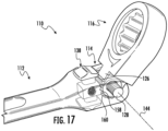
- FIGS. 16-17 side perspective views of the locking mechanism 130 of wrench 110 in the unlocked position (see e.g., FIG. 16 ) and the locked position (see e.g., FIG. 17 ) with the head 116 pivoted is shown according to an exemplary embodiment.
- Head 116 has been pivoted in a counterclockwise direction shown by arrow 176 such that the angle between head 116 and handle 112 has been reduced.
- Head 116 can similarly be pivoted in a clockwise direction, shown by arrow 178 such that the angle between head 116 and handle 112 is increased.
- spring 134 When locking mechanism 130 is moving between the unlocked position and the locked position spring 134 is compressed within locking channel 162. In other words, when ball 164 moves out of one of the first or second recess 163, 165, spring 134 is compressed until ball 164 is repositioned in the other of the first and second recesses 163, 165.
- a tool such as wrench 210
- Wrench 210 is substantially the same as wrench 110 except for the differences discussed herein.
- Applicant has designed a locking mechanism for a tool with a pivoting head that provides for secure locking (i.e., decreased likelihood of accidental actuation).
- tools with pivoting heads typically include locking mechanisms that may be accidentally actuated (e.g., by bumping a switch, etc.).
- Applicant believes using a design with a push button switch and a receiver configured to engage the push button switch reduces the likelihood of accidentally actuating and unlocking the pivot head because the design discussed herein requires pushing the button downward and then sliding the button forward and/or pulling the button backward to lock and/or unlock the pivot head.
- wrench 210 includes a locking mechanism 230 that allows the user to selectably and reversibly lock head 216 in a desired angular position relative to the handle 212.
- Locking mechanism 230 is moveable between a locked position in which the angular position of head 216 relative to handle 212 is fixed and an unlocked position in which head 216 is pivotable about pivot joint 214.
- Locking mechanism 230 is controlled by a switching device or actuator, shown as push button switch 238.
- push button switch 238 includes a receiver 250 that engages head 216 and specifically toothed projection 226. Push button switch 238 can be accessed and/or actuated on one side of handle 212.
- Locking mechanism 230 includes push button switch 238, a biasing component, shown as spring 234, toothed projection 226, and the receiver 250.
- Receiver 250 includes an open section 251 facing push button switch 238 and sized to receive a portion of push button switch 238.
- Handle 212 includes an outer surface 252.
- Outer surface 252 includes a first pair of opposing notches 254 and a second pair of opposing notches 256.
- the first pair of opposing notches 254 are positioned between the second pair of opposing notches 256 and head 216.
- Each pair of opposing notches 254, 256 are positioned on opposite sides of cavity 232 from the opposing notch (i.e., one of each notch 254, 256 is positioned on each side of cavity 232).
- locking mechanism 230 of wrench 210 is at least partially positioned within a cavity 232 in handle 212.
- Push button switch 238 includes an actuating surface 262 extending outward relative to handle 212 and configured to be pushed and/or engaged by a user's finger.
- actuating surface 262 is a planar or flat surface.
- Push button switch 238 further includes a body or engagement portion 264 that is positioned within receiver 250 when push button switch 238 is assembled.
- Spring 234 extends between and engages body portion 264 and an inner surface of open section 251 of receiver 250.
- push button switch 238 includes a channel 276 that receives a portion of spring 234.
- Push button switch 238 further includes opposing projections 266.
- Opposing projections 266 extend in a generally parallel (i.e., parallel plus or minus 10 degrees) direction to pivot axis 244.
- Each of the opposing projections 266 is sized and/or configured to engage with the first pair of opposing notches 254 and/or the second pair of opposing notches 256 to hold or secure push button switch 238 in place relative to handle 212.
- the first direction is generally perpendicular (i.e., 90 degrees plus or minus 10 degrees) to pivot axis 244.
- push button switch 238 When a user wants to pivot head 216, push button switch 238 can be compressed or pushed downward (i.e., toward outer surface 252) such that push button switch 238 can then be moved in a second, rearward direction (i.e., away from head 216) opposite of the first direction.
- push button switch 238 When push button switch 238 is moved in the second direction, opposing projections 266 move from being aligned with the first pair of opposing notches 254 until opposing projections 266 are aligned with the second pair of opposing notches 256 that engage opposing projections 266 and/or push button switch 238 such that push button switch 238 is fixed and head 216 is rotatable. In such a position, there is a gap or space between the plurality of teeth 258 on engagement portion 257 of push button switch 238 and the plurality of teeth 260 of toothed projection 226 (i.e., no engagement).
- FIGS. 22-23 cross-sectional views of wrench 210 are shown with locking mechanism 230 in a locked position and an unlocked position, according to an exemplary embodiment.
- teeth 258 are engaged with grooves between teeth 260 of toothed projection 226 such that head 216 is not pivotable and/or rotatable and spring 234 is in an uncompressed or extended state meaning push button switch 238 is in a fixed position due to engagement with the first pair of opposing notches 254.
- Handle 212 and specifically cavity 232 includes projected portion 268 toward head 216. Handle 212 further includes a middle portion 269 recessed relative to projected portion 268. Middle portion 269 of handle 212 includes an upward facing (i.e., towards head 216) surface 270 that opposes a downward facing (i.e., towards handle 212) surface 272 of push button switch 238 and specifically receiver 250. When push button switch 238 is in a locked position, a gap or space exists between downward facing surface 272 and upward facing surface 270.
- push button switch 238 When push button switch 238 is actuated in the first or second direction, push button switch 238 is translated along the longitudinal axis 274 of handle 212. As shown in FIG. 23 , when locking mechanism 230 is in the unlocked position, teeth 258 are disengaged and/or spaced from the teeth 260 of toothed projection 226 such that head 216 is pivotable and/or rotatable and spring 234 is in an uncompressed or extended state meaning push button switch 238 is in a fixed position. In the unlocked position, at least a portion of receiver 250 is positioned within middle portion 269 of handle 212 such that the gap or space between downward facing surface 272 and upward facing surface 270 is reduced and/or removed.
- FIGS. 24-25 side perspective views of the locking mechanism 230 of wrench 210 in the unlocked position (see e.g., FIG. 24 ) and the locked position (see e.g., FIG. 25 ) with the head 216 pivoted, is shown according to an exemplary embodiment.
- Ratchet head 216 has been pivoted in a counterclockwise direction shown by arrow 278 such that the angle between head 216 and handle 212 has been reduced.
- Head 216 can similarly be pivoted in a clockwise direction, shown by arrow 280 such that the angle between head 216 and handle 212 is increased.
- the term "coupled” means the joining of two components directly or indirectly to one another. Such joining may be stationary in nature or movable in nature. Such joining may be achieved with the two members and any additional intermediate members being integrally formed as a single unitary body with one another or with the two members or the two members and any additional member being attached to one another. Such joining may be permanent in nature or alternatively may be removable or releasable in nature.
Landscapes
- Engineering & Computer Science (AREA)
- Mechanical Engineering (AREA)
- Details Of Spanners, Wrenches, And Screw Drivers And Accessories (AREA)
Abstract
Description
- The present application claims the benefit of and priority to
U.S. Provisional Application No. 63/384,823, filed November 23, 2022 U.S. Provisional Application No. 63/374,660, filed September 6, 2022 - The present invention relates generally to the field of tools. The present invention relates specifically to a tool, such as a ratcheting wrench, with a pivoting head.
- One embodiment of the invention relates to a driving tool. The driving tool includes a handle, a head, a workpiece engagement structure, and a ratchet mechanism. The handle includes a first flange, a second flange, and a cavity positioned between the first flange and the second flange. The head includes a toothed projection extending toward the handle. The workpiece engagement structure is coupled to the head. The ratchet mechanism is supported by the head and coupled to the workpiece engagement structure. The tool further includes a pivot joint positioned between the handle and the head. The pivot joint includes an axle extending along a pivot axis. The axle rotatably couples the head to the handle such that the head is pivotable about the pivot joint to a plurality of angular positions relative to the handle. The tool further includes a locking mechanism positioned within a cavity in the handle. The locking mechanism includes a sliding switch positioned within the cavity. The sliding switch includes an actuating surface extending outward from the handle and configured to be engaged by a user's finger. The sliding switch further includes a plurality of teeth facing the toothed projection of the head. The locking mechanism further includes a biasing component and a ball. The biasing component extends in a generally parallel orientation to the pivot axis and resists movement of the sliding switch. The ball is positioned between the biasing component and an inward facing surface of the handle. The locking mechanism is moveable between a locked position in which the angular position of the head relative to the handle is fixed and an unlocked position in which the head is pivotable about the axis of rotation.
- Another embodiment of the invention relates to a driving tool. The driving tool includes a handle, a head, and a workpiece engagement structure. The handle includes a first flange, a second flange, and a cavity positioned between the first flange and the second flange. The head includes a toothed projection extending toward the handle. The workpiece engagement structure is coupled to the head. The driving tool further includes a pivot joint positioned between the handle and the head such that the head is pivotable about the pivot joint to a plurality of angular positions relative to the handle. A pivot axis extends through the pivot joint and is generally perpendicular to a longitudinal axis of the handle. The driving tool further includes a locking mechanism positioned within the cavity. The locking mechanism includes a switch positioned within the cavity. The switch includes a first actuator extending outward from the handle and configured to be engaged by a user's finger and a plurality of teeth facing the toothed projection of the head. The locking mechanism further includes a biasing component and a ball. The biasing component extends in a generally perpendicular orientation to the longitudinal axis of the handle the pivot axis and resists movement of the switch. The ball is positioned between the biasing component and an inward facing surface of the handle. When the switch is actuated, the switch is translated along the longitudinal axis of the handle. when the switch is actuated toward the head, the biasing component is compressed such that the switch is moveable until the plurality of teeth engage the toothed projection of the head.
- Another embodiment of the invention relates to a driving tool. The driving tool includes a handle, a head, and a workpiece engagement structure. The handle includes a first flange, a second flange, and a cavity positioned between the first flange and the second flange. The head includes a toothed projection extending toward the handle. The workpiece engagement structure is coupled to the head. The driving tool further includes a pivot joint positioned between the handle and the head to rotatably coupled the handle to the head such that the head is pivotable about the pivot joint to a plurality of angular positions relative to the handle. A pivot axis extends through the pivot joint and is generally perpendicular to a longitudinal axis of the handle. The driving tool further includes a locking mechanism that includes a switch. The switch includes an actuator extends outward from the handle and is configured to be engaged by a user's finger. The switch further includes a body portion coupled to the actuator. The body portion includes an upward facing surface that faces toward the head, a downward facing surface that faces toward the handle, and a plurality of teeth on the upward facing surface of the body. The plurality of teeth extend toward the toothed projection of the head. The body portion further includes a locking channel that extends in a generally parallel orientation to the pivot axis. The driving tool further includes a biasing component and a ball. The biasing component is configured to resist movement of the switch. The ball is positioned between the biasing component and an inward facing surface of the handle. When the switch is actuated, the switch is translated along the longitudinal axis of the handle.
- Another embodiment relates to a driving tool. The tool includes a head, a handle, a workpiece engagement structure, and a ratchet mechanism. The workpiece engagement structure is coupled to the head. The ratchet mechanism is supported by the head and coupled to the workpiece engagement structure. The tool further includes a pivot joint positioned between the handle and the head and coupling the head to the body such that head is rotatable about the pivot joint to a plurality of angular positions relative to the handle. The tool further includes a locking mechanism that extends along an axis of rotation of the head. The locking mechanism includes a pin coupling the head to the handle, the pin including an engagement portion and a biasing element that engages the pin and biases the pin along the axis of rotation. The locking mechanism is moveable between a locked position in which the biasing element pushes the engagement portion of the pin into engagement with the head such that the angular position of the head is fixed relative to the body and an unlocked position in which the head is pivotable relative to the body. The pin translates along the axis of rotation into and out of the locked position.
- Additional features and advantages will be set forth in the detailed description which follows, and, in part, will be readily apparent to those skilled in the art from the description or recognized by practicing the embodiments as described in the written description and claims hereof, as well as the appended drawings. It is to be understood that both the foregoing general description and the following detailed description are exemplary.
- The accompanying drawings are included to provide further understanding and are incorporated in and constitute a part of this specification. The drawings illustrate one or more embodiments, and together with the description serve to explain principles and operation of the various embodiments.
- This application will become more fully understood from the following detailed description, taken in conjunction with the accompanying figures, wherein like reference numerals refer to like elements in which:
-
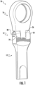
FIG. 1 is a perspective view of a ratchet wrench with a pivoting head, according to an exemplary embodiment. -
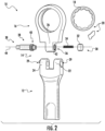
FIG. 2 is an exploded view of the ratchet wrench with the pivoting head ofFIG. 1 , according to an exemplary embodiment. -
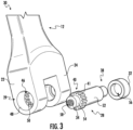
FIG. 3 is a partially exploded view of the ratchet wrench ofFIG. 1 with the pivoting head removed, according to an exemplary embodiment. -
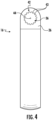
FIG. 4 is side plan view of the pivoting head of the ratchet wrench orFIG. 1 , according to an exemplary embodiment. -
FIG. 5 is a cross-sectional view of the ratchet wrench with the pivoting head ofFIG. 1 with a locking mechanism in a locked position, according to an exemplary embodiment. -
FIG. 6 is a perspective view of the locking mechanism of the ratchet wrench ofFIG. 1 in an unlocked position, according to an exemplary embodiment. -
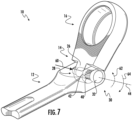
FIG. 7 is a side perspective view of the locking mechanism of the ratchet wrench ofFIG. 1 in the unlocked position with the head pivoted, according to an exemplary embodiment. -
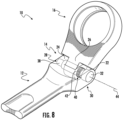
FIG. 8 is a side perspective view of the locking mechanism of the ratchet wrench ofFIG. 1 in the locked position with the head pivoted, according to an exemplary embodiment. -
FIG. 9 is a perspective view of a ratchet wrench with a pivoting head, according to another exemplary embodiment. -
FIG. 10 is a rear perspective view of the pivoting head of the ratchet wrench ofFIG. 9 , according to an exemplary embodiment. -
FIG. 11 is an exploded view of the ratchet wrench with the pivoting head ofFIG. 9 , according to an exemplary embodiment. -
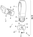
FIG. 12 is an exploded view of a locking mechanism of the ratchet wrench ofFIG. 9 , according to an exemplary embodiment. -
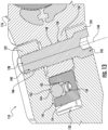
FIG. 13 is a cross-sectional view of the ratchet wrench with the pivoting head ofFIG. 9 with the locking mechanism in a locked position, according to an exemplary embodiment. -
FIG. 14 is a cross-sectional view of the ratchet wrench with the pivoting head ofFIG. 9 with the locking mechanism in a locked position, according to an exemplary embodiment. -
FIG. 15 is a cross-sectional view of the ratchet wrench with the pivoting head ofFIG. 9 with the locking mechanism in an unlocked position, according to an exemplary embodiment. -
FIG. 16 is a side perspective view of the locking mechanism of the ratchet wrench ofFIG. 9 in the unlocked position with the head pivoted, according to an exemplary embodiment. -
FIG. 17 is a side perspective view of the locking mechanism of the ratchet wrench ofFIG. 9 in the locked position with the head pivoted, according to an exemplary embodiment. -
FIG. 18 is a perspective view of a ratchet wrench with a pivoting head, according to another exemplary embodiment. -
FIG. 19 is a rear perspective view of the pivoting head of the ratchet wrench ofFIG. 18 , according to an exemplary embodiment. -
FIG. 20 is an exploded view of the ratchet wrench with the pivoting head ofFIG. 18 , according to an exemplary embodiment. -
FIG. 21 is an exploded view of a locking mechanism of the ratchet wrench ofFIG. 18 , according to an exemplary embodiment. -
FIG. 22 is a cross-sectional view of the ratchet wrench with the pivoting head ofFIG. 18 with the locking mechanism in a locked position, according to an exemplary embodiment. -
FIG. 23 is a cross-sectional view of the ratchet wrench with the pivoting head ofFIG. 18 with the locking mechanism in an unlocked position, according to an exemplary embodiment. -
FIG. 24 is a side perspective view of the locking mechanism of the ratchet wrench ofFIG. 18 in the unlocked position with the head pivoted, according to an exemplary embodiment. -
FIG. 25 is a side perspective view of the locking mechanism of the ratchet wrench ofFIG. 18 in the locked position with the head pivoted, according to an exemplary embodiment. - Referring generally to the figures, various embodiments of a tool with a pivoting head and locking mechanism are shown. As discussed in detail below, Applicant has designed a locking mechanism for a tool with a pivoting head that provides for robust locking operating, increased adjustability in tight spaces and decreased complexity (i.e., fewer components are necessary). In contrast to the tool with a pivoting head discussed herein, tools with pivoting heads typically include locking mechanisms positioned on and/or within the body of the tool. In small or tight spaces this means a user may have difficulty unlocking and pivoting the head and/or handle to use the tool. The design discussed here includes a locking mechanism positioned along an axis of rotation of the pivoting portion of the tool allowing for use in more confined work environments.
- Referring to
FIG. 1 , a tool, such aswrench 10, is shown according to an exemplary embodiment. In the embodiment shown,wrench 10 is a ratchet wrench including a tool body or handle 12, apivot j oint 14 and a pivoting portion, shown ashead 16. In general,pivot j oint 14 is located betweenhandle 12 andhead 16 and allows the user to change the angular position ofhead 16 relative to handle 12. - As will be understood,
head 16 includes a workpiece engagement structure 18 (see e.g.,FIG. 2 ) and aratchet mechanism 20. In generalworkpiece engagement structure 18 may be any structure that allows for engagement of a workpiece (e.g., a fastener, a bolt, a nut, etc.), and handle12 acts as a handle and a lever to apply torque to the workpiece. In specific embodiments,workpiece engagement structure 18 is an open wrench head. In other embodiments,workpiece engagement structure 18 is a variety of other torque applying workpiece engagement structures, such as a screw driver head, a post configured to releasably engage a socket, a closed wrench head, etc. - As will be generally understood, ratchet
mechanism 20 is supported withinhead 16, and coupled toworkpiece engagement structure 18 such thatratchet mechanism 20 provides ratcheting action to workpieceengagement structure 18. In general,ratchet mechanism 20 is a mechanical structure that allows for free or unrestricted rotation ofhandle 12 aroundworkpiece engagement structure 18 in a first direction and allows for restricted or driving rotation ofhandle 12 aroundworkpiece engagement structure 18 in a second direction opposite of the first direction.Wrench 10 may include a selection mechanism that allows the user to select which rotational direction provides driving rotation and which provides free rotation. In a specific embodiment,ratchet mechanism 20 includes a gear structure, one or more pawls and a biasing component. - Referring to
FIG. 1 andFIG. 2 ,wrench 10 includes apivot j oint 14 that allows the user to adjust the angular position ofhead 16 relative to handle 12.Wrench 10 includes flanges orarms handle 12 positioned proximate or adjacent to head 16.Head 16 includes aprojection 26 that is positioned betweenarms pin 28 extends throughopenings 29 througharms projection 26 such thatpin 28 rotatably couples head 16 to handle 12. -
Wrench 10 includes alocking mechanism 30 that allows the user to selectably and reversibly lockhead 16 in a desired angular position relative to thehandle 12. Lockingmechanism 30 is moveable between a locked position in which the angular position ofhead 16 relative to handle 12 is fixed and an unlocked position in which head 16 is pivotable about pivot joint 14. - In general,
locking mechanism 30 includes an end portion, shown asend cap 32, a biasing component, shown asspring 34, achannel 36 extending throughprojection 26 andpin 28. In general, when a user moves and/or pushes an actuatingend 38 ofpin 28, a portion ofpin 28 including external engagement features, shown as teeth orsplines 40 that engage cooperating features, shown asgrooves 42 ofchannel 36 and/orarm 22 move to an unlocked position. In the unlocked position, splines 40 disengage from thegrooves 42 ofchannel 36 ofhead 16, allowinghead 16 to freely pivot aboutpin 28. Then, when a user releases actuatingend 38 ofpin 28spring 34 pushes and/or actuatespin 28 back into to a locked position. In the locked positionedsplines 40 engage thegrooves 42 ofchannel 36 and/orarm 22 ofhandle 12, lockinghead 16 in the desired angular position. - In another specific embodiment, the locking features may be different from splines (i.e., projections). In a specific embodiment, the
pin 28 andsplines 40 are integrally formed from one piece of material. In another specific embodiment, thepin 28 andsplines 40 are integrally formed from one piece of metal material. - Locking
mechanism 30 and specifically pin 28 is positioned and extends along a pivot axis or axis ofrotation 44.Head 16 pivots about axis ofrotation 44. Thepin 28 translates and/or moves along the axis ofrotation 44 into and out of the locked position and as such, the axis of translation is the same as the axis ofrotation 44. In a specific embodiment, splines 40 are radially symmetric about the axis ofrotation 44. As previously discussed, Applicant believes positioning the locking mechanism along the axis of rotation allows for a robust locking mechanism with reduced complexity that has improved functioning in tight spaces because the position allows for actuating the button and/or end ofpin 28 and adjusting the tool head angle with limited movement of a user's hand. - Referring to
FIG. 3 , a partially exploded perspective view oflocking mechanism 30 withhead 16 removed is shown, according to an exemplary embodiment. Achannel 46 extends between opposingopenings 29 of the engagement end ofhandle 12 througharms outer portion 48 ofchannel 46 inarm 22 is configured to receiveend cap 32. An inner portion (i.e., adjacent toprojection 26 whenwrench 10 is assembled) ofchannel 46 includes cooperating features, shown asgrooves 50. -
Pin 28 includes apivot portion 52 positioned between actuatingend 38 and splines 40.Pin 28 further includes a biasingend 54 opposing actuatingend 38. Whenwrench 10 and specifically lockingmechanism 30 is assembled, biasingend 54 ofpin 28 is received with an internally facing (i.e., towardprojection 26 and grooves 50)recess 56 ofend cap 32. Biasingend 54 ofpin 28 includes achannel 58.Channel 58 is configured to receivespring 34 and extendspast splines 40 into thepivot portion 52 of pin 28 (see e.g.,FIG. 5 ). - In various specific embodiments, the engagement portion of
pin 28 including an outermost surface withsplines 40 has a greater dimension (i.e., distance from axis ofrotation 44 to outermost surface) than an outer dimension of thepivot portion 52. In a specific embodiment, the outer dimension ofpivot portion 52 is greater than an outer dimension of biasingend 54 and the outer dimension of biasingend 54 is greater than an outer dimension of actuatingend 38 ofpin 28. In a specific embodiment, the dimension is a diameter. - Referring to
FIG. 4 , a side plan view ofhead 16 is shown according to an exemplary embodiment.Channel 36 extends throughprojection 26 ofhead 16 along the axis ofrotation 44.Channel 36 includes engagement features, shown as teeth orsplines 43 configured to engage cooperating features, shown asgrooves 41 on pin 28 (see e.g.,FIG. 3 ).Splines 43 ofchannel 36 extend inward fromhead 16 toward axis ofrotation 44. - Referring to
FIG. 5 , a cross-sectional view ofwrench 10 is shown withlocking mechanism 30 in a locked position, according to an exemplary embodiment. As shown inFIG. 5 , when lockingmechanism 30 is in the locked position, splines 40 are engaged withgrooves 42 ofprojection 26 such thathead 16 is not pivotable and/or rotatable andspring 34 is in an uncompressed state. - Referring to
FIGS. 6-7 , perspective views ofwrench 10 are shown withlocking mechanism 30 in an unlocked position, according to an exemplary embodiment. When a user pushes actuatingend 38 of pin 28 a force is provided as shown byarrow 60. Thesplines 40 disengage from thegrooves 42 ofprojection 26 andgrooves 50 ofarm 22 and the space betweenpin 28 andend cap 32 is decreased. In such a position,spring 34 is compressed withinchannel 58. Withpivot portion 52 positioned withinchannel 36 ofprojection 26,pivot portion 52 is rotatable withinprojection 26 such thathead 16 is pivotable about axis ofrotation 44. - Referring to
FIG. 7 , a side perspective view of thelocking mechanism 30 of thewrench 10 in the unlocked position with thehead 16 pivoted is shown according to an exemplary embodiment.Ratchet head 16 has been pivoted in a counterclockwise direction shown byarrow 62 such that the angle betweenhead 16 and handle 12 has been reduced.Head 16 can similarly be pivoted in a clockwise direction, shown byarrow 64 such that the angle betweenhead 16 and handle 12 is increased. In a specific embodiment,head 16 is pivotable relative to handle 12. - Referring to
FIG. 8 , a side perspective view of thelocking mechanism 30 of thewrench 10 in the locked position with thehead 16 pivoted is shown according to an exemplary embodiment. When a user does not push actuatingend 38 ofpin 28,spring 34 which had been compressedpushes actuating end 38 back toward opening 29 ofarm 24. Thespring 34 extends along the axis ofrotation 44 between thepin 28 and theend cap 32 such that thespring 34 provides a force that biases thepin 28 away from theend cap 32 toward engagement with thehead 16.Splines 40 reengage withgrooves 42 ofchannel 36 ofprojection 26 and/orgrooves 50 ofchannel 46 ofarm 22. This engagement between thechannel grooves splines 40 ofpin 28 locks thetool head 16 at the selected, pivoted angle. - Referring to
FIGS. 9-15 and as discussed in greater detail below, Applicant has designed additional embodiments of a locking mechanism for a tool with a pivoting head that provides for robust locking operating, increased adjustability in tight spaces and decreased complexity (i.e., fewer components are necessary). In contrast to the tool with a pivoting head discussed herein, tools with pivoting heads typically include locking mechanisms including numerous components that are difficult and/or expensive to manufacture. In a specific embodiment, the design discussed here includes a locking mechanism with a slider or button that is a single piece or component. Further, tools with pivoting heads typically have problems in small or tight spaces because a user may have difficulty unlocking and pivoting the head and/or handle to use the tool. The design discussed here includes a locking mechanism that can be easily actuated allowing for use in more confined work environments. In a specific embodiment, the slider or button is accessible from both sides allowing for the tool to be unlocked and pivoted even in confined spaces. - Referring to
FIG. 9 , a tool, such aswrench 110, is shown according to an exemplary embodiment. In the embodiment shown,wrench 110 is a combination wrench including atool handle 112, an open wrench end 113 and a ratchet head orend 116.Head 116 is formed from a generally ring-shaped portion ofwrench 110 that surrounds and supportsworkpiece engagement surface 118.Wrench 110 further includes a pivot joint 114 located betweenhandle 112 andhead 116 and allows the user to change the angular position ofhead 116 relative to handle 112.Head 116 includes the workpiece engagement structure 118 (see e.g.,FIG. 11 ) and aratchet mechanism 120.Ratchet mechanism 120 is substantially the same asratchet mechanism 20 except for the differences discussed herein. In a specific embodiment,ratchet mechanism 120 includes a gear structure, one or more pawls and one or more biasing components. - Referring to
FIGS. 9-10 ,wrench 110 and specifically pivot joint 114 includes flanges orarms handle 112 positioned proximate or adjacent to head 116.Head 116 includes atoothed projection 126 that is positioned betweenarms fastener 128 extends throughopenings 129 througharms toothed projection 126 such thatfastener 128 rotatably couples head 116 to handle 112. In a specific embodiment,fastener 128 is socket head cap screw. -
Wrench 110 includes alocking mechanism 130 that allows the user to selectably and reversibly lockhead 116 in a desired angular position relative to thehandle 112.Locking mechanism 130 is moveable between a locked position in which the angular position ofhead 116 relative to handle 112 is fixed and an unlocked position in which head 116 is pivotable about pivot joint 114.Locking mechanism 130 is controlled by a switching device or actuator, shown as slidingswitch 138. In a specific embodiment, slidingswitch 138 is a single component. In another specific embodiment, slidingswitch 138 is integrally formed from one piece of material. In other words, slidingswitch 138 is a single, integral component. In various embodiment, slidingswitch 138 is formed from a metal material or a polymer material. Slidingswitch 138 can be accessed and/or actuated on at least one side ofhandle 112. In a specific embodiment, slidingswitch 138 can be actuated or accessed from both sides (i.e., upper and lower sides) ofhandle 112 allowing for use oflocking mechanism 130 andpivotable head 116 in tight or confined spaces. - Referring to
FIG. 11 , an exploded view ofwrench 110 is shown according to an exemplary embodiment.Locking mechanism 130 includes slidingswitch 138, a biasing component, shown asspring 134,toothed projection 126, and aball 164.Fastener 128 is positioned and extends along a pivot axis or axis ofrotation 144.Head 116 pivots aboutpivot axis 144.Fastener 128 includes apivot portion 148 positioned between a threadedend 140 and asocket cap end 142. Whenwrench 110 is assembled, threadedend 140 offastener 128 is received with achannel 146 extending througharm 122.Channel 146 includes threading to couplefastener 128 to handle 112. Ashead 116 is pivoted, achannel 136 extending through toothed projection rotates or moves relative to pivotportion 148 offastener 128. - Referring to
FIGS. 12-13 , details of lockingmechanism 130 ofwrench 110 are shown, according to an exemplary embodiment. In general,locking mechanism 130 is at least partially positioned within acavity 132 inhandle 112.Cavity 132 is positioned betweenarms switch 138 includes anactuating surface 150 extending outward fromhandle 112 and configured to be pushed and/or engaged by a user's finger. In a specific embodiment, slidingswitch 138 includes a second, opposing actuatingsurface 152 that extends outward from an opposing side ofhandle 112 from actuatingsurface 150 such thatlocking mechanism 130 can be accessed from either side ofhandle 112. - A
body portion 154 of slidingswitch 138 extends between and connects opposing actuatingsurfaces Body portion 154 includes anengagement portion 156 with a plurality ofteeth 158. The plurality ofteeth 158 extend toward and/or facetoothed projection 126 and the plurality ofteeth 160 on thetoothed projection 126. -
Body portion 154 further includes a lockingchannel 162 that extends in a generally parallel orientation (i.e., parallel plus or minus 10 degrees) to pivotaxis 144. When lockingmechanism 130 is assembled,spring 134 is positioned within lockingchannel 162 and extends in a generally parallel (i.e., parallel plus or minus 10 degrees) orientation to pivotaxis 144.Ball 164 is at least partially received within lockingchannel 162 and configured to engage an end ofspring 134 and a surface ofhandle 112. Specifically, at least one ofarms surface 161 includes a first orupper recess 163 and a second orlower recess 165.First recess 163 is positioned betweenhead 116 andsecond recess 165. First andsecond recesses ball 164. In other words, first andsecond recesses ball 164 such that first andsecond recesses ball 164 and therefore resist movement of slidingswitch 138. - In general, when
wrench 110 is in an unlocked position and a user moves and/or pushes slidingswitch 138 in a first, forward direction (i.e., towards head 116),ball 164 moves out ofsecond recess 165compressing spring 134 untilball 164 engagesfirst recess 163 which allowsspring 134 to expand and/or uncompress. Whenball 164 is positioned withinfirst recess 163, the plurality ofteeth 158 of slidingswitch 138 are positioned such that theteeth 158 engage withteeth 160 oftoothed projection 126, locking or fixinghead 116 in place. The first direction is generally perpendicular (i.e., 90 degrees plus or minus 10 degrees) to pivotaxis 144. - When a user wants to pivot
head 116, slidingswitch 138 is moved in a second, rearward direction (i.e., away from head 116) opposite of the first direction. When slidingswitch 138 is moved in the second direction,ball 164 moves out offirst recess 163compressing spring 134 untilball 164 engagessecond recess 165 which holds the slidingswitch 138 in place (i.e., resists movement of sliding switch 138). In such a position, there is a gap or space between the plurality ofteeth 158 of slidingswitch 138 and the plurality ofteeth 160 oftoothed projection 126 such thathead 116 is unlocked and pivotable. - Referring to
FIGS. 14-15 , cross-sectional views ofwrench 110 are shown withlocking mechanism 130 in a locked position and an unlocked position, according to an exemplary embodiment. As shown inFIG. 14 , when lockingmechanism 130 is in the locked position,teeth 158 are engaged with grooves betweenteeth 160 oftoothed projection 126 such thathead 116 is not pivotable and/or rotatable andspring 134 is in an uncompressed or extended statemeaning sliding switch 138 is in a fixed position. Slidingswitch 138 is moveable along alongitudinal axis 174 ofwrench 110. - Sliding
switch 138 further includes a recessedsection 166. In various specific embodiments, slidingswitch 138 includes a pair of recessedsections 166. Each recessedsection 166 is positioned between anactuating surface body portion 154. Handle 112 includes a projectedportion 168 extending towardhead 116, the projectedportion 168 at least partially definescavity 132. In various specific embodiments, handle 112 includes a pair or projectedportions 168. Projectedportion 168 extends between and connectsflanges - Handle 112 further includes a
middle portion 169 recessed relative to projectedportion 168.Middle portion 169 ofhandle 112 includes an upward facing (i.e., towards head 116)surface 170 that opposes a downward facing (i.e., towards handle 112)surface 172 of slidingswitch 138 and/orbody portion 154. When slidingswitch 138 is in a locked position, a gap or space exists between downward facingsurface 172 and upward facingsurface 170 ofhandle 112. - When sliding
switch 138 is actuated in the first or second direction, slidingswitch 138 is translated along thelongitudinal axis 174 ofhandle 112. As shown inFIG. 15 , when lockingmechanism 130 is in the unlocked position,teeth 158 are disengaged and/or spaced from theteeth 160 oftoothed projection 126 such thathead 116 is pivotable and/or rotatable andspring 134 is in an uncompressed or extended state meaning (i.e., slidingswitch 138 is in a fixed position). In the unlocked position, projectedportion 168 of handle is positioned withinrecesses 166 of slidingswitch 138 such that the gap or space between downward facingsurface 172 and upward facingsurface 170 is reduced and/or removed. - Referring to
FIGS. 16-17 , side perspective views of thelocking mechanism 130 ofwrench 110 in the unlocked position (see e.g.,FIG. 16 ) and the locked position (see e.g.,FIG. 17 ) with thehead 116 pivoted is shown according to an exemplary embodiment.Head 116 has been pivoted in a counterclockwise direction shown byarrow 176 such that the angle betweenhead 116 and handle 112 has been reduced.Head 116 can similarly be pivoted in a clockwise direction, shown byarrow 178 such that the angle betweenhead 116 and handle 112 is increased. - When locking
mechanism 130 is moving between the unlocked position and the lockedposition spring 134 is compressed within lockingchannel 162. In other words, whenball 164 moves out of one of the first orsecond recess spring 134 is compressed untilball 164 is repositioned in the other of the first andsecond recesses - Referring to
FIG. 18 , a tool, such aswrench 210, is shown according to an exemplary embodiment.Wrench 210 is substantially the same aswrench 110 except for the differences discussed herein. Applicant has designed a locking mechanism for a tool with a pivoting head that provides for secure locking (i.e., decreased likelihood of accidental actuation). In contrast to the tool with a pivoting head discussed herein, tools with pivoting heads typically include locking mechanisms that may be accidentally actuated (e.g., by bumping a switch, etc.). Applicant believes using a design with a push button switch and a receiver configured to engage the push button switch reduces the likelihood of accidentally actuating and unlocking the pivot head because the design discussed herein requires pushing the button downward and then sliding the button forward and/or pulling the button backward to lock and/or unlock the pivot head. - Referring to
FIGS. 18-19 ,wrench 210 includes alocking mechanism 230 that allows the user to selectably and reversibly lockhead 216 in a desired angular position relative to thehandle 212.Locking mechanism 230 is moveable between a locked position in which the angular position ofhead 216 relative to handle 212 is fixed and an unlocked position in which head 216 is pivotable about pivot joint 214.Locking mechanism 230 is controlled by a switching device or actuator, shown aspush button switch 238. As will be described in greater detail below,push button switch 238 includes areceiver 250 that engageshead 216 and specificallytoothed projection 226. Pushbutton switch 238 can be accessed and/or actuated on one side ofhandle 212. - Referring to
FIG. 20 , an exploded view ofwrench 210 is shown according to an exemplary embodiment.Locking mechanism 230 includespush button switch 238, a biasing component, shown asspring 234,toothed projection 226, and thereceiver 250.Receiver 250 includes anopen section 251 facingpush button switch 238 and sized to receive a portion ofpush button switch 238. - Handle 212 includes an
outer surface 252.Outer surface 252 includes a first pair of opposingnotches 254 and a second pair of opposingnotches 256. The first pair of opposingnotches 254 are positioned between the second pair of opposingnotches 256 andhead 216. Each pair of opposingnotches cavity 232 from the opposing notch (i.e., one of eachnotch - Referring to
FIG. 21 , details of lockingmechanism 230 ofwrench 210 are shown, according to an exemplary embodiment. In general,locking mechanism 230 is at least partially positioned within acavity 232 inhandle 212. Pushbutton switch 238 includes anactuating surface 262 extending outward relative to handle 212 and configured to be pushed and/or engaged by a user's finger. In a specific embodiment, actuatingsurface 262 is a planar or flat surface. Pushbutton switch 238 further includes a body orengagement portion 264 that is positioned withinreceiver 250 whenpush button switch 238 is assembled.Spring 234 extends between and engagesbody portion 264 and an inner surface ofopen section 251 ofreceiver 250. In a specific embodiment,push button switch 238 includes achannel 276 that receives a portion ofspring 234. Pushbutton switch 238 further includes opposingprojections 266. Opposingprojections 266 extend in a generally parallel (i.e., parallel plus or minus 10 degrees) direction to pivotaxis 244. Each of the opposingprojections 266 is sized and/or configured to engage with the first pair of opposingnotches 254 and/or the second pair of opposingnotches 256 to hold or securepush button switch 238 in place relative to handle 212. - In general, when
wrench 210 is in an unlocked position and a user pushes downward (i.e., toward outer surface 252) onpush button switch 238,spring 234 is compressed andopposing projections 266 move downward from an engaged position with the second pair of opposingnotches 256 to a disengaged position. A user can then move (i.e., translate)push button switch 238 in a first, forward direction (i.e., towards head 216), until opposingprojections 266 are aligned with the first pair of opposingnotches 254. A user can then releasepush button switch 238 which allowsspring 134 to expand andopposing projections 266 are positioned such that the opposing projections engage with the first pair of opposingnotches 254, locking or fixingpush button switch 238 in place. In such a position, there is no gap or space between a plurality ofteeth 258 on anengagement portion 257 ofpush button switch 238 and the plurality ofteeth 260 oftoothed projection 226, locking or fixinghead 216 in place relative to handle 212. The first direction is generally perpendicular (i.e., 90 degrees plus or minus 10 degrees) to pivotaxis 244. - When a user wants to pivot
head 216,push button switch 238 can be compressed or pushed downward (i.e., toward outer surface 252) such thatpush button switch 238 can then be moved in a second, rearward direction (i.e., away from head 216) opposite of the first direction. Whenpush button switch 238 is moved in the second direction, opposingprojections 266 move from being aligned with the first pair of opposingnotches 254 until opposingprojections 266 are aligned with the second pair of opposingnotches 256 that engage opposingprojections 266 and/or pushbutton switch 238 such thatpush button switch 238 is fixed andhead 216 is rotatable. In such a position, there is a gap or space between the plurality ofteeth 258 onengagement portion 257 ofpush button switch 238 and the plurality ofteeth 260 of toothed projection 226 (i.e., no engagement). - Referring to
FIGS. 22-23 , cross-sectional views ofwrench 210 are shown withlocking mechanism 230 in a locked position and an unlocked position, according to an exemplary embodiment. As shown inFIG. 22 , when lockingmechanism 230 is in the locked position,teeth 258 are engaged with grooves betweenteeth 260 oftoothed projection 226 such thathead 216 is not pivotable and/or rotatable andspring 234 is in an uncompressed or extended state meaningpush button switch 238 is in a fixed position due to engagement with the first pair of opposingnotches 254. - Handle 212 and specifically
cavity 232 includes projectedportion 268 towardhead 216. Handle 212 further includes amiddle portion 269 recessed relative to projectedportion 268.Middle portion 269 ofhandle 212 includes an upward facing (i.e., towards head 216)surface 270 that opposes a downward facing (i.e., towards handle 212)surface 272 ofpush button switch 238 and specificallyreceiver 250. Whenpush button switch 238 is in a locked position, a gap or space exists between downward facingsurface 272 and upward facingsurface 270. - When
push button switch 238 is actuated in the first or second direction,push button switch 238 is translated along thelongitudinal axis 274 ofhandle 212. As shown inFIG. 23 , when lockingmechanism 230 is in the unlocked position,teeth 258 are disengaged and/or spaced from theteeth 260 oftoothed projection 226 such thathead 216 is pivotable and/or rotatable andspring 234 is in an uncompressed or extended state meaningpush button switch 238 is in a fixed position. In the unlocked position, at least a portion ofreceiver 250 is positioned withinmiddle portion 269 ofhandle 212 such that the gap or space between downward facingsurface 272 and upward facingsurface 270 is reduced and/or removed. - Referring to
FIGS. 24-25 , side perspective views of thelocking mechanism 230 ofwrench 210 in the unlocked position (see e.g.,FIG. 24 ) and the locked position (see e.g.,FIG. 25 ) with thehead 216 pivoted, is shown according to an exemplary embodiment.Ratchet head 216 has been pivoted in a counterclockwise direction shown byarrow 278 such that the angle betweenhead 216 and handle 212 has been reduced.Head 216 can similarly be pivoted in a clockwise direction, shown byarrow 280 such that the angle betweenhead 216 and handle 212 is increased. - It should be understood that while the disclosure herein relates primarily to ratchet wrenches, the locking member embodiments discussed herein can be used with a variety of tools with pivoting heads or other portions, such as handles.
- It should be understood that the figures illustrate the exemplary embodiments in detail, and it should be understood that the present application is not limited to the details or methodology set forth in the description or illustrated in the figures. It should also be understood that the terminology is for the purpose of description only and should not be regarded as limiting.
- Further modifications and alternative embodiments of various aspects of the invention will be apparent to those skilled in the art in view of this description. Accordingly, this description is to be construed as illustrative only. The construction and arrangements, shown in the various exemplary embodiments, are illustrative only. Although only a few embodiments have been described in detail in this disclosure, many modifications are possible (e.g., variations in sizes, dimensions, structures, shapes and proportions of the various elements, values of parameters, mounting arrangements, use of materials, colors, orientations, etc.) without materially departing from the novel teachings and advantages of the subject matter described herein. Some elements shown as integrally formed may be constructed of multiple parts or elements, the position of elements may be reversed or otherwise varied, and the nature or number of discrete elements or positions may be altered or varied. The order or sequence of any process, logical algorithm, or method steps may be varied or re-sequenced according to alternative embodiments. Other substitutions, modifications, changes and omissions may also be made in the design, operating conditions and arrangement of the various exemplary embodiments without departing from the scope of the present invention.
- Unless otherwise expressly stated, it is in no way intended that any method set forth herein be construed as requiring that its steps be performed in a specific order. Accordingly, where a method claim does not actually recite an order to be followed by its steps or it is not otherwise specifically stated in the claims or descriptions that the steps are to be limited to a specific order, it is in no way intended that any particular order be inferred. In addition, as used herein, the article "a" is intended to include one or more component or element, and is not intended to be construed as meaning only one. As used herein, "rigidly coupled" refers to two components being coupled in a manner such that the components move together in a fixed positional relationship when acted upon by a force.
- For purposes of this disclosure, the term "coupled" means the joining of two components directly or indirectly to one another. Such joining may be stationary in nature or movable in nature. Such joining may be achieved with the two members and any additional intermediate members being integrally formed as a single unitary body with one another or with the two members or the two members and any additional member being attached to one another. Such joining may be permanent in nature or alternatively may be removable or releasable in nature.
- While the current application recites particular combinations of features in the claims appended hereto, various embodiments of the invention relate to any combination of any of the features described herein whether or not such combination is currently claimed, and any such combination of features may be claimed in this or future applications. Any of the features, elements, or components of any of the exemplary embodiments discussed above may be used alone or in combination with any of the features, elements, or components of any of the other embodiments discussed above.
Claims (20)
- A driving tool, comprising:a handle comprising:a first flange;a second flange; anda cavity positioned between the first flange and the second flange;a head, the head including a toothed projection extending toward the handle;a workpiece engagement structure coupled to the head;a ratchet mechanism supported by the head and coupled to the workpiece engagement structure;a pivot joint positioned between the handle and the head, the pivot joint comprising:
an axle extending along a pivot axis, the axle rotatably coupling the head to the handle such that the head is pivotable about the pivot joint to a plurality of angular positions relative to the handle; anda locking mechanism positioned within the cavity, the locking mechanism comprising:a sliding switch positioned within the cavity, the sliding switch comprising:an actuating surface extending outward from the handle and configured to be engaged by a user's finger; anda plurality of teeth facing the toothed projection of the head;a biasing component extending in a generally parallel orientation to the pivot axis, the biasing component resisting movement of the sliding switch; anda ball positioned between the biasing component and an inward facing surface of the handle;wherein the locking mechanism is moveable between a locked position in which the angular position of the head relative to the handle is fixed and an unlocked position in which the head is pivotable about the pivot joint. - The driving tool of claim 1, the sliding switch further comprising a second, opposing actuating surface that extends outward from an opposing side of handle from the actuating surface such that locking mechanism is accessible from either side of the handle.
- The driving tool of claim 2, the sliding switch further comprising a body portion extending between and connecting the actuating surface and the second actuating surface.
- The driving tool of claim 3, wherein the body portion comprises a locking channel extending in a generally parallel orientation to the pivot axis.
- The driving tool of claim 1, wherein the inward facing surface of the handle is positioned on the first flange.
- The driving tool of claim 1, further comprising a first recess and a second recess, wherein the first recess is positioned between the second recess and the head.
- The driving tool of claim 6, wherein the first recess and second recess are configured to engage the ball and resist movement of the ball.
- The driving tool of claim 6, wherein the first recess and second recess are configured to receive the ball and resist movement of the sliding switch.
- The driving tool of claim 1, wherein the sliding switch is a single, integral component.
- A driving tool comprising:a handle comprising:a first flange;a second flange; anda cavity positioned between the first flange and the second flange;a head, the head including a toothed projection extending toward the handle;a workpiece engagement structure coupled to the head;a pivot joint positioned between the handle and the head to rotatably couple the head to the handle such that the head is pivotable about the pivot joint to a plurality of angular positions relative to the handle;a pivot axis extending through the pivot joint, the pivot axis generally perpendicular to a longitudinal axis of the handle; anda locking mechanism positioned within the cavity, the locking mechanism comprising:a switch positioned within the cavity, the switch comprising:a first actuator extending outward from the handle and configured to be engaged by a user's finger; anda plurality of teeth facing the toothed projection of the head;a biasing component extending in a generally perpendicular orientation to the longitudinal axis of the handle, the biasing component resisting movement of the switch; anda ball positioned between the biasing component and an inward facing surface of the handle;wherein, when the switch is actuated, the switch is translated along the longitudinal axis of the handle;wherein, when the switch is actuated toward the head, the biasing component is compressed such that the switch is moveable until the plurality of teeth engage the toothed projection of the head.
- The driving tool of claim 10, wherein, when the switch is actuated toward the handle, the biasing component is compressed such that the switch is moveable until the switch engages an upward facing surface of the cavity.
- The driving tool of claim 10, the switch further comprising a second, opposing actuator that extends outward from an opposing side of the handle from the first actuator.
- The driving tool of claim 10, wherein, when the locking mechanism is in an unlocked position, the plurality of teeth are disengaged from the toothed projection of the head and the biasing component is in an uncompressed state.
- The driving tool of claim 10, wherein, when the locking mechanism is in a locked position, the plurality of teeth are engaged with the toothed projection of the head and the biasing component is in an uncompressed state.
- The driving tool of claim 11, wherein the inward facing surface of the handle is positioned on one of the first flange and the second flange, and wherein the inward facing surface includes a first recess and a second recess.
- The driving tool of claim 15, wherein the first recess and the second recess are configured to receive the ball and resist movement of the ball.
- A driving tool comprising:a handle comprising:a first flange;a second flange; anda cavity positioned between the first flange and the second flange;a head, the head including a toothed projection extending toward the handle;a workpiece engagement structure coupled to the head;a pivot joint positioned between the handle and the head to rotatably couple the head to the handle such that the head is pivotable about the pivot joint to a plurality of angular positions relative to the handle;a pivot axis extending through the pivot joint, the pivot axis generally perpendicular to a longitudinal axis of the handle; anda locking mechanism, the locking mechanism comprising:a switch, the switch comprising:an actuator extending outward from the handle and configured to be engaged by a user's finger; anda body portion coupled to the actuator, the body portion comprising:an upward facing surface, the upward facing surface facing toward the head;a downward facing surface, the downward facing surface facing toward the handle;a plurality of teeth on the upward facing surface of the body portion, the plurality of teeth extending toward the toothed projection of the head; anda locking channel extending in a generally parallel orientation to the pivot axis;a biasing component configured to resists movement of the switch; anda ball positioned between the biasing component and an inward facing surface of the handle;wherein, when the switch is actuated, the switch is translated along the longitudinal axis of the handle.
- The driving tool of claim 17, the switch further comprising a recessed section positioned between the actuator and the body portion, the recessed section facing toward the handle.
- The driving tool of claim 18, the handle further comprising:a projected portion extending toward the head; anda middle portion recessed relative to the projected portion, the middle portion including an upward facing surface that opposes the downward facing surface of the body portion;wherein the projected portion of handle is positionable within the recessed section of the switch when the plurality of teeth are disengaged from the toothed projection of the head.
- The driving tool of claim of 17, wherein the biasing component extends in a generally perpendicular orientation to the longitudinal axis of the handle.
Applications Claiming Priority (3)
| Application Number | Priority Date | Filing Date | Title |
|---|---|---|---|
| US202263374660P | 2022-09-06 | 2022-09-06 | |
| US202263384823P | 2022-11-23 | 2022-11-23 | |
| US18/360,585 US12703069B2 (en) | 2022-09-06 | 2023-07-27 | Tool with pivoting portion and locking mechanism |
Publications (1)
| Publication Number | Publication Date |
|---|---|
| EP4371708A1 true EP4371708A1 (en) | 2024-05-22 |
Family
ID=87845631
Family Applications (1)
| Application Number | Title | Priority Date | Filing Date |
|---|---|---|---|
| EP23193462.1A Pending EP4371708A1 (en) | 2022-09-06 | 2023-08-25 | Tool with pivoting portion and locking mechanism |
Country Status (1)
| Country | Link |
|---|---|
| EP (1) | EP4371708A1 (en) |
Citations (3)
| Publication number | Priority date | Publication date | Assignee | Title |
|---|---|---|---|---|
| CN203495841U (en) * | 2012-09-28 | 2014-03-26 | 优钢机械股份有限公司 | Angle adjustment structure for ratchet wrench |
| WO2016081543A1 (en) * | 2014-11-20 | 2016-05-26 | Js Products, Inc. | Hand tool having a head which is position-adjustable and lockable relative to a handle |
| US20160361801A1 (en) * | 2015-06-12 | 2016-12-15 | Yeo - Ming Wang | Braking structure of ratchet wrench |
-
2023
- 2023-08-25 EP EP23193462.1A patent/EP4371708A1/en active Pending
Patent Citations (3)
| Publication number | Priority date | Publication date | Assignee | Title |
|---|---|---|---|---|
| CN203495841U (en) * | 2012-09-28 | 2014-03-26 | 优钢机械股份有限公司 | Angle adjustment structure for ratchet wrench |
| WO2016081543A1 (en) * | 2014-11-20 | 2016-05-26 | Js Products, Inc. | Hand tool having a head which is position-adjustable and lockable relative to a handle |
| US20160361801A1 (en) * | 2015-06-12 | 2016-12-15 | Yeo - Ming Wang | Braking structure of ratchet wrench |
Similar Documents
| Publication | Publication Date | Title |
|---|---|---|
| US20240075596A1 (en) | Tool with Pivoting Portion and Locking Mechanism | |
| EP1852222B1 (en) | Locking flex-head ratchet wrench | |
| US4903554A (en) | Reversible ratchet wrench with thin head construction | |
| US4631988A (en) | Reversible ratchet wrench including detent mechanism | |
| AU2024200368B2 (en) | Dual pawl ratchet mechanism | |
| TWI732469B (en) | Folding knife with locking mechanism | |
| US6848344B2 (en) | Articulating wrench assembly | |
| US6993998B1 (en) | Wrench having angle adjustable handle | |
| US12403569B2 (en) | Wrench with work piece locking mechanism | |
| US20240261942A1 (en) | Tool with Pivoting Portion and Locking Mechanism | |
| AU2017263262B2 (en) | Adjustable wrench | |
| AU776080C (en) | Reversible ratchet with remote reversing operating mechanism | |
| EP4385661B1 (en) | Reversible ratchet mechanism | |
| AU2024201440B2 (en) | Ratchet flex joint locking mechanism | |
| CN116867610A (en) | Hand tool with slide adjustment for locking flexible head | |
| US20250262726A1 (en) | Tool with Pivoting Head | |
| US20240100659A1 (en) | Wrenches | |
| EP4393647A1 (en) | Wrench | |
| US20060260431A1 (en) | Window handle | |
| CN117681140A (en) | Reversible ratchet mechanism | |
| US20260097472A1 (en) | Pivoting driver | |
| EP0203915B1 (en) | Reversible ratchet wrench | |
| HK40123029A (en) | Ratchet flex joint locking mechanism | |
| WO2026008249A1 (en) | A hand tool |
Legal Events
| Date | Code | Title | Description |
|---|---|---|---|
| PUAI | Public reference made under article 153(3) epc to a published international application that has entered the european phase |
Free format text: ORIGINAL CODE: 0009012 |
|
| STAA | Information on the status of an ep patent application or granted ep patent |
Free format text: STATUS: THE APPLICATION HAS BEEN PUBLISHED |
|
| AK | Designated contracting states |
Kind code of ref document: A1 Designated state(s): AL AT BE BG CH CY CZ DE DK EE ES FI FR GB GR HR HU IE IS IT LI LT LU LV MC ME MK MT NL NO PL PT RO RS SE SI SK SM TR |
|
| STAA | Information on the status of an ep patent application or granted ep patent |
Free format text: STATUS: REQUEST FOR EXAMINATION WAS MADE |
|
| 17P | Request for examination filed |
Effective date: 20241121 |
|
| RBV | Designated contracting states (corrected) |
Designated state(s): AL AT BE BG CH CY CZ DE DK EE ES FI FR GB GR HR HU IE IS IT LI LT LU LV MC ME MK MT NL NO PL PT RO RS SE SI SK SM TR |
|
| STAA | Information on the status of an ep patent application or granted ep patent |
Free format text: STATUS: EXAMINATION IS IN PROGRESS |
|
| 17Q | First examination report despatched |
Effective date: 20251121 |