EP4371700A1 - Method of processing a cmc airfoil and used fixture - Google Patents
Method of processing a cmc airfoil and used fixture Download PDFInfo
- Publication number
- EP4371700A1 EP4371700A1 EP23211307.6A EP23211307A EP4371700A1 EP 4371700 A1 EP4371700 A1 EP 4371700A1 EP 23211307 A EP23211307 A EP 23211307A EP 4371700 A1 EP4371700 A1 EP 4371700A1
- Authority
- EP
- European Patent Office
- Prior art keywords
- cavity
- fixture
- fiber preform
- trailing edge
- drilling
- Prior art date
- Legal status (The legal status is an assumption and is not a legal conclusion. Google has not performed a legal analysis and makes no representation as to the accuracy of the status listed.)
- Granted
Links
Images



Classifications
-
- C—CHEMISTRY; METALLURGY
- C23—COATING METALLIC MATERIAL; COATING MATERIAL WITH METALLIC MATERIAL; CHEMICAL SURFACE TREATMENT; DIFFUSION TREATMENT OF METALLIC MATERIAL; COATING BY VACUUM EVAPORATION, BY SPUTTERING, BY ION IMPLANTATION OR BY CHEMICAL VAPOUR DEPOSITION, IN GENERAL; INHIBITING CORROSION OF METALLIC MATERIAL OR INCRUSTATION IN GENERAL
- C23C—COATING METALLIC MATERIAL; COATING MATERIAL WITH METALLIC MATERIAL; SURFACE TREATMENT OF METALLIC MATERIAL BY DIFFUSION INTO THE SURFACE, BY CHEMICAL CONVERSION OR SUBSTITUTION; COATING BY VACUUM EVAPORATION, BY SPUTTERING, BY ION IMPLANTATION OR BY CHEMICAL VAPOUR DEPOSITION, IN GENERAL
- C23C16/00—Chemical coating by decomposition of gaseous compounds, without leaving reaction products of surface material in the coating, i.e. chemical vapour deposition [CVD] processes
- C23C16/22—Chemical coating by decomposition of gaseous compounds, without leaving reaction products of surface material in the coating, i.e. chemical vapour deposition [CVD] processes characterised by the deposition of inorganic material, other than metallic material
- C23C16/30—Deposition of compounds, mixtures or solid solutions, e.g. borides, carbides, nitrides
- C23C16/32—Carbides
- C23C16/325—Silicon carbide
-
- B—PERFORMING OPERATIONS; TRANSPORTING
- B23—MACHINE TOOLS; METAL-WORKING NOT OTHERWISE PROVIDED FOR
- B23B—TURNING; BORING
- B23B41/00—Boring or drilling machines or devices specially adapted for particular work; Accessories specially adapted therefor
-
- C—CHEMISTRY; METALLURGY
- C23—COATING METALLIC MATERIAL; COATING MATERIAL WITH METALLIC MATERIAL; CHEMICAL SURFACE TREATMENT; DIFFUSION TREATMENT OF METALLIC MATERIAL; COATING BY VACUUM EVAPORATION, BY SPUTTERING, BY ION IMPLANTATION OR BY CHEMICAL VAPOUR DEPOSITION, IN GENERAL; INHIBITING CORROSION OF METALLIC MATERIAL OR INCRUSTATION IN GENERAL
- C23C—COATING METALLIC MATERIAL; COATING MATERIAL WITH METALLIC MATERIAL; SURFACE TREATMENT OF METALLIC MATERIAL BY DIFFUSION INTO THE SURFACE, BY CHEMICAL CONVERSION OR SUBSTITUTION; COATING BY VACUUM EVAPORATION, BY SPUTTERING, BY ION IMPLANTATION OR BY CHEMICAL VAPOUR DEPOSITION, IN GENERAL
- C23C16/00—Chemical coating by decomposition of gaseous compounds, without leaving reaction products of surface material in the coating, i.e. chemical vapour deposition [CVD] processes
- C23C16/04—Coating on selected surface areas, e.g. using masks
- C23C16/045—Coating cavities or hollow spaces, e.g. interior of tubes; Infiltration of porous substrates
-
- C—CHEMISTRY; METALLURGY
- C23—COATING METALLIC MATERIAL; COATING MATERIAL WITH METALLIC MATERIAL; CHEMICAL SURFACE TREATMENT; DIFFUSION TREATMENT OF METALLIC MATERIAL; COATING BY VACUUM EVAPORATION, BY SPUTTERING, BY ION IMPLANTATION OR BY CHEMICAL VAPOUR DEPOSITION, IN GENERAL; INHIBITING CORROSION OF METALLIC MATERIAL OR INCRUSTATION IN GENERAL
- C23C—COATING METALLIC MATERIAL; COATING MATERIAL WITH METALLIC MATERIAL; SURFACE TREATMENT OF METALLIC MATERIAL BY DIFFUSION INTO THE SURFACE, BY CHEMICAL CONVERSION OR SUBSTITUTION; COATING BY VACUUM EVAPORATION, BY SPUTTERING, BY ION IMPLANTATION OR BY CHEMICAL VAPOUR DEPOSITION, IN GENERAL
- C23C16/00—Chemical coating by decomposition of gaseous compounds, without leaving reaction products of surface material in the coating, i.e. chemical vapour deposition [CVD] processes
- C23C16/22—Chemical coating by decomposition of gaseous compounds, without leaving reaction products of surface material in the coating, i.e. chemical vapour deposition [CVD] processes characterised by the deposition of inorganic material, other than metallic material
- C23C16/30—Deposition of compounds, mixtures or solid solutions, e.g. borides, carbides, nitrides
- C23C16/34—Nitrides
- C23C16/345—Silicon nitride
-
- C—CHEMISTRY; METALLURGY
- C23—COATING METALLIC MATERIAL; COATING MATERIAL WITH METALLIC MATERIAL; CHEMICAL SURFACE TREATMENT; DIFFUSION TREATMENT OF METALLIC MATERIAL; COATING BY VACUUM EVAPORATION, BY SPUTTERING, BY ION IMPLANTATION OR BY CHEMICAL VAPOUR DEPOSITION, IN GENERAL; INHIBITING CORROSION OF METALLIC MATERIAL OR INCRUSTATION IN GENERAL
- C23C—COATING METALLIC MATERIAL; COATING MATERIAL WITH METALLIC MATERIAL; SURFACE TREATMENT OF METALLIC MATERIAL BY DIFFUSION INTO THE SURFACE, BY CHEMICAL CONVERSION OR SUBSTITUTION; COATING BY VACUUM EVAPORATION, BY SPUTTERING, BY ION IMPLANTATION OR BY CHEMICAL VAPOUR DEPOSITION, IN GENERAL
- C23C16/00—Chemical coating by decomposition of gaseous compounds, without leaving reaction products of surface material in the coating, i.e. chemical vapour deposition [CVD] processes
- C23C16/44—Chemical coating by decomposition of gaseous compounds, without leaving reaction products of surface material in the coating, i.e. chemical vapour deposition [CVD] processes characterised by the method of coating
- C23C16/458—Chemical coating by decomposition of gaseous compounds, without leaving reaction products of surface material in the coating, i.e. chemical vapour deposition [CVD] processes characterised by the method of coating characterised by the method used for supporting substrates in the reaction chamber
-
- F—MECHANICAL ENGINEERING; LIGHTING; HEATING; WEAPONS; BLASTING
- F01—MACHINES OR ENGINES IN GENERAL; ENGINE PLANTS IN GENERAL; STEAM ENGINES
- F01D—NON-POSITIVE DISPLACEMENT MACHINES OR ENGINES, e.g. STEAM TURBINES
- F01D25/00—Component parts, details, or accessories, not provided for in, or of interest apart from, other groups
- F01D25/28—Supporting or mounting arrangements, e.g. for turbine casing
- F01D25/285—Temporary support structures, e.g. for testing, assembling, installing, repairing; Assembly methods using such structures
-
- F—MECHANICAL ENGINEERING; LIGHTING; HEATING; WEAPONS; BLASTING
- F01—MACHINES OR ENGINES IN GENERAL; ENGINE PLANTS IN GENERAL; STEAM ENGINES
- F01D—NON-POSITIVE DISPLACEMENT MACHINES OR ENGINES, e.g. STEAM TURBINES
- F01D5/00—Blades; Blade-carrying members; Heating, heat-insulating, cooling or antivibration means on the blades or the members
- F01D5/12—Blades
- F01D5/14—Form or construction
- F01D5/18—Hollow blades, i.e. blades with cooling or heating channels or cavities; Heating, heat-insulating or cooling means on blades
- F01D5/186—Film cooling
-
- F—MECHANICAL ENGINEERING; LIGHTING; HEATING; WEAPONS; BLASTING
- F01—MACHINES OR ENGINES IN GENERAL; ENGINE PLANTS IN GENERAL; STEAM ENGINES
- F01D—NON-POSITIVE DISPLACEMENT MACHINES OR ENGINES, e.g. STEAM TURBINES
- F01D5/00—Blades; Blade-carrying members; Heating, heat-insulating, cooling or antivibration means on the blades or the members
- F01D5/12—Blades
- F01D5/28—Selecting particular materials; Particular measures relating thereto; Measures against erosion or corrosion
- F01D5/282—Selecting composite materials, e.g. blades with reinforcing filaments
-
- F—MECHANICAL ENGINEERING; LIGHTING; HEATING; WEAPONS; BLASTING
- F01—MACHINES OR ENGINES IN GENERAL; ENGINE PLANTS IN GENERAL; STEAM ENGINES
- F01D—NON-POSITIVE DISPLACEMENT MACHINES OR ENGINES, e.g. STEAM TURBINES
- F01D5/00—Blades; Blade-carrying members; Heating, heat-insulating, cooling or antivibration means on the blades or the members
- F01D5/12—Blades
- F01D5/28—Selecting particular materials; Particular measures relating thereto; Measures against erosion or corrosion
- F01D5/284—Selection of ceramic materials
-
- B—PERFORMING OPERATIONS; TRANSPORTING
- B23—MACHINE TOOLS; METAL-WORKING NOT OTHERWISE PROVIDED FOR
- B23B—TURNING; BORING
- B23B2215/00—Details of workpieces
- B23B2215/76—Components for turbines
- B23B2215/81—Turbine blades
-
- B—PERFORMING OPERATIONS; TRANSPORTING
- B23—MACHINE TOOLS; METAL-WORKING NOT OTHERWISE PROVIDED FOR
- B23B—TURNING; BORING
- B23B2226/00—Materials of tools or workpieces not comprising a metal
- B23B2226/18—Ceramic
-
- B—PERFORMING OPERATIONS; TRANSPORTING
- B23—MACHINE TOOLS; METAL-WORKING NOT OTHERWISE PROVIDED FOR
- B23B—TURNING; BORING
- B23B2226/00—Materials of tools or workpieces not comprising a metal
- B23B2226/27—Composites
-
- B—PERFORMING OPERATIONS; TRANSPORTING
- B23—MACHINE TOOLS; METAL-WORKING NOT OTHERWISE PROVIDED FOR
- B23Q—DETAILS, COMPONENTS, OR ACCESSORIES FOR MACHINE TOOLS, e.g. ARRANGEMENTS FOR COPYING OR CONTROLLING; MACHINE TOOLS IN GENERAL CHARACTERISED BY THE CONSTRUCTION OF PARTICULAR DETAILS OR COMPONENTS; COMBINATIONS OR ASSOCIATIONS OF METAL-WORKING MACHINES, NOT DIRECTED TO A PARTICULAR RESULT
- B23Q3/00—Devices holding, supporting, or positioning work or tools, of a kind normally removable from the machine
- B23Q3/02—Devices holding, supporting, or positioning work or tools, of a kind normally removable from the machine for mounting on a work-table, tool-slide, or analogous part
- B23Q3/06—Work-clamping means
- B23Q3/062—Work-clamping means adapted for holding workpieces having a special form or being made from a special material
- B23Q3/063—Work-clamping means adapted for holding workpieces having a special form or being made from a special material for holding turbine blades
-
- F—MECHANICAL ENGINEERING; LIGHTING; HEATING; WEAPONS; BLASTING
- F05—INDEXING SCHEMES RELATING TO ENGINES OR PUMPS IN VARIOUS SUBCLASSES OF CLASSES F01-F04
- F05D—INDEXING SCHEME FOR ASPECTS RELATING TO NON-POSITIVE-DISPLACEMENT MACHINES OR ENGINES, GAS-TURBINES OR JET-PROPULSION PLANTS
- F05D2230/00—Manufacture
- F05D2230/10—Manufacture by removing material
- F05D2230/13—Manufacture by removing material using lasers
-
- F—MECHANICAL ENGINEERING; LIGHTING; HEATING; WEAPONS; BLASTING
- F05—INDEXING SCHEMES RELATING TO ENGINES OR PUMPS IN VARIOUS SUBCLASSES OF CLASSES F01-F04
- F05D—INDEXING SCHEME FOR ASPECTS RELATING TO NON-POSITIVE-DISPLACEMENT MACHINES OR ENGINES, GAS-TURBINES OR JET-PROPULSION PLANTS
- F05D2230/00—Manufacture
- F05D2230/10—Manufacture by removing material
- F05D2230/14—Micromachining
-
- F—MECHANICAL ENGINEERING; LIGHTING; HEATING; WEAPONS; BLASTING
- F05—INDEXING SCHEMES RELATING TO ENGINES OR PUMPS IN VARIOUS SUBCLASSES OF CLASSES F01-F04
- F05D—INDEXING SCHEME FOR ASPECTS RELATING TO NON-POSITIVE-DISPLACEMENT MACHINES OR ENGINES, GAS-TURBINES OR JET-PROPULSION PLANTS
- F05D2240/00—Components
- F05D2240/10—Stators
- F05D2240/12—Fluid guiding means, e.g. vanes
- F05D2240/122—Fluid guiding means, e.g. vanes related to the trailing edge of a stator vane
-
- F—MECHANICAL ENGINEERING; LIGHTING; HEATING; WEAPONS; BLASTING
- F05—INDEXING SCHEMES RELATING TO ENGINES OR PUMPS IN VARIOUS SUBCLASSES OF CLASSES F01-F04
- F05D—INDEXING SCHEME FOR ASPECTS RELATING TO NON-POSITIVE-DISPLACEMENT MACHINES OR ENGINES, GAS-TURBINES OR JET-PROPULSION PLANTS
- F05D2240/00—Components
- F05D2240/20—Rotors
- F05D2240/30—Characteristics of rotor blades, i.e. of any element transforming dynamic fluid energy to or from rotational energy and being attached to a rotor
- F05D2240/304—Characteristics of rotor blades, i.e. of any element transforming dynamic fluid energy to or from rotational energy and being attached to a rotor related to the trailing edge of a rotor blade
-
- F—MECHANICAL ENGINEERING; LIGHTING; HEATING; WEAPONS; BLASTING
- F05—INDEXING SCHEMES RELATING TO ENGINES OR PUMPS IN VARIOUS SUBCLASSES OF CLASSES F01-F04
- F05D—INDEXING SCHEME FOR ASPECTS RELATING TO NON-POSITIVE-DISPLACEMENT MACHINES OR ENGINES, GAS-TURBINES OR JET-PROPULSION PLANTS
- F05D2260/00—Function
- F05D2260/20—Heat transfer, e.g. cooling
- F05D2260/202—Heat transfer, e.g. cooling by film cooling
Definitions
- a gas turbine engine typically includes a fan section, a compressor section, a combustor section and a turbine section. Air entering the compressor section is compressed and delivered into the combustion section where it is mixed with fuel and ignited to generate a high-pressure and temperature exhaust gas flow. The high-pressure and temperature exhaust gas flow expands through the turbine section to drive the compressor and the fan section.
- the compressor section may include low and high pressure compressors, and the turbine section may also include low and high pressure turbines.
- Airfoils in the turbine section are typically formed of a superalloy and may include thermal barrier coatings to extend temperature capability and lifetime. Ceramic matrix composite (“CMC”) materials are also being considered for airfoils. Among other attractive properties, CMCs have high temperature resistance. Despite this attribute, however, there are unique challenges to implementing CMCs in airfoils.
- a method for processing a CMC airfoil includes providing an airfoil fiber preform that defines a leading edge, a trailing edge, and first and second sides that join the leading edge and the trailing edge, the trailing edge having a tail portion, providing a fixture that has first and second tool segments that define a cavity there between for holding the airfoil fiber preform, the cavity having a cavity leading edge, a cavity trailing edge, and first and second cavity sides joining the cavity leading edge and the cavity trailing edge, the first and second tool segments being couplable at a hinge located near the cavity leading edge, nesting the airfoil fiber preform in the cavity, closing the fixture by rotating the first tool segment about the hinge, the closing causing the first and second tool segments to clamp on the tail portion and thereby conform the tail portion to the cavity trailing edge of the fixture, while in the fixture, partially densifying the fiber preform with an interface coating material to form a partially densified fiber preform, while in the fixture, drilling one or more
- the first tool segment includes first and second datum features configured to position the fixture in a drilling machine for drilling the one or more cooling holes.
- the partially densified fiber preform has a void volume of 40% to 50%.
- a further embodiment of any of the foregoing further includes, after the drilling, removing the tail portion, thereby leaving a remainder of the trailing edge with the one or more cooling holes there through.
- the second tool segment includes a ridge in the cavity trailing edge that concentrates pressure on the tail portion from the closing of the fixture.
- the first and second tool segments are secured together by applying a clamp near the cavity trailing edge.
- the partially densifying of the fiber preform and the further densifying of the partially densified fiber preform are both conducted by vapor infiltration.
- the fiber preform prior to the partially densifying of the fiber preform, is devoid of any ceramic matrix.
- the fixture is graphite, and the partially densifying of the fiber preform and the further densifying of the partially densified fiber preform are both conducted by vapor infiltration.
- the drilling includes at least one of mechanical drilling, laser drilling, ultrasonic drilling, or electron beam drilling.
- the partially densified fiber preform has a void volume of 40% to 50%.
- a fixture for forming a CMC airfoil includes first and second tool segments that define an airfoil cavity there between for receiving an airfoil fiber preform, the cavity having a cavity leading edge, a cavity trailing edge, and first and second cavity sides joining the cavity leading edge and the cavity trailing edge, the first and second tool segments being couplable at a hinge located near the cavity leading edge, and the first tool segment including first and second datum features configured to position the fixture in a drilling machine for drilling one or more cooling holes.
- the first datum feature includes a pin.
- the second tool segment includes a ridge in the cavity trailing edge.
- first and second tool segments are graphite.
- the present disclosure may include any one or more of the individual features disclosed above and/or below alone or in any combination thereof.
- like reference numerals designate like elements where appropriate and reference numerals with the addition of one-hundred or multiples thereof designate modified elements that are understood to incorporate the same features and benefits of the corresponding elements.
- Hot section gas turbine engine articles rely on high precision features to achieve high performance. Such features are often created via a post-fabrication machining processes. Machining these features requires precisely locating the article in space, for example in a six-point nest. The surfaces of metal-cast articles are generally sufficient for precise location. However, this process is more challenging for a CMC article that is formed from a fiber preform. For instance, fiber preforms generally have low dimensional tolerance and high surface roughness, resulting in variability when locating the article for machining. Moreover, depending on factors such as a part position in the reactor, ceramic matrix buildup can vary from part-to-part. One particular region of interest is at the trailing edge region of an airfoil, where walls are thin and precision is required for achieving operational and durability goals. In this regard, the following examples describe a method for processing a CMC airfoil to form one or more cooling holes in the trailing edge region with a high level of precision.
- Figure 1 illustrates an airfoil fiber preform 10 and a fixture 12 for holding the preform 10 during various stages of processing.
- the preform 10 is a ceramic fiber structure that has been formed into the desired geometry of the end-use airfoil article, such as a vane or a blade. Ceramic fibers are formed of bundles of filaments and may include, but are not limited to, silicon carbide (SiC) fibers or silicon nitride (Si3N4) fibers.
- the preform 10 may include multiple fiber layers or plies that are laid-up to form the desired geometry.
- the fiber layers or plies are laid-up around one or more mandrels, which may remain in the preform 10 through a portion of the processing and then be removed later on to leave one or more internal cavities in the end-use airfoil article.
- the perform 10 is initially devoid of any ceramic matrix material.
- the preform 10 defines a leading edge 10a, a trailing edge 10b, and first and second sides 10c/10d that join the leading edge 10a and the trailing edge 10b.
- the first side 10c will be the suction side of the end-use airfoil article
- the second side 10d will be the pressure side.
- the trailing edge 10b has a tail portion 14 that extends past the location where the trailing edge is on the final article.
- the tail portion 14 is sacrificial, as it is not part of the final end-use article and will be removed later in the processing.
- first and “second” as used herein is to differentiate that there are two architecturally distinct components or features. It is to be further understood that the terms “first” and “second” are interchangeable in the embodiments herein in that a first component or feature could alternatively be termed as the second component or feature, and vice versa.
- the fixture 12 is comprised of first and second tool segments 16/18 that define a cavity 20 there between for holding the preform 10.
- the tool segments 16/18 are formed of graphite, for high temperature resistance and inertness relative to the preform 10 and the coating that will be subsequently applied to the preform 10.
- the cavity 20 is generally complementary in geometry to the geometry of the preform 10 and includes a cavity leading edge 20a, a cavity trailing edge 20b, and first and second cavity sides 20c/20d that join the cavity leading edge 20a and the cavity trailing edge 20b.
- the tool segments 16/18 are separate pieces but are couplable at a hinge 22 located at the forward end of the fixture 12 near the cavity leading edge 20a.
- the preform 10 is nested into the fixture 12 by placing the preform 10 into the portion of the cavity 20 in the first tool segment 16.
- the geometry of the preform 10 is generally complementary to that of the cavity 20 such that the preform 10 fits snugly in the cavity 20 in the first tool segment 16.
- the cavity 20 may be very slightly oversized in order to leave a gap of up to approximately 0.005 inches between the leading edge 10a and the cavity leading edge 20a. Such a gap serves to provide clearance for the later rotation of the tool segments 16/18.
- the second tool segment 18 is then moved into proximity of the first tool segment such that the portion of the cavity 20 in the second tool segment 18 is received onto, or at least into close proximity to, the preform 10.
- Each of the tool segments 16/18 includes a portion of the hinge 22 such that when the segments 16/18 are brought together the hinge portions align and permit insertion of a hinge pin 22a.
- the hinge pin 22a rotatably couples the tool segments 16/18 together.
- the fixture 12 is then closed around the preform 10 by rotating the second tool segment 18 about the hinge pin 22a relative to the first tool segment 16.
- the closing causes the tool segments 16/18 to clamp on the tail portion 14 of the trailing edge 10b of the preform 10.
- the hinge 22 is located opposite the tail portion 14 to provide a mechanical advantage for applying clamping force to the tail portion 14.
- the preform 10 is relatively stiff, the tail portion 14 is thin and somewhat pliable.
- the clamping force urges the tail portion 14 against the cavity wall of the first tool segment 16. This causes the tail portion 14 to elastically deform and substantially conform to the wall of the segment 16 in the cavity trailing edge 20b, thereby providing a precise location of the trailing edge 10b of the preform 10 relative to the fixture 12.
- techniques such as X-Ray Micro Computed Tomography (xCT) or other nondestructive evaluation can be used to inspect the positioning between the tail portion 14 and the cavity wall.
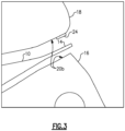
- the second tool segment 18 may include a ridge 24 in the cavity trailing edge 20b.
- the ridge 24 is an elongated elevated band that extends in the cavity 20 and aligns with the tail portion 14 such that when the fixture is closed the ridge 24 contacts the tail portion 14.
- the ridge 24 serves to concentrate pressure on the tail portion 14 during closing of the fixture 12. The concentration of pressure further urges the tail portion 14 to conform against the cavity wall of the first tool segment 16.
- the location of the ridge 24 is at a location along the trailing edge 10b that is deemed critical for high precision.
- the ridge 24 may have a height of approximately 0.001 inches (0.0254 mm) to 0.005 inches (0.127 mm).
- Such a height avoids imprinting a "step" in the trailing edge 10b of the preform 10.
- the pressure is concentrated, but without introducing an abrupt discontinuity in the smooth profile of the trailing edge 10b.
- a larger height that is above 0.005 inches (0.127 mm) up to about 0.01 inches (0.254 mm) may be used if the ridge 24 is entirely within the sacrificial tail portion 14, which will be removed in subsequent processing.
- the larger height facilitates further concentration of pressure on the tail portion 14, which may be desirable where the fibers in the trailing edge 10b are particularly stiff and resistant to conformation.
- the first tool segment 16 also includes first and second datum features 16a/16b that will be used later on to precisely position the fixture 12, and thus the preform 10, in a drilling machine.
- the first datum feature is a pin disposed in a pin hole of a boss on the segment 16
- the second datum feature 18 is a pin disposed in a pin slot of a boss at the other end of the segment 16.
- the pin/pin hole control translational degrees of freedom (in the x-axis and y-axis in the plane of the figure), and the pin/pin slot control rotational degree of freedom.
- the datum features 16a/16b will be later on used during a drilling operation to position the fixture 12 in a drilling machine for drilling the one or more cooling holes in the partially densified preform 10.
- there are other types of datum features such as but not limited to, spherical datums that may alternatively be used.
- the fixture 12 is locked in order to maintain pressure on the tail portion 14 and thus maintain the location of the tail portion 14 relative to the fixture 12.
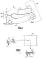
- a clamp 26 is applied near the cavity trailing edge 20b on the aft end of the fixture 12 to hold the segments 16/18 in place.
- the preform 10 is relatively stiff and there may be a substantial elastic spring-back force when the pressure is applied.
- the clamp 26 should be of robust construction and strength in order to hold the segments 16/18 together.
- the clamp 26 may be made of graphite, however, for greater strength it can alternatively be made of carbon/carbon composite or ceramic matrix composite.
- the fixture 12 and preform 10 are then inserted into a reactor 28 for deposition of one or more interface coating materials.
- the interface coating material may be, but is not limited to, boron nitride (BN), carbon, or silicon carbide (SiC).
- the resultant interface coating on the fibers of the preform 10 may include layers of two or more different interface coating materials.
- interface coatings provide a relatively weak interface between the matrix and the fibers.
- the preform 10 is partially densified in the reactor 28 to form a partially densified fiber preform 110.
- the interface coating process conducted in the reactor 28 is, but is not limited to, chemical vapor infiltration.
- the interface coating process is stopped prior to full densification of the partially densified fiber preform 110.
- the partially densified fiber preform 110 has a void volume of 40% to 50%. As will be described below, partial densification facilitates the later drilling operation.
- the drilling machine 30 may be of known construction and may include a holder (not shown), a drill head 32, and an electronic control module (not shown).
- the holder serves to secure the component fixture 12 in a known position with reference to the datum features 16a/16b so that the drill head 32 can be precisely positioned for the drilling operation.
- the holder may include one or more clamps, fasteners, clips, fixtures, adhesive, or the like that are used to mount (i.e., secure) the fixture 12.
- the drill head 32 may include a nozzle that is positioned relative to the fixture 12 in a drilling arrangement, represented at 34.
- the drilling arrangement 34 refers to the setup of the relative positioning of one or more of the datum features 16a/16b of the fixture 12 and the drill head 32 in the drilling machine 30.
- the position of the drill head 32 is precisely controlled relative to the surface of the cavity trailing edge 20b in the first tool segment 16.
- Such a positioning is desired for precision location of the cooling hole that is to be drilled relative to the suction side surface of the airfoil.
- the position of the drill head 32 may be precisely controlled relative to another surface of the cavity 20 if there are other desirable precision locations for a particular design implementation.
- the partial densification of the fiber preform 110 facilitates the drilling, as there is less material to remove in comparison to a fully densified article. Accordingly, drilling the partially densified fiber preform 110 rather than drilling a fully densified article is expected to significantly reduce process times. Additionally, although laser drilling may be used, the low density may alternatively permit machining, such as abrasive machining, mechanical drilling, ultrasonic machining, or electron beam drilling.
- the drill head 32 is set at a stand-off distance 36 from the edge of the tail portion 14.
- the electronic control module controls the drilling process, which may be conducted according to a computerized 3-dimensional model of the hole that is to be drilled.
- the hole 38 is then drilled through the tail portion 14 and trailing edge 10b until reaching the mandrel in the partially densified fiber preform 110.
- the mandrel thus serves to prevent back-strike during the drilling operation. Additional cooling holes may be drilled in a similar manner by repositioning the drill head 32 relative to the fixture 12.
- the partially densified fiber preform 110 is removed from the drilling machine 30, removed from the fixture 12, and then inserted into a reactor 40 for deposition of the matrix material.
- the resulting fully densified CMC airfoil 210 is removed from the reactor 40.
- one or more post-processing finishing processes may be conducted to complete the CMC airfoil 210.
- the deposition process may include, but is not limited to, a vapor deposition technique, such as chemical vapor infiltration.
- the matrix material may be, but is not limited to, a silicon-containing ceramic, such as a silicon carbide (SiC) or silicon nitride (Si3N4).
- the CMC airfoil 210 is a SiC/SiC ceramic matrix composite in which SiC fiber fabric is disposed within a SiC matrix.
- the presence of the holes 38 in the partially densified fiber preform 110 during subsequent densification also serves to provide passages for gas to infiltrate the partially densified fiber preform 110, resulting in higher densification. This is especially desirable at the internal surfaces of the cooling holes 38, as higher densification facilitates increased thermal conductivity, lower permeability (to hold pressure), and smoother surfaces (for lower pressure drop). Additionally, in comparison to drilling holes after full densification, the process described herein may facilitate achieving tolerances of approximately 3X smaller. Tolerance improvements may include those due to angular variation of the cooling hole, which may depend on the size of the airfoil, hole length, and distance from the point of rotation about the hinge 22. With improved positioning, the length of the trailing edge can be increased, which may increase aerodynamic efficiency.
Landscapes
- Chemical & Material Sciences (AREA)
- Engineering & Computer Science (AREA)
- Mechanical Engineering (AREA)
- Materials Engineering (AREA)
- Metallurgy (AREA)
- Chemical Kinetics & Catalysis (AREA)
- General Chemical & Material Sciences (AREA)
- Organic Chemistry (AREA)
- Inorganic Chemistry (AREA)
- General Engineering & Computer Science (AREA)
- Ceramic Engineering (AREA)
- Composite Materials (AREA)
- Turbine Rotor Nozzle Sealing (AREA)
Abstract
Description
- A gas turbine engine typically includes a fan section, a compressor section, a combustor section and a turbine section. Air entering the compressor section is compressed and delivered into the combustion section where it is mixed with fuel and ignited to generate a high-pressure and temperature exhaust gas flow. The high-pressure and temperature exhaust gas flow expands through the turbine section to drive the compressor and the fan section. The compressor section may include low and high pressure compressors, and the turbine section may also include low and high pressure turbines.
- Airfoils in the turbine section are typically formed of a superalloy and may include thermal barrier coatings to extend temperature capability and lifetime. Ceramic matrix composite ("CMC") materials are also being considered for airfoils. Among other attractive properties, CMCs have high temperature resistance. Despite this attribute, however, there are unique challenges to implementing CMCs in airfoils.
- According to a first aspect of the invention, a method for processing a CMC airfoil includes providing an airfoil fiber preform that defines a leading edge, a trailing edge, and first and second sides that join the leading edge and the trailing edge, the trailing edge having a tail portion, providing a fixture that has first and second tool segments that define a cavity there between for holding the airfoil fiber preform, the cavity having a cavity leading edge, a cavity trailing edge, and first and second cavity sides joining the cavity leading edge and the cavity trailing edge, the first and second tool segments being couplable at a hinge located near the cavity leading edge, nesting the airfoil fiber preform in the cavity, closing the fixture by rotating the first tool segment about the hinge, the closing causing the first and second tool segments to clamp on the tail portion and thereby conform the tail portion to the cavity trailing edge of the fixture, while in the fixture, partially densifying the fiber preform with an interface coating material to form a partially densified fiber preform, while in the fixture, drilling one or more cooling holes into the trailing edge of the partially densified fiber preform, and, after the drilling, removing the partially densified fiber preform from the fixture and further densifying the partially densified fiber preform with a ceramic matrix material to form a fully densified CMC airfoil.
- In an embodiment of the foregoing, the first tool segment includes first and second datum features configured to position the fixture in a drilling machine for drilling the one or more cooling holes.
- In a further embodiment of any of the foregoing, the partially densified fiber preform has a void volume of 40% to 50%.
- A further embodiment of any of the foregoing further includes, after the drilling, removing the tail portion, thereby leaving a remainder of the trailing edge with the one or more cooling holes there through.
- In a further embodiment of any of the foregoing, the second tool segment includes a ridge in the cavity trailing edge that concentrates pressure on the tail portion from the closing of the fixture.
- In a further embodiment of any of the foregoing, after the closing, the first and second tool segments are secured together by applying a clamp near the cavity trailing edge.
- In a further embodiment of any of the foregoing, the partially densifying of the fiber preform and the further densifying of the partially densified fiber preform are both conducted by vapor infiltration.
- In a further embodiment of any of the foregoing, prior to the partially densifying of the fiber preform, the fiber preform is devoid of any ceramic matrix.
- In a further embodiment of any of the foregoing, the fixture is graphite, and the partially densifying of the fiber preform and the further densifying of the partially densified fiber preform are both conducted by vapor infiltration.
- In a further embodiment of any of the foregoing, the drilling includes at least one of mechanical drilling, laser drilling, ultrasonic drilling, or electron beam drilling.
- In a further embodiment of any of the foregoing, the partially densified fiber preform has a void volume of 40% to 50%.
- According to another aspect of the invention, a fixture for forming a CMC airfoil includes first and second tool segments that define an airfoil cavity there between for receiving an airfoil fiber preform, the cavity having a cavity leading edge, a cavity trailing edge, and first and second cavity sides joining the cavity leading edge and the cavity trailing edge, the first and second tool segments being couplable at a hinge located near the cavity leading edge, and the first tool segment including first and second datum features configured to position the fixture in a drilling machine for drilling one or more cooling holes.
- In an embodiment of any of the foregoing, the first datum feature includes a pin.
- In a further embodiment of any of the foregoing, the second tool segment includes a ridge in the cavity trailing edge.
- In a further embodiment of any of the foregoing, the first and second tool segments are graphite.
- The present disclosure may include any one or more of the individual features disclosed above and/or below alone or in any combination thereof.
- The various features and advantages of the present disclosure will become apparent to those skilled in the art from the following detailed description. The drawings that accompany the detailed description can be briefly described as follows.
-
Figure 1 illustrates an airfoil fiber preform and a fixture for holding the preform during various stages of processing. -
Figure 2 illustrates the fixture in a closed position around the fiber preform. -
Figure 3 illustrates a ridge in the fixture for concentrating pressure on a tail portion of the fiber preform. -
Figure 4 illustrates a clamp on the fixture to secure the segments of the fixture together and maintain the position of the fiber preform relative to the fixture. -
Figure 5 illustrates insertion of the fixture and fiber preform into a reactor for application of interface coating materials. -
Figure 6 illustrates the fixture and partially densified fiber preform in a drilling machine for drilling a cooling hole in the article. -
Figure 7 illustrates the drilling operation, with a mandrel in the preform. -
Figure 8 illustrates the insertion of the partially densified fiber preform, after hole drilling, into a reactor for densification with a matrix material. - In this disclosure, like reference numerals designate like elements where appropriate and reference numerals with the addition of one-hundred or multiples thereof designate modified elements that are understood to incorporate the same features and benefits of the corresponding elements.
- Hot section gas turbine engine articles rely on high precision features to achieve high performance. Such features are often created via a post-fabrication machining processes. Machining these features requires precisely locating the article in space, for example in a six-point nest. The surfaces of metal-cast articles are generally sufficient for precise location. However, this process is more challenging for a CMC article that is formed from a fiber preform. For instance, fiber preforms generally have low dimensional tolerance and high surface roughness, resulting in variability when locating the article for machining. Moreover, depending on factors such as a part position in the reactor, ceramic matrix buildup can vary from part-to-part. One particular region of interest is at the trailing edge region of an airfoil, where walls are thin and precision is required for achieving operational and durability goals. In this regard, the following examples describe a method for processing a CMC airfoil to form one or more cooling holes in the trailing edge region with a high level of precision.
-
Figure 1 illustrates anairfoil fiber preform 10 and afixture 12 for holding thepreform 10 during various stages of processing. Thepreform 10 is a ceramic fiber structure that has been formed into the desired geometry of the end-use airfoil article, such as a vane or a blade. Ceramic fibers are formed of bundles of filaments and may include, but are not limited to, silicon carbide (SiC) fibers or silicon nitride (Si3N4) fibers. For instance, thepreform 10 may include multiple fiber layers or plies that are laid-up to form the desired geometry. In some instances, the fiber layers or plies are laid-up around one or more mandrels, which may remain in thepreform 10 through a portion of the processing and then be removed later on to leave one or more internal cavities in the end-use airfoil article. In general, however, theperform 10 is initially devoid of any ceramic matrix material. - The
preform 10 defines a leadingedge 10a, atrailing edge 10b, and first andsecond sides 10c/10d that join the leadingedge 10a and thetrailing edge 10b. As shown, thefirst side 10c will be the suction side of the end-use airfoil article, and thesecond side 10d will be the pressure side. Thetrailing edge 10b has atail portion 14 that extends past the location where the trailing edge is on the final article. Thetail portion 14 is sacrificial, as it is not part of the final end-use article and will be removed later in the processing. The terminology "first" and "second" as used herein is to differentiate that there are two architecturally distinct components or features. It is to be further understood that the terms "first" and "second" are interchangeable in the embodiments herein in that a first component or feature could alternatively be termed as the second component or feature, and vice versa. - The
fixture 12 is comprised of first andsecond tool segments 16/18 that define acavity 20 there between for holding thepreform 10. Thetool segments 16/18 are formed of graphite, for high temperature resistance and inertness relative to thepreform 10 and the coating that will be subsequently applied to thepreform 10. Thecavity 20 is generally complementary in geometry to the geometry of thepreform 10 and includes acavity leading edge 20a, acavity trailing edge 20b, and first andsecond cavity sides 20c/20d that join thecavity leading edge 20a and thecavity trailing edge 20b. Thetool segments 16/18 are separate pieces but are couplable at ahinge 22 located at the forward end of thefixture 12 near thecavity leading edge 20a. - With the tool segments initially 16/18 separated, the
preform 10 is nested into thefixture 12 by placing thepreform 10 into the portion of thecavity 20 in thefirst tool segment 16. The geometry of thepreform 10 is generally complementary to that of thecavity 20 such that thepreform 10 fits snugly in thecavity 20 in thefirst tool segment 16. Thecavity 20 may be very slightly oversized in order to leave a gap of up to approximately 0.005 inches between theleading edge 10a and thecavity leading edge 20a. Such a gap serves to provide clearance for the later rotation of thetool segments 16/18. - Referring to
Figure 2 , thesecond tool segment 18 is then moved into proximity of the first tool segment such that the portion of thecavity 20 in thesecond tool segment 18 is received onto, or at least into close proximity to, thepreform 10. Each of thetool segments 16/18 includes a portion of thehinge 22 such that when thesegments 16/18 are brought together the hinge portions align and permit insertion of ahinge pin 22a. Thehinge pin 22a rotatably couples thetool segments 16/18 together. - The
fixture 12 is then closed around thepreform 10 by rotating thesecond tool segment 18 about thehinge pin 22a relative to thefirst tool segment 16. The closing causes thetool segments 16/18 to clamp on thetail portion 14 of the trailingedge 10b of thepreform 10. Thehinge 22 is located opposite thetail portion 14 to provide a mechanical advantage for applying clamping force to thetail portion 14. Although thepreform 10 is relatively stiff, thetail portion 14 is thin and somewhat pliable. The clamping force urges thetail portion 14 against the cavity wall of thefirst tool segment 16. This causes thetail portion 14 to elastically deform and substantially conform to the wall of thesegment 16 in thecavity trailing edge 20b, thereby providing a precise location of the trailingedge 10b of thepreform 10 relative to thefixture 12. If desired, techniques such as X-Ray Micro Computed Tomography (xCT) or other nondestructive evaluation can be used to inspect the positioning between thetail portion 14 and the cavity wall. - Optionally, as depicted in
Figure 3 , thesecond tool segment 18 may include aridge 24 in thecavity trailing edge 20b. Theridge 24 is an elongated elevated band that extends in thecavity 20 and aligns with thetail portion 14 such that when the fixture is closed theridge 24 contacts thetail portion 14. Theridge 24 serves to concentrate pressure on thetail portion 14 during closing of thefixture 12. The concentration of pressure further urges thetail portion 14 to conform against the cavity wall of thefirst tool segment 16. For example, the location of theridge 24 is at a location along the trailingedge 10b that is deemed critical for high precision. Theridge 24 may have a height of approximately 0.001 inches (0.0254 mm) to 0.005 inches (0.127 mm). Such a height avoids imprinting a "step" in the trailingedge 10b of thepreform 10. Thus, the pressure is concentrated, but without introducing an abrupt discontinuity in the smooth profile of the trailingedge 10b. Alternatively, a larger height that is above 0.005 inches (0.127 mm) up to about 0.01 inches (0.254 mm) may be used if theridge 24 is entirely within thesacrificial tail portion 14, which will be removed in subsequent processing. The larger height facilitates further concentration of pressure on thetail portion 14, which may be desirable where the fibers in the trailingedge 10b are particularly stiff and resistant to conformation. - The
first tool segment 16 also includes first and second datum features 16a/16b that will be used later on to precisely position thefixture 12, and thus thepreform 10, in a drilling machine. For example, the first datum feature is a pin disposed in a pin hole of a boss on thesegment 16, and thesecond datum feature 18 is a pin disposed in a pin slot of a boss at the other end of thesegment 16. The pin/pin hole control translational degrees of freedom (in the x-axis and y-axis in the plane of the figure), and the pin/pin slot control rotational degree of freedom. The datum features 16a/16b will be later on used during a drilling operation to position thefixture 12 in a drilling machine for drilling the one or more cooling holes in the partially densifiedpreform 10. As will be appreciated, there are other types of datum features, such as but not limited to, spherical datums that may alternatively be used. - After the closing of the
fixture 12, thefixture 12 is locked in order to maintain pressure on thetail portion 14 and thus maintain the location of thetail portion 14 relative to thefixture 12. For example, as shown inFigure 4 , aclamp 26 is applied near thecavity trailing edge 20b on the aft end of thefixture 12 to hold thesegments 16/18 in place. Thepreform 10 is relatively stiff and there may be a substantial elastic spring-back force when the pressure is applied. In this regard, theclamp 26 should be of robust construction and strength in order to hold thesegments 16/18 together. In some examples, theclamp 26 may be made of graphite, however, for greater strength it can alternatively be made of carbon/carbon composite or ceramic matrix composite. - As shown in
Figure 5 , once mounted in thefixture 12, thefixture 12 and preform 10 are then inserted into areactor 28 for deposition of one or more interface coating materials. The interface coating material may be, but is not limited to, boron nitride (BN), carbon, or silicon carbide (SiC). For example, the resultant interface coating on the fibers of thepreform 10 may include layers of two or more different interface coating materials. As is known, interface coatings provide a relatively weak interface between the matrix and the fibers. Thepreform 10 is partially densified in thereactor 28 to form a partially densifiedfiber preform 110. As an example, the interface coating process conducted in thereactor 28 is, but is not limited to, chemical vapor infiltration. The interface coating process is stopped prior to full densification of the partially densifiedfiber preform 110. For instance, the partially densifiedfiber preform 110 has a void volume of 40% to 50%. As will be described below, partial densification facilitates the later drilling operation. - As shown in
Figure 6 , while still in thefixture 12 the partially densifiedfiber preform 110 is removed from thereactor 28 and then mounted in adrilling machine 30. Thedrilling machine 30 may be of known construction and may include a holder (not shown), adrill head 32, and an electronic control module (not shown). The holder serves to secure thecomponent fixture 12 in a known position with reference to the datum features 16a/16b so that thedrill head 32 can be precisely positioned for the drilling operation. The holder may include one or more clamps, fasteners, clips, fixtures, adhesive, or the like that are used to mount (i.e., secure) thefixture 12. In the case of laser drilling (e.g., water-guided laser drilling), thedrill head 32 may include a nozzle that is positioned relative to thefixture 12 in a drilling arrangement, represented at 34. Thedrilling arrangement 34 refers to the setup of the relative positioning of one or more of the datum features 16a/16b of thefixture 12 and thedrill head 32 in thedrilling machine 30. In this manner, the position of thedrill head 32 is precisely controlled relative to the surface of thecavity trailing edge 20b in thefirst tool segment 16. Such a positioning is desired for precision location of the cooling hole that is to be drilled relative to the suction side surface of the airfoil. As will be appreciated, the position of thedrill head 32 may be precisely controlled relative to another surface of thecavity 20 if there are other desirable precision locations for a particular design implementation. - The partial densification of the
fiber preform 110 facilitates the drilling, as there is less material to remove in comparison to a fully densified article. Accordingly, drilling the partially densifiedfiber preform 110 rather than drilling a fully densified article is expected to significantly reduce process times. Additionally, although laser drilling may be used, the low density may alternatively permit machining, such as abrasive machining, mechanical drilling, ultrasonic machining, or electron beam drilling. - As shown in
Figure 7 , thedrill head 32 is set at a stand-off distance 36 from the edge of thetail portion 14. In the drilling operation, the electronic control module controls the drilling process, which may be conducted according to a computerized 3-dimensional model of the hole that is to be drilled. Thehole 38 is then drilled through thetail portion 14 and trailingedge 10b until reaching the mandrel in the partially densifiedfiber preform 110. The mandrel thus serves to prevent back-strike during the drilling operation. Additional cooling holes may be drilled in a similar manner by repositioning thedrill head 32 relative to thefixture 12. - Referring to
Figure 8 , after the drilling, the partially densifiedfiber preform 110 is removed from thedrilling machine 30, removed from thefixture 12, and then inserted into areactor 40 for deposition of the matrix material. Upon full densification (e.g., 15% void volume or less), the resulting fully densified CMC airfoil 210 is removed from thereactor 40. If necessary, one or more post-processing finishing processes may be conducted to complete the CMC airfoil 210. The deposition process may include, but is not limited to, a vapor deposition technique, such as chemical vapor infiltration. The matrix material may be, but is not limited to, a silicon-containing ceramic, such as a silicon carbide (SiC) or silicon nitride (Si3N4). For instance, the CMC airfoil 210 is a SiC/SiC ceramic matrix composite in which SiC fiber fabric is disposed within a SiC matrix. - The presence of the
holes 38 in the partially densifiedfiber preform 110 during subsequent densification also serves to provide passages for gas to infiltrate the partially densifiedfiber preform 110, resulting in higher densification. This is especially desirable at the internal surfaces of the cooling holes 38, as higher densification facilitates increased thermal conductivity, lower permeability (to hold pressure), and smoother surfaces (for lower pressure drop). Additionally, in comparison to drilling holes after full densification, the process described herein may facilitate achieving tolerances of approximately 3X smaller. Tolerance improvements may include those due to angular variation of the cooling hole, which may depend on the size of the airfoil, hole length, and distance from the point of rotation about thehinge 22. With improved positioning, the length of the trailing edge can be increased, which may increase aerodynamic efficiency. - Although a combination of features is shown in the illustrated examples, not all of them need to be combined to realize the benefits of various embodiments of this disclosure. In other words, a system designed according to an embodiment of this disclosure will not necessarily include all of the features shown in any one of the Figures or all of the portions schematically shown in the Figures. Moreover, selected features of one example embodiment may be combined with selected features of other example embodiments.
- The preceding description is exemplary rather than limiting in nature. Variations and modifications to the disclosed examples may become apparent to those skilled in the art that do not necessarily depart from this disclosure. The scope of legal protection given to this disclosure can only be determined by studying the following claims.
Claims (14)
- A method for processing a CMC airfoil (210), the method comprising:providing an airfoil fiber preform (10) that defines a leading edge (10a), a trailing edge (10b), and first and second sides (10c/10d) that join the leading edge (10a) and the trailing edge (10b), the trailing edge (10b) having a tail portion (14);providing a fixture (12) that has first and second tool segments (16/18) that define a cavity (20) therebetween for holding the airfoil fiber preform (10), the cavity (20) having a cavity leading edge (20a), a cavity trailing edge (20b), and first and second cavity sides (20c/20d) joining the cavity leading edge (20a) and the cavity trailing edge (20b), the first and second tool segments (16/18) being couplable at a hinge (22) located near the cavity leading edge (20a);nesting the airfoil fiber preform (10) in the cavity (20);closing the fixture (12) by rotating the first tool segment (16) about the hinge (22), the closing causing the first and second tool segments (16/18) to clamp on the tail portion (14) and thereby conform the tail portion (14) to the cavity trailing edge (20b) of the fixture (12);while in the fixture (12), partially densifying the fiber preform (10) with an interface coating material to form a partially densified fiber preform (110);while in the fixture (12), drilling one or more cooling holes (38) into the trailing edge (10b) of the partially densified fiber preform (110); andafter the drilling, removing the partially densified fiber preform (110) from the fixture (12) and further densifying the partially densified fiber preform (110) with a ceramic matrix material to form a fully densified CMC airfoil (210).
- The method as recited in claim 1, wherein the first tool segment (16) includes first and second datum features (16a/16b) configured to position the fixture (12) in a drilling machine (30) for drilling the one or more cooling holes (38).
- The method as recited in claim 1 or 2, wherein the partially densified fiber preform (110) has a void volume of 40% to 50%.
- The method as recited in any preceding claim, further comprising, after the drilling, removing the tail portion (14), thereby leaving a remainder of the trailing edge (10b) with the one or more cooling holes (38) therethrough.
- The method as recited in any preceding claim, wherein the second tool segment (18) includes a ridge (24) in the cavity trailing edge (20b) that concentrates pressure on the tail portion (14) from the closing of the fixture (12).
- The method as recited in any preceding claim, wherein, after the closing, the first and second tool segments (16/18) are secured together by applying a clamp (26) near the cavity trailing edge (20b).
- The method as recited in any preceding claim, wherein the partially densifying of the fiber preform (110) and the further densifying of the partially densified fiber preform (110) are both conducted by vapor infiltration.
- The method as recited in any preceding claim, wherein the fixture (12) is graphite.
- The method as recited in any preceding claim, wherein prior to the partially densifying of the fiber preform (110), the fiber preform (110) is devoid of any ceramic matrix.
- The method as recited in any preceding claim, wherein the drilling includes mechanical drilling, laser drilling, ultrasonic drilling, and/or electron beam drilling.
- A fixture (12) for forming a CMC airfoil (210), comprising first and second tool segments (16/18) that define an airfoil cavity (20) therebetween for receiving an airfoil fiber preform (10), the cavity (20) having a cavity leading edge (20a), a cavity trailing edge (20b), and first and second cavity sides (20c/20d) joining the cavity leading edge (20a) and the cavity trailing edge (20b), the first and second tool segments (16/18) being couplable at a hinge (22) located near the cavity leading edge (20a), the first tool segment (16) including first and second datum features (16a/16b) configured to position the fixture (12) in a drilling machine (30) for drilling one or more cooling holes (38).
- The fixture (12) as recited in claim 11, wherein the first datum feature (16a) includes a pin.
- The fixture (12) as recited in claim 11 or 12, wherein the second tool segment (18) includes a ridge (24) in the cavity trailing edge (20b).
- The fixture (12) as recited in any of claims 11 to 13, wherein the first and second tool segments (16/18) are graphite.
Applications Claiming Priority (1)
| Application Number | Priority Date | Filing Date | Title |
|---|---|---|---|
| US17/990,974 US11866820B1 (en) | 2022-11-21 | 2022-11-21 | Method of processing a CMC airfoil |
Publications (2)
| Publication Number | Publication Date |
|---|---|
| EP4371700A1 true EP4371700A1 (en) | 2024-05-22 |
| EP4371700B1 EP4371700B1 (en) | 2026-04-08 |
Family
ID=88921057
Family Applications (1)
| Application Number | Title | Priority Date | Filing Date |
|---|---|---|---|
| EP23211307.6A Active EP4371700B1 (en) | 2022-11-21 | 2023-11-21 | Method of processing a cmc airfoil and used fixture |
Country Status (2)
| Country | Link |
|---|---|
| US (2) | US11866820B1 (en) |
| EP (1) | EP4371700B1 (en) |
Families Citing this family (1)
| Publication number | Priority date | Publication date | Assignee | Title |
|---|---|---|---|---|
| US20250250914A1 (en) * | 2024-02-01 | 2025-08-07 | Chromalloy Gas Turbine Llc | Tooling and method for masking a turbine component such as a blade or vane |
Citations (3)
| Publication number | Priority date | Publication date | Assignee | Title |
|---|---|---|---|---|
| US20060292005A1 (en) * | 2005-06-23 | 2006-12-28 | United Technologies Corporation | Method for forming turbine blade with angled internal ribs |
| US11104032B2 (en) * | 2018-04-19 | 2021-08-31 | General Electric Company | Tooling assembly having cam closing feature |
| US11286792B2 (en) * | 2019-07-30 | 2022-03-29 | Rolls-Royce Plc | Ceramic matrix composite vane with cooling holes and methods of making the same |
Family Cites Families (2)
| Publication number | Priority date | Publication date | Assignee | Title |
|---|---|---|---|---|
| JP6763157B2 (en) | 2016-03-11 | 2020-09-30 | 株式会社Ihi | Turbine nozzle |
| US10906842B2 (en) | 2018-10-18 | 2021-02-02 | Rolls-Royce High Temperature Composites Inc. | Method of processing a ceramic matrix composite (CMC) component |
-
2022
- 2022-11-21 US US17/990,974 patent/US11866820B1/en active Active
-
2023
- 2023-09-14 US US18/466,924 patent/US12037680B2/en active Active
- 2023-11-21 EP EP23211307.6A patent/EP4371700B1/en active Active
Patent Citations (3)
| Publication number | Priority date | Publication date | Assignee | Title |
|---|---|---|---|---|
| US20060292005A1 (en) * | 2005-06-23 | 2006-12-28 | United Technologies Corporation | Method for forming turbine blade with angled internal ribs |
| US11104032B2 (en) * | 2018-04-19 | 2021-08-31 | General Electric Company | Tooling assembly having cam closing feature |
| US11286792B2 (en) * | 2019-07-30 | 2022-03-29 | Rolls-Royce Plc | Ceramic matrix composite vane with cooling holes and methods of making the same |
Also Published As
| Publication number | Publication date |
|---|---|
| EP4371700B1 (en) | 2026-04-08 |
| US12037680B2 (en) | 2024-07-16 |
| US11866820B1 (en) | 2024-01-09 |
| US20240167152A1 (en) | 2024-05-23 |
Similar Documents
| Publication | Publication Date | Title |
|---|---|---|
| EP3153484B1 (en) | Ceramic matrix composite component and process of producing a ceramic matrix composite component | |
| EP2366678B1 (en) | High tolerance controlled surface for ceramic matrix composite component | |
| US9050769B2 (en) | Pre-form ceramic matrix composite cavity and method of forming and method of forming a ceramic matrix composite component | |
| CN110872954A (en) | CMC component including directionally controllable CMC insert and method of making | |
| CA3102096C (en) | Ceramic matrix composite component and method of producing a ceramic matrix composite component | |
| US7247212B2 (en) | Orthogonal weaving for complex shape preforms | |
| US20170122113A1 (en) | Ceramic matrix composite component and process of producing a ceramic matrix composite component | |
| US10632650B2 (en) | Methods and assemblies for forming features in composite components | |
| US12157708B2 (en) | Method for creating cooling holes in a CMC laminate | |
| US20140199174A1 (en) | Method of forming a ceramic matrix composite component, a ceramic matrix composite component and a tip member | |
| EP4371700B1 (en) | Method of processing a cmc airfoil and used fixture | |
| EP3556510A1 (en) | Tooling assembly having cam closing feature | |
| CN108691580B (en) | Method and assembly for forming features in composite components | |
| CN108749021B (en) | Method and assembly for forming features in composite components | |
| US12480412B2 (en) | Insertion of ceramic members for gas path endwall contouring | |
| US20250263345A1 (en) | Insertion of ceramic members for gas path endwall contouring |
Legal Events
| Date | Code | Title | Description |
|---|---|---|---|
| PUAI | Public reference made under article 153(3) epc to a published international application that has entered the european phase |
Free format text: ORIGINAL CODE: 0009012 |
|
| STAA | Information on the status of an ep patent application or granted ep patent |
Free format text: STATUS: THE APPLICATION HAS BEEN PUBLISHED |
|
| AK | Designated contracting states |
Kind code of ref document: A1 Designated state(s): AL AT BE BG CH CY CZ DE DK EE ES FI FR GB GR HR HU IE IS IT LI LT LU LV MC ME MK MT NL NO PL PT RO RS SE SI SK SM TR |
|
| STAA | Information on the status of an ep patent application or granted ep patent |
Free format text: STATUS: REQUEST FOR EXAMINATION WAS MADE |
|
| 17P | Request for examination filed |
Effective date: 20241122 |
|
| RBV | Designated contracting states (corrected) |
Designated state(s): AL AT BE BG CH CY CZ DE DK EE ES FI FR GB GR HR HU IE IS IT LI LT LU LV MC ME MK MT NL NO PL PT RO RS SE SI SK SM TR |
|
| GRAP | Despatch of communication of intention to grant a patent |
Free format text: ORIGINAL CODE: EPIDOSNIGR1 |
|
| STAA | Information on the status of an ep patent application or granted ep patent |
Free format text: STATUS: GRANT OF PATENT IS INTENDED |
|
| INTG | Intention to grant announced |
Effective date: 20251031 |
|
| GRAS | Grant fee paid |
Free format text: ORIGINAL CODE: EPIDOSNIGR3 |
|
| GRAA | (expected) grant |
Free format text: ORIGINAL CODE: 0009210 |
|
| STAA | Information on the status of an ep patent application or granted ep patent |
Free format text: STATUS: THE PATENT HAS BEEN GRANTED |
|
| AK | Designated contracting states |
Kind code of ref document: B1 Designated state(s): AL AT BE BG CH CY CZ DE DK EE ES FI FR GB GR HR HU IE IS IT LI LT LU LV MC ME MK MT NL NO PL PT RO RS SE SI SK SM TR |
|
| REG | Reference to a national code |
Ref country code: CH Ref legal event code: F10 Free format text: ST27 STATUS EVENT CODE: U-0-0-F10-F00 (AS PROVIDED BY THE NATIONAL OFFICE) Effective date: 20260408 Ref country code: GB Ref legal event code: FG4D |
|
| REG | Reference to a national code |
Ref country code: DE Ref legal event code: R096 Ref document number: 602023014830 Country of ref document: DE |