EP4371621A1 - Firewater monitor brake system and method - Google Patents
Firewater monitor brake system and method Download PDFInfo
- Publication number
- EP4371621A1 EP4371621A1 EP23205291.0A EP23205291A EP4371621A1 EP 4371621 A1 EP4371621 A1 EP 4371621A1 EP 23205291 A EP23205291 A EP 23205291A EP 4371621 A1 EP4371621 A1 EP 4371621A1
- Authority
- EP
- European Patent Office
- Prior art keywords
- brake
- horizontal
- vertical
- firewater
- monitor
- Prior art date
- Legal status (The legal status is an assumption and is not a legal conclusion. Google has not performed a legal analysis and makes no representation as to the accuracy of the status listed.)
- Granted
Links
Images







Classifications
-
- A—HUMAN NECESSITIES
- A62—LIFE-SAVING; FIRE-FIGHTING
- A62C—FIRE-FIGHTING
- A62C31/00—Delivery of fire-extinguishing material
- A62C31/02—Nozzles specially adapted for fire-extinguishing
- A62C31/24—Nozzles specially adapted for fire-extinguishing attached to ladders, poles, towers, or other structures with or without rotary heads
-
- F—MECHANICAL ENGINEERING; LIGHTING; HEATING; WEAPONS; BLASTING
- F16—ENGINEERING ELEMENTS AND UNITS; GENERAL MEASURES FOR PRODUCING AND MAINTAINING EFFECTIVE FUNCTIONING OF MACHINES OR INSTALLATIONS; THERMAL INSULATION IN GENERAL
- F16D—COUPLINGS FOR TRANSMITTING ROTATION; CLUTCHES; BRAKES
- F16D65/00—Parts or details
- F16D65/14—Actuating mechanisms for brakes; Means for initiating operation at a predetermined position
- F16D65/16—Actuating mechanisms for brakes; Means for initiating operation at a predetermined position arranged in or on the brake
- F16D65/18—Actuating mechanisms for brakes; Means for initiating operation at a predetermined position arranged in or on the brake adapted for drawing members together, e.g. for disc brakes
- F16D65/183—Actuating mechanisms for brakes; Means for initiating operation at a predetermined position arranged in or on the brake adapted for drawing members together, e.g. for disc brakes with force-transmitting members arranged side by side acting on a spot type force-applying member
-
- A—HUMAN NECESSITIES
- A62—LIFE-SAVING; FIRE-FIGHTING
- A62C—FIRE-FIGHTING
- A62C37/00—Control of fire-fighting equipment
- A62C37/50—Testing or indicating devices for determining the state of readiness of the equipment
-
- B—PERFORMING OPERATIONS; TRANSPORTING
- B60—VEHICLES IN GENERAL
- B60T—VEHICLE BRAKE CONTROL SYSTEMS OR PARTS THEREOF; BRAKE CONTROL SYSTEMS OR PARTS THEREOF, IN GENERAL; ARRANGEMENT OF BRAKING ELEMENTS ON VEHICLES IN GENERAL; PORTABLE DEVICES FOR PREVENTING UNWANTED MOVEMENT OF VEHICLES; VEHICLE MODIFICATIONS TO FACILITATE COOLING OF BRAKES
- B60T1/00—Arrangements of braking elements, i.e. of those parts where braking effect occurs specially for vehicles
-
- F—MECHANICAL ENGINEERING; LIGHTING; HEATING; WEAPONS; BLASTING
- F16—ENGINEERING ELEMENTS AND UNITS; GENERAL MEASURES FOR PRODUCING AND MAINTAINING EFFECTIVE FUNCTIONING OF MACHINES OR INSTALLATIONS; THERMAL INSULATION IN GENERAL
- F16L—PIPES; JOINTS OR FITTINGS FOR PIPES; SUPPORTS FOR PIPES, CABLES OR PROTECTIVE TUBING; MEANS FOR THERMAL INSULATION IN GENERAL
- F16L27/00—Adjustable joints; Joints allowing movement
- F16L27/08—Adjustable joints; Joints allowing movement allowing adjustment or movement only about the axis of one pipe
-
- A—HUMAN NECESSITIES
- A62—LIFE-SAVING; FIRE-FIGHTING
- A62C—FIRE-FIGHTING
- A62C31/00—Delivery of fire-extinguishing material
- A62C31/28—Accessories for delivery devices, e.g. supports
-
- B—PERFORMING OPERATIONS; TRANSPORTING
- B05—SPRAYING OR ATOMISING IN GENERAL; APPLYING FLUENT MATERIALS TO SURFACES, IN GENERAL
- B05B—SPRAYING APPARATUS; ATOMISING APPARATUS; NOZZLES
- B05B15/00—Details of spraying plant or spraying apparatus not otherwise provided for; Accessories
- B05B15/60—Arrangements for mounting, supporting or holding spraying apparatus
- B05B15/65—Mounting arrangements for fluid connection of the spraying apparatus or its outlets to flow conduits
- B05B15/652—Mounting arrangements for fluid connection of the spraying apparatus or its outlets to flow conduits whereby the jet can be oriented
-
- B—PERFORMING OPERATIONS; TRANSPORTING
- B05—SPRAYING OR ATOMISING IN GENERAL; APPLYING FLUENT MATERIALS TO SURFACES, IN GENERAL
- B05B—SPRAYING APPARATUS; ATOMISING APPARATUS; NOZZLES
- B05B15/00—Details of spraying plant or spraying apparatus not otherwise provided for; Accessories
- B05B15/60—Arrangements for mounting, supporting or holding spraying apparatus
- B05B15/68—Arrangements for adjusting the position of spray heads
-
- B—PERFORMING OPERATIONS; TRANSPORTING
- B60—VEHICLES IN GENERAL
- B60T—VEHICLE BRAKE CONTROL SYSTEMS OR PARTS THEREOF; BRAKE CONTROL SYSTEMS OR PARTS THEREOF, IN GENERAL; ARRANGEMENT OF BRAKING ELEMENTS ON VEHICLES IN GENERAL; PORTABLE DEVICES FOR PREVENTING UNWANTED MOVEMENT OF VEHICLES; VEHICLE MODIFICATIONS TO FACILITATE COOLING OF BRAKES
- B60T13/00—Transmitting braking action from initiating means to ultimate brake actuator with power assistance or drive; Brake systems incorporating such transmitting means, e.g. air-pressure brake systems
- B60T13/74—Transmitting braking action from initiating means to ultimate brake actuator with power assistance or drive; Brake systems incorporating such transmitting means, e.g. air-pressure brake systems with electrical assistance or drive
- B60T13/745—Transmitting braking action from initiating means to ultimate brake actuator with power assistance or drive; Brake systems incorporating such transmitting means, e.g. air-pressure brake systems with electrical assistance or drive acting on a hydraulic system, e.g. a master cylinder
-
- F—MECHANICAL ENGINEERING; LIGHTING; HEATING; WEAPONS; BLASTING
- F16—ENGINEERING ELEMENTS AND UNITS; GENERAL MEASURES FOR PRODUCING AND MAINTAINING EFFECTIVE FUNCTIONING OF MACHINES OR INSTALLATIONS; THERMAL INSULATION IN GENERAL
- F16D—COUPLINGS FOR TRANSMITTING ROTATION; CLUTCHES; BRAKES
- F16D2121/00—Type of actuator operation force
- F16D2121/02—Fluid pressure
- F16D2121/04—Fluid pressure acting on a piston-type actuator, e.g. for liquid pressure
- F16D2121/06—Fluid pressure acting on a piston-type actuator, e.g. for liquid pressure for releasing a normally applied brake
-
- F—MECHANICAL ENGINEERING; LIGHTING; HEATING; WEAPONS; BLASTING
- F16—ENGINEERING ELEMENTS AND UNITS; GENERAL MEASURES FOR PRODUCING AND MAINTAINING EFFECTIVE FUNCTIONING OF MACHINES OR INSTALLATIONS; THERMAL INSULATION IN GENERAL
- F16D—COUPLINGS FOR TRANSMITTING ROTATION; CLUTCHES; BRAKES
- F16D2121/00—Type of actuator operation force
- F16D2121/14—Mechanical
Definitions
- the present disclosure relates generally to fire water monitors. More specifically, the present disclosure relates a firewater monitor brake system and method.
- Firewater monitors range in size - flowing from hundreds to tens of thousands of gallons of water flow per minute. Firewater monitors offer motive water flow to a nozzle affixed to the monitor tip for delivering water and/or extinguishing agents as a mitigating factor onto an airborne hazard and/or fire.
- Monitor designs include both manually-operated and motor-actuated configurations.
- Motor-actuated monitors are controlled by protected electric, hydraulic or pneumaticactuated gear mechanisms that produce vertical and horizontal travel, determining positon while also limiting free movement of the monitor along its course of travel.
- Manually-operated monitors may also include gear mechanisms for controlling monitor travel, where gears are manipulated manually by hand by an operator. Pace of movement along both horizontal and vertical axes for gear-operated monitors is limited by the mechanical ratio of the controlling gears.
- manually-operated monitors may also include a tiller bar design-a single point of contact with the monitor either by one controller bar or lever, or by a dual, handle-bar style controller used by an operator to control monitor movement more freely along both vertical and horizontal axes.
- This monitor design allows for more rapid, free movement along both axes and commonly relies on manual locking mechanisms to fix and to secure the monitor positon - one lock for vertical travel and a second lock for horizontal travel.
- This tiller-bar styled monitor offers the benefit of rapid monitor movement by the operator. In fire response, this rapid response capability is preferred in a manned response effort to assure prompt critical life safety controls against what is commonly an ever changing threat.
- the firewater monitor brake system and method of the present invention offers an automated, fail-safe safety mechanism that locks the position of a manually-operated monitor in the event of loss of control by the operator.
- the firewater monitor brake system may comprise one or more brake system, each activated and deactivated by one or more lever system, which opens or closes each brake system around a "locking disc” collar.
- One locking disc collar may be affixed externally around a circumference (i.e., circular cross section) or an outer surface (e.g., elliptical cross section) of a horizontal waterway of a firewater monitor system; and another locking disc collar may be affixed externally around a circumference (i.e., circular cross section) or an outer surface (e.g., elliptical cross section) of a vertical waterway of the firewater monitor system.
- one locking disc collar may be affixed internally around an inner circumference (i.e., circular cross section) or an inner surface (e.g., elliptical cross section) of a horizontal waterway of a firewater monitor system; and another locking disc collar may be affixed internally around an inner circumference (i.e., circular cross section) or an inner surface (e.g., elliptical cross section) of a vertical waterway of the firewater monitor system.
- Each brake system has an open and a closed position.
- the closed or “actuated” position of the brake system is its “resting state,” which clamps the locking disc collar with sufficient energy as to prohibit rotational movement of the monitor waterway around its particular axis.
- the brake system is "deactivated” to its open position by depressing the lever system, the brake system releases the locking disc collar allowing free movement of the monitor waterway around is particular axis.
- intentional or accidental release of one or more lever system actuates the brake system, thereby, clamping down on one or more locking discs collars to stop / lock the firewater monitor system's position and prevent further travel in either the horizontal and/or vertical direction.
- Operation of the firewater monitor brake system may be integrated into the firewater monitor system's handle-bar styled controller as an ergonomic accessory lever system that will simultaneously activate and deactivate one or more brake systems. While gripping the firewater monitor system's handle bar for normal operation, this lever system may be depressed naturally, thereby, deactivating one or more brake system to its open position, which allows controlled monitor movement by the operator. When one or more lever system is released - either intentionally or accidently - the one or more brake system activates to a closed position immediately stopping / locking the firewater monitor system's position and preventing further travel in either the horizontal and/or vertical direction.
- the vertical brake system is selected from the group consisting of a plate-on-plate brake system, a meshed-teeth brake system, a retracting, locking pin brake system and combinations thereof.
- the horizontal brake system is selected from the group consisting of a plate-on-plate brake system, a meshed-teeth brake system, a retracting, locking pin brake system and combinations thereof.
- one or more of the vertical brake system and the horizontal brake system is a caliper brake system.
- one or more of the vertical brake system and the horizontal brake system is a disc brake system.
- one or more of the vertical brake system and the horizontal brake system is a meshed-teeth braking system.
- one or more of the vertical brake system and the horizontal brake system is a retracting, locking pin brake system.
- one or more of the vertical brake system and the horizontal brake system is capable of an activated, closed position, clamping the vertical locking disc collar and/or the horizontal locking collar with sufficient energy to prevent rotational movement of a horizontal waterway and/or a vertical waterway of the firewater monitor system.
- one or more of the vertical brake system and the horizontal brake system is capable of a deactivated, open position, releasing the vertical locking disc collar and/or the horizontal locking collar to allow rotational movement of a horizontal waterway and/or a vertical waterway of the firewater monitor system.
- the master cylinder is a hydraulic master cylinder or radial master cylinder. In an embodiment, the master cylinder is a hydraulic master cylinder. In an embodiment, the master cylinder is a radial master cylinder.
- the lever system may be hand or foot operated. In an embodiment, the lever system is hand operated. In an embodiment, the lever system is foot operated.
- the lever system is selected of the group consisting of a caliper-style lever system, a side-to-side handle-style lever system, a top-to-bottom-style lever system and combinations thereof.
- the lever system is a caliper-style lever system.
- the lever system is a side-to-side handle-style (e.g., lawn mower lever) lever system.
- the lever system is a top-to-bottom handle-style lever system.
- the lever system is selected from the group consisting of a button-style (e.g., anchor windlass) lever system, a pedal-style (e.g., sewing machine pedal) lever system and combinations thereof.
- a button-style e.g., anchor windlass
- a pedal-style e.g., sewing machine pedal
- the actuation system is selected from the group of cable-linkage systems, hydraulic systems, pneumatic systems and combinations thereof.
- the actuation system is a cable-linkage system.
- the actuation system is a hydraulic system.
- the actuation system is a pneumatic system.
- the method further comprises: releasing one or more lever to activate the vertical brake and/or the horizontal brake.
- the method comprises: depressing a vertical lever to deactivate the vertical brake. In an embodiment, the method further comprises: releasing the vertical lever to activate the vertical brake.
- the method comprises depressing a horizontal lever to deactivate the horizontal brake. In an embodiment, the method further comprises: releasing a horizontal lever to activate the horizontal brake.
- a firewater monitor brake system comprising:
- Clause 7 The system of clause 1, wherein one or more of the vertical brake system and the horizontal brake system is a retracting, locking pin brake system.
- Clause 8 The system of clause 1, wherein one or more of the vertical brake system and the horizontal brake system is capable of an activated, closed position, clamping the vertical locking disc collar and/or the horizontal locking collar with sufficient energy to prevent rotational movement of a horizontal waterway and/or a vertical waterway of the firewater monitor system.
- lever system is selected of the group consisting of a caliper-style lever system, a side-to-side handle-style lever system, a top-to-bottom-style lever system and combinations thereof.
- lever system is selected from the group consisting of a button-style lever system, a pedal-style lever system and combinations thereof.
- Clause 24 The method of clause 23 further comprising: c) releasing one or more lever to activate the vertical brake and/or the horizontal brake.
- step b) comprises depressing a vertical lever to deactivate the vertical brake.
- step b) comprises depressing a horizontal lever to deactivate the horizontal brake.
- step c) comprises releasing the vertical lever to activate the vertical brake.
- step c) comprises releasing a horizontal lever to activate the horizontal brake.
- a firewater monitor brake system comprising:
- Clause 30 The system of clause 29, wherein the horizontal brake is a plate-on-plate brake system.
- Clause 31 The system of clause 29, wherein the horizontal brake is a caliper brake system.
- Clause 32 The system of clause 29, wherein the horizontal brake is a disc brake system.
- Clause 33 The system of clause 29, further comprising a horizontal locking disc collar coupled to the horizontal swivel, wherein the horizontal brake is capable of an activated, closed position, clamping the horizontal locking disc collar with sufficient energy to prevent rotational movement of the horizontal waterway.
- Clause 34 The system of clause 29, further comprising a horizontal locking disc collar coupled to the horizontal swivel, wherein the horizontal brake is capable of a deactivated, open position, releasing the horizontal locking disc collar to allow rotational movement of the horizontal waterway.
- Clause 36 The system of clause 29, further comprising a master cylinder adapted to be affixed to the tiller bar, wherein the master cylinder is connected to and/or coupled to the horizontal brake lever and wherein the master cylinder is connected to and/or coupled to the horizontal brake via the horizontal actuation system.
- Clause 39 The system of clause 37, further comprising a vertical locking disc collar coupled to the vertical swivel, wherein the vertical brake is capable of an activated, closed position, clamping the vertical locking disc collar with sufficient energy to prevent rotational movement of the vertical waterway.
- Clause 40 The system of clause 37, further comprising a vertical locking disc collar coupled to the vertical swivel, wherein the vertical brake system is capable of a deactivated, open position, releasing the vertical locking disc collar to allow rotational movement of the vertical waterway.
- Clause 42 The system of clause 37, further comprising a master cylinder adapted to be affixed to the tiller bar, wherein the master cylinder is connected to and/or coupled to the vertical brake lever and wherein the master cylinder is connected to and/or coupled to the vertical brake via the vertical actuation system.
- a firewater monitor brake system comprising:
- Clause 48 The system of clause 44, wherein the horizontal brake system is a caliper brake system.
- Clause 54 The system of clause 45, wherein one or more of the horizontal brake system and the vertical brake system is capable of an activated, closed position, clamping a horizontal locking disc collar and/or a vertical locking disc collar with sufficient energy to prevent rotational movement of a horizontal waterway and/or a vertical waterway of the firewater monitor system.
- Clause 55 The system of clause 45, wherein one or more of the horizontal brake system and the vertical brake system is capable of a deactivated, open position, releasing a horizontal locking disc collar and/or a vertical locking disc collar to allow rotational movement of a horizontal waterway and/or a vertical waterway of the firewater monitor system.
- Clause 60 The system of clause 44, wherein the horizontal actuation system is selected from the group consisting of a cable-linkage system, a hydraulic system, a pneumatic system, and combinations thereof.
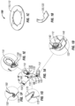
- FIG. 1A illustrates a rear, upper perspective view of a firewater monitor brake system 100 according to an embodiment of the present invention
- FIG. 1B illustrates a detail view of an exemplary brake mount 120, 122 for the firewater monitor brake system 100 of FIG. 1A
- FIG. 1C illustrates a detail view of an exemplary locking disc collar 110, 112 for the firewater monitor brake system 100 of FIGS. 1A-1B
- FIG. 1D illustrates a detail view of an exemplary horizontal brake system 140, exemplary horizontal brake mount 122 and an exemplary horizontal locking disc collar 112 for the firewater monitor brake system 100 of FIGS. 1A-1C
- FIG. 1A illustrates a rear, upper perspective view of a firewater monitor brake system 100 according to an embodiment of the present invention
- FIG. 1B illustrates a detail view of an exemplary brake mount 120, 122 for the firewater monitor brake system 100 of FIG. 1A
- FIG. 1C illustrates a detail view of an exemplary locking disc collar 110, 112 for the firewater monitor brake
- FIG. 1E illustrates a detail view of an exemplary vertical brake system 130, an exemplary vertical brake mount 120 and an exemplary vertical locking disc collar 110 for the firewater monitor brake system 100 of FIGS. 1A-1D
- FIG. 1F illustrates a detail view of an exemplary lever system 160 for the firewater monitor brake system 100 of FIGS. 1A-1E
- FIG. 1G illustrates detail view of an exemplary actuation system 170 for the firewater monitor brake system 100 of FIG. 1A
- FIG. 1H illustrates a rear, upper perspective view of the firewater monitor brake system 100 of FIGS. 1A-1F installed on an exemplary firewater monitor 100a, nozzle 100b and trailer 100c system according to an embodiment of the present invention
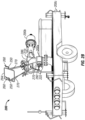
- FIG. 2A illustrates a front, left perspective view of a firewater monitor brake system 200 installed on an exemplary firewater monitor 200a, nozzle 200b and trailer 200c system according to an embodiment of the present invention
- FIG. 2B illustrates a rear, right perspective view of the firewater monitor brake system 200 of FIG. 2A
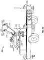
- FIG. 2C illustrates a rear, left perspective view of the firewater monitor brake system 200 of FIGS. 2A-2B
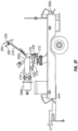
- FIG. 2D illustrates a rear view of the firewater monitor brake system 200 of FIGS. 2A-2C
- FIG. 2E illustrates an upper, left perspective view of the firewater monitor brake system 200 of FIGS. 2A-2D
- FIG. 2F illustrates a left, side view of the firewater monitor brake system 200 of FIGS. 2A-2E .
- the firewater monitor brake system 100, 200 comprises a vertical locking disc collar 110, 210, a horizontal locking disc collar 112, 212, a vertical brake mount 120, 220, a horizontal brake mount 122, 222, a vertical brake system 130, 230, a horizontal brake system 140, 240, a master cylinder 150, 250, 750, 850, a lever system 160, 260, 760, 860, 960 and an actuation system 170, 270, 970. See also FIGS. 7A-9 .
- the vertical disc locking collar 110, 210 may be any suitable shape and size.
- a suitable vertical disc locking collar 110, 210 may be shaped and sized to fit externally around a circumference (i.e., circular cross section) or an outer surface (e.g., elliptical cross section) of a horizontal waterway 182, 282 of a firewater monitor system 180, 280.
- the vertical disc locking collar 110, 210 may be ring-shaped.
- a suitable vertical disc locking collar 110, 210 may be shaped and sized to fit internally around an inner circumference (i.e., circular cross section) or an inner surface (e.g., elliptical cross section) of the horizontal waterway 182, 282 of a firewater monitor system 180, 280.
- the vertical disc locking collar 110, 210 may be ring-shaped.
- the horizontal disc locking collar 112, 212 may be any suitable shape and size.
- a suitable horizontal disc locking collar 112, 212 may be shaped and sized to fit externally around a circumference (i.e., circular cross section) or an outer surface (e.g., elliptical cross section) of a vertical waterway 184, 284 of the firewater monitor system 180, 280.
- the horizontal disc locking collar 112, 212 may be ring-shaped.
- a suitable horizontal disc locking collar 112, 212 may be shaped and sized to fit internally around an inner circumference (i.e., circular cross section) or an inner surface (e.g., elliptical cross section) of a vertical waterway 184, 284 of the firewater monitor system 180, 280.
- the horizontal disc locking collar 112, 212 may be ring-shaped.
- the vertical disc locking collar 110, 210 may be made of any suitable material.
- a suitable vertical disc locking collar 110, 210 may be made of any metal.
- the vertical locking disc collar 110, 210 may be made of stainless steel.
- the horizontal disc locking collar 112, 212 may be made of any suitable material.
- a suitable horizontal disc locking collar 112, 212 may be made of any metal.
- the horizontal locking disc collar 112, 212 may be made of stainless steel.
- the vertical locking disc collar 110, 210 may adapted to be affixed externally around the circumference (i.e., circular cross section) or the outer surface (e.g., elliptical cross section) of the horizontal waterway 182, 282 of the firewater monitor system 180, 280.
- the vertical locking disc collar 110, 210 may be affixed to a bottom of a horizontal swivel 186, 286 of the firewater monitor system 180, 280.
- the vertical locking disc collar 110, 210 may be affixed to the bottom the horizontal swivel 186, 286 via a fastener or a weld.
- the vertical locking disc collar 110, 210 may adapted to be affixed internally around the inner circumference (i.e., circular cross section) or the inner surface (e.g., elliptical cross section) of the horizontal waterway 182, 282 of the firewater monitor system 180, 280.
- the vertical locking disc collar 110, 210 may be affixed to a bottom of a horizontal swivel 186, 286 of the firewater monitor system 180, 280.
- the vertical locking disc collar 110, 210 may be affixed to the bottom the horizontal swivel 186, 286 via a fastener or a weld.
- the horizontal locking disc collar 112, 212 may be adapted to be affixed externally around the circumference (i.e., circular cross section) or the outer surface (e.g., elliptical cross section) of the vertical waterway 184, 284 of the firewater monitor system 180, 280.
- the horizontal locking disc collar 112, 212 may be affixed to a bottom of a vertical swivel 188, 288 of the firewater monitor system 180, 280.
- the horizontal locking disc collar 112, 212 may be affixed to the bottom the vertical swivel 188, 288 via a fastener or a weld.
- the horizontal locking disc collar 112, 212 may be adapted to be affixed internally around the inner circumference (i.e., circular cross section) or the inner surface (e.g., elliptical cross section) of the vertical waterway 184, 284 of the firewater monitor system 180, 280.
- the horizontal locking disc collar 112, 212 may be affixed to a bottom of the second slewing drive of the firewater monitor system 180, 280.
- the horizontal locking disc collar 112, 212 may be affixed to the bottom the second slewing drive via a fastener or a weld.
- the vertical brake mount 120, 220 may be any suitable shape and size.
- a suitable vertical brake mount 120, 220 may be shaped and sized to affix a vertical brake system 130, 230 to a horizontal swivel mounting pad 190, 290 of a firewater monitor system 180 280 such that a portion of the vertical brake system 130, 230 is disposed around a portion of the vertical locking disc collar 110, 210.
- the vertical brake mount 120, 220 may be shaped as a curved ring portion extending from a square or rectangular portion.
- the horizontal brake mount 122, 222 may be any suitable shape and size.
- a suitable horizontal brake mount 122, 222 may be shaped and sized to affix a horizontal brake system 140, 240 to a vertical swivel mounting pad 192, 292 of the firewater monitor system 180 280 such that a portion of the horizontal brake system 140, 240 is disposed around a portion of the horizontal locking disc collar 112, 212.
- the horizontal brake mount 122, 222 may be shaped as a curved ring portion extending from a square or rectangular portion.
- the vertical brake mount 120, 220 may be made of any suitable material.
- a suitable vertical brake mount 120, 220 may be made of any metal.
- the vertical brake mount 120, 220 may be made of stainless steel.
- the horizontal brake mount 122, 222 may be made of any suitable material.
- a suitable horizontal brake mount 122, 222 may be made of any metal.
- the horizontal brake mount 122, 222 may be made of stainless steel.
- the vertical brake mount 120, 220 may be adapted to be affixed to a horizontal swivel mounting pad 190, 290 of the firewater monitor system 180, 280. In an embodiment, the vertical brake mount 120, 220 may be affixed to the horizontal swivel mounting pad 190, 290 via a fastener or a weld. In an embodiment, the square or rectangular portion of the vertical brake mount 120, 220 may be affixed to the horizontal swivel mounting pad 190, 290 via a fastener or a weld.
- the horizontal brake mount 122, 222 may be adapted to be affixed to a vertical swivel mounting pad 192, 292 of the firewater monitor system 180, 280.
- the horizontal brake mount 122, 222 may be affixed to the vertical swivel mounting pad 192, 292 via a fastener or a weld.
- the square or rectangular portion of the horizontal brake mount 122, 222 may be affixed to the vertical swivel mounting pad 192, 292 via a fastener or weld.
- the vertical brake system 130, 230, 330, 430 may be any suitable brake system.
- a suitable vertical brake system 130, 230, 330, 430 includes, but is not limited to, a plate-on-plate brake system (e.g., caliper brake system, disc brake system), a meshed-teeth brake system and/or a retracting, locking pin brake system and combinations thereof.
- the vertical brake system 130, 230, 330, 430 may be in a fail-safe, resting state such that the vertical brake system 130, 230, 330, 430 may be in an "activated" or closed position, clamping the vertical locking disc collar 110, 210 with sufficient energy to prevent rotational movement of the horizontal waterway 182, 282 of the firewater monitor system 100, 200.
- the vertical brake system 130, 230, 330, 430 may be in a "deactivated” or open position, releasing the vertical locking disc collar 110, 210 to allow rotational movement of the horizontal waterway 182, 282 of the firewater monitor system 100, 200.
- FIG. 3A illustrates front view of an exemplary disc brake system 300 of the firewater monitor brake system 100, 200 according to an embodiment
- FIG. 3B illustrates bottom, right perspective view of the exemplary disc brake system 300 of FIG. 3A
- FIG. 3C illustrates bottom view of the exemplary disc brake system 300 of FIGS. 3A-3B
- FIG. 3D illustrates a detail A-A view of the exemplary disc brake system 300 of FIG. 3C .
- the vertical brake system 130, 230, 430 may be a M200 Series Caliper Brake System from W.C. Branham Inc. or equivalent.
- FIG. 4A illustrates top view of an exemplary caliper brake system 400 of the firewater monitor brake system 100, 200 according to an embodiment of the present invention
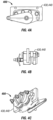
- FIG. 4B illustrates right, side view of the exemplary caliper brake system 400 of FIG. 4A
- FIG. 4C illustrates bottom, left perspective view of the exemplary caliper brake system 400 of FIGS. 4A-4B .
- the vertical brake system 130, 230 may be a meshed-teeth brake system such that a plurality of teeth on a brake plate and a plurality of like-shaped and like-sized teeth are machined into a vertical locking disc collar 110, 210.
- the horizontal brake system 140, 240, 340, 440 may be any suitable brake system.
- a suitable horizontal brake system 140, 240, 340, 440 includes, but is not limited to, a plate-on-plate brake system (e.g., caliper brake system, disc brake system), a meshed-teeth brake system and/or a retracting, locking pin brake system and combinations thereof.
- the horizontal brake system 140, 240, 340, 440 may be in a fail-safe, resting state such that the horizontal brake system 140, 240, 340, 440 may be in an "activated” or closed position, clamping the horizontal locking disc collar 112, 212 with sufficient energy to prevent rotational movement of the vertical waterway 184, 284 of the firewater monitor system 100, 200.
- the horizontal brake system 140, 240, 340, 440 may be in a "deactivated” or open position, releasing the horizontal locking disc collar 112, 212 to allow rotational movement of the vertical waterway 184, 284 of the firewater monitor system 100, 200.
- a suitable horizontal brake system 140, 240, 340, 440 is available from W.C. Branham Inc.
- the horizontal brake system 140, 240, 340 may be a FS200 Series Disc Brake System from W.C. Branham Inc. or equivalent. See also FIGS. 3A-3D .
- the horizontal brake system 140, 240, 440 may be a M200 Series Caliper Brake System from W.C. Branham Inc. or equivalent. See also FIGS. 4A-4C .
- the vertical master cylinder 152, 252, 552, 752, 852 may be any suitable master cylinder.
- a suitable vertical master cylinder 152, 252, 552, 752, 852 includes, but is not limited to, a hydraulic master cylinder (see FIGS. 7-8 ), and a radial master cylinder (see FIGS. 1F , 2A-2F & 5 ).
- a suitable vertical master cylinder 152, 252, 552 is available from Brembo SpA.
- the vertical master cylinder 152, 252, 552 may be a Radial Master Cylinder from Brembo SpA or equivalent.
- the horizontal master cylinder 154, 254, 554, 754, 854 may be any suitable master cylinder.
- a suitable horizontal master cylinder 154, 254, 554, 754, 854 includes, but is not limited to, a hydraulic master cylinder (see FIGS. 7-8 ), and a radial master cylinder (see FIGS. 1F , 2A-2F & 5 ).
- a suitable horizontal master cylinder 154, 254, 554 is available from Brembo SpA.
- the horizontal master cylinder 154, 254, 553 may be a Radial Master Cylinder from Brembo SpA or equivalent.
- FIG. 1F is a detail view of an exemplary lever system for the firewater monitor brake system of FIGS. 1A-1E ; and FIG. 5 is a side view of an exemplary radial master cylinder having a lever system of the firewater monitor brake system.
- FIG. 7A is a side view of another exemplary lever system for the firewater monitor brake system according to an embodiment of the present invention
- FIG. 7B is a top view of the exemplary lever system of FIG. 7A
- FIG. 7C is a front view of the exemplary lever system of FIGS. 7A-7B , showing the lever system in an disengaged position.
- FIG. 8A is a side view of the exemplary lever system of FIGS. 7A-7C ;
- FIG. 8B is a top view of the exemplary lever system of FIGS. 7A-7C and 8A ;
- FIG. 8C is a front view of the exemplary lever system of FIGS. 7A-7C and 8A-8B , showing the lever system in an engaged position.
- FIG. 9 illustrates an upper, side perspective view of another exemplary lever system of the firewater monitor brake system according to an embodiment of the present invention, showing a foot operated lever system in a disengaged position.
- the lever system 160, 260, 560, 760, 860 may be a hand operated lever system; and a lever system 960 may be a foot operated lever system. See FIGS. 1A, 1F-1G , 2A-2F , 5 & 7A-9 .
- the lever system 160, 260, 760, 860 may be any suitable lever system.
- a suitable lever system 160, 260, 760, 860 includes, but is not limited to, a caliper-style lever system (see FIGS. FIGS. 1A, 1F-1G , 2A-2F & 5 ), a side-to-side handle-style (e.g., lawn mower lever) lever system (see FIGS. 7A-8C ), a top-to-bottom-style lever system and combinations thereof.
- a suitable caliper-style lever system 160, 260 is available from Brembo SpA.
- the lever system 160, 260 may be part of a Radial Master Cylinder from Brembo SpA.
- the lever system 960 may be any suitable lever system.
- a suitable lever system 960 includes, but is not limited to, a button-style (e.g., anchor windlass) lever system (see FIG. 9 ), a pedal-style (e.g., sewing machine pedal) lever system and combinations thereof.
- the vertical lever system 162, 262, 562, 762, 862 may be any suitable lever system.
- a suitable vertical lever system 162, 262, 562, 762, 862 includes, but is not limited to, a caliper-style lever system (see FIGS. 1A, 1F-1G , 2A-2F & 5 ), a side-to-side handle-style (e.g., lawn mower lever) lever system (see FIGS. 7A-8C ), a top-to-bottom-style lever system and combinations thereof.
- a suitable caliper-style vertical lever system 162, 262, 562 is available from Brembo SpA.
- the vertical lever system 162, 262, 562 may be part of a Radial Master Cylinder from Brembo SpA.
- the vertical lever system 962 may be any suitable lever system.
- a suitable vertical lever system 962 includes, but is not limited to, a button-style (e.g., anchor windlass) lever system (see FIG. 9 ), a pedal-style (e.g., sewing machine pedal) lever system and combinations thereof.
- the horizontal lever system 164, 264, 564, 764, 864 may be any suitable lever system.
- a suitable horizontal lever system 164, 264, 564, 764, 864 includes, but is not limited to, a caliper-style lever system (see FIGS. 1A, 1F-1G , 2A-2F & 5 ), a side-to-side handle-style (e.g., lawn mower lever) lever system (see FIGS. 7A-8C ), a top-to-bottom-style lever system and combinations thereof.
- a suitable caliper-style horizontal lever system 164, 264, 564 is available from Brembo SpA.
- the horizontal lever system 164, 264, 564 may be part of a Radial Master Cylinder from Brembo SpA.
- the horizontal lever system 964 may be any suitable lever system.
- a suitable horizontal lever system 964 includes, but is not limited to, a button-style (e.g., anchor windlass) lever system (see FIG. 9 ), a pedal-style (e.g., sewing machine pedal) lever system and combinations thereof.
- the lever system 160, 260, 760, 860 may be adapted to be affixed to a tiller bar 194, 294, 794, 894 of the firewater monitor system 180, 280.
- the vertical lever system 162, 262, 762, 862 may be adapted to be affixed to a tiller bar 194, 294, 794, 894 of the firewater monitor system 180, 280.
- the horizontal lever system 164, 264, 764, 864 may be adapted to be affixed to a tiller bar 194, 294, 794, 894 of the firewater monitor system 180, 280.
- the lever system 160, 260, 760, 860, 960 may be fluidly (i.e., hydraulic, pneumatic) connected to and/or mechanically (e.g., cable linkage) coupled to the master cylinder 150, 250, 750, 850 via an actuation system 170, 270, 970.
- the vertical lever system 162, 262, 762, 862, 962 may be fluidly (i.e., hydraulic, pneumatic) connected to and/or mechanically (e.g., cable linkage) coupled to the vertical master cylinder 152, 252, 752, 852 via a vertical actuation system 172, 272, 972.
- the horizontal lever system 164, 264, 764, 864, 964 may be fluidly (i.e., hydraulic, pneumatic) connected to and/or mechanically (e.g., cable linkage) coupled to the horizontal master cylinder 154, 254, 754, 854 via the horizontal actuation system 174, 274, 974.
- the master cylinder 150, 250, 750, 850 may be fluidly (i.e., hydraulic, pneumatic) connected to and/or mechanically (e.g., cable linkage) coupled to the vertical brake system 130, 230 and/or the horizontal brake system 140, 240 via the actuation system 170, 270, 970.
- the vertical master cylinder 152, 252, 752, 754 may be fluidly (i.e., hydraulic, pneumatic) connected to and/or mechanically (e.g., cable linkage) coupled to the vertical brake system 130, 230 via the vertical actuation system 172, 272, 972.
- the horizontal master cylinder 154, 254, 754, 854 may be fluidly (i.e., hydraulic, pneumatic) connected to and/or mechanically (e.g., cable linkage) coupled to the horizontal brake system 140, 240 via the horizontal actuation system 174, 274, 974.
- the actuation system 170, 270, 970 may be any suitable actuation system.
- a suitable actuation system 170, 270, 970 includes, but is not limited to, cable linkage systems, hydraulic systems (see FIGS. 1A, 1D-1F & 9 ), and pneumatic systems.
- the vertical actuation system 172, 272, 972 may be any suitable actuation system.
- a suitable vertical actuation system 172, 272, 972 includes, but is not limited to, cable linkage systems, hydraulic systems (see FIGS. 1A, 1D-1F & 9 ), and pneumatic systems.
- the horizontal actuation system 174, 274, 974 may be any suitable actuation system.
- a suitable horizontal actuation system 174, 274, 974 includes, but is not limited to, cable linkage systems, hydraulic systems (see FIGS. 1A, 1D-1F & 9 ), and pneumatic systems.
- FIG. 6A illustrates a flow chart of an exemplary method of using the firewater monitor brake system 600 of FIGS. 1A-5 according to an embodiment of the present invention
- FIG. 6B illustrates a flow chart of another exemplary method of using the firewater monitor brake system 600 of FIGS. 1A-5
- FIG. 6C illustrates a flow chart of another exemplary method of the using the firewater brake system 600 of FIGS. 1A-5
- FIG. 6D illustrates a flow chart of another exemplary method of the using the firewater brake system 600 of FIGS. 1A-5 .
- the method of using a firewater monitor brake system 600 comprises:
- the method 600 further comprises: c) releasing one or more lever to activate the vertical brake and/or the horizontal brake 630. See FIG. 6B . In an embodiment, the method 600 comprises c) releasing the vertical lever to activate the vertical brake 632. See FIG. 6D . In an embodiment, the method 600 comprises c) releasing the horizontal lever to activate the horizontal brake 634. Id.
- the method of using a firewater monitor brake system 600 comprises:
- the method 600 further comprises: c) releasing one or more vertical lever and/or horizontal lever to activate the vertical brake and/or the horizontal brake 630. See FIG. 6B . In an embodiment, the method 600 comprises c) releasing the vertical lever to activate the vertical brake 632. See FIG. 6D . In an embodiment, the method 600 comprises c) releasing the horizontal lever to activate the horizontal brake 634. Id.
- Coupled means the joining of two members directly or indirectly to one another. Such joining may be stationary (e.g., permanent or fixed) or moveable (e.g., removable or releasable). Such joining may be achieved with the two members coupled directly to each other, with the two members coupled to each other using a separate intervening member and any additional intermediate members coupled with one another, or with the two members coupled to each other using an intervening member that is integrally formed as a single unitary body with one of the two members.
- Coupled or variations thereof are modified by an additional term (e.g., directly coupled)
- the generic definition of “coupled” provided above is modified by the plain language meaning of the additional term (e.g., "directly coupled” means the joining of two members without any separate intervening member), resulting in a narrower definition than the generic definition of "coupled” provided above.
- Such coupling may be mechanical, electrical, or fluidic.
Landscapes
- Engineering & Computer Science (AREA)
- General Engineering & Computer Science (AREA)
- Health & Medical Sciences (AREA)
- Public Health (AREA)
- Business, Economics & Management (AREA)
- Emergency Management (AREA)
- Mechanical Engineering (AREA)
- Transportation (AREA)
- Braking Arrangements (AREA)
Abstract
Description
- This application claims the benefit of
U.S. Provisional Patent Application Serial No. 62/760,675, entitled "FIREWATER MONITOR BRAKE SYSTEM AND METHOD," filed on November 13, 2018 - The present disclosure relates generally to fire water monitors. More specifically, the present disclosure relates a firewater monitor brake system and method.
- Firewater monitors range in size - flowing from hundreds to tens of thousands of gallons of water flow per minute. Firewater monitors offer motive water flow to a nozzle affixed to the monitor tip for delivering water and/or extinguishing agents as a mitigating factor onto an airborne hazard and/or fire.
- Monitor designs include both manually-operated and motor-actuated configurations.
- Motor-actuated monitors are controlled by protected electric, hydraulic or pneumaticactuated gear mechanisms that produce vertical and horizontal travel, determining positon while also limiting free movement of the monitor along its course of travel.
- Manually-operated monitors may also include gear mechanisms for controlling monitor travel, where gears are manipulated manually by hand by an operator. Pace of movement along both horizontal and vertical axes for gear-operated monitors is limited by the mechanical ratio of the controlling gears.
- In lieu of gears, manually-operated monitors may also include a tiller bar design-a single point of contact with the monitor either by one controller bar or lever, or by a dual, handle-bar style controller used by an operator to control monitor movement more freely along both vertical and horizontal axes. This monitor design allows for more rapid, free movement along both axes and commonly relies on manual locking mechanisms to fix and to secure the monitor positon - one lock for vertical travel and a second lock for horizontal travel. This tiller-bar styled monitor offers the benefit of rapid monitor movement by the operator. In fire response, this rapid response capability is preferred in a manned response effort to assure prompt critical life safety controls against what is commonly an ever changing threat.
- While tiller bar control over the fire monitor is quicker and more responsive, as monitor size and flow rates increase, the monitor becomes more difficult to control with manual monitor brake systems. An automated, fail-safe monitor brake system that is more ergonomic and easy to use would be ideal, particularly, for larger monitors with higher flow rates.
- Therefore, there is a need for an automatic firewater monitor brake system and method.
- The firewater monitor brake system and method of the present invention offers an automated, fail-safe safety mechanism that locks the position of a manually-operated monitor in the event of loss of control by the operator.
- Mechanical in nature, the firewater monitor brake system may comprise one or more brake system, each activated and deactivated by one or more lever system, which opens or closes each brake system around a "locking disc" collar. One locking disc collar may be affixed externally around a circumference (i.e., circular cross section) or an outer surface (e.g., elliptical cross section) of a horizontal waterway of a firewater monitor system; and another locking disc collar may be affixed externally around a circumference (i.e., circular cross section) or an outer surface (e.g., elliptical cross section) of a vertical waterway of the firewater monitor system.
- Alternatively, when the monitor uses a first slewing drive for the horizontal waterway and a second slewing drive for the vertical water way, one locking disc collar may be affixed internally around an inner circumference (i.e., circular cross section) or an inner surface (e.g., elliptical cross section) of a horizontal waterway of a firewater monitor system; and another locking disc collar may be affixed internally around an inner circumference (i.e., circular cross section) or an inner surface (e.g., elliptical cross section) of a vertical waterway of the firewater monitor system.
- Each brake system has an open and a closed position. The closed or "actuated" position of the brake system is its "resting state," which clamps the locking disc collar with sufficient energy as to prohibit rotational movement of the monitor waterway around its particular axis. When the brake system is "deactivated" to its open position by depressing the lever system, the brake system releases the locking disc collar allowing free movement of the monitor waterway around is particular axis. Again, intentional or accidental release of one or more lever system actuates the brake system, thereby, clamping down on one or more locking discs collars to stop / lock the firewater monitor system's position and prevent further travel in either the horizontal and/or vertical direction.
- Operation of the firewater monitor brake system may be integrated into the firewater monitor system's handle-bar styled controller as an ergonomic accessory lever system that will simultaneously activate and deactivate one or more brake systems. While gripping the firewater monitor system's handle bar for normal operation, this lever system may be depressed naturally, thereby, deactivating one or more brake system to its open position, which allows controlled monitor movement by the operator. When one or more lever system is released - either intentionally or accidently - the one or more brake system activates to a closed position immediately stopping / locking the firewater monitor system's position and preventing further travel in either the horizontal and/or vertical direction.
- At least one embodiment relates to a firewater monitor brake system comprises: a vertical locking disc collar adapted to be affixed externally or internally to a horizontal swivel of a firewater monitor system; a horizontal locking disc collar adapted to be affixed externally or internally to a vertical swivel of the firewater monitor system; a vertical brake mount adapted to be affixed to a horizontal swivel mounting pad of the firewater monitor system; a horizontal brake mount adapted to be affixed to a vertical swivel mounting pad of the firewater monitor system; a vertical brake system; wherein the vertical brake system is affixed to the vertical brake mount such that a portion of the vertical brake system is disposed around a portion of the vertical locking disc collar; a horizontal brake system, wherein the horizontal brake system is affixed to the horizontal brake mount such that a portion of the horizontal brake system is disposed around a portion of the horizontal locking disc collar; and a master cylinder adapted to be affixed to a tiller bar of the firewater monitor system, wherein the master cylinder is connected to and/or coupled to a lever system and wherein the master cylinder is connected to and or coupled to the vertical brake system and/or the horizontal brake system via an actuation system.
- In an embodiment, the vertical brake system is selected from the group consisting of a plate-on-plate brake system, a meshed-teeth brake system, a retracting, locking pin brake system and combinations thereof. In an embodiment, the horizontal brake system is selected from the group consisting of a plate-on-plate brake system, a meshed-teeth brake system, a retracting, locking pin brake system and combinations thereof. In an embodiment, one or more of the vertical brake system and the horizontal brake system is a caliper brake system. In an embodiment, one or more of the vertical brake system and the horizontal brake system is a disc brake system. In an embodiment, one or more of the vertical brake system and the horizontal brake system is a meshed-teeth braking system. In an embodiment, one or more of the vertical brake system and the horizontal brake system is a retracting, locking pin brake system.
- In an embodiment, one or more of the vertical brake system and the horizontal brake system is capable of an activated, closed position, clamping the vertical locking disc collar and/or the horizontal locking collar with sufficient energy to prevent rotational movement of a horizontal waterway and/or a vertical waterway of the firewater monitor system. In an embodiment, one or more of the vertical brake system and the horizontal brake system is capable of a deactivated, open position, releasing the vertical locking disc collar and/or the horizontal locking collar to allow rotational movement of a horizontal waterway and/or a vertical waterway of the firewater monitor system.
- In an embodiment, the master cylinder is a hydraulic master cylinder or radial master cylinder. In an embodiment, the master cylinder is a hydraulic master cylinder. In an embodiment, the master cylinder is a radial master cylinder.
- In an embodiment, the lever system may be hand or foot operated. In an embodiment, the lever system is hand operated. In an embodiment, the lever system is foot operated.
- In an embodiment, the lever system is selected of the group consisting of a caliper-style lever system, a side-to-side handle-style lever system, a top-to-bottom-style lever system and combinations thereof. In an embodiment, the lever system is a caliper-style lever system. In an embodiment, the lever system is a side-to-side handle-style (e.g., lawn mower lever) lever system. In an embodiment, the lever system is a top-to-bottom handle-style lever system.
- In an embodiment, the lever system is selected from the group consisting of a button-style (e.g., anchor windlass) lever system, a pedal-style (e.g., sewing machine pedal) lever system and combinations thereof.
- In an embodiment, the actuation system is selected from the group of cable-linkage systems, hydraulic systems, pneumatic systems and combinations thereof. In an embodiment, the actuation system is a cable-linkage system. In an embodiment, the actuation system is a hydraulic system. In an embodiment, the actuation system is a pneumatic system.
- Another embodiment relates to a method of using the firewater monitor brake system comprises: providing the firewater monitor brake system, as discussed herein; and depressing one or more lever to deactivate the vertical brake and/or the horizontal brake.
- In an embodiment, the method further comprises: releasing one or more lever to activate the vertical brake and/or the horizontal brake.
- In an embodiment, the method comprises: depressing a vertical lever to deactivate the vertical brake. In an embodiment, the method further comprises: releasing the vertical lever to activate the vertical brake.
- In an embodiment, the method comprises depressing a horizontal lever to deactivate the horizontal brake. In an embodiment, the method further comprises: releasing a horizontal lever to activate the horizontal brake.
- This summary is illustrative only and is not intended to be in any way limiting. Other aspects, inventive features, and advantages of the devices or processes described herein will become apparent in the detailed description set forth herein, taken in conjunction with the accompanying figures, wherein like reference numerals refer to like elements.
- These and other objects, features and advantages will become apparent as reference is made to the following detailed description, preferred embodiments, and examples, given for the purpose of disclosure, and taken in conjunction with the accompanying drawings and appended claims.
- Clause 1. A firewater monitor brake system, comprising:
- a) a vertical locking disc collar adapted to be affixed externally or internally to a horizontal swivel of a firewater monitor system;
- b) a horizontal locking disc collar adapted to be affixed externally or internally to a vertical swivel of the firewater monitor system;
- c) a vertical brake mount adapted to be affixed to a horizontal swivel mounting pad of the firewater monitor system;
- d) a horizontal brake mount adapted to be affixed to a vertical swivel mounting pad of the firewater monitor system;
- e) a vertical brake system; wherein the vertical brake system is affixed to the vertical brake mount such that a portion of the vertical brake system is disposed around a portion of the vertical locking disc collar;
- f) a horizontal brake system, wherein the horizontal brake system is affixed to the horizontal brake mount such that a portion of the horizontal brake system is disposed around a portion of the horizontal locking disc collar; and
- g) a master cylinder adapted to be affixed to a tiller bar of the firewater monitor system, wherein the master cylinder is connected to and/or coupled to a lever system and wherein the master cylinder is connected to and or coupled to the vertical brake system and/or the horizontal brake system via an actuation system.
- Clause 2. The system of clause 1, wherein the vertical brake system is selected from the group consisting of a plate-on-plate brake system, a meshed-teeth brake system, a retracting, locking pin brake system and combinations thereof.
- Clause 3. The system of clause 1, wherein the horizontal brake system is selected from the group consisting of a plate-on-plate brake system, a meshed-teeth brake system, a retracting, locking pin brake system and combinations thereof.
- Clause 4. The system of clause 1, wherein one or more of the vertical brake system and the horizontal brake system is a caliper brake system.
- Clause 5. The system of clause 1, wherein one or more of the vertical brake system and the horizontal brake system is a disc brake system.
- Clause 6. The system of clause 1, wherein one or more of the vertical brake system and the horizontal brake system is a meshed-teeth braking system.
- Clause 7. The system of clause 1, wherein one or more of the vertical brake system and the horizontal brake system is a retracting, locking pin brake system.
- Clause 8. The system of clause 1, wherein one or more of the vertical brake system and the horizontal brake system is capable of an activated, closed position, clamping the vertical locking disc collar and/or the horizontal locking collar with sufficient energy to prevent rotational movement of a horizontal waterway and/or a vertical waterway of the firewater monitor system.
- Clause 9. The system of clause 1, wherein one or more of the vertical brake system and the horizontal brake system is capable of a deactivated, open position, releasing the vertical locking disc collar and/or the horizontal locking collar to allow rotational movement of a horizontal waterway and/or a vertical waterway of the firewater monitor system.
- Clause 10. The system of clause 1, wherein the master cylinder is a hydraulic master cylinder.
- Clause 11. The system of clause 1, wherein the master cylinder is a radial master cylinder.
- Clause 12. The system of clause 1, wherein the lever system is selected of the group consisting of a caliper-style lever system, a side-to-side handle-style lever system, a top-to-bottom-style lever system and combinations thereof.
- Clause 13. The system of clause 1, wherein the lever system is a caliper-style lever system.
- Clause 14. The system of clause 1, wherein the lever system is a side-to-side handle-style lever system.
- Clause 15. The system of clause 1, wherein the lever system is a top-to-bottom handle-style lever system.
- Clause 16. The system of clause 1, wherein the lever system is selected from the group consisting of a button-style lever system, a pedal-style lever system and combinations thereof.
- Clause 17. The system of clause 1, wherein the lever system is a button-style lever system.
- Clause 18. The system of clause 1, wherein the lever system is a pedal-style lever system.
- Clause 19. The system of clause 1, wherein the actuation system is selected from the group of cable-linkage systems, hydraulic systems, pneumatic systems and combinations thereof.
- Clause 20. The system of clause 1, wherein the actuation system is a cable-linkage system.
- Clause 21. The system of clause 1, wherein the actuation system is a hydraulic system.
- Clause 22. The system of clause 1, wherein the actuation system is a pneumatic system.
- Clause 23. A method, comprising:
- a) providing the system of clause 1; and
- b) depressing one or more lever to deactivate the vertical brake and/or the horizontal brake.
- Clause 24. The method of clause 23 further comprising:
c) releasing one or more lever to activate the vertical brake and/or the horizontal brake. - Clause 25. The method of clause 23, wherein step b) comprises depressing a vertical lever to deactivate the vertical brake.
- Clause 26. The method of clause 23, wherein step b) comprises depressing a horizontal lever to deactivate the horizontal brake.
- Clause 27. The method of clause 25, wherein step c) comprises releasing the vertical lever to activate the vertical brake.
- Clause 28. The method of clause 26, wherein step c) comprises releasing a horizontal lever to activate the horizontal brake.
- Clause 29. A firewater monitor brake system, comprising:
- a firewater monitor comprising a horizontal waterway;
- a horizontal swivel coupled to the horizontal waterway;
- a tiller bar coupled to the firewater monitor;
- a horizontal brake, wherein the horizontal brake is adapted to be affixed externally or internally to the horizontal swivel;
- a horizontal actuation system coupled to the horizontal brake; and
- a horizontal brake lever movably attached to the tiller bar, wherein the horizontal brake lever is coupled to the horizontal brake via the horizontal actuation system such that the horizontal brake locks the horizontal swivel responsive to the horizontal brake lever being released.
- Clause 30. The system of clause 29, wherein the horizontal brake is a plate-on-plate brake system.
- Clause 31. The system of clause 29, wherein the horizontal brake is a caliper brake system.
- Clause 32. The system of clause 29, wherein the horizontal brake is a disc brake system.
- Clause 33. The system of clause 29, further comprising a horizontal locking disc collar coupled to the horizontal swivel, wherein the horizontal brake is capable of an activated, closed position, clamping the horizontal locking disc collar with sufficient energy to prevent rotational movement of the horizontal waterway.
- Clause 34. The system of clause 29, further comprising a horizontal locking disc collar coupled to the horizontal swivel, wherein the horizontal brake is capable of a deactivated, open position, releasing the horizontal locking disc collar to allow rotational movement of the horizontal waterway.
- Clause 35. The system of clause 29, wherein the horizontal actuation system is selected from the group consisting of a cable-linkage system, a hydraulic system, a pneumatic system, and combinations thereof.
- Clause 36. The system of clause 29, further comprising a master cylinder adapted to be affixed to the tiller bar, wherein the master cylinder is connected to and/or coupled to the horizontal brake lever and wherein the master cylinder is connected to and/or coupled to the horizontal brake via the horizontal actuation system.
- Clause 37. The firewater monitor brake system of clause 29, wherein the firewater monitor further comprises a vertical waterway, further comprising:
- a vertical swivel coupled to the vertical waterway;
- a vertical brake, wherein the vertical brake is adapted to be affixed externally or internally to the vertical swivel;
- a vertical actuation system coupled to the vertical brake; and
- a vertical brake lever movably attached to the tiller bar, wherein the vertical brake lever is coupled to the vertical brake via the vertical actuation system such that the vertical brake locks the vertical swivel responsive to the vertical brake lever being released.
- Clause 38. The system of clause 37, wherein the vertical brake is selected from the group comprising a plate-on-plate brake system, a caliper brake system, and a disc brake system.
- Clause 39. The system of clause 37, further comprising a vertical locking disc collar coupled to the vertical swivel, wherein the vertical brake is capable of an activated, closed position, clamping the vertical locking disc collar with sufficient energy to prevent rotational movement of the vertical waterway.
- Clause 40. The system of clause 37, further comprising a vertical locking disc collar coupled to the vertical swivel, wherein the vertical brake system is capable of a deactivated, open position, releasing the vertical locking disc collar to allow rotational movement of the vertical waterway.
- Clause 41. The system of clause 37, wherein the vertical actuation system is selected from the group consisting of a cable-linkage system, a hydraulic system, a pneumatic system, and combinations thereof.
- Clause 42. The system of clause 37, further comprising a master cylinder adapted to be affixed to the tiller bar, wherein the master cylinder is connected to and/or coupled to the vertical brake lever and wherein the master cylinder is connected to and/or coupled to the vertical brake via the vertical actuation system.
- Clause 43. The system of clauses 36 or 42, wherein the master cylinder is a radial master cylinder.
- Clause 44. A firewater monitor brake system, comprising:
- a horizontal brake system comprising a horizontal brake, wherein the horizontal brake is adapted to be affixed to a vertical swivel of a firewater monitor system;
- a horizontal brake mount configured to affix the horizontal brake system to the vertical swivel;
- a master cylinder adapted to be affixed to a tiller bar of the firewater monitor system and a horizontal lever system comprising a horizontal lever; wherein the master cylinder is connected to and/or coupled to the horizontal lever system; and wherein the master cylinder is connected to and or coupled to the horizontal brake system via a horizontal actuation system, such that depressing the horizontal lever deactivates the horizontal brake.
- Clause 45. The firewater monitor brake system of clause 44, further comprising:
- a vertical brake system comprising a vertical brake, wherein the vertical brake is adapted to be affixed to a horizontal swivel of a firewater monitor system;
- a vertical brake mount configured to affix the vertical brake system to the horizontal swivel;
- a vertical lever system attached to a tiller bar of the firewater monitor system;
- a master cylinder adapted to be affixed to a tiller bar of the firewater monitor system and a vertical lever system comprising a vertical lever;
- wherein the master cylinder is connected to and/or coupled to the vertical lever system and wherein the master cylinder is connected to and or coupled to the vertical brake system via a vertical actuation system, such that depressing the vertical lever deactivates the vertical brake.
- Clause 46. The system of claim clause 44, wherein the horizontal brake system is a plate-on-plate brake system.
- Clause 47. The system of clause 45, wherein the vertical brake system is a plate-on-plate brake system.
- Clause 48. The system of clause 44, wherein the horizontal brake system is a caliper brake system.
- Clause 49. The system of clause 45, wherein the vertical brake system is a caliper brake system
Clause 50. The system of clause 44, wherein the horizontal brake system is a disc brake system. - Clause 51. The system of clause 45, wherein the vertical brake system is a disc brake system.
- Clause 52. The system of clause 44, wherein the horizontal brake system is capable of an activated, closed position, clamping a horizontal locking disc collar with sufficient energy to prevent rotational movement of a horizontal waterway and/or a vertical waterway of the firewater monitor system.
- Clause 53. The system of clause 44, wherein the horizontal brake system is capable of a deactivated, open position, releasing a horizontal locking disc collar to allow rotational movement of a horizontal waterway and/or a vertical waterway of the firewater monitor system.
- Clause 54. The system of clause 45, wherein one or more of the horizontal brake system and the vertical brake system is capable of an activated, closed position, clamping a horizontal locking disc collar and/or a vertical locking disc collar with sufficient energy to prevent rotational movement of a horizontal waterway and/or a vertical waterway of the firewater monitor system.
- Clause 55. The system of clause 45, wherein one or more of the horizontal brake system and the vertical brake system is capable of a deactivated, open position, releasing a horizontal locking disc collar and/or a vertical locking disc collar to allow rotational movement of a horizontal waterway and/or a vertical waterway of the firewater monitor system.
- Clause 56. The system of clause 44, wherein the master cylinder is a hydraulic master cylinder.
- Clause 57. The system of clause 44, wherein the master cylinder is a radial master cylinder.
- Clause 58. The system of clause 45, wherein the master cylinder is a hydraulic master cylinder.
- Clause 59. The system of clause 45, wherein the master cylinder is a radial master cylinder.
- Clause 60. The system of clause 44, wherein the horizontal actuation system is selected from the group consisting of a cable-linkage system, a hydraulic system, a pneumatic system, and combinations thereof.
- Clause 61. The system of clause 45, wherein the vertical actuation system is selected from the group consisting of a cable-linkage system, a hydraulic system, a pneumatic system, and combinations thereof.
- For a further understanding of the nature and objects of the present invention, reference should be made to the following detailed disclosure, taken in conjunction with the accompanying drawings, in which like parts are given like reference numerals, and wherein:
-
FIG. 1A is a rear, upper perspective view of an exemplary firewater monitor brake system according to an embodiment of the present invention; -
FIG. 1B is a detail view of an exemplary brake mount system for the firewater monitor brake system ofFIG. 1A ; -
FIG. 1C is a detail view of an exemplary locking disc collar for the firewater monitor brake ofFIGS. 1A-1B ; -
FIG. 1D is a detail view of an exemplary horizontal brake system, exemplary horizontal brake mount and an exemplary horizontal locking disc collar for the firewater monitor brake system ofFIGS. 1A-1C ; -
FIG. 1E is a detail view of an exemplary vertical brake system, an exemplary vertical brake mount and an exemplary vertical locking disc collar for the firewater monitor brake system ofFIGS. 1A-1D ; -
FIG. 1F is a detail view of an exemplary lever system for the firewater monitor brake system ofFIGS. 1A-1E ; -
FIG. 1G is detail view of an exemplary actuation system for the firewater monitor brake system ofFIG. 1A ; -
FIG. 1H is a rear, upper perspective view of the firewater monitor brake system ofFIGS. 1A-1F installed on an exemplary firewater monitor, nozzle and trailer system according to an embodiment of the present invention; -
FIG. 2A is a front, left perspective view of a firewater monitor brake system installed on an exemplary firewater monitor, nozzle and trailer system according to an embodiment of the present invention; -
FIG. 2B is a rear, right perspective view of the firewater monitor brake system ofFIG. 2A ; -
FIG. 2C is a rear, left perspective view of the firewater monitor brake system ofFIGS. 2A-2B ; -
FIG. 2D is a rear view of the firewater monitor brake system ofFIGS. 2A-2C ; -
FIG. 2E is an upper, left perspective view of the firewater monitor brake system ofFIGS. 2A-2D ; -
FIG. 2F is a left, side view of the firewater monitor brake system ofFIGS. 2A-2E ; -
FIG. 3A is a front view of an exemplary disc brake system of the firewater monitor brake system according to an embodiment of the present invention; -
FIG. 3B is s bottom, right perspective view of the exemplary disc brake system ofFIG. 3A ; -
FIG. 3C is a bottom view of the exemplary disc brake system ofFIGS. 3A-3B ; -
FIG. 3D is a detail A-A view of the exemplary disc brake system ofFIG. 3C ; -
FIG. 4A is a top view of an exemplary caliper brake system of the firewater monitor brake system according to an embodiment of the present invention; -
FIG. 4B is a right, side view of the exemplary caliper brake system ofFIG. 4A ; -
FIG. 4C is a bottom, left perspective view of the exemplary caliper brake system ofFIGS. 4A-4B ; -
FIG. 5 is a side view of an exemplary radial master cylinder having a lever system of the firewater monitor brake system according to an embodiment of the present invention; -
FIG. 6A is a flow chart of an exemplary method of using the firewater monitor brake system ofFIGS. 1A-5 according to an embodiment of the present invention; and -
FIG. 6B is a flow chart of another exemplary method of using the firewater monitor brake system ofFIGS. 1A-5 ; -
FIG. 6C is a flow chart of another exemplary method of the using the firewater brake system ofFIGS. 1A-5 ; -
FIG. 6D is a flow chart of another exemplary method of the using the firewater brake system ofFIGS. 1A-5 ; -
FIG. 7A is a side view of another exemplary lever system for the firewater monitor brake system according to an embodiment of the present invention, showing the lever system in a disengaged position; -
FIG. 7B is a top view of the exemplary lever system ofFIG. 7A , showing the lever system in a disengaged position; -
FIG. 7C is a front view of the exemplary lever system ofFIGS. 7A-7B , showing the lever system in the disengaged position; -
FIG. 8A is a side view of the exemplary lever system ofFIGS. 7A-7C , showing the lever system in an engaged position; -
FIG. 8B is a top view of the exemplary lever system ofFIGS. 7A-7C and8A , showing the lever system in the engaged position; -
FIG. 8C is a front view of the exemplary lever system ofFIGS. 7A-7C and8A-8B , showing the lever system in the engaged position; and -
FIG. 9 illustrates an upper, side perspective view of another exemplary lever system of the firewater monitor brake system according to an embodiment of the present invention, showing a foot operated lever system in a disengaged position. - Before turning to the figures, which illustrate certain exemplary embodiments in detail, it should be understood that the present disclosure is not limited to the details or methodology set forth in the description or illustrated in the figures. It should also be understood that the terminology used herein is for the purpose of description only and should not be regarded as limiting.
- Accordingly, it is not intended that the scope of the claims appended hereto be limited to the examples and descriptions set forth herein but rather that the claims be construed as encompassing all the features of patentable novelty which reside in the present invention, including all features which would be treated as equivalents thereof by those skilled in the art to which the invention pertains. Therefore, the scope of the present invention is defined only by the appended claims, along with the full scope of equivalents to which such claims are entitled.
-
FIG. 1A illustrates a rear, upper perspective view of a firewatermonitor brake system 100 according to an embodiment of the present invention;FIG. 1B illustrates a detail view of anexemplary brake mount monitor brake system 100 ofFIG. 1A; FIG. 1C illustrates a detail view of an exemplarylocking disc collar monitor brake system 100 ofFIGS. 1A-1B; FIG. 1D illustrates a detail view of an exemplaryhorizontal brake system 140, exemplaryhorizontal brake mount 122 and an exemplary horizontallocking disc collar 112 for the firewatermonitor brake system 100 ofFIGS. 1A-1C; FIG. 1E illustrates a detail view of an exemplaryvertical brake system 130, an exemplaryvertical brake mount 120 and an exemplary verticallocking disc collar 110 for the firewatermonitor brake system 100 ofFIGS. 1A-1D; FIG. 1F illustrates a detail view of anexemplary lever system 160 for the firewatermonitor brake system 100 ofFIGS. 1A-1E; FIG. 1G illustrates detail view of anexemplary actuation system 170 for the firewatermonitor brake system 100 ofFIG. 1A ; andFIG. 1H illustrates a rear, upper perspective view of the firewatermonitor brake system 100 ofFIGS. 1A-1F installed on anexemplary firewater monitor 100a,nozzle 100b andtrailer 100c system according to an embodiment of the present invention; -
FIG. 2A illustrates a front, left perspective view of a firewatermonitor brake system 200 installed on anexemplary firewater monitor 200a,nozzle 200b andtrailer 200c system according to an embodiment of the present invention;FIG. 2B illustrates a rear, right perspective view of the firewatermonitor brake system 200 ofFIG. 2A ;FIG. 2C illustrates a rear, left perspective view of the firewatermonitor brake system 200 ofFIGS. 2A-2B ;FIG. 2D illustrates a rear view of the firewatermonitor brake system 200 ofFIGS. 2A-2C ;FIG. 2E illustrates an upper, left perspective view of the firewatermonitor brake system 200 ofFIGS. 2A-2D ; andFIG. 2F illustrates a left, side view of the firewatermonitor brake system 200 ofFIGS. 2A-2E . - As shown in
FIGS. 1A-1H andFIGS. 2A-2F , the firewatermonitor brake system locking disc collar locking disc collar vertical brake mount horizontal brake mount vertical brake system horizontal brake system master cylinder lever system actuation system FIGS. 7A-9 . - The vertical
disc locking collar disc locking collar horizontal waterway firewater monitor system 180, 280. In an embodiment, the verticaldisc locking collar - Alternatively, when the monitor uses a first slewing drive for the horizontal waterway, a suitable vertical
disc locking collar horizontal waterway firewater monitor system 180, 280. In an embodiment, the verticaldisc locking collar - The horizontal
disc locking collar disc locking collar vertical waterway firewater monitor system 180, 280. In an embodiment, the horizontaldisc locking collar - Alternatively, when the monitor uses a second slewing drive for the vertical water way, a suitable horizontal
disc locking collar vertical waterway firewater monitor system 180, 280. In an embodiment, the horizontaldisc locking collar - The vertical
disc locking collar disc locking collar locking disc collar - The horizontal
disc locking collar disc locking collar locking disc collar - In an embodiment, the vertical
locking disc collar horizontal waterway firewater monitor system 180, 280. In an embodiment, the verticallocking disc collar horizontal swivel firewater monitor system 180, 280. In an embodiment, the verticallocking disc collar horizontal swivel - Alternatively, when the monitor uses a first slewing drive for the horizontal waterway, the vertical
locking disc collar horizontal waterway firewater monitor system 180, 280. In an embodiment, the verticallocking disc collar horizontal swivel firewater monitor system 180, 280. In an embodiment, the verticallocking disc collar horizontal swivel - In an embodiment, the horizontal
locking disc collar vertical waterway firewater monitor system 180, 280. In an embodiment, the horizontallocking disc collar vertical swivel 188, 288 of thefirewater monitor system 180, 280. In an embodiment, the horizontallocking disc collar vertical swivel 188, 288 via a fastener or a weld. - Alternatively, when the monitor uses a second slewing drive for the vertical waterway, the horizontal
locking disc collar vertical waterway firewater monitor system 180, 280. In an embodiment, the horizontallocking disc collar firewater monitor system 180, 280. In an embodiment, the horizontallocking disc collar - The
vertical brake mount vertical brake mount vertical brake system swivel mounting pad vertical brake system locking disc collar vertical brake mount - The
horizontal brake mount horizontal brake mount horizontal brake system swivel mounting pad horizontal brake system locking disc collar horizontal brake mount - The
vertical brake mount vertical brake mount vertical brake mount - The
horizontal brake mount horizontal brake mount horizontal brake mount - In an embodiment, the
vertical brake mount swivel mounting pad firewater monitor system 180, 280. In an embodiment, thevertical brake mount swivel mounting pad vertical brake mount swivel mounting pad - In an embodiment, the
horizontal brake mount swivel mounting pad firewater monitor system 180, 280. In an embodiment, thehorizontal brake mount swivel mounting pad horizontal brake mount swivel mounting pad - The
vertical brake system vertical brake system vertical brake system vertical brake system locking disc collar horizontal waterway firewater monitor system vertical brake system locking disc collar horizontal waterway firewater monitor system - For example, a suitable
vertical brake system vertical brake system FIG. 3A illustrates front view of an exemplarydisc brake system 300 of the firewatermonitor brake system FIG. 3B illustrates bottom, right perspective view of the exemplarydisc brake system 300 ofFIG. 3A; FIG. 3C illustrates bottom view of the exemplarydisc brake system 300 ofFIGS. 3A-3B; and FIG. 3D illustrates a detail A-A view of the exemplarydisc brake system 300 ofFIG. 3C . - In an embodiment, the
vertical brake system FIG. 4A illustrates top view of an exemplarycaliper brake system 400 of the firewatermonitor brake system FIG. 4B illustrates right, side view of the exemplarycaliper brake system 400 ofFIG. 4A; and FIG. 4C illustrates bottom, left perspective view of the exemplarycaliper brake system 400 ofFIGS. 4A-4B . - In an embodiment, the
vertical brake system locking disc collar - In an embodiment, the
vertical brake system locking disc collar - The
horizontal brake system horizontal brake system horizontal brake system horizontal brake system locking disc collar vertical waterway firewater monitor system horizontal brake system locking disc collar vertical waterway firewater monitor system - For example, a suitable
horizontal brake system horizontal brake system FIGS. 3A-3D . In an embodiment, thehorizontal brake system FIGS. 4A-4C . - In an embodiment, the
horizontal brake system locking disc collar - In an embodiment, the
horizontal brake system locking disc collar - In an embodiment, a
vertical brake system vertical brake mount vertical brake system locking disc collar vertical brake system vertical brake mount - In an embodiment, a
horizontal brake system horizontal brake mount horizontal brake system locking disc collar horizontal brake system horizontal brake mount - The
master cylinder suitable master cylinder FIGS. 7-8 ), and a radial master cylinder (seeFIGS. 1F ,2A-2F &5 ). For example, asuitable master cylinder master cylinder - The vertical master cylinder 152, 252, 552, 752, 852 may be any suitable master cylinder. A suitable vertical master cylinder 152, 252, 552, 752, 852 includes, but is not limited to, a hydraulic master cylinder (see
FIGS. 7-8 ), and a radial master cylinder (seeFIGS. 1F ,2A-2F &5 ). For example, a suitable vertical master cylinder 152, 252, 552 is available from Brembo SpA. In an embodiment, the vertical master cylinder 152, 252, 552 may be a Radial Master Cylinder from Brembo SpA or equivalent. - The horizontal master cylinder 154, 254, 554, 754, 854 may be any suitable master cylinder. A suitable horizontal master cylinder 154, 254, 554, 754, 854 includes, but is not limited to, a hydraulic master cylinder (see
FIGS. 7-8 ), and a radial master cylinder (seeFIGS. 1F ,2A-2F &5 ). For example, a suitable horizontal master cylinder 154, 254, 554 is available from Brembo SpA. In an embodiment, the horizontal master cylinder 154, 254, 553 may be a Radial Master Cylinder from Brembo SpA or equivalent. -
FIG. 1F is a detail view of an exemplary lever system for the firewater monitor brake system ofFIGS. 1A-1E ; andFIG. 5 is a side view of an exemplary radial master cylinder having a lever system of the firewater monitor brake system. -
FIG. 7A is a side view of another exemplary lever system for the firewater monitor brake system according to an embodiment of the present invention;FIG. 7B is a top view of the exemplary lever system ofFIG. 7A ; andFIG. 7C is a front view of the exemplary lever system ofFIGS. 7A-7B , showing the lever system in an disengaged position. -
FIG. 8A is a side view of the exemplary lever system ofFIGS. 7A-7C ;FIG. 8B is a top view of the exemplary lever system ofFIGS. 7A-7C and8A ; andFIG. 8C is a front view of the exemplary lever system ofFIGS. 7A-7C and8A-8B , showing the lever system in an engaged position. -
FIG. 9 illustrates an upper, side perspective view of another exemplary lever system of the firewater monitor brake system according to an embodiment of the present invention, showing a foot operated lever system in a disengaged position. - In an embodiment, the
lever system FIGS. 1A, 1F-1G ,2A-2F ,5 &7A-9 . - The
lever system suitable lever system FIGS. 1A, 1F-1G ,2A-2F &5 ), a side-to-side handle-style (e.g., lawn mower lever) lever system (seeFIGS. 7A-8C ), a top-to-bottom-style lever system and combinations thereof. - For example, a suitable caliper-
style lever system lever system - The lever system 960 may be any suitable lever system. A suitable lever system 960 includes, but is not limited to, a button-style (e.g., anchor windlass) lever system (see
FIG. 9 ), a pedal-style (e.g., sewing machine pedal) lever system and combinations thereof. - The vertical lever system 162, 262, 562, 762, 862 may be any suitable lever system. A suitable vertical lever system 162, 262, 562, 762, 862 includes, but is not limited to, a caliper-style lever system (see
FIGS. 1A, 1F-1G ,2A-2F &5 ), a side-to-side handle-style (e.g., lawn mower lever) lever system (seeFIGS. 7A-8C ), a top-to-bottom-style lever system and combinations thereof. - For example, a suitable caliper-style vertical lever system 162, 262, 562 is available from Brembo SpA. In an embodiment, the vertical lever system 162, 262, 562 may be part of a Radial Master Cylinder from Brembo SpA.
- The vertical lever system 962 may be any suitable lever system. A suitable vertical lever system 962 includes, but is not limited to, a button-style (e.g., anchor windlass) lever system (see
FIG. 9 ), a pedal-style (e.g., sewing machine pedal) lever system and combinations thereof. - The horizontal lever system 164, 264, 564, 764, 864 may be any suitable lever system. A suitable horizontal lever system 164, 264, 564, 764, 864 includes, but is not limited to, a caliper-style lever system (see
FIGS. 1A, 1F-1G ,2A-2F &5 ), a side-to-side handle-style (e.g., lawn mower lever) lever system (seeFIGS. 7A-8C ), a top-to-bottom-style lever system and combinations thereof. - For example, a suitable caliper-style horizontal lever system 164, 264, 564 is available from Brembo SpA. In an embodiment, the horizontal lever system 164, 264, 564 may be part of a Radial Master Cylinder from Brembo SpA.
- The horizontal lever system 964 may be any suitable lever system. A suitable horizontal lever system 964 includes, but is not limited to, a button-style (e.g., anchor windlass) lever system (see
FIG. 9 ), a pedal-style (e.g., sewing machine pedal) lever system and combinations thereof. - In an embodiment, the
lever system tiller bar firewater monitor system 180, 280. - In an embodiment, the vertical lever system 162, 262, 762, 862 may be adapted to be affixed to a
tiller bar firewater monitor system 180, 280. - In an embodiment, the horizontal lever system 164, 264, 764, 864 may be adapted to be affixed to a
tiller bar firewater monitor system 180, 280. - In an embodiment, the
lever system master cylinder actuation system - In an embodiment, the vertical lever system 162, 262, 762, 862, 962 may be fluidly (i.e., hydraulic, pneumatic) connected to and/or mechanically (e.g., cable linkage) coupled to the vertical master cylinder 152, 252, 752, 852 via a vertical actuation system 172, 272, 972.
- In an embodiment, the horizontal lever system 164, 264, 764, 864, 964 may be fluidly (i.e., hydraulic, pneumatic) connected to and/or mechanically (e.g., cable linkage) coupled to the horizontal master cylinder 154, 254, 754, 854 via the horizontal actuation system 174, 274, 974.
- In an embodiment, the
master cylinder vertical brake system horizontal brake system actuation system - In an embodiment, the vertical master cylinder 152, 252, 752, 754 may be fluidly (i.e., hydraulic, pneumatic) connected to and/or mechanically (e.g., cable linkage) coupled to the
vertical brake system - In an embodiment, the horizontal master cylinder 154, 254, 754, 854 may be fluidly (i.e., hydraulic, pneumatic) connected to and/or mechanically (e.g., cable linkage) coupled to the
horizontal brake system - The
actuation system suitable actuation system FIGS. 1A, 1D-1F &9 ), and pneumatic systems. - The vertical actuation system 172, 272, 972 may be any suitable actuation system. A suitable vertical actuation system 172, 272, 972 includes, but is not limited to, cable linkage systems, hydraulic systems (see
FIGS. 1A, 1D-1F &9 ), and pneumatic systems. - The horizontal actuation system 174, 274, 974 may be any suitable actuation system. A suitable horizontal actuation system 174, 274, 974 includes, but is not limited to, cable linkage systems, hydraulic systems (see
FIGS. 1A, 1D-1F &9 ), and pneumatic systems. -
FIG. 6A illustrates a flow chart of an exemplary method of using the firewatermonitor brake system 600 ofFIGS. 1A-5 according to an embodiment of the present invention;FIG. 6B illustrates a flow chart of another exemplary method of using the firewatermonitor brake system 600 ofFIGS. 1A-5 ;FIG. 6C illustrates a flow chart of another exemplary method of the using thefirewater brake system 600 ofFIGS. 1A-5 ; andFIG. 6D illustrates a flow chart of another exemplary method of the using thefirewater brake system 600 ofFIGS. 1A-5 . - In an embodiment, the method of using a firewater
monitor brake system 600 comprises: - a) providing the firewater
monitor brake system 610, as discussed above; and - b) depressing one or more lever to deactivate the vertical brake and/or the
horizontal brake 620. SeeFIG. 6A . In an embodiment, the method comprises b) depressing a vertical lever to deactivate thevertical brake 622. SeeFIGS. 6C-6D . In an embodiment, the method comprises b) depressing a horizontal lever to deactivate thehorizontal brake 624. Id. - In an embodiment, the
method 600 further comprises:
c) releasing one or more lever to activate the vertical brake and/or thehorizontal brake 630. SeeFIG. 6B . In an embodiment, themethod 600 comprises c) releasing the vertical lever to activate thevertical brake 632. SeeFIG. 6D . In an embodiment, themethod 600 comprises c) releasing the horizontal lever to activate thehorizontal brake 634. Id. - In an embodiment, the method of using a firewater
monitor brake system 600 comprises: - a) providing the firewater
monitor brake system 610, as discussed above; and - b) depressing one or more vertical lever and/or horizontal lever to deactivate the vertical brake and/or the
horizontal brake 620. SeeFIG. 6A . In an embodiment, the method comprises b) depressing the vertical lever to deactivate thevertical brake 622. SeeFIG. 6C-6D . In an embodiment, the method comprises b) depressing the horizontal lever to deactivate thehorizontal brake 624. Id. - In an embodiment, the
method 600 further comprises:
c) releasing one or more vertical lever and/or horizontal lever to activate the vertical brake and/or thehorizontal brake 630. SeeFIG. 6B . In an embodiment, themethod 600 comprises c) releasing the vertical lever to activate thevertical brake 632. SeeFIG. 6D . In an embodiment, themethod 600 comprises c) releasing the horizontal lever to activate thehorizontal brake 634. Id. - The embodiments and examples set forth herein are presented to best explain the present invention and its practical application and to thereby enable those skilled in the art to make and utilize the invention. However, those skilled in the art will recognize that the foregoing description and examples have been presented for the purpose of illustration and example only. The description as set forth is not intended to be exhaustive or to limit the invention to the precise form disclosed. Many modifications and variations are possible in light of the above teaching without departing from the spirit and scope of the following claims. The invention is specifically intended to be as broad as the claims below and their equivalents.
- As utilized herein, the terms "approximately," "about," "substantially", and similar terms are intended to have a broad meaning in harmony with the common and accepted usage by those of ordinary skill in the art to which the subject matter of this disclosure pertains. It should be understood by those of skill in the art who review this disclosure that these terms are intended to allow a description of certain features described and claimed without restricting the scope of these features to the precise numerical ranges provided. Accordingly, these terms should be interpreted as indicating that insubstantial or inconsequential modifications or alterations of the subject matter described and claimed are considered to be within the scope of the disclosure as recited in the appended claims.
- It should be noted that the term "exemplary" and variations thereof, as used herein to describe various embodiments, are intended to indicate that such embodiments are possible examples, representations, or illustrations of possible embodiments (and such terms are not intended to connote that such embodiments are necessarily extraordinary or superlative examples).
- The term "coupled" and variations thereof, as used herein, means the joining of two members directly or indirectly to one another. Such joining may be stationary (e.g., permanent or fixed) or moveable (e.g., removable or releasable). Such joining may be achieved with the two members coupled directly to each other, with the two members coupled to each other using a separate intervening member and any additional intermediate members coupled with one another, or with the two members coupled to each other using an intervening member that is integrally formed as a single unitary body with one of the two members. If "coupled" or variations thereof are modified by an additional term (e.g., directly coupled), the generic definition of "coupled" provided above is modified by the plain language meaning of the additional term (e.g., "directly coupled" means the joining of two members without any separate intervening member), resulting in a narrower definition than the generic definition of "coupled" provided above. Such coupling may be mechanical, electrical, or fluidic.
- The term "or," as used herein, is used in its inclusive sense (and not in its exclusive sense) so that when used to connect a list of elements, the term "or" means one, some, or all of the elements in the list. Conjunctive language such as the phrase "at least one of X, Y, and Z," unless specifically stated otherwise, is understood to convey that an element may be either X, Y, Z; X and Y; X and Z; Y and Z; or X, Y, and Z (i.e., any combination of X, Y, and Z). Thus, such conjunctive language is not generally intended to imply that certain embodiments require at least one of X, at least one of Y, and at least one of Z to each be present, unless otherwise indicated.
- References herein to the positions of elements (e.g., "top," "bottom," "above," "below") are merely used to describe the orientation of various elements in the figures. It should be noted that the orientation of various elements may differ according to other exemplary embodiments, and that such variations are intended to be encompassed by the present disclosure.
- Although the figures and description may illustrate a specific order of method steps, the order of such steps may differ from what is depicted and described, unless specified differently above. Also, two or more steps may be performed concurrently or with partial concurrence, unless specified differently above. Such variation may depend, for example, on the software and hardware systems chosen and on designer choice. All such variations are within the scope of the disclosure.
- It is important to note that the construction and arrangement of the firewater brake system is shown in the various exemplary embodiments is illustrative only. Additionally, any element disclosed in one embodiment may be incorporated or utilized with any other embodiment disclosed herein.
- All patents and patent applications, articles, reports, and other documents cited herein are fully incorporated by reference to the extent they are not inconsistent with this invention.
Claims (15)
- A firewater monitor brake system, comprising:a horizontal brake comprising a horizontal locking disc collar, wherein the horizontal locking disc collar is adapted to be affixed externally or internally to a vertical swivel;a horizontal brake mount configured to affix the horizontal brake to the vertical swivel;a horizontal actuation system coupled to the horizontal brake;a tiller bar coupled to the firewater monitor; anda horizontal brake lever movably attached to the tiller bar, wherein the horizontal brake lever is coupled to the horizontal brake via the horizontal actuation system such that depressing the horizontal lever deactivates the horizontal brake.
- The system of claim 1, wherein the horizontal brake is a plate-on-plate brake system.
- The system of claim 1, wherein the horizontal brake is a caliper brake system.
- The system of claim 1, wherein the horizontal brake is a disc brake system.
- The system of claim 1, wherein the horizontal brake is capable of an activated, closed position, clamping the horizontal locking disc collar with sufficient energy to prevent rotational movement of the vertical waterway.
- The system of claim 1, wherein the horizontal brake is capable of a deactivated, open position, releasing the horizontal locking disc collar to allow rotational movement of the vertical waterway.
- The system of claim 1, wherein the horizontal actuation system is selected from the group consisting of a cable-linkage system, a hydraulic system, a pneumatic system, and combinations thereof.
- The system of claim 1, further comprising a master cylinder adapted to be affixed to the tiller bar, wherein the master cylinder is connected to and/or coupled to the horizontal brake lever and wherein the master cylinder is connected to and/or coupled to the horizontal brake via the horizontal actuation system.
- The firewater monitor brake system of claim 1, further comprising:a vertical brake comprising a vertical locking disc collar, wherein the vertical locking disc collar is adapted to be affixed externally or internally to a horizontal swivel;a vertical brake mount configured to affix the vertical brake to a horizontal swivel;a vertical actuation system coupled to the vertical brake; anda vertical brake lever movably attached to the tiller bar, wherein the vertical brake lever is coupled to the vertical brake via the vertical actuation system such that depressing the vertical lever deactivates the vertical brake.
- The system of claim 9, wherein the vertical brake is selected from the group consisting of a plate-on-plate brake system, a caliper brake system, a disc brake system, and combinations thereof.
- The system of claim 9, wherein the vertical brake is capable of an activated, closed position, clamping the vertical locking disc collar with sufficient energy to prevent rotational movement of the horizontal waterway.
- The system of claim 9, wherein the vertical brake system is capable of a deactivated, open position, releasing the vertical locking disc collar to allow rotational movement of the horizontal waterway.
- The system of claim 9, wherein the vertical actuation system is selected from the group consisting of a cable-linkage system, a hydraulic system, a pneumatic system, and combinations thereof.
- The system of claim 9, further comprising a master cylinder adapted to be affixed to the tiller bar, wherein the master cylinder is connected to and/or coupled to the vertical brake lever and wherein the master cylinder is connected to and/or coupled to the vertical brake via the vertical actuation system.
- The system of claims 8 or 14, wherein the master cylinder is a radial master cylinder.
Applications Claiming Priority (3)
| Application Number | Priority Date | Filing Date | Title |
|---|---|---|---|
| US201862760675P | 2018-11-13 | 2018-11-13 | |
| EP19883545.6A EP3880315B1 (en) | 2018-11-13 | 2019-11-12 | Firewater monitor brake system and method |
| PCT/IB2019/059721 WO2020100044A1 (en) | 2018-11-13 | 2019-11-12 | Firewater monitor brake system and method |
Related Parent Applications (1)
| Application Number | Title | Priority Date | Filing Date |
|---|---|---|---|
| EP19883545.6A Division EP3880315B1 (en) | 2018-11-13 | 2019-11-12 | Firewater monitor brake system and method |
Publications (2)
| Publication Number | Publication Date |
|---|---|
| EP4371621A1 true EP4371621A1 (en) | 2024-05-22 |
| EP4371621B1 EP4371621B1 (en) | 2026-05-06 |
Family
ID=70731345
Family Applications (2)
| Application Number | Title | Priority Date | Filing Date |
|---|---|---|---|
| EP23205291.0A Active EP4371621B1 (en) | 2018-11-13 | 2019-11-12 | Firewater monitor brake system and method |
| EP19883545.6A Active EP3880315B1 (en) | 2018-11-13 | 2019-11-12 | Firewater monitor brake system and method |
Family Applications After (1)
| Application Number | Title | Priority Date | Filing Date |
|---|---|---|---|
| EP19883545.6A Active EP3880315B1 (en) | 2018-11-13 | 2019-11-12 | Firewater monitor brake system and method |
Country Status (5)
| Country | Link |
|---|---|
| US (3) | US11446528B2 (en) |
| EP (2) | EP4371621B1 (en) |
| CN (2) | CN115501527B (en) |
| BR (1) | BR112021009160A2 (en) |
| WO (1) | WO2020100044A1 (en) |
Families Citing this family (1)
| Publication number | Priority date | Publication date | Assignee | Title |
|---|---|---|---|---|
| CN115501527B (en) * | 2018-11-13 | 2024-06-07 | 泰科消防产品有限合伙公司 | Fire water monitor braking system and method |
Citations (3)
| Publication number | Priority date | Publication date | Assignee | Title |
|---|---|---|---|---|
| US2998199A (en) * | 1958-11-12 | 1961-08-29 | John A Miscovich | Hydraulic monitor |
| US3950948A (en) * | 1972-04-14 | 1976-04-20 | English Clays Lovering Pochin & Company Limited | Automatic remote control apparatus |
| US20110162718A1 (en) * | 2010-01-04 | 2011-07-07 | Akron Brass Company | Rotatable flange for a water monitor |
Family Cites Families (23)
| Publication number | Priority date | Publication date | Assignee | Title |
|---|---|---|---|---|
| US2612402A (en) * | 1948-11-08 | 1952-09-30 | George S Allin | Hydraulic giant nozzle |
| US3048976A (en) | 1958-08-25 | 1962-08-14 | John D Grigsby | Brake control system |
| AU536147B2 (en) | 1980-03-13 | 1984-04-19 | Chubb Fire Security Ltd. | Liquid-projecting monitor |
| US4793557A (en) | 1984-05-15 | 1988-12-27 | Marchese Antonio B | Firefighting monitor apparatus |
| US4674686B1 (en) * | 1984-09-28 | 1999-08-10 | Elkhart Brass Mfg Co | Portable fire apparatus monitor |
| US5593092A (en) | 1993-12-13 | 1997-01-14 | Task Force Tips, Inc. | Monitor with safety valve |
| US6305621B1 (en) * | 2000-03-01 | 2001-10-23 | Task Force Tips, Inc. | Pivoting fluid conduit joint and one-way brake |
| US6655613B1 (en) * | 2000-06-21 | 2003-12-02 | Arthur Brown, Inc | Fire-fighting water turret |
| AUPQ926600A0 (en) | 2000-08-08 | 2000-08-31 | Anaid Nominees Pty Ltd | Improvements in fluid delivery systems |
| US6786426B1 (en) * | 2002-08-13 | 2004-09-07 | Elkhart Brass Manufacturing Co. | Fire apparatus monitor |
| US7644777B2 (en) * | 2003-10-14 | 2010-01-12 | Elkhart Brass Manufacturing Company, Inc. | Fire-fighting monitor |
| CN2763669Y (en) * | 2004-05-11 | 2006-03-08 | 葛文宇 | Lever type quick connector for flexible pipe |
| US20100051394A1 (en) * | 2008-08-26 | 2010-03-04 | Szu-Fang Tsai | Bicycle brake system for preventing a front wheel from being braked alone |
| CN101569782B (en) * | 2009-05-22 | 2011-07-27 | 华东交通大学 | Folding hydraulic power auto- swing fire nozzle |
| US9557199B2 (en) * | 2010-01-21 | 2017-01-31 | Elkhart Brass Manufacturing Company, Inc. | Firefighting monitor |
| CN201921365U (en) * | 2010-12-15 | 2011-08-10 | 武汉科技大学 | Fire-fighting pneumatic remote control truck |
| CN105797298A (en) * | 2014-12-31 | 2016-07-27 | 哈尔滨玖加玖经贸有限公司 | Lever handle type fire water monitor and emission method thereof |
| RU2702414C2 (en) * | 2015-04-21 | 2019-10-08 | Фишер Контролз Интернешнел Ллс | Systems and methods for detecting lever locking positions on fluid level controllers |
| CA3019050C (en) * | 2016-03-20 | 2021-01-19 | Colleen BLOCK | Motorized collapsible scooter for use as an assistive mobility device |
| US10780304B1 (en) * | 2017-05-31 | 2020-09-22 | Elkhart Brass Manufacturing Company, Inc. | Methods and apparatus for converting manual to oscillating fluid monitors |
| CN115501527B (en) * | 2018-11-13 | 2024-06-07 | 泰科消防产品有限合伙公司 | Fire water monitor braking system and method |
| US11480266B2 (en) * | 2019-01-09 | 2022-10-25 | Wisys Technology Foundation, Inc. | Water valve heater for firetrucks and the like |
| EP4051940B1 (en) * | 2019-10-29 | 2025-09-10 | Tyco Fire Products LP | Bearing assembly |
-
2019
- 2019-11-12 CN CN202211258706.9A patent/CN115501527B/en active Active
- 2019-11-12 BR BR112021009160-2A patent/BR112021009160A2/en not_active Application Discontinuation
- 2019-11-12 US US17/293,212 patent/US11446528B2/en active Active
- 2019-11-12 EP EP23205291.0A patent/EP4371621B1/en active Active
- 2019-11-12 CN CN201980088679.5A patent/CN113646055B/en not_active Expired - Fee Related
- 2019-11-12 EP EP19883545.6A patent/EP3880315B1/en active Active
- 2019-11-12 WO PCT/IB2019/059721 patent/WO2020100044A1/en not_active Ceased
-
2022
- 2022-08-12 US US17/886,970 patent/US11724139B2/en active Active
-
2023
- 2023-06-30 US US18/345,081 patent/US12239865B2/en active Active
Patent Citations (3)
| Publication number | Priority date | Publication date | Assignee | Title |
|---|---|---|---|---|
| US2998199A (en) * | 1958-11-12 | 1961-08-29 | John A Miscovich | Hydraulic monitor |
| US3950948A (en) * | 1972-04-14 | 1976-04-20 | English Clays Lovering Pochin & Company Limited | Automatic remote control apparatus |
| US20110162718A1 (en) * | 2010-01-04 | 2011-07-07 | Akron Brass Company | Rotatable flange for a water monitor |
Also Published As
| Publication number | Publication date |
|---|---|
| CN115501527B (en) | 2024-06-07 |
| US20230338763A1 (en) | 2023-10-26 |
| US11446528B2 (en) | 2022-09-20 |
| CN113646055A (en) | 2021-11-12 |
| US11724139B2 (en) | 2023-08-15 |
| BR112021009160A2 (en) | 2021-08-17 |
| US20210361990A1 (en) | 2021-11-25 |
| CN115501527A (en) | 2022-12-23 |
| US12239865B2 (en) | 2025-03-04 |
| EP3880315A4 (en) | 2022-09-07 |
| EP3880315B1 (en) | 2023-10-25 |
| WO2020100044A1 (en) | 2020-05-22 |
| US20220387833A1 (en) | 2022-12-08 |
| CN113646055B (en) | 2022-11-04 |
| EP3880315A1 (en) | 2021-09-22 |
| EP4371621B1 (en) | 2026-05-06 |
Similar Documents
| Publication | Publication Date | Title |
|---|---|---|
| US12239865B2 (en) | Firewater monitor brake system and method | |
| US8039769B2 (en) | Joystick deactivation | |
| US20210060366A1 (en) | Fall arrest system | |
| EP1334866A2 (en) | Hinge for a vehicle seat | |
| JP6669769B2 (en) | Fire hydrant shear valve | |
| JP2007238080A (en) | Child seat | |
| JP3178971U (en) | Wheelchair retreat prevention device | |
| EP1679202B1 (en) | Theft protection device for wheels, in particular for light alloy wheels of motor vehicles | |
| WO2009051826A1 (en) | Aircraft nose gear control apparatus | |
| AU2014370524A1 (en) | Improvements to couplers | |
| EP2241491A2 (en) | Drivable device with wheels | |
| DE60319946T2 (en) | Chair operating device for a tiltable chair | |
| US20200256474A1 (en) | Low profile break-off check valve for wet barrel hydrant | |
| DE102008011560B3 (en) | Device for locking components, particularly for head rest for vehicle seats, has part of restoring force that is transferred from connecting element to locking lever to generate momentum in locking lever | |
| JP3232494U (en) | Screw clamp | |
| EP0260319B1 (en) | Device containing a force-imparting means and equipped with safety means | |
| AU2018277144A1 (en) | Torque wrench and reaction arm assembly with safety tether | |
| DE10206304A1 (en) | Vehicle seat has freely swivelling part with swivel security pawl with elastic element to interact with security element in swivelled position and release when defined torque biases backrest | |
| JP2009254824A (en) | Adjustable armrest | |
| JP3097793U (en) | Hanging tools | |
| EP3582998A1 (en) | A vehicle seat attachment arrangement | |
| AU2018232896B2 (en) | Remotely actuated guard rail clamp | |
| DE102005061254A1 (en) | Vehicle seat comprises a locking unit which moves between a locking position and an assembly position using an actuating device | |
| DE102008025161A1 (en) | Rim with a stop element | |
| KR20260000466U (en) | Working area display device for safety inspection of crane rail |
Legal Events
| Date | Code | Title | Description |
|---|---|---|---|
| PUAI | Public reference made under article 153(3) epc to a published international application that has entered the european phase |
Free format text: ORIGINAL CODE: 0009012 |
|
| STAA | Information on the status of an ep patent application or granted ep patent |
Free format text: STATUS: REQUEST FOR EXAMINATION WAS MADE |
|
| 17P | Request for examination filed |
Effective date: 20231023 |
|
| AC | Divisional application: reference to earlier application |
Ref document number: 3880315 Country of ref document: EP Kind code of ref document: P |
|
| AK | Designated contracting states |
Kind code of ref document: A1 Designated state(s): AL AT BE BG CH CY CZ DE DK EE ES FI FR GB GR HR HU IE IS IT LI LT LU LV MC MK MT NL NO PL PT RO RS SE SI SK SM TR |
|
| RAP1 | Party data changed (applicant data changed or rights of an application transferred) |
Owner name: WILLIAMS FIRE & HAZARD, LLC |
|
| GRAP | Despatch of communication of intention to grant a patent |
Free format text: ORIGINAL CODE: EPIDOSNIGR1 |
|
| STAA | Information on the status of an ep patent application or granted ep patent |
Free format text: STATUS: GRANT OF PATENT IS INTENDED |
|
| INTG | Intention to grant announced |
Effective date: 20251202 |
|
| GRAS | Grant fee paid |
Free format text: ORIGINAL CODE: EPIDOSNIGR3 |
|
| GRAA | (expected) grant |
Free format text: ORIGINAL CODE: 0009210 |
|
| STAA | Information on the status of an ep patent application or granted ep patent |
Free format text: STATUS: THE PATENT HAS BEEN GRANTED |
|
| AC | Divisional application: reference to earlier application |
Ref document number: 3880315 Country of ref document: EP Kind code of ref document: P |
|
| AK | Designated contracting states |
Kind code of ref document: B1 Designated state(s): AL AT BE BG CH CY CZ DE DK EE ES FI FR GB GR HR HU IE IS IT LI LT LU LV MC MK MT NL NO PL PT RO RS SE SI SK SM TR |
|
| REG | Reference to a national code |
Ref country code: CH Ref legal event code: F10 Free format text: ST27 STATUS EVENT CODE: U-0-0-F10-F00 (AS PROVIDED BY THE NATIONAL OFFICE) Effective date: 20260506 Ref country code: GB Ref legal event code: FG4D |