EP4371527B1 - Automated method for generating prothesis from three dimensional scan data, generator generating prosthesis from three dimensional scan data and computer readable medium having program for performing the method - Google Patents
Automated method for generating prothesis from three dimensional scan data, generator generating prosthesis from three dimensional scan data and computer readable medium having program for performing the method Download PDFInfo
- Publication number
- EP4371527B1 EP4371527B1 EP23209701.4A EP23209701A EP4371527B1 EP 4371527 B1 EP4371527 B1 EP 4371527B1 EP 23209701 A EP23209701 A EP 23209701A EP 4371527 B1 EP4371527 B1 EP 4371527B1
- Authority
- EP
- European Patent Office
- Prior art keywords
- data
- prosthesis
- prepared tooth
- prepared
- scan data
- Prior art date
- Legal status (The legal status is an assumption and is not a legal conclusion. Google has not performed a legal analysis and makes no representation as to the accuracy of the status listed.)
- Active
Links
Images



Classifications
-
- A—HUMAN NECESSITIES
- A61—MEDICAL OR VETERINARY SCIENCE; HYGIENE
- A61C—DENTISTRY; APPARATUS OR METHODS FOR ORAL OR DENTAL HYGIENE
- A61C13/00—Dental prostheses; Making same
- A61C13/0003—Making bridge-work, inlays, implants or the like
- A61C13/0004—Computer-assisted sizing or machining of dental prostheses
-
- A—HUMAN NECESSITIES
- A61—MEDICAL OR VETERINARY SCIENCE; HYGIENE
- A61C—DENTISTRY; APPARATUS OR METHODS FOR ORAL OR DENTAL HYGIENE
- A61C9/00—Impression cups, i.e. impression trays; Impression methods
- A61C9/004—Means or methods for taking digitized impressions
- A61C9/0046—Data acquisition means or methods
- A61C9/0053—Optical means or methods, e.g. scanning the teeth by a laser or light beam
-
- G—PHYSICS
- G06—COMPUTING OR CALCULATING; COUNTING
- G06T—IMAGE DATA PROCESSING OR GENERATION, IN GENERAL
- G06T17/00—Three-dimensional [3D] modelling for computer graphics
- G06T17/20—Finite element generation, e.g. wire-frame surface description, tesselation
- G06T17/205—Re-meshing
-
- G—PHYSICS
- G06—COMPUTING OR CALCULATING; COUNTING
- G06T—IMAGE DATA PROCESSING OR GENERATION, IN GENERAL
- G06T7/00—Image analysis
- G06T7/0002—Inspection of images, e.g. flaw detection
- G06T7/0012—Biomedical image inspection
-
- G—PHYSICS
- G06—COMPUTING OR CALCULATING; COUNTING
- G06T—IMAGE DATA PROCESSING OR GENERATION, IN GENERAL
- G06T7/00—Image analysis
- G06T7/70—Determining position or orientation of objects or cameras
-
- G—PHYSICS
- G06—COMPUTING OR CALCULATING; COUNTING
- G06T—IMAGE DATA PROCESSING OR GENERATION, IN GENERAL
- G06T2207/00—Indexing scheme for image analysis or image enhancement
- G06T2207/20—Special algorithmic details
- G06T2207/20084—Artificial neural networks [ANN]
-
- G—PHYSICS
- G06—COMPUTING OR CALCULATING; COUNTING
- G06T—IMAGE DATA PROCESSING OR GENERATION, IN GENERAL
- G06T2207/00—Indexing scheme for image analysis or image enhancement
- G06T2207/30—Subject of image; Context of image processing
- G06T2207/30004—Biomedical image processing
- G06T2207/30036—Dental; Teeth
Definitions
- Embodiments relate to an automated method for generating a prosthesis from a three dimensional ("3D") scan data, a generator generating the prosthesis from the 3D scan data and a non-transitory computer-readable storage medium having stored thereon program instructions of the automated method for generating the prosthesis. More particularly, embodiments relate to an automated method for generating a prosthesis from a 3D scan data reducing a time for generating the prosthesis by using a geometric deep learning, a generator generating the prosthesis from the 3D scan data and a non-transitory computer-readable storage medium having stored thereon program instructions of the automated method for generating the prosthesis.
- 3D three dimensional
- a three dimensional (“3D”) oral scan data refers to a scanned data of teeth and oral cavity by a 3D scanner, or a scanned data of an impression object or a reconstructed object of the teeth and the oral cavity by the 3D scanner.
- prosthetic treatment such as in-ray, on-ray, and crown
- dental treatment such as implant and orthodontic treatment
- oral data of the patient may be acquired and be used to design prosthesis or implant, braces.
- a method of generating a prosthesis manually after taking a direct model of the teeth and the oral cavity using alginate or the like has been mainly used.
- a dentist or a dental technician may determine a degree of wear on adjacent teeth, a tooth number and occlusion information of an antagonist tooth, and then generate the prosthesis.
- an operator may manually modify a general tooth shape according to the oral condition of each patient in consideration of the above information.
- the prosthesis may be generated manually, work fatigue of the dentist or the dental technician may increase and accuracy and productivity of the prosthesis may decrease.
- the quality of the prosthesis and the time for generating the prosthesis may vary greatly depending on the proficiency of the operator.
- Document US 2021 / 0 153 986 A1 discloses a method, system and computer readable storage media for obtaining 3D dental restoration geometries from 2D dental designs.
- the method includes obtaining a training dataset, training the neural network using the training dataset, taking a scan of a patient, such as a 3D measurement of a patient's oral cavity, obtaining a 2D dental design, producing a 3D dental restoration geometry using the obtained 2D dental design and the trained neural network.
- a 3D model of a dental site is generated from intraoral scan data of the dental site, wherein the 3D model comprises a representation of a preparation tooth.
- An image of the preparation tooth is received or generated, wherein the image comprises a height map.
- Data from the image is processed using a trained machine learning model that has been trained to identify margin lines of preparation teeth, wherein the trained machine learning model outputs a probability map comprising, for each pixel in the image, a probability that the pixel depicts a margin line.
- the 3D model of the dental site is then updated by marking the margin line on the representation of the preparation tooth based on the probability map.
- Document EP 4 331 531 A1 discloses an automated method for generating a prosthesis from a 3D scan data.
- the method includes automatically extracting tooth information of a tooth included in the 3D scan data from the 3D scan data, automatically extracting a margin line of a prepared tooth, and generating a plurality of 2D images including the prepared tooth and an adjacent tooth adjacent to the prepared tooth.
- the method further includes automatically generating a 3D temporary prosthesis data based on the plurality of 2D images and deforming a single tooth model corresponding to the prepared tooth using the margin line and the 3D temporary prosthesis data to generate a 3D prostheses data.
- Document US 2019 / 0 282 344 A1 discloses a computer implemented method for generating a 3D dental prosthesis model.
- the method includes training a deep neural network to generate a first 3D dental prosthesis model using a training data set, receiving a patient scan data representing at least a portion of a patient's dentition, and generating, using the trained deep neural network, the first 3D dental prosthesis model based on the received patient scan data.
- 3D three dimensional
- the present invention provides an automated method for generating a prosthesis from a 3D scan data in accordance with claim 1, a generator for generating a prosthesis from a 3D scan data in accordance with claim 16, and a non-transitory computer-readable storage medium having stored thereon program instruction in accordance with claim 17.
- the method includes extracting prep information of a prepared tooth from the 3D scan data, generating a two dimensional ("2D") projection images by projecting the 3D scan data based on the prep information and generating a 3D prosthesis based on the 2D projection images using a generative adversarial network including a 2D encoder and a 3D decoder.
- the method further includes extracting a margin line of the prepared tooth.
- the prep information is extracted using a prepared mesh data extracted using the margin line.
- the prep information may include a position of the prepared tooth.
- the position of the prepared tooth may be a center of gravity of the prepared mesh data.
- the prep information may include a position of the prepared tooth.
- the position of the prepared tooth may be a center of the margin line.
- the prep information includes a direction of the prepared tooth.
- the direction of the prepared tooth is determined using normal vectors of surfaces of the prepared mesh data.
- x opt is a direction in which a normal vector of a point of the prepared mesh data is not obscured and T is a transpose function switching row and column indices of a matrix
- the prep information may include a position of the prepared tooth and a direction of the prepared tooth.
- the 2D projection images may be generated using projection planes.
- the projection planes may be spaced apart from a predetermined distance from the position of the prepared tooth and defined such that an opposite tooth of the prepared tooth or an adjacent tooth of the prepared tooth is visible.
- pixel values of the 2D projection images may be defined as distances to the closest points hitting the 3D scan data when rays are emitted from the projection planes in directions of normal vectors of the projection planes.
- the 2D encoder may be configured to receive the 2D projection images and to output a latent vector.
- the 3D decoder may be configured to receive the latent vector and to generate coordinates of points forming the 3D prosthesis.
- the method may further include generating a prosthesis answer data used for training the generative adversarial network.
- the generating a prosthesis answer data may include converting a first answer data corresponding to the prepared tooth into a second answer data having fixed connections using a deformable registration.
- the generating a prosthesis answer data may include dividing a cube-shaped initial model into eight parts and transforming the initial model to be closer to a shape of the first answer data to generate the second answer data.
- the method may further include training the generative adversarial network.
- the training the generative adversarial network may include a first training stage in which a prosthesis answer data is inputted to a 3D encoder to generate a latent vector and the latent vector is inputted to the 3D decoder to restore the prosthesis answer data.
- the training the generative adversarial network may further include a second training stage in which a training 3D prosthesis is generated by a generator and whether the training 3D prosthesis is true or fake is determined by a discriminator.
- the generator may include the 2D encoder and the 3D decoder which is trained in the first training stage.
- the discriminator may include the 3D encoder in the first training stage.
- a loss representing a distance difference between points of an answer mesh data and points of a predicted mesh data may be used as a training objective function.
- a number of the points of the answer mesh data may be equal to a number of the points of the predicted mesh data.
- the loss is L
- the number of the points of the answer mesh data is X
- the points of the answer mesh data are p gt 1 ⁇ p gt X
- the points of the predicted mesh data are p pred 1 ⁇ p pred X
- a first answer data corresponding to the prepared tooth may be converted into a second answer data having fixed connections using a deformable registration.
- the prosthesis answer data may be the second answer data.
- a generator for generating a prosthesis from a 3D scan data includes a 2D encoder configured to receive 2D projection images of a prepared tooth of the 3D scan data and to output a latent vector and a 3D decoder configured to receive the latent vector and to generate coordinates of points forming a 3D prosthesis for the prepared tooth.
- the program instructions are executable by at least one hardware processor to extract prep information of a prepared tooth from a three dimensional ("3D") scan data, generate a two dimensional ("2D") projection images by projecting the 3D scan data based on the prep information and generate a 3D prosthesis based on the 2D projection images using a generative adversarial network including a 2D encoder and a 3D decoder.
- 3D three dimensional
- 2D two dimensional
- the prep information of the prepared tooth may be automatically extracted, the 2D projection images, which are the projection images of the 3D scan data based on the prep information, may be generated and the 3D prosthesis may be automatically generated using the generative adversarial network including the 2D encoder and the 3D decoder.
- the 3D coordinates of the prosthesis may be directly generated using the generative adversarial network so that the complex post-processing to reconstruct the 2D coordinates to the 3D coordinates may not be needed.
- the 3D coordinates of the prosthesis may be directly generated so that the automated method may be applied to an anterior region where it is difficult to reconstruct the 2D coordinates to the 3D coordinates due to lack of the occlusion information.
- the prosthesis may be automatically generated from the 3D scan data, so that the time and processes of generating the prosthesis may be reduced, and the quality of the prosthesis may be enhanced.
- first, second, third, etc. may be used herein to describe various elements, components, regions, layers and/or sections, these elements, components, regions, layers and/or sections should not be limited by these terms. These terms are only used to distinguish one element, component, region, layer or section from another region, layer or section. Thus, a first element, component, region, layer or section discussed below could be termed a second element, component, region, layer or section without departing from the teachings of the present invention.
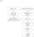
- FIG. 1 is a flowchart diagram illustrating an automated method for generating a prosthesis from a three dimensional ("3D") scan data according to an embodiment of the present invention.
- the automated method for generating the prosthesis from the 3D scan data includes an operation (operation S100) of extracting prep information of a prepared tooth from the 3D scan data, an operation (operation S200) of generating a two dimensional ("2D") projection images by projecting the 3D scan data based on the prep information and an operation (operation S300) of generating the 3D prosthesis based on the 2D projection images using a generative adversarial network including a 2D encoder and a 3D decoder.
- the automated method for generating the prosthesis from the 3D scan data according to the present embodiment may be operated by a computing apparatus.
- FIG. 2 is a detailed flowchart illustrating the automated method for generating the prosthesis from the 3D scan data of FIG. 1 .
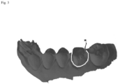
- FIG. 3 is a drawing illustrating a margin line of a prepared tooth of FIG. 2 .
- the automated method for generating the prosthesis from the 3D scan data further includes extracting a margin line ML of the prepared tooth.
- the 3D scan data (a 3D mesh data) of a dental arch including the prepared tooth from a 3D scanner and the margin line ML of the prepared tooth is needed.
- the 3D scan data refers to a scanned data of teeth and oral cavity by a 3D scanner, or a scanned data of an impression object or a reconstructed object of the teeth and the oral cavity by the 3D scanner.
- the 3D scan data may be a mesh data including 3D vertices and triangles or quadrangles generated by connecting the vertices.
- a file extension of the 3D scan data may not be limited.
- the file extension of the 3D scan data may be one of ply, obj and stl.
- the prepared tooth may mean a tooth prepared for a crown.
- the prepared tooth may mean a tooth obtained by cutting a part of the tooth. To generate a single crown, an operation of shaving off a natural tooth to make it easier to place a prosthesis is needed.
- the natural tooth which is shaved off may be referred to the prepared tooth.
- the margin line ML may refer to an edge portion of the prepared tooth.
- the margin line ML may represent a boundary between the prepared tooth and a gum.
- the margin line ML of the prepared tooth is illustrated.
- the margin line ML is automatically extracted from the 3D scan data.
- the margin line MLs may be automatically extracted from the 3D scan data using an artificial intelligence neural network.
- the operation of automatically extracting the margin line ML may include an operation of extracting a partial scan data corresponding to the prepared tooth from the 3D scan data, an operation of mapping the partial scan data into a predetermined 2D space using a transformation matrix T, an operation of obtaining a 2D margin line by determining a curvature value from data mapped into the 2D space and an operation of converting the 2D margin line into a 3D margin line using an inverse matrix of the transformation matrix.
- the curvature value may be one of a maximum curvature value, a minimum curvature value, a Gaussian curvature value and an average curvature value.
- the curvature value may have a relatively constant value.
- the curvature value may greatly change at a boundary between teeth or a boundary between teeth and gums. Accordingly, the margin line of the tooth may be determined using the curvature value.
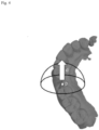
- FIG. 4 is a drawing illustrating an operation (operation S100) of extracting prep information of the prepared tooth of FIG. 1 .
- Prep Info Extractor In order to use the 3D scan data as an input of a deep learning model, an operation (Prep Info Extractor) of extracting the prep information of the prepared tooth from the 3D scan data is necessary.
- the prep information is extracted using a prepared mesh data extracted using the margin line ML.
- the prep information may include a position p of the prepared tooth and a direction d of the prepared tooth.
- the position p of the prepared tooth may be a center of gravity (Prep center) of the prepared mesh data.
- a number of vertices of the prepared mesh data is K
- the position p of the prepared tooth is a center of the margin line ML.
- the direction d of the prepared tooth is determined using normal vectors of surfaces of the prepared mesh data.
- the direction d of the prepared tooth may represent a protruded direction of the prepared tooth.
- the direction d of the prepared tooth may represent a direction (Insertion Direction) in which the prosthesis model is inserted into the prepared tooth.
- x opt is a direction in which a normal vector of a point of the prepared mesh data is not obscured and T is a transpose function switching row and column indices of a matrix
- x T n If the normal vector n in direction x which is not obscured is expressed in a formula, x T n>0.
- an angle between x and n is an acute angle.
- x T n When the angle between x and n is an acute angle, x T n>0.
- x opt may be the direction in which an average value of the angle with the normal vectors on the surfaces of the prepared mesh data is the lowest.
- the 2D projection images may be generated by projecting the 3D scan data based on the position p and the direction d of the prepared tooth.
- the automated method for generating the prosthesis from the 3D scan data may further include aligning the 3D scan data at a origin of a predetermined coordinate system in directions of the predetermined coordinate system prior to the operation (operation S200) of generating the 2D projection images.
- the 3D scan data aligned in this way may be referred to "processed 3D Models".
- the 2D projection images may be defined such that the adjacent tooth of the prepared tooth is visible.
- the 2D projection images may be defined such that the opposite tooth of the prepared tooth and the adjacent tooth of the prepared tooth are visible.
- Pixel values of the 2D projection images may be defined as distances to the closest points hitting the 3D scan data when rays are emitted from the projection planes A d1 , A d2 and A d3 in the directions of the normal vectors d1, d2 and d3 of the projection planes A d1 , A d2 and A d3 .
- the pixel values of the 2D projection images may be defined as perspective views of the 3D scan data when rays are emitted from the projection planes A d1 , A d2 and A d3 in the direction of the normal vectors d1, d2 and d3 of the projection planes A d1 , A d2 and A d3 .
- the present invention may not be limited thereto.
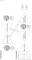
- FIG. 6 is a drawing illustrating a generative adversarial network used in an operation (operation S300) of generating a 3D prosthesis model FIG. 1 .
- the generative adversarial network may be referred to a geometric AI.
- Inputs of the geometric AI may be the 2D projection images, and an output of the geometric AI may be a 3D prosthesis model.
- the 3D prosthesis model may be a 3D single crown model (3D Crown Model).
- the generative adversarial network includes a 2D encoder (Image Encoder) and a 3D decoder (Mesh Decoder).
- the 2D encoder receives the 2D projection images and outputs a latent vector.
- the 3D decoder receives the latent vector and generates coordinates of points forming the 3D prosthesis.
- the 2D encoder may receive M projection image data ( I ⁇ R M ⁇ H ⁇ W ) having a size of H ⁇ W as the inputs and may provide the encoded latent vector as the output.
- the 3D decoder may receive the latent vector generated by the 2D encoder as the input and may generate the 3D output corresponding to a final crown model.
- the data with fixed connections are trained so that the 3D output may only predict the position of each point of the mesh.
- an operation applied to an unstructured data may be used instead of a 2D convolution operation for a structured data.
- the 3D decoder may utilize graph convolution operations such as GCN, ChebConv, GraphConv, PointNetConv, DynamicEdgeConv and SpiralConv.
- the 3D crown mesh may be generated using the 2D projection images.
- the geometric AI may generate the 3D crown mesh by combining the 2D projection images obtained from plural directions.
- the generative advertising network may include the image decoder that understanding the 2D image information and the mesh decoder reinterpreting the information understood in 2D to 3D.
- FIG. 7 is a drawing illustrating a method of generating answer data used for training of the generative adversarial network of FIG. 6 .
- the automated method for generating the prosthesis from the 3D scan data may further include generating a prosthesis answer data used for training the generative adversarial network.
- a first answer data CR1 corresponding to the prepared tooth may be converted into a second answer data CR2 having fixed connections using a deformable registration.
- the second answer data CR2 may be generated by repetitively dividing a cube-shaped initial model M1 into eight same parts and transforming the initial model M1 to be closer to a shape of the first answer data CR1.
- training the geometric AI may be necessary to generate the 3D crown model proposed in the present invention.
- the 3D scan data including the prepared tooth and actual crown mesh data CR1 which are generated by dental technicians and corresponding to the prepared tooth may be needed.
- teeth shapes and positions of feature points are different for each patient and formats of scanned data are not constant so that it may be not proper to use the crown mesh data CR1 generated by the dental technicians for training the geometric AI.
- a method of deformable registration of the crown mesh data CR1 generated by dental technicians to a polygon mesh e.g. a tooth library
- a polygon mesh e.g. a tooth library
- Deformable registration may refer to a method of matching a source mesh having unspecified properties (connection relationships) to the connection relationships of an already defined target mesh.
- the crown mesh data CR1 generated by different dental technicians have different properties (connection relationships). When the deformable registration is used, the properties of the crown mesh data CR1 generated by different dental technicians may become the same.
- a mesh shrink wrapping method may be used as a method of the deformable registration.
- a mesh having a target shape CR1 may be generated by dividing a quad mesh of a cube through several steps.
- the crown mesh data CR2 with the same properties may be used as the answer data for training the geometric AI.
- intermediate data such as M2, M3, M4 and M5 may be generated.
- the second answer data CR2 may be generated, which has the same form as the first answer data CR1 and has the fixed connections.
- FIG. 8 is a drawing illustrating a method of training the generative adversarial network of FIG. 6 .
- the automated method for generating the prosthesis from the 3D scan data may further include training the generative adversarial network.
- the operation of training the generative adversarial network may include a first training stage (Training Stage 1) in which the prosthesis answer data (e.g. CR2 in FIG. 7 ) is inputted to the 3D encoder (Mesh Encoder) to generate a latent vector Z and the latent vector Z is inputted to the 3D decoder (Mesh Decoder) to restore the prosthesis answer data (e.g. CR2 in FIG. 7 ).
- the prosthesis answer data may be the second answer data CR2.
- the operation of training the generative adversarial network may further include a second training stage (Training Stage 2) in which a training 3D prosthesis is generated by a generator and whether the training 3D prosthesis is true or fake is determined by a discriminator.
- a second training stage Training Stage 2 in which a training 3D prosthesis is generated by a generator and whether the training 3D prosthesis is true or fake is determined by a discriminator.
- the generator may include the 2D encoder (Image Encoder) and the 3D decoder (Pretrained Mesh Decoder) trained in the first training stage (Training Stage 1).
- the discriminator may include the 3D encoder (Pretrained Mesh Encoder) trained in the first training stage (Training Stage 1).
- the generative adversarial network may include two model generators and two discriminators.
- the generative advocacy network uses the following optimization method to generate better results.
- connection relationships of the data are fixed so that the points p gt 1 ⁇ p gt X of the answer mesh data and the points p pred 1 ⁇ p pred X of the mesh data predicted by the deep learning model may have a one-to-one correspondence.
- a highly complex loss such as chamfer loss as the training objective function.
- the deep learning model according to the present invention may be trained using L 1 L 2 loss which is relatively simple.
- the 3D coordinates of the prosthesis may be directly generated so that the automated method may be applied to an anterior region where it is difficult to reconstruct the 2D coordinates to the 3D coordinates due to lack of the occlusion information.
- the computer readable medium may include a magnetic medium such as a hard disk, a floppy disk and a magnetic tape, an optical recording medium such as CD-ROM and DVD, a magneto-optical medium such as floptic disc and a hardware device specially configured to store and execute the program instructions such as ROM, RAM and a flash memory.
- the program instructions may include a machine language codes produced by a compiler and high-level language codes which may be executed by a computer using an interpreter or the like.
- the hardware device may be configured to operate as one or more software modules to perform the operations of the present invention.
- the above mentioned automated method for generating the prosthesis from the 3D scan data may be implemented in a form of a computer-executed computer program or an application which are stored in a storage method.
Landscapes
- Health & Medical Sciences (AREA)
- Engineering & Computer Science (AREA)
- Physics & Mathematics (AREA)
- General Health & Medical Sciences (AREA)
- Theoretical Computer Science (AREA)
- General Physics & Mathematics (AREA)
- Life Sciences & Earth Sciences (AREA)
- Oral & Maxillofacial Surgery (AREA)
- Veterinary Medicine (AREA)
- Public Health (AREA)
- Animal Behavior & Ethology (AREA)
- Epidemiology (AREA)
- Dentistry (AREA)
- Computer Vision & Pattern Recognition (AREA)
- Quality & Reliability (AREA)
- Optics & Photonics (AREA)
- Software Systems (AREA)
- Radiology & Medical Imaging (AREA)
- Computer Graphics (AREA)
- Nuclear Medicine, Radiotherapy & Molecular Imaging (AREA)
- Medical Informatics (AREA)
- Geometry (AREA)
- Processing Or Creating Images (AREA)
- Image Analysis (AREA)
- Dental Tools And Instruments Or Auxiliary Dental Instruments (AREA)
- Image Processing (AREA)
- Apparatus For Radiation Diagnosis (AREA)
Description
- This application claims the priority of
Korean Patent Application No. 10-2022-0152907, filed on November 15, 2022 PCT/KR2022/018637 filed on November 23, 2022 - Embodiments relate to an automated method for generating a prosthesis from a three dimensional ("3D") scan data, a generator generating the prosthesis from the 3D scan data and a non-transitory computer-readable storage medium having stored thereon program instructions of the automated method for generating the prosthesis. More particularly, embodiments relate to an automated method for generating a prosthesis from a 3D scan data reducing a time for generating the prosthesis by using a geometric deep learning, a generator generating the prosthesis from the 3D scan data and a non-transitory computer-readable storage medium having stored thereon program instructions of the automated method for generating the prosthesis.
- A three dimensional ("3D") oral scan data refers to a scanned data of teeth and oral cavity by a 3D scanner, or a scanned data of an impression object or a reconstructed object of the teeth and the oral cavity by the 3D scanner. In prosthetic treatment such as in-ray, on-ray, and crown, dental treatment such as implant and orthodontic treatment, oral data of the patient may be acquired and be used to design prosthesis or implant, braces.
- Conventionally, a method of generating a prosthesis manually after taking a direct model of the teeth and the oral cavity using alginate or the like has been mainly used. In order to make an anatomically correct prosthesis, a dentist or a dental technician may determine a degree of wear on adjacent teeth, a tooth number and occlusion information of an antagonist tooth, and then generate the prosthesis. In the conventional prosthesis generating method, an operator may manually modify a general tooth shape according to the oral condition of each patient in consideration of the above information.
- Conventionally, the prosthesis may be generated manually, work fatigue of the dentist or the dental technician may increase and accuracy and productivity of the prosthesis may decrease. In addition, the quality of the prosthesis and the time for generating the prosthesis may vary greatly depending on the proficiency of the operator.
- Document
US 2021 / 0 153 986 A1 discloses a method, system and computer readable storage media for obtaining 3D dental restoration geometries from 2D dental designs. The method includes obtaining a training dataset, training the neural network using the training dataset, taking a scan of a patient, such as a 3D measurement of a patient's oral cavity, obtaining a 2D dental design, producing a 3D dental restoration geometry using the obtained 2D dental design and the trained neural network. - Document
US 2021 / 0 059 796 A1 discloses an automated detection, generation and/or correction of dental features in digital models. A 3D model of a dental site is generated from intraoral scan data of the dental site, wherein the 3D model comprises a representation of a preparation tooth. An image of the preparation tooth is received or generated, wherein the image comprises a height map. Data from the image is processed using a trained machine learning model that has been trained to identify margin lines of preparation teeth, wherein the trained machine learning model outputs a probability map comprising, for each pixel in the image, a probability that the pixel depicts a margin line. The 3D model of the dental site is then updated by marking the margin line on the representation of the preparation tooth based on the probability map. - Document
EP 4 331 531 A1 discloses an automated method for generating a prosthesis from a 3D scan data. The method includes automatically extracting tooth information of a tooth included in the 3D scan data from the 3D scan data, automatically extracting a margin line of a prepared tooth, and generating a plurality of 2D images including the prepared tooth and an adjacent tooth adjacent to the prepared tooth. The method further includes automatically generating a 3D temporary prosthesis data based on the plurality of 2D images and deforming a single tooth model corresponding to the prepared tooth using the margin line and the 3D temporary prosthesis data to generate a 3D prostheses data. - Document
US 2019 / 0 282 344 A1 discloses a computer implemented method for generating a 3D dental prosthesis model. The method includes training a deep neural network to generate a first 3D dental prosthesis model using a training data set, receiving a patient scan data representing at least a portion of a patient's dentition, and generating, using the trained deep neural network, the first 3D dental prosthesis model based on the received patient scan data. - The invention is as defined in the appended claims.
- It is an object of the present invention to provide an automated method for generating a prosthesis from a three dimensional ("3D") scan data reducing a time for generating the prosthesis by using a geometric deep learning.
- It is an object of the present invention to provide a generator generating a prosthesis from a 3D scan data.
- It is an object of the present invention to provide a non-transitory computer-readable storage medium having stored thereon program instructions of the automated method for generating a prosthesis from a 3D scan data.
- To this end, the present invention provides an automated method for generating a prosthesis from a 3D scan data in accordance with
claim 1, a generator for generating a prosthesis from a 3D scan data in accordance with claim 16, and a non-transitory computer-readable storage medium having stored thereon program instruction in accordance with claim 17. According to the present invention, the method includes extracting prep information of a prepared tooth from the 3D scan data, generating a two dimensional ("2D") projection images by projecting the 3D scan data based on the prep information and generating a 3D prosthesis based on the 2D projection images using a generative adversarial network including a 2D encoder and a 3D decoder. - In the present invention, the method further includes extracting a margin line of the prepared tooth. The prep information is extracted using a prepared mesh data extracted using the margin line.
- In an embodiment, the prep information may include a position of the prepared tooth. The position of the prepared tooth may be a center of gravity of the prepared mesh data.
- In an embodiment, the prep information may include a position of the prepared tooth. The position of the prepared tooth may be a center of the margin line.
- In the present invention, the prep information includes a direction of the prepared tooth. The direction of the prepared tooth is determined using normal vectors of surfaces of the prepared mesh data.
- In an embodiment, when the direction of the prepared tooth is d, a number of the surfaces of the prepared mesh data is N, the normal vectors are {n 1, ··· , nN }, xopt is a direction in which a normal vector of a point of the prepared mesh data is not obscured and T is a transpose function switching row and column indices of a matrix,

- In an embodiment, the prep information may include a position of the prepared tooth and a direction of the prepared tooth. The 2D projection images may be generated using projection planes. The projection planes may be spaced apart from a predetermined distance from the position of the prepared tooth and defined such that an opposite tooth of the prepared tooth or an adjacent tooth of the prepared tooth is visible.
- In an embodiment, pixel values of the 2D projection images may be defined as distances to the closest points hitting the 3D scan data when rays are emitted from the projection planes in directions of normal vectors of the projection planes.
- In an embodiment, the 2D encoder may be configured to receive the 2D projection images and to output a latent vector.
- In an embodiment, the 3D decoder may be configured to receive the latent vector and to generate coordinates of points forming the 3D prosthesis.
- In an embodiment, the method may further include generating a prosthesis answer data used for training the generative adversarial network. The generating a prosthesis answer data may include converting a first answer data corresponding to the prepared tooth into a second answer data having fixed connections using a deformable registration.
- In an embodiment, the generating a prosthesis answer data may include dividing a cube-shaped initial model into eight parts and transforming the initial model to be closer to a shape of the first answer data to generate the second answer data.
- In an embodiment, the method may further include training the generative adversarial network. The training the generative adversarial network may include a first training stage in which a prosthesis answer data is inputted to a 3D encoder to generate a latent vector and the latent vector is inputted to the 3D decoder to restore the prosthesis answer data.
- In an embodiment, the training the generative adversarial network may further include a second training stage in which a
training 3D prosthesis is generated by a generator and whether thetraining 3D prosthesis is true or fake is determined by a discriminator. - In an embodiment, the generator may include the 2D encoder and the 3D decoder which is trained in the first training stage. The discriminator may include the 3D encoder in the first training stage.
- In an embodiment, a loss representing a distance difference between points of an answer mesh data and points of a predicted mesh data may be used as a training objective function. A number of the points of the answer mesh data may be equal to a number of the points of the predicted mesh data. When the loss is L, the number of the points of the answer mesh data is X, the points of the answer mesh data are


- In an embodiment, a first answer data corresponding to the prepared tooth may be converted into a second answer data having fixed connections using a deformable registration. The prosthesis answer data may be the second answer data.
- A generator for generating a prosthesis from a 3D scan data, according to the present invention, includes a 2D encoder configured to receive 2D projection images of a prepared tooth of the 3D scan data and to output a latent vector and a 3D decoder configured to receive the latent vector and to generate coordinates of points forming a 3D prosthesis for the prepared tooth.
- In a non-transitory computer-readable storage medium having stored thereon program instructions according to the present invention, the program instructions are executable by at least one hardware processor to extract prep information of a prepared tooth from a three dimensional ("3D") scan data, generate a two dimensional ("2D") projection images by projecting the 3D scan data based on the prep information and generate a 3D prosthesis based on the 2D projection images using a generative adversarial network including a 2D encoder and a 3D decoder.
- According to the automated method for generating the prosthesis from the 3D scan data, the prep information of the prepared tooth may be automatically extracted, the 2D projection images, which are the projection images of the 3D scan data based on the prep information, may be generated and the 3D prosthesis may be automatically generated using the generative adversarial network including the 2D encoder and the 3D decoder.
- In the automated method for generating the prosthesis from the 3D scan data of the present invention, instead of generating the 2D coordinates of the prosthesis and reconstructing the 3D coordinates using the 2D coordinates, the 3D coordinates of the prosthesis may be directly generated using the generative adversarial network so that the complex post-processing to reconstruct the 2D coordinates to the 3D coordinates may not be needed.
- In addition, in the automated method for generating the prosthesis from the 3D scan data of the present invention, the 3D coordinates of the prosthesis may be directly generated so that the automated method may be applied to an anterior region where it is difficult to reconstruct the 2D coordinates to the 3D coordinates due to lack of the occlusion information.
- In this way, the prosthesis may be automatically generated from the 3D scan data, so that the time and processes of generating the prosthesis may be reduced, and the quality of the prosthesis may be enhanced.
- The above and other features and advantages of the present invention will become more apparent by describing in detailed embodiments thereof with reference to the accompanying drawings, in which:
-
FIG. 1 is a flowchart diagram illustrating an automated method for generating a prosthesis from a three dimensional ("3D") scan data according to an embodiment of the present invention; -
FIG. 2 is a detailed flowchart illustrating the automated method for generating the prosthesis from the 3D scan data ofFIG. 1 ; -
FIG. 3 is a drawing illustrating a margin line of a prepared tooth ofFIG. 2 ; -
FIG. 4 is a drawing illustrating an operation of extracting prep information of the prepared tooth ofFIG. 1 ; -
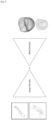
FIG. 5 is a drawing illustrating an operation of generating two dimensional ("2D") projection images ofFIG. 1 ; -
FIG. 6 is a drawing illustrating a generative adversarial network used in an operation of generating a 3D prosthesis modelFIG. 1 ; -
FIG. 7 is a drawing illustrating a method of generating answer data used for training of the generative adversarial network ofFIG. 6 ; and -
FIG. 8 is a drawing illustrating a method of training the generative adversarial network ofFIG. 6 . - The present invention now will be described more fully hereinafter with reference to the accompanying drawings, in which embodiments of the present invention are shown. The present invention may, however, be embodied in many different forms and should not be construed as limited to the embodiments set forth herein.
- Rather, these embodiments are provided so that this disclosure will be thorough and complete, and will fully convey the scope of the present invention to those skilled in the art. Like reference numerals refer to like elements throughout.
- It will be understood that, although the terms first, second, third, etc. may be used herein to describe various elements, components, regions, layers and/or sections, these elements, components, regions, layers and/or sections should not be limited by these terms. These terms are only used to distinguish one element, component, region, layer or section from another region, layer or section. Thus, a first element, component, region, layer or section discussed below could be termed a second element, component, region, layer or section without departing from the teachings of the present invention.
- The terminology used herein is for the purpose of describing particular embodiments only and is not intended to be limiting of the present invention. As used herein, the singular forms "a," "an" and "the" are intended to include the plural forms as well, unless the context clearly indicates otherwise. It will be further understood that the terms "comprises" and/or "comprising," when used in this specification, specify the presence of stated features, integers, steps, operations, elements, and/or components, but do not preclude the presence or addition of one or more other features, integers, steps, operations, elements, components, and/or groups thereof.
- Unless otherwise defined, all terms (including technical and scientific terms) used herein have the same meaning as commonly understood by one of ordinary skill in the art to which this invention belongs. It will be further understood that terms, such as those defined in commonly used dictionaries, should be interpreted as having a meaning that is consistent with their meaning in the context of the relevant art and will not be interpreted in an idealized or overly formal sense unless expressly so defined herein.
- All methods described herein can be performed in a suitable order unless otherwise indicated herein or otherwise clearly contradicted by context. The use of any and all examples, or exemplary language (e.g., "such as"), is intended merely to better illustrate the invention and does not pose a limitation on the scope of the invention unless otherwise claimed. No language in the specification should be construed as indicating any non-claimed element as essential to the practice of the present invention as used herein.
- Hereinafter, the present invention will be explained in detail with reference to the accompanying drawings.
-
FIG. 1 is a flowchart diagram illustrating an automated method for generating a prosthesis from a three dimensional ("3D") scan data according to an embodiment of the present invention. - Referring to
FIG. 1 , the automated method for generating the prosthesis from the 3D scan data according to the present embodiment includes an operation (operation S100) of extracting prep information of a prepared tooth from the 3D scan data, an operation (operation S200) of generating a two dimensional ("2D") projection images by projecting the 3D scan data based on the prep information and an operation (operation S300) of generating the 3D prosthesis based on the 2D projection images using a generative adversarial network including a 2D encoder and a 3D decoder. - The automated method for generating the prosthesis from the 3D scan data according to the present embodiment may be operated by a computing apparatus.
-
FIG. 2 is a detailed flowchart illustrating the automated method for generating the prosthesis from the 3D scan data ofFIG. 1 .FIG. 3 is a drawing illustrating a margin line of a prepared tooth ofFIG. 2 . - Referring to
FIGS. 1 to 3 , the automated method for generating the prosthesis from the 3D scan data further includes extracting a margin line ML of the prepared tooth. - In order to use the present invention, the 3D scan data (a 3D mesh data) of a dental arch including the prepared tooth from a 3D scanner and the margin line ML of the prepared tooth is needed.
- Herein, the 3D scan data refers to a scanned data of teeth and oral cavity by a 3D scanner, or a scanned data of an impression object or a reconstructed object of the teeth and the oral cavity by the 3D scanner. For example, the 3D scan data may be a mesh data including 3D vertices and triangles or quadrangles generated by connecting the vertices. A file extension of the 3D scan data may not be limited. For example, the file extension of the 3D scan data may be one of ply, obj and stl.
- Herein, the prepared tooth may mean a tooth prepared for a crown. The prepared tooth may mean a tooth obtained by cutting a part of the tooth. To generate a single crown, an operation of shaving off a natural tooth to make it easier to place a prosthesis is needed. The natural tooth which is shaved off may be referred to the prepared tooth. The margin line ML may refer to an edge portion of the prepared tooth. The margin line ML may represent a boundary between the prepared tooth and a gum.
- In
FIG. 3 , the margin line ML of the prepared tooth is illustrated. For example, the margin line ML is automatically extracted from the 3D scan data. For example, the margin line MLs may be automatically extracted from the 3D scan data using an artificial intelligence neural network. - For example, the operation of automatically extracting the margin line ML may include an operation of extracting a partial scan data corresponding to the prepared tooth from the 3D scan data, an operation of mapping the partial scan data into a predetermined 2D space using a transformation matrix T, an operation of obtaining a 2D margin line by determining a curvature value from data mapped into the 2D space and an operation of converting the 2D margin line into a 3D margin line using an inverse matrix of the transformation matrix.
- For example, the curvature value may be one of a maximum curvature value, a minimum curvature value, a Gaussian curvature value and an average curvature value.
- In an upper surface of the tooth, the curvature value may have a relatively constant value. On the other hand, the curvature value may greatly change at a boundary between teeth or a boundary between teeth and gums. Accordingly, the margin line of the tooth may be determined using the curvature value.
-
FIG. 4 is a drawing illustrating an operation (operation S100) of extracting prep information of the prepared tooth ofFIG. 1 . - Referring to
FIGS. 1 to 4 , in order to use the 3D scan data as an input of a deep learning model, an operation (Prep Info Extractor) of extracting the prep information of the prepared tooth from the 3D scan data is necessary. - For example, in the operation (operation S100) of extracting the prep information, the prep information is extracted using a prepared mesh data extracted using the margin line ML.
- For example, the prep information may include a position p of the prepared tooth and a direction d of the prepared tooth. For example, the position p of the prepared tooth may be a center of gravity (Prep center) of the prepared mesh data.
- For example, when the position of the prepared tooth is p, a number of vertices of the prepared mesh data is K, the vertices are {q 1, ··· , qK },

- Alternatively, the position p of the prepared tooth is a center of the margin line ML.
- The direction d of the prepared tooth is determined using normal vectors of surfaces of the prepared mesh data. The direction d of the prepared tooth may represent a protruded direction of the prepared tooth. The direction d of the prepared tooth may represent a direction (Insertion Direction) in which the prosthesis model is inserted into the prepared tooth.
- For example, when the direction of the prepared tooth is d, a number of surfaces of the prepared mesh data is N, the normal vectors are {n 1, ··· , nN }, xopt is a direction in which a normal vector of a point of the prepared mesh data is not obscured and T is a transpose function switching row and column indices of a matrix,

- If the normal vector n in direction x which is not obscured is expressed in a formula, xTn>0. Herein, an angle between x and n is an acute angle. When the angle between x and n is an acute angle, xTn>0. In contrast, when the angle between x and n is an obtuse angle, xTn<0. Therefore, xopt may be the direction in which an average value of the angle with the normal vectors on the surfaces of the prepared mesh data is the lowest.
-
FIG. 5 is a drawing illustrating an operation (operation S200) of generating two dimensional ("2D") projection images ofFIG. 1 . - Referring to
FIGS. 1 to 5 , the 2D projection images (Projected Images) may be generated by projecting the 3D scan data based on the position p and the direction d of the prepared tooth. - The automated method for generating the prosthesis from the 3D scan data may further include aligning the 3D scan data at a origin of a predetermined coordinate system in directions of the predetermined coordinate system prior to the operation (operation S200) of generating the 2D projection images. The 3D scan data aligned in this way may be referred to "processed 3D Models".
- The 2D projection images may be generated using projection planes Ad1, Ad2 and Ad3. The projection planes Ad1, Ad2 and Ad3 may be spaced apart from a predetermined distance from the position p of the prepared tooth and may be defined such that an opposite tooth of the prepared tooth or an adjacent tooth of the prepared tooth is visible.
- For example, when the 3D scan data includes only one of a maxilla data and a mandible data, the 2D projection images may be defined such that the adjacent tooth of the prepared tooth is visible.
- For example, when the 3D scan data includes a maxilla data and a mandible data as a pair, the 2D projection images may be defined such that the opposite tooth of the prepared tooth and the adjacent tooth of the prepared tooth are visible.
- Pixel values of the 2D projection images may be defined as distances to the closest points hitting the 3D scan data when rays are emitted from the projection planes Ad1, Ad2 and Ad3 in the directions of the normal vectors d1, d2 and d3 of the projection planes Ad1, Ad2 and Ad3. Alternatively, the pixel values of the 2D projection images may be defined as perspective views of the 3D scan data when rays are emitted from the projection planes Ad1, Ad2 and Ad3 in the direction of the normal vectors d1, d2 and d3 of the projection planes Ad1, Ad2 and Ad3.
- Although the number of the 2D projection images is three in
FIG. 5 , the present invention may not be limited thereto. -
FIG. 6 is a drawing illustrating a generative adversarial network used in an operation (operation S300) of generating a 3D prosthesis modelFIG. 1 . - Referring to
FIGS. 1 to 6 , the generative adversarial network may be referred to a geometric AI. - Inputs of the geometric AI may be the 2D projection images, and an output of the geometric AI may be a 3D prosthesis model. Herein, the 3D prosthesis model may be a 3D single crown model (3D Crown Model).
- The generative adversarial network includes a 2D encoder (Image Encoder) and a 3D decoder (Mesh Decoder). The 2D encoder receives the 2D projection images and outputs a latent vector. The 3D decoder receives the latent vector and generates coordinates of points forming the 3D prosthesis.
- For example, the 2D encoder may receive M projection image data (I ∈ R M×H×W ) having a size of H × W as the inputs and may provide the encoded latent vector as the output.
- For example, the 3D decoder may receive the latent vector generated by the 2D encoder as the input and may generate the 3D output corresponding to a final crown model.
- In the present invention, the data with fixed connections are trained so that the 3D output may only predict the position of each point of the mesh. To predict the position of each point of the mesh, an operation applied to an unstructured data may be used instead of a 2D convolution operation for a structured data. For example, the 3D decoder may utilize graph convolution operations such as GCN, ChebConv, GraphConv, PointNetConv, DynamicEdgeConv and SpiralConv.
- As shown in
FIG. 5 , the 3D crown mesh may be generated using the 2D projection images. The geometric AI may generate the 3D crown mesh by combining the 2D projection images obtained from plural directions. The generative advertising network may include the image decoder that understanding the 2D image information and the mesh decoder reinterpreting the information understood in 2D to 3D. -
FIG. 7 is a drawing illustrating a method of generating answer data used for training of the generative adversarial network ofFIG. 6 . - Referring to
FIGS. 1 to 7 , the automated method for generating the prosthesis from the 3D scan data may further include generating a prosthesis answer data used for training the generative adversarial network. In the operation of generating the prosthesis answer data, a first answer data CR1 corresponding to the prepared tooth may be converted into a second answer data CR2 having fixed connections using a deformable registration. - For example, in the operation of generating the prosthesis answer data, the second answer data CR2 may be generated by repetitively dividing a cube-shaped initial model M1 into eight same parts and transforming the initial model M1 to be closer to a shape of the first answer data CR1.
- Specifically, training the geometric AI may be necessary to generate the 3D crown model proposed in the present invention. For training the geometric AI, the 3D scan data including the prepared tooth and actual crown mesh data CR1 which are generated by dental technicians and corresponding to the prepared tooth may be needed. However, teeth shapes and positions of feature points are different for each patient and formats of scanned data are not constant so that it may be not proper to use the crown mesh data CR1 generated by the dental technicians for training the geometric AI.
- As a solution to this, a method of deformable registration of the crown mesh data CR1 generated by dental technicians to a polygon mesh (e.g. a tooth library) representing a shape of a typical tooth, a cubic initial model or a spherical initial model may be used. Deformable registration may refer to a method of matching a source mesh having unspecified properties (connection relationships) to the connection relationships of an already defined target mesh.
- The crown mesh data CR1 generated by different dental technicians have different properties (connection relationships). When the deformable registration is used, the properties of the crown mesh data CR1 generated by different dental technicians may become the same.
- As shown in
FIG. 6 , as a method of the deformable registration, a mesh shrink wrapping method may be used. In the mesh shrink wrapping method, a mesh having a target shape CR1 may be generated by dividing a quad mesh of a cube through several steps. The crown mesh data CR2 with the same properties may be used as the answer data for training the geometric AI. - For example, by applying a step by step algorithm to the cubic initial mesh M1 through the mesh shrink wrapping method of
FIG. 6 , intermediate data such as M2, M3, M4 and M5 may be generated. Finally, the second answer data CR2 may be generated, which has the same form as the first answer data CR1 and has the fixed connections. -
FIG. 8 is a drawing illustrating a method of training the generative adversarial network ofFIG. 6 . - Referring to
FIGS. 1 to 8 , the automated method for generating the prosthesis from the 3D scan data may further include training the generative adversarial network. - The operation of training the generative adversarial network may include a first training stage (Training Stage 1) in which the prosthesis answer data (e.g. CR2 in
FIG. 7 ) is inputted to the 3D encoder (Mesh Encoder) to generate a latent vector Z and the latent vector Z is inputted to the 3D decoder (Mesh Decoder) to restore the prosthesis answer data (e.g. CR2 inFIG. 7 ). Herein, the prosthesis answer data may be the second answer data CR2. - For example, the operation of training the generative adversarial network may further include a second training stage (Training Stage 2) in which a
training 3D prosthesis is generated by a generator and whether thetraining 3D prosthesis is true or fake is determined by a discriminator. - For example, the generator may include the 2D encoder (Image Encoder) and the 3D decoder (Pretrained Mesh Decoder) trained in the first training stage (Training Stage 1). For example, the discriminator may include the 3D encoder (Pretrained Mesh Encoder) trained in the first training stage (Training Stage 1).
- In the operation of training the generative adversarial network, a loss representing a distance difference between points of an answer mesh data and points of a predicted mesh data may be used as a training objective function. A number of the points of the answer mesh data may be equal to a number of the points of the predicted mesh data. When the loss is L, the number of the points of the answer mesh data is X, the points of the answer mesh data are



- Specifically, the generative adversarial network may include two model generators and two discriminators. The generative advocacy network uses the following optimization method to generate better results.
- The connection relationships of the data are fixed so that the
points 
points 
- The training operation may include two stages. In the first training stage (Training Stage 1), first, the mesh decoder may be trained to express the 3D prosthesis data from the latent vector Z. In this stage, a training method of an auto encoder may be used. Processes of inputting the answer data CR2 as an input to the mesh encoder, compressing the size of the answer data CR2 into the vector Z in a latent space and expanding the latent vector Z to restore the answer data CR2 may be repeated. This may allow the mesh encoder and the mesh decoder to understand the fixed connection relationships.
- In the second training stage (Training Stage 2), a structure model of the generative adversarial network (GAN) may be trained. The generator may include the image encoder extracting the feature vector from the 2D image and the mesh decoder which is pretrained in the first training stage (Training Stage 1). The discriminator may include the mesh encoder which is pretrained in the first training stage (Training Stage 1). When the generator generates the 3D prosthesis data using the 2D projection images, the discriminator determines how the 3D prosthesis data is realistic and provides the determined information to the generator, so that the generator may be trained. The generator trained in this way may generate the 3D prosthesis usable through a simple post-processing without any additional complex algorithms.
- According to the present embodiment, the prep information of the prepared tooth is automatically extracted, the 2D projection images, which are the projection images of the 3D scan data based on the prep information, is generated and the 3D prosthesis is automatically generated using the generative adversarial network including the 2D encoder and the 3D decoder.
- In the automated method for generating the prosthesis from the 3D scan data of the present invention, instead of generating the 2D coordinates of the prosthesis and reconstructing the 3D coordinates using the 2D coordinates, the 3D coordinates of the prosthesis may be directly generated using the generative adversarial network so that the complex post-processing to reconstruct the 2D coordinates to the 3D coordinates may not be needed.
- In addition, in the automated method for generating the prosthesis from the 3D scan data of the present invention, the 3D coordinates of the prosthesis may be directly generated so that the automated method may be applied to an anterior region where it is difficult to reconstruct the 2D coordinates to the 3D coordinates due to lack of the occlusion information.
- In this way, the prosthesis may be automatically generated from the 3D scan data, so that the time and processes of generating the prosthesis may be reduced, and the quality of the prosthesis may be enhanced.
- According to the present invention, a non-transitory computer-readable storage medium having stored thereon program instructions of the automated method for generating the prosthesis from the 3D scan data is provided. The above mentioned method may be written as a program executed on the computer. The method may be implemented in a general purpose digital computer which operates the program using a computer-readable medium. In addition, the structure of the data used in the above mentioned method may be written on a computer readable medium through various means. The computer readable medium may include program instructions, data files and data structures alone or in combination. The program instructions written on the medium may be specially designed and configured for the present invention, or may be generally known to a person skilled in the computer software field. For example, the computer readable medium may include a magnetic medium such as a hard disk, a floppy disk and a magnetic tape, an optical recording medium such as CD-ROM and DVD, a magneto-optical medium such as floptic disc and a hardware device specially configured to store and execute the program instructions such as ROM, RAM and a flash memory. For example, the program instructions may include a machine language codes produced by a compiler and high-level language codes which may be executed by a computer using an interpreter or the like. The hardware device may be configured to operate as one or more software modules to perform the operations of the present invention.
- In addition, the above mentioned automated method for generating the prosthesis from the 3D scan data may be implemented in a form of a computer-executed computer program or an application which are stored in a storage method.
- The present invention is related to the automated method for generating the prosthesis from the 3D scan data and the non-transitory computer-readable storage medium having stored thereon program instructions of the automated method for generating the prosthesis from the 3D scan data. According to the present invention, the time and the effort for generating the prosthesis may be reduced and the accuracy and the productivity of the prosthesis may be enhanced.
- The foregoing is illustrative of the present invention and is not to be construed as limiting thereof. Although a few embodiments of the present invention have been described, those skilled in the art will readily appreciate that many modifications are possible in the embodiments. Therefore, it is to be understood that the foregoing is illustrative of the present invention and is not to be construed as limited to the specific embodiments disclosed. The present invention is defined by the following claims.
Claims (17)
- An automated method for generating a prosthesis from a three dimensional ,"3D", scan data, wherein the 3D scan data is scan data of a dental arch including a prepared tooth, the method comprising:extracting a margin line of the prepared tooth from the 3D scan data;extracting prep information (S100) of the prepared tooth from the 3D scan data, wherein the prep information is extracted using a prepared mesh data extracted using the margin line, wherein the prep information includes a direction of the prepared tooth, and wherein the direction of the prepared tooth is determined using normal vectors of surfaces of the prepared mesh data;generating two dimensional ,"2D", projection images (S200) by projecting the 3D scan data based on the prep information; andgenerating a 3D prosthesis (S300) based on the 2D projection images using a generative adversarial network including a 2D encoder and a 3D decoder.
- The method of claim 1, wherein the prep information includes a position of the prepared tooth, and
wherein the position of the prepared tooth is a center of gravity of the prepared mesh data. - The method of claim 1, wherein the prep information includes a position of the prepared tooth, and
wherein the position of the prepared tooth is a center of the margin line. - The method of claim 1, wherein when the direction of the prepared tooth is d, a number of the surfaces of the prepared mesh data is N, the normal vectors are {n 1, ··· , nN }, xopt is a direction in which a normal vector of a point of the prepared mesh data is not obscured and T is a transpose function switching row and column indices of a matrix,

- The method of claim 1, wherein the prep information includes a position of the prepared tooth and a direction of the prepared tooth,wherein the 2D projection images are generated using projection planes, andwherein the projection planes are spaced apart from a predetermined distance from the position of the prepared tooth and defined such that an opposite tooth of the prepared tooth or an adjacent tooth of the prepared tooth is visible.
- The method of claim 5, wherein pixel values of the 2D projection images are defined as distances to the closest points hitting the 3D scan data when rays are emitted from the projection planes in directions of normal vectors of the projection planes.
- The method of claim 1, wherein the 2D encoder is configured to receive the 2D projection images and to output a latent vector.
- The method of claim 7, wherein the 3D decoder is configured to receive the latent vector and to generate coordinates of points forming the 3D prosthesis.
- The method of claim 1, further comprising:generating a prosthesis answer data used for training the generative adversarial network,wherein the generating a prosthesis answer data comprises:
converting a first answer data corresponding to the prepared tooth into a second answer data having fixed connections using a deformable registration. - The method of claim 9, wherein the generating a prosthesis answer data comprises:
dividing a cube-shaped initial model into eight parts and transforming the initial model to be closer to a shape of the first answer data to generate the second answer data. - The method of claim 1, further comprising:training the generative adversarial network,wherein training the generative adversarial network comprises:
a first training stage in which a prosthesis answer data is inputted to a 3D encoder to generate a latent vector and the latent vector is inputted to the 3D decoder to restore the prosthesis answer data. - The method of claim 11, wherein training the generative adversarial network further comprises:
a second training stage in which a training 3D prosthesis is generated by a generator and whether the training 3D prosthesis is true or fake is determined by a discriminator. - The method of claim 12, wherein the generator comprises the 2D encoder and the 3D decoder which is trained in the first training stage, and
wherein the discriminator comprises the 3D encoder in the first training stage. - The method of claim 12, wherein a loss representing a distance difference between points of an answer mesh data and points of a predicted mesh data is used as a training objective function,wherein a number of the points of the answer mesh data is equal to a number of the points of the predicted mesh data, andwherein when the loss is L, the number of the points of the answer mesh data is X, the points of the answer mesh data are


- The method of claim 11, wherein a first answer data corresponding to the prepared tooth is converted into a second answer data having fixed connections using a deformable registration, and
wherein the prosthesis answer data is the second answer data. - A generator for generating a prosthesis from a three dimensional ,"3D", scan data, wherein the 3D scan data is a scan data of dental arch including a prepared tooth, the generator comprising:a two dimensional ,"2D", encoder configured to receive 2D projection images of the prepared tooth of the 3D scan data and to output a latent vector; anda 3D decoder configured to receive the latent vector and to generate coordinates of points forming a 3D prosthesis for the prepared tooth,wherein the 2D projection images are generated by projecting the 3D scan data based on a prep information,wherein the prep information is extracted from the 3D scan data using a prepared mesh data extracted using a margin line of the prepared tooth,wherein the prep information includes a direction of the prepared tooth, andwherein the direction of the prepared tooth is determined using normal vectors of surfaces of the prepared mesh data.
- A non-transitory computer-readable storage medium having stored thereon program instructions, the program instructions executable by at least one hardware processor to:extract a margin line of a prepared tooth from a three dimensional, 3D, scan data, wherein the 3D scan data is a scan data of dental arch including a prepared tooth;extract prep information of a prepared tooth from the 3D scan data, wherein the prep information is extracted using a prepared mesh data extracted using the margin line, wherein the prep information includes a direction of the prepared tooth, and wherein the direction of the prepared tooth is determined using normal vectors of surfaces of the prepared mesh data;generate a two dimensional ,"2D", projection images by projecting the 3D scan data based on the prep information; andgenerate a 3D prosthesis based on the 2D projection images using a generative adversarial network including a 2D encoder and a 3D decoder.
Applications Claiming Priority (2)
| Application Number | Priority Date | Filing Date | Title |
|---|---|---|---|
| KR1020220152907A KR102610682B1 (en) | 2022-11-15 | 2022-11-15 | Automated method for generating prosthesis from three dimensional scan data, generator generating prosthesis from three dimensional scan data and computer readable medium having program for performing the method |
| PCT/KR2022/018637 WO2024106583A1 (en) | 2022-11-15 | 2022-11-23 | Method for automatically generating prosthesis from three-dimensional scan data, generator for automatically generating prosthesis from three-dimensional scan data, and computer-readable recording medium on which program for executing same in computer is recorded |
Publications (3)
| Publication Number | Publication Date |
|---|---|
| EP4371527A1 EP4371527A1 (en) | 2024-05-22 |
| EP4371527B1 true EP4371527B1 (en) | 2025-07-02 |
| EP4371527C0 EP4371527C0 (en) | 2025-07-02 |
Family
ID=88833706
Family Applications (1)
| Application Number | Title | Priority Date | Filing Date |
|---|---|---|---|
| EP23209701.4A Active EP4371527B1 (en) | 2022-11-15 | 2023-11-14 | Automated method for generating prothesis from three dimensional scan data, generator generating prosthesis from three dimensional scan data and computer readable medium having program for performing the method |
Country Status (6)
| Country | Link |
|---|---|
| US (1) | US20240156578A1 (en) |
| EP (1) | EP4371527B1 (en) |
| JP (2) | JP7699849B2 (en) |
| CN (1) | CN120225139A (en) |
| AU (1) | AU2022486904A1 (en) |
| ES (1) | ES3035877T3 (en) |
Family Cites Families (8)
| Publication number | Priority date | Publication date | Assignee | Title |
|---|---|---|---|---|
| WO2018022752A1 (en) * | 2016-07-27 | 2018-02-01 | James R. Glidewell Dental Ceramics, Inc. | Dental cad automation using deep learning |
| US11007040B2 (en) | 2018-03-19 | 2021-05-18 | James R. Glidewell Dental Ceramics, Inc. | Dental CAD automation using deep learning |
| US11995839B2 (en) | 2019-09-04 | 2024-05-28 | Align Technology, Inc. | Automated detection, generation and/or correction of dental features in digital models |
| US10932890B1 (en) * | 2019-11-14 | 2021-03-02 | Pearl Inc. | Enhanced techniques for determination of dental margins in intraoral scans |
| US11735306B2 (en) | 2019-11-25 | 2023-08-22 | Dentsply Sirona Inc. | Method, system and computer readable storage media for creating three-dimensional dental restorations from two dimensional sketches |
| KR102308894B1 (en) | 2021-05-06 | 2021-10-05 | 주식회사 닥터밀리그램 | Method and apparatus for providing personal customized nutritional supplements based on artificial intelligence |
| US12521213B2 (en) * | 2021-08-27 | 2026-01-13 | Align Technology, Inc. | Viewing trajectory for 3D dental model |
| US20240070980A1 (en) * | 2022-08-25 | 2024-02-29 | Imagoworks Inc. | Automated method for generating prothesis from three dimensional scan data and computer readable medium having program for performing the method |
-
2022
- 2022-11-23 AU AU2022486904A patent/AU2022486904A1/en active Pending
- 2022-11-23 CN CN202280101867.9A patent/CN120225139A/en active Pending
-
2023
- 2023-09-28 JP JP2023167674A patent/JP7699849B2/en active Active
- 2023-10-27 US US18/384,720 patent/US20240156578A1/en active Pending
- 2023-11-14 ES ES23209701T patent/ES3035877T3/en active Active
- 2023-11-14 EP EP23209701.4A patent/EP4371527B1/en active Active
-
2025
- 2025-04-09 JP JP2025064137A patent/JP2025096467A/en active Pending
Also Published As
| Publication number | Publication date |
|---|---|
| CN120225139A (en) | 2025-06-27 |
| ES3035877T3 (en) | 2025-09-10 |
| JP2024072253A (en) | 2024-05-27 |
| JP2025096467A (en) | 2025-06-26 |
| AU2022486904A1 (en) | 2025-05-15 |
| US20240156578A1 (en) | 2024-05-16 |
| JP7699849B2 (en) | 2025-06-30 |
| EP4371527C0 (en) | 2025-07-02 |
| EP4371527A1 (en) | 2024-05-22 |
Similar Documents
| Publication | Publication Date | Title |
|---|---|---|
| US20250090287A1 (en) | Method for generating dental models based on an objective function | |
| US11291532B2 (en) | Dental CAD automation using deep learning | |
| EP4501275A1 (en) | Method for automatically aligning three-dimensional single tooth model on three-dimensional oral scan data, and computer-readable recording medium in which program for executing same on computer is recorded | |
| KR20220104036A (en) | Method, system and computer readable storage medium for creating a three-dimensional dental restoration from a two-dimensional sketch | |
| US20100167243A1 (en) | System and method for automatic construction of realistic looking tooth roots | |
| KR102745411B1 (en) | Automated method for generating prosthesis from three dimensional scan data and computer readable medium having program for performing the method | |
| KR102610682B1 (en) | Automated method for generating prosthesis from three dimensional scan data, generator generating prosthesis from three dimensional scan data and computer readable medium having program for performing the method | |
| KR102822516B1 (en) | Method and system for automating dental crown design image based on artificial intelligence | |
| US20240016446A1 (en) | Method for automatically detecting landmark in three-dimensional dental scan data, and computer-readable recording medium with program for executing same in computer recorded thereon | |
| EP4207064B1 (en) | Automated method for tooth segmentation of three dimensional scan data using tooth boundary curve and computer readable medium having program for performing the method | |
| Lessard et al. | Dental restoration using a multi-resolution deep learning approach | |
| EP4331531B1 (en) | Automated method for generating prothesis from three dimensional scan data and computer readable medium having program for performing the method | |
| CN121329983A (en) | A Three-Stage CBCT Maxillofacial Panoramic Segmentation Method Based on the Kolmogorov-Arnold Representation Theorem and U-Net Architecture | |
| EP4371527A1 (en) | Automated method for generating prothesis from three dimensional scan data, generator generating prosthesis from three dimensional scan data and computer readable medium having program for performing the method | |
| US12586333B2 (en) | Automated method for generating prosthesis from three dimensional scan data, apparatus generating prosthesis from three dimensional scan data and computer readable medium having program for performing the method | |
| KR102706440B1 (en) | Automated method for generating prosthesis using panorama image and computer readable medium having program for performing the method | |
| US20260130744A1 (en) | Automated method for aligning three dimensional single tooth model to three dimensional oral scan data and computer readable medium having program for performing the method | |
| US20230206450A1 (en) | Automated method for tooth segmentation of three dimensional scan data and computer readable medium having program for performing the method | |
| CN121415201A (en) | An interactive velocity field-driven tooth alignment prediction system and method |
Legal Events
| Date | Code | Title | Description |
|---|---|---|---|
| PUAI | Public reference made under article 153(3) epc to a published international application that has entered the european phase |
Free format text: ORIGINAL CODE: 0009012 |
|
| STAA | Information on the status of an ep patent application or granted ep patent |
Free format text: STATUS: REQUEST FOR EXAMINATION WAS MADE |
|
| 17P | Request for examination filed |
Effective date: 20231114 |
|
| AK | Designated contracting states |
Kind code of ref document: A1 Designated state(s): AL AT BE BG CH CY CZ DE DK EE ES FI FR GB GR HR HU IE IS IT LI LT LU LV MC ME MK MT NL NO PL PT RO RS SE SI SK SM TR |
|
| GRAP | Despatch of communication of intention to grant a patent |
Free format text: ORIGINAL CODE: EPIDOSNIGR1 |
|
| STAA | Information on the status of an ep patent application or granted ep patent |
Free format text: STATUS: GRANT OF PATENT IS INTENDED |
|
| INTG | Intention to grant announced |
Effective date: 20250224 |
|
| GRAS | Grant fee paid |
Free format text: ORIGINAL CODE: EPIDOSNIGR3 |
|
| GRAA | (expected) grant |
Free format text: ORIGINAL CODE: 0009210 |
|
| STAA | Information on the status of an ep patent application or granted ep patent |
Free format text: STATUS: THE PATENT HAS BEEN GRANTED |
|
| AK | Designated contracting states |
Kind code of ref document: B1 Designated state(s): AL AT BE BG CH CY CZ DE DK EE ES FI FR GB GR HR HU IE IS IT LI LT LU LV MC ME MK MT NL NO PL PT RO RS SE SI SK SM TR |
|
| REG | Reference to a national code |
Ref country code: GB Ref legal event code: FG4D |
|
| REG | Reference to a national code |
Ref country code: CH Ref legal event code: EP |
|
| REG | Reference to a national code |
Ref country code: DE Ref legal event code: R096 Ref document number: 602023004514 Country of ref document: DE |
|
| REG | Reference to a national code |
Ref country code: IE Ref legal event code: FG4D |
|
| U01 | Request for unitary effect filed |
Effective date: 20250717 |
|
| U07 | Unitary effect registered |
Designated state(s): AT BE BG DE DK EE FI FR IT LT LU LV MT NL PT RO SE SI Effective date: 20250724 |
|
| REG | Reference to a national code |
Ref country code: ES Ref legal event code: FG2A Ref document number: 3035877 Country of ref document: ES Kind code of ref document: T3 Effective date: 20250910 |
|
| U20 | Renewal fee for the european patent with unitary effect paid |
Year of fee payment: 3 Effective date: 20251112 |
|
| PG25 | Lapsed in a contracting state [announced via postgrant information from national office to epo] |
Ref country code: IS Free format text: LAPSE BECAUSE OF FAILURE TO SUBMIT A TRANSLATION OF THE DESCRIPTION OR TO PAY THE FEE WITHIN THE PRESCRIBED TIME-LIMIT Effective date: 20251102 |
|
| PG25 | Lapsed in a contracting state [announced via postgrant information from national office to epo] |
Ref country code: NO Free format text: LAPSE BECAUSE OF FAILURE TO SUBMIT A TRANSLATION OF THE DESCRIPTION OR TO PAY THE FEE WITHIN THE PRESCRIBED TIME-LIMIT Effective date: 20251002 |
|
| PG25 | Lapsed in a contracting state [announced via postgrant information from national office to epo] |
Ref country code: HR Free format text: LAPSE BECAUSE OF FAILURE TO SUBMIT A TRANSLATION OF THE DESCRIPTION OR TO PAY THE FEE WITHIN THE PRESCRIBED TIME-LIMIT Effective date: 20250702 |
|
| PG25 | Lapsed in a contracting state [announced via postgrant information from national office to epo] |
Ref country code: GR Free format text: LAPSE BECAUSE OF FAILURE TO SUBMIT A TRANSLATION OF THE DESCRIPTION OR TO PAY THE FEE WITHIN THE PRESCRIBED TIME-LIMIT Effective date: 20251003 |
|
| PG25 | Lapsed in a contracting state [announced via postgrant information from national office to epo] |
Ref country code: CZ Free format text: LAPSE BECAUSE OF FAILURE TO SUBMIT A TRANSLATION OF THE DESCRIPTION OR TO PAY THE FEE WITHIN THE PRESCRIBED TIME-LIMIT Effective date: 20250702 |
|
| PG25 | Lapsed in a contracting state [announced via postgrant information from national office to epo] |
Ref country code: PL Free format text: LAPSE BECAUSE OF FAILURE TO SUBMIT A TRANSLATION OF THE DESCRIPTION OR TO PAY THE FEE WITHIN THE PRESCRIBED TIME-LIMIT Effective date: 20250702 |
|
| PG25 | Lapsed in a contracting state [announced via postgrant information from national office to epo] |
Ref country code: RS Free format text: LAPSE BECAUSE OF FAILURE TO SUBMIT A TRANSLATION OF THE DESCRIPTION OR TO PAY THE FEE WITHIN THE PRESCRIBED TIME-LIMIT Effective date: 20251002 |
|
| PGFP | Annual fee paid to national office [announced via postgrant information from national office to epo] |
Ref country code: ES Payment date: 20251229 Year of fee payment: 3 |
|
| PG25 | Lapsed in a contracting state [announced via postgrant information from national office to epo] |
Ref country code: SM Free format text: LAPSE BECAUSE OF FAILURE TO SUBMIT A TRANSLATION OF THE DESCRIPTION OR TO PAY THE FEE WITHIN THE PRESCRIBED TIME-LIMIT Effective date: 20250702 |
|
| PG25 | Lapsed in a contracting state [announced via postgrant information from national office to epo] |
Ref country code: SK Free format text: LAPSE BECAUSE OF FAILURE TO SUBMIT A TRANSLATION OF THE DESCRIPTION OR TO PAY THE FEE WITHIN THE PRESCRIBED TIME-LIMIT Effective date: 20250702 |
|
| PLBE | No opposition filed within time limit |
Free format text: ORIGINAL CODE: 0009261 |
|
| STAA | Information on the status of an ep patent application or granted ep patent |
Free format text: STATUS: NO OPPOSITION FILED WITHIN TIME LIMIT |