EP4370477B1 - Antireflective coatings - Google Patents
Antireflective coatings Download PDFInfo
- Publication number
- EP4370477B1 EP4370477B1 EP22744193.8A EP22744193A EP4370477B1 EP 4370477 B1 EP4370477 B1 EP 4370477B1 EP 22744193 A EP22744193 A EP 22744193A EP 4370477 B1 EP4370477 B1 EP 4370477B1
- Authority
- EP
- European Patent Office
- Prior art keywords
- substrate
- coating
- solar
- transmittance
- composition
- Prior art date
- Legal status (The legal status is an assumption and is not a legal conclusion. Google has not performed a legal analysis and makes no representation as to the accuracy of the status listed.)
- Active
Links
Images






Classifications
-
- F—MECHANICAL ENGINEERING; LIGHTING; HEATING; WEAPONS; BLASTING
- F24—HEATING; RANGES; VENTILATING
- F24S—SOLAR HEAT COLLECTORS; SOLAR HEAT SYSTEMS
- F24S70/00—Details of absorbing elements
- F24S70/30—Auxiliary coatings, e.g. anti-reflective coatings
-
- C—CHEMISTRY; METALLURGY
- C03—GLASS; MINERAL OR SLAG WOOL
- C03C—CHEMICAL COMPOSITION OF GLASSES, GLAZES OR VITREOUS ENAMELS; SURFACE TREATMENT OF GLASS; SURFACE TREATMENT OF FIBRES OR FILAMENTS MADE FROM GLASS, MINERALS OR SLAGS; JOINING GLASS TO GLASS OR OTHER MATERIALS
- C03C17/00—Surface treatment of glass, not in the form of fibres or filaments, by coating
- C03C17/22—Surface treatment of glass, not in the form of fibres or filaments, by coating with other inorganic material
- C03C17/23—Oxides
- C03C17/25—Oxides by deposition from the liquid phase
-
- C—CHEMISTRY; METALLURGY
- C03—GLASS; MINERAL OR SLAG WOOL
- C03C—CHEMICAL COMPOSITION OF GLASSES, GLAZES OR VITREOUS ENAMELS; SURFACE TREATMENT OF GLASS; SURFACE TREATMENT OF FIBRES OR FILAMENTS MADE FROM GLASS, MINERALS OR SLAGS; JOINING GLASS TO GLASS OR OTHER MATERIALS
- C03C17/00—Surface treatment of glass, not in the form of fibres or filaments, by coating
- C03C17/28—Surface treatment of glass, not in the form of fibres or filaments, by coating with organic material
- C03C17/30—Surface treatment of glass, not in the form of fibres or filaments, by coating with organic material with silicon-containing compounds
-
- C—CHEMISTRY; METALLURGY
- C09—DYES; PAINTS; POLISHES; NATURAL RESINS; ADHESIVES; COMPOSITIONS NOT OTHERWISE PROVIDED FOR; APPLICATIONS OF MATERIALS NOT OTHERWISE PROVIDED FOR
- C09D—COATING COMPOSITIONS, e.g. PAINTS, VARNISHES OR LACQUERS; FILLING PASTES; CHEMICAL PAINT OR INK REMOVERS; INKS; CORRECTING FLUIDS; WOODSTAINS; PASTES OR SOLIDS FOR COLOURING OR PRINTING; USE OF MATERIALS THEREFOR
- C09D5/00—Coating compositions, e.g. paints, varnishes or lacquers, characterised by their physical nature or the effects produced; Filling pastes
- C09D5/006—Anti-reflective coatings
-
- F—MECHANICAL ENGINEERING; LIGHTING; HEATING; WEAPONS; BLASTING
- F24—HEATING; RANGES; VENTILATING
- F24S—SOLAR HEAT COLLECTORS; SOLAR HEAT SYSTEMS
- F24S23/00—Arrangements for concentrating solar-rays for solar heat collectors
- F24S23/70—Arrangements for concentrating solar-rays for solar heat collectors with reflectors
- F24S23/82—Arrangements for concentrating solar-rays for solar heat collectors with reflectors characterised by the material or the construction of the reflector
-
- F—MECHANICAL ENGINEERING; LIGHTING; HEATING; WEAPONS; BLASTING
- F24—HEATING; RANGES; VENTILATING
- F24S—SOLAR HEAT COLLECTORS; SOLAR HEAT SYSTEMS
- F24S70/00—Details of absorbing elements
- F24S70/20—Details of absorbing elements characterised by absorbing coatings; characterised by surface treatment for increasing absorption
- F24S70/25—Coatings made of metallic material
-
- F—MECHANICAL ENGINEERING; LIGHTING; HEATING; WEAPONS; BLASTING
- F24—HEATING; RANGES; VENTILATING
- F24S—SOLAR HEAT COLLECTORS; SOLAR HEAT SYSTEMS
- F24S80/00—Details, accessories or component parts of solar heat collectors not provided for in groups F24S10/00-F24S70/00
- F24S80/50—Elements for transmitting incoming solar rays and preventing outgoing heat radiation; Transparent coverings
-
- C—CHEMISTRY; METALLURGY
- C03—GLASS; MINERAL OR SLAG WOOL
- C03C—CHEMICAL COMPOSITION OF GLASSES, GLAZES OR VITREOUS ENAMELS; SURFACE TREATMENT OF GLASS; SURFACE TREATMENT OF FIBRES OR FILAMENTS MADE FROM GLASS, MINERALS OR SLAGS; JOINING GLASS TO GLASS OR OTHER MATERIALS
- C03C2217/00—Coatings on glass
- C03C2217/40—Coatings comprising at least one inhomogeneous layer
- C03C2217/425—Coatings comprising at least one inhomogeneous layer consisting of a porous layer
-
- C—CHEMISTRY; METALLURGY
- C03—GLASS; MINERAL OR SLAG WOOL
- C03C—CHEMICAL COMPOSITION OF GLASSES, GLAZES OR VITREOUS ENAMELS; SURFACE TREATMENT OF GLASS; SURFACE TREATMENT OF FIBRES OR FILAMENTS MADE FROM GLASS, MINERALS OR SLAGS; JOINING GLASS TO GLASS OR OTHER MATERIALS
- C03C2217/00—Coatings on glass
- C03C2217/70—Properties of coatings
- C03C2217/73—Anti-reflective coatings with specific characteristics
- C03C2217/732—Anti-reflective coatings with specific characteristics made of a single layer
-
- C—CHEMISTRY; METALLURGY
- C03—GLASS; MINERAL OR SLAG WOOL
- C03C—CHEMICAL COMPOSITION OF GLASSES, GLAZES OR VITREOUS ENAMELS; SURFACE TREATMENT OF GLASS; SURFACE TREATMENT OF FIBRES OR FILAMENTS MADE FROM GLASS, MINERALS OR SLAGS; JOINING GLASS TO GLASS OR OTHER MATERIALS
- C03C2218/00—Methods for coating glass
- C03C2218/10—Deposition methods
- C03C2218/11—Deposition methods from solutions or suspensions
- C03C2218/113—Deposition methods from solutions or suspensions by sol-gel processes
Definitions
- the present invention relates generally to improvements in antireflective coatings useful in solar collectors.
- a concentrating solar collector uses mirrors, lenses, or combinations thereof, to focus the solar radiation in form of a point or a line.
- a reflector is formed as a curved elongated mirror, which reflects the solar radiation on a receiver arranged along a focus-line of the reflector.
- the receiver is commonly a black tube filled with a transport fluid, such as water, glycol, or oil.
- the tube is heated by the concentrated solar radiation and the heat is transferred to the transport fluid that is circulated in a system where the heated transport fluid could be used.
- the heated transport fluid may be used both as process heat in industrial processes as for district heating.
- PTC Parabolic Trough solar Collector
- PTCs will be pivoted to track the sun during the day and are controlled by a solar tracking arrangement.
- a parabolic trough solar collector comprises an elongated reflector, which reflective surface in a cross-section describes a parabolic curve.
- the reflector focuses direct sunlight on a focus.
- closed PTC is disclosed in the patent publication WO2010047656 A1 and is protected by a cover glass, to withstand e.g., rain, snow, sand etc.
- Solar collectors are one of the first and most mature technologies of solar energy and have increased importance in the shift towards sustainable energy sources and is essential for reaching carbon neutrality. In all categories, the optical performance of the materials is of outmost importance for the efficiency.
- the cover glass optical performance is one of these components.
- the cover glass for solar collectors is supposed to transmit as much of the solar irradiance as possible (i.e., in the entire spectrum) while also provide mechanical stability and impact resistance, chemical resistance and easy-to-clean surfaces.
- the cover glass is typically a float glass or possibly a rolled flat glass where the major optical losses are due to reflection (ca. 4% for each side) and minor absorption due to Fe 2 O 3 impurities. Therefore, anti-reflective (AR) coatings are generally applied and for solar collector purposes, broadband anti-reflection is especially wanted.
- AR anti-reflective
- AR coatings can either be built up by single porous layers or by multiple thin films in order to achieve destructive interference of the reflected light.
- Sol-gel processing is a versatile, cheap and rapid method to create thin nanostructured films through a bottom-up approach using dip-, spin-, or spray-coating. It is a method that can be readily applied for anti-reflective coatings.
- Porous SiO 2 is one of the most conventional anti-reflection coatings for glass, where a typical commercial glass has a refractive index of ca. 1.52 and the optimal broadband AR is obtained for a thin film with a thickness of ⁇ /4 at the desired peak transmission wavelength.
- Such porous coatings frequently have disordered structures with pores open to the surface and generally need improvements to be more durable and more adapted for conditions of solar energy applications.
- US6583071 discloses processes for forming a porous film with extremely low dielectric constant over a substrate.
- these films are not adapted in thickness for anti-reflective coatings and as such not adapted in porosity to improve usefulness in solar energy applications.
- It is another object of the present invention is to provide an improved antireflective coating on a cover glass for solar collectors that has a suitably high transmittance over the solar wavelength spectrum and suitable reductions in solar weighted reflectance.
- the invention relates to an aerosol composition for antireflective coatings in solar energy applications obtained by a process of providing a sol gel composition comprising tetra alkyl orthosilicate Si(OR) 4 , wherein R is an alkyl group with 1 to 4 carbon atoms, a micelle forming surfactant, an aqueous acidic solution and a low alkyl alcohol solvent; diluting the sol gel composition with the low alkyl alcohol to a suitable viscosity for aerosolization, preferably diluting 1:3 by weight; and aerosolizing the diluted sol gel composition to an aerosol with a droplet size in the range of 0.5 to 50 ⁇ m, preferably from 1 to 20 ⁇ m.
- solar energy application means solar thermal collectors and photovoltaics.
- the sol-gel composition comprises an amphiphilic block copolymer, preferably a block copolymer of ethylene glycol and propylene glycol, more preferably poly(ethylene glycol)- block- poly(propylene glycol)-block-poly(ethylene glycol) or a triblock copolymer comprising a central hydrophobic chain of polyoxypropylene surrounded by two chains of polyoxyethylene, such as at least one of Pluronic P123 ® and Polyoxamer 407.
- the amphiphilic block copolymer is Pluronic P123 ® .
- the tetra alkyl orthosilicate of the sol gel is tetra ethyl orthosilicate (TEOS), for example TEOS reagent grade 98%.
- TEOS tetra ethyl orthosilicate
- the low alkyl alcohol is ethanol and the aqueous acidic solution comprises hydrogen chloride and providing a pH of 1.5 to 2.5, preferably about 2.
- the mass ratio between the micelle forming surfactant and the aqueous acidic solution is from 1:2 to 1:2.5.
- the micelle forming surfactant is Pluronic P123 ® and/or Poloxamer 407.
- the sol gel composition is prepared so the aerosol composition comprises Pluronic P123 ® , tetraethyl orthosilicate (TEOS, reagent grade 98%), diluted hydrochloric acid (HCl 0.01 M) and absolute ethanol (EtOH) in the mass ratios 1:3.1:2.25:18.65.
- the invention in another aspect, relates to a method of manufacturing a high transmittance antireflective (AR) coating on at least one substrate, comprising pre-treating the substrate(s) with at least one method suitable to increase the surface hydrophilicity; providing an aerosol composition in any embodiment as previously described.
- the at least one substate one surface exposed to the aerosol composition so the aerosol composition is homogenously distributed to a surface covering film with a thickness of less than 300 nm.
- the aerosol composition is admitted to contact the at least one substrate surface in a coating chamber for a predetermined sufficient time period to provide a surface covering wet film, by means of transport gas flow or with gravitational settlement.
- substrate(s) with the surface covering film is/are subjected to one or more drying steps at temperatures between room temperature and 100° C; then calcinating the substrate by gradually increasing the temperature to over 400 °C, but below the glass temperature (Tg) of the substrate to form a coated substrate.
- Glass temperature is alternatively referred to as "glass transition temperature” in literature.
- the method comprises exposing at least one substrate with a controlled aerosol composition transport with a gas flow or by gravitation for a predetermined time period from 5 to 100 seconds, preferably 5 to 50 seconds.
- it comprises transporting the aerosol with a transport gas flow rate of 0.05 to 2 L/h, preferably 0.5 to 2 L/h, and most preferably about 1 L/h.
- the pre-treatment includes one or several steps wherein the surface is treated with at least one of a rinsing fluid, drying, air plasma cleaning.
- a rinsing fluid such as application with brands of Resomer in a suitable solvent.
- the substrates may be coated on one or both sides.
- the substates are cover glasses for solar collectors.
- the lower alcohol solvent evaporates, while the amphiphilic block copolymer self-assembles in to controlled structures (such as micelles) within the film and the silicate forms a network.
- controlled structures such as micelles
- the amphiphilic block copolymer is removed together with remaining water, and the controlled pore structure is formed.
- a suitable carrier gas flow such as N 2
- a suitable coating time inside a coating chamber was chosen to 15 s.
- the substrates may be equilibrated for a short period and kept under control in a climate chamber at about ambient conditions before being transferred to a drying oven (60°C) where they were kept for another 24 hours.
- the samples are calcinated in a high temperature oven by raising the temperature from room temperature to 450°C by 1°/min, then keeping the temperature at 450°C for 4 hours, where after the heating was switched of and the coating is finalized.
- the invention is directed to a substrate treated with embodiments of the methods as described, using an aerosol composition as described to manufacture an antireflective, porous coating on the substrate with a closed pore structure, i.e., without pores open to the ambient atmosphere.
- the substrate coating reduces the solar weighted reflectance according to ASTM G-173 AM1.5 direct solar spectrum of a substrate surface with at least 1.5 %, preferably at least 2.5, more preferably at least 3.5%.
- the substrate coating has an average thickness of 80 to 160 nm, preferably 100 to 140 nm, more preferably 110 to 130 nm, and most preferably about 120 nm.
- the coated substrate has a diffraction peak in the interval of 1.2 to 1.8 q (nm -1 ), preferably 1.3 to 1.5 (nm -1 ) in a diffractogram from a GISAX analysis.
- coated substate as coated with the described methods by any described aerosol composition, is a low iron flat glass substrate.
- the coated substrate has a transmittance ( T ) of at least 94% at wavelengths from 400 to 800 nm and an average transmittance ( T ) of at least 93% at a solar weighted spectrum according to ASTM G-173 AM1.5 direct solar spectrum.
- the coated substrate has an average transmittance peak at 535 nm, an average coating thickness of 110 to 130 nm and a coating with a refractive index of 1.15 to 1.35.
- the average thickness is about 120 nm and the refractive index is 1.28.
- the reduction in solar weighted reflectance according to ASTM G-173 AM1.5 direct solar spectrum is from 2.5 to 3.5%
- the substrate has a coating with hexagonal mesoporous structure, wherein the hexagonal pores are elongated in a horizontal plane and closed to ambient air and wherein the porosity is in the range of 30 to 50%.
- the substrate has a coating that is hydrophilic with a water contact angle of less than 5.
- water contact angle is measured with a water contact angle goniometer with which a 3 ⁇ L droplet of water was deposited,
- the coated substrates are used as cover glasses in solar collectors.
- the glass substrate used was a 4 mm thick Pilkington Optiwhite, which is a commercial "low iron" flat glass [28] manufactured according to the float process [12]. Coatings were also applied on double polished silicon wafers (Wafernet, US), which were P-type Boron doped with a ⁇ 100> direction.
- Fig. 1 For the preparation of mesoporous SiO2 films, see Fig. 1 for the schematic procedure.
- the synthesis protocols by Alberius et al. in Chem. Matter, 2002, vol.14, pp. 3284-3294 and Hutchinson et al. in Thin Sold Films 2010, Vol. 518 pp. 2134-2140 were followed with small modifications.
- Films of hexagonal pore ordering were prepared by mixing Poloxamer 407, tetraethyl orthosilicate (TEOS, reagent grade 98 %), diluted hydrochloric acid (HCl 0.01 M) and absolute ethanol (EtOH) in the mass ratios 1:3.1:2.25:18.65.
- the final sol was aged for 3 days before use.
- the substrate (glass or silicon wafer) was cleaned by rinsing with isopropanol (IPA), ethanol and water, and dried with pressurized air. Just prior to coating, the substrate was air plasma cleaned for 5 min. Some samples were masked by applying a drop of Resomer 207 S (10 wt%) dissolved in acetone.
- IPA isopropanol
- the substrate was dipped in the sol at room temperature using a dipping robot (Texture analyzer, Stable Microsystems, UK) at a speed of 45 mm/min.
- a dipping robot Texture analyzer, Stable Microsystems, UK
- nFOG TM the aged sol was diluted with ethanol 1:3 by weight just prior to use.
- the carrier gas (N2) flow was adjusted to 25 L/min, the liquid feed rate 1 L/h, and the coating time inside the chamber was chosen to 15 s.
- the samples (5 cm x 5 cm) were mounted in a soft Teflon frame in order to avoid coating of the backside. After coating, the samples were left in the prechamber of the nFOG TM -equipment to equilibrate for 60 s, then they were transferred to a fume hood for drying. After coating both sides of the substrate, the samples were kept in a climate chamber with a controlled climate of 23°C and 90 % RH for 24 hours.
- the samples were then transferred to an oven (60°C) where they were kept for another 24 hours. Finally, the samples were calcined in a high temperature oven by raising the temperature from room temperature to 450°C by 1°/min, then keeping the temperature at 450°C for 4 hours, where after the heating was switched of.
- GISAXS Grazing-Incidence Small Angle X-ray Spectroscopy
- the samples were exposed to vacuum during measurement. For each sample, the total measurement time was 10 to 30 minutes.
- the software used for instrument control was SAXSdrive version 2.01.224 (Anton Paar, Graz, Austria), and post-acquisition data processing was performed using the software SAXSanalysis version 4.00.046 (Anton Paar, Graz, Austria).
- the surface and bulk morphology of the mesoporous silica coating was investigated using SEM and TEM, respectively.
- the SEM imaging was performed on coatings deposited on silicon wafers to avoid charging and need of a conducting top layer.
- a Carl Zeiss Merlin FESEM Field Emission Scanning Electron Microscope
- the imaging was conducted using an acceleration voltage of 15 kV and an in-lens secondary electron detector.
- the pore structure in the bulk of the coating was imaged using a Jeol TEM 1230 operating at 80 kV.
- Lamellas of 80 nm thickness was cut out of the surface using a focused ion beam (Thermo Fisher FEI Scios FIB-SEM) exposing the cross section of the coating.
- the lamellas were fused to a TEM grid ta facilitate imaging in the TEM.
- two lamellas oriented perpendicularly to each other was cut from each sample.
- the film thickness of the mesoporous layers was evaluated with a Dektak XT (Bruker, US) stylus profilometer.
- the radius of the stylus was 2 ⁇ m and a force of 3 mg was applied with a scan length of 5 mm.
- the film thickness is reported as an average and standard deviation from at least three different scan lines over the edge between the substrate and the coating.
- the surface roughness of the thin films was measured using an optical profilometer instrument from Bruker Corporation, NPFLEX 3D Surface Metrology System equipped with an objective with 5x magnification. The measurements were performed in the Vertical Scanning Interferometer (VSI) mode using Field of View option so that the magnification of the acquired surfaces is 2.7x. Post-processing was made in the software Vision using tilt only for plane fit and height scale user limits of ⁇ 30 nm. In total four images of the size 1.7x2.3 mm were acquired, and the Rq-values (root mean square, rms) recorded as an average with the standard deviation as the error.
- VSI Vertical Scanning Interferometer
- EMT effective medium theory
- neff falls between the upper and lower indices of a subwavelength mixture of materials set by their respective bulk refractive indices for the constituent materials.
- VAT volume averaging theory
- a and B are determined via Eq. 5 and 6
- a ⁇ ⁇ n air 2 ⁇ ⁇ k air 2 ⁇ + 1 ⁇ ⁇ n SiO 2 2 ⁇ ⁇ k SiO 2 2 ⁇
- B ⁇ 2 n air ⁇ k air ⁇ ⁇ + 2 n SiO 2 ⁇ k SiO 2 ⁇ 1 ⁇ ⁇
- ⁇ is the porosity, as found in Hutchinson et al in Thin Solid Films 518 (2010) 2134-2140. doi: 10.1016/j.tsf.2009.08.006 ., 45 % was used for the hexagonal structured SiO 2 .
- the refractive and absorption indices of SiO 2 ( n SiO 2 and k SiO 2 ) was taken from Rodriguez-de Marcos et al. Opt. Mater. Express 6 (2016) 3622-3637 . Given this information, n eff as a function of wavelength was computed using Eq. 4, see Fig. 2c .
- the refractive index of glass can be calculated to the third decimal for soda lime silicate glass (i.e. typical float glass) by use of a simplified dispersion equation (Eq. 8).
- n glass 1.5130 ⁇ 0.003169 ⁇ 2 + 0.003962 ⁇ ⁇ 2
- the samples Prior to measuring the contact angle the samples were rinsed in IPA, ethanol and deionized water for approx. 5 s with each liquid before being dried with pressurized air. The measurement was performed with a Dataphysics OCA 40 instrument with which a 3 ⁇ L droplet of water was deposited on the sample filmed during the process of reaching a stable droplet shape. Upon reaching steady state the contact angle was measured. The measurement was performed on three samples and at two locations on each sample resulting in a total of six measurements.
- a constant refractive index over the entire spectrum for both the substrate and the AR thin film is assumed.
- the simulation is thus not simulating the real thin films on glass as our simplified simulation do not consider any absorption in the glass (e.g., iron impurities, inhomogeneities in the film structure or thickness etc. Instead, the purpose was to find optimal film thickness from a given effective refractive index of the thin film.
- Fig. 2c shows the refractive index as a function of wavelength and that our assumption of a constant refractive index is valid for most parts of the spectrum.
- the transmittance spectra can be difficult to interpret in terms of optimization, so the solar weighted transmittance is used (see Eq. 1) as a figure of merit.
- the refractive index is determined by the porosity in the film, which is constant for our hexagonal coating. The porosity was estimated to 45 % by Hutchinson et al for similar films, see Thin Solid Films 518 (2010) 2134-2140 , resulting in a refractive index of 1.276 used for the simulations.
- Fig. 2d the shows the effect of the thickness of the AR coating on the solar weighted transmittance is presented. For the obtained refractive index 1.276 an optimum in AR will be achieved at a film thickness of 120 nm.
- GISAXS diffractograms of dip coated cubic and hexagonal samples resemble 2D-SAXS patterns and 1D-XRD (x-ray diffraction) intensity measurements reported in literature [21].
- the pore ordering of the sample prepared with nFOG TM is hexagonal according to the GISAXS analysis, see Figures 3A-C . Minor differences can be observed in GISAXS diffractograms of the hexagonal samples, see Fig. 3D . It appears that the sampled prepared with nFOG TM has shorter lattice distances compared to the dip coated ones, as well as a somewhat higher degree of disorder, since the peak is shifted to the right at higher q values and is lower in intensity.
- TEM images of the cross section show elongated pores oriented horizontal to the substrate, indicating a hexagonal pore structure.
- TEM images of the cross section show elongated pores oriented horizontal to the substrate, indicating a hexagonal pore structure.
- the assumed porosity of 45 % gives a refractive index of 1.276, if we use that and the thicknesses of 104 and 109 nm in Eq. 2, the transmittance peaks are at wavelengths 531 and 556 nm, respectively. This is in good agreement with the peak of the AM1.5 direct solar irradiance spectrum and thus well adapted for solar thermal applications. However, based on our simulations, it is slightly below the ideal thickness of 120 nm, see Fig. 2d .
- Fig. 4b SEM image of the dip-coated sample exhibit a surface of elongated ridges with approximately 13 nm between the peaks, indicating a lattice parameter on the same order. This is in line with Hutchinson et al. and supports the assumption of a porosity of 45 %. The surface is largely closed, except for a few small circular pores, presumably created by the surfactant during the calcination as it evaporates and escapes from the underlying pores. This is in line with literature for a well-ordered hexagonal pore structure, both in terms of appearance and lattice parameter. Furthermore, the TEM images show that the pores are elongated and parallel to the substrate in one direction ( Fig. 4f ) while in the perpendicular direction, though not perfectly distinct, the pores resemble ellipsoids ( Fig. 4g ). This clearly indicates the directional differences of a hexagonal pore structure with cuts along and across the elongated pores.
- the thicknesses of the dip coated hexagonal samples shown in Figs. 4f and 4g , of 82 and 85 nm indicate a variation on a similar level to the nFOG TM samples. This thickness evaluation is in excellent agreement with the profilometer data of 82 ⁇ 8 nm, see Fig 6a and 6b .
- the profilometer data also show that the surface of the dip-coated hexagonal film is smoother than the nFOG TM deposited one on the mm scale, unlike on the nm scale of the SEM imaging (figure 3e).
- the nFOG TM coating has a hexagonal, but slightly less ordered, pore structure than the dip-coated one.
- the most likely reason for this difference between the two deposition methods is the different drying processes.
- dip coating the evaporation occurs in a controlled way from the top downwards during withdrawal of the sample from the sol.
- the sample was left in the prechamber and allowed to equilibrate for 30 s while still being wet, and then taken out to dry in a fume hood.
- the resulting simultaneous evaporation over the entire horizontal nFOG TM sample could possibly disrupt the micelle formation during the gelation process, as opposed to the gradual vertical evaporation from the sol used for the dip-coating through which the micelles are evidently maintained.
- the gelation process is known to be sensitive to a variety of factors, and it is consequently reasonable that the change in deposition method, and more specifically the difference in drying, has an effect on the pore structure formed. Further optimization of the drying process could improve the order of the nFOG TM deposited films.
- the nFOG TM coating is porous, exhibits a closed and smooth surface and has a thickness suitable for solar thermal applications. This is in stark contrast to the open pore structure of most commercial AR silica coatings used for solar thermal and other applications.
- the open pores have been associated with poor cleanability and increased sensitivity to humidity and pollution, whereas a low surface roughness, like the one of the nFOG TM coating, is associated with high cleanability.
- This issue can be managed with protective top coatings, like TiO 2 , but at the expense of a decreased transmittance.
- the presented nFOG TM coating thus proposes a cheaper, easier, and more efficient potential solution.
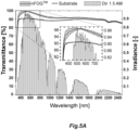
- Fig. 5a the average transmittance spectrum of seven nFOG TM coated samples is presented together with the spectra of a low iron float glass substrate and the AM1.5 direct solar spectrum].
- the substrate has a solar weighted transmittance of 89.5 % which on average is increased by 5.3 % to 94.8 % by the addition of the nFOG TM deposited mesoporous silica coating on both sides.
- a peak transmittance of 98.8 % at 535 nm is well adapted for solar thermal applications and agrees well with the TEM thickness measurements in Figs. 4d and 4e . This is in good agreement with simulations (Fig. 1d) and thickness measurements ( Figs. 4d, 4e and S1) indicating a thickness slightly below the ideal 120 nm. Furthermore, this supports that the slightly greater thickness from the profilometry measurements is caused by edge effects.
- the solar weighted transmittance of all nFOG TM samples fall within 94.5 and 95.1 % giving a reduction in solar weighted reflectance (R SW ) of 2.5-2.8 on each surface.
- the small interval in T SW and standard deviation, the shaded green area in Fig. 5a demonstrates a high reproducibility.
- the deviation in transmittance still present, originates from a slight variation in thickness, causing the peak transmittance to occur between 480 and 570 nm, which is also reflected in the higher standard deviation outside of the average peak at 535 nm.
- the T SW is significantly affected by the choice of substrate, as the differences can be several percent. However, the observed improvement of 5.3 % on average is in line with what have been reported for optimized single layer AR silica coatings.
- the T SW of two commercial coatings with open pore structure was measured to 94.0 - 94.4 % when deposited on the same substrate (evaluated with six samples each).
- a maintained transmittance at high incident angles is necessary for a cover glass.
- the transmittance spectra at incident angles from 0 to 60° are presented for the substrate with and without the AR nFOG TM coating in Figs. 5b and c , respectively.
- a largely maintained transmittance is observed up to an incident angle of 30°, after which it starts to slowly decrease before dropping significantly when moving from 50 to 60°.
- the coated sample exhibit a smaller drop than the substrate, especially at shorter wavelengths, ⁇ 800 nm, where the intensity of the solar irradiance is at its largest.
- Fig. 5d where the T SW of both samples at the different wavelengths, as well as the difference between the two, are presented. At normal incident angle they exhibit 94.7 and 89.3 % transmittance, respectively. The T SW then progressively drops with each step of 10° in incident angle to 91.4 and 86.4 %, respectively at 50°, before dropping significantly to 87.7 and 79.8 % at 60°. Consequently, the benefit of the AR coating increases with incident angle, in line with what has previously been reported. Disregarding the destructive interference from an appropriate coating thickness (Eq. 2), the benefit of the AR coating can be shown to increase with incident angle using Fresnel's reflectance equations.
- the present invention demonstrates, an antireflective (AR) mesoporous silica coating adapted for cover glass in solar thermal applications using nFOG TM and an aerosol-based deposition technique, has been shown.
- the pore structure of the coating is hexagonal, though not perfectly ordered, and the top surface is smooth and closed without pores open to the atmosphere.
- the thickness is approximately 110 nm, slightly below the 120 nm which by simulation was determined to be the ideal thickness.
- the coating is well adapted for solar thermal applications with a peak transmittance of 98.8 % at 535 nm and a solar weighted transmittance of approximately 95 % when applied on a low iron float glass substrate.
- nFOG TM has several advantages compared to conventional techniques like dip-coating, especially when it comes to scalability and materials saving. Furthermore, the closed pore structure and low surface roughness of the AR coating suggests a high cleanability and resistance to degradation from humidity.
Landscapes
- Engineering & Computer Science (AREA)
- Chemical & Material Sciences (AREA)
- Life Sciences & Earth Sciences (AREA)
- Mechanical Engineering (AREA)
- Materials Engineering (AREA)
- Thermal Sciences (AREA)
- Sustainable Development (AREA)
- Combustion & Propulsion (AREA)
- Physics & Mathematics (AREA)
- General Engineering & Computer Science (AREA)
- Sustainable Energy (AREA)
- Organic Chemistry (AREA)
- Chemical Kinetics & Catalysis (AREA)
- General Chemical & Material Sciences (AREA)
- Geochemistry & Mineralogy (AREA)
- Wood Science & Technology (AREA)
- Surface Treatment Of Glass (AREA)
- Paints Or Removers (AREA)
Description
- The present invention relates generally to improvements in antireflective coatings useful in solar collectors.
- In modern society energy is consumed by people and industries, e.g., for producing various products, for transport and production of food. Energy could be produced in several forms and from different energy sources. For instance, electricity is often produced from hydroelectric power plants, combustion of coal, oil, or gas. Traditionally, heat has been produced from local combustion or district heating power plants.
- With an increasing population and demands for services, energy consumption strongly increases which significantly negatively affects our environment. Combustion produces large amount of carbon dioxide and other greenhouse gases. Hydroelectric power plants require large territories to be drowned, etc.
- In order to reduce our footprint and negative impression on our environment, demands have been raised for cleaner and environmentally friendly energy production. Today, renewable energy is produced from wind, sun, ocean waves, etc. The sun provides large amounts of energy to our planet in form of radiated sun beams. Solar radiation can be used by solar cells to generate electricity, e.g., in form of solar panels, or by solar collectors to generate thermal heat.
- A concentrating solar collector uses mirrors, lenses, or combinations thereof, to focus the solar radiation in form of a point or a line. In trough-formed concentrating solar collectors a reflector is formed as a curved elongated mirror, which reflects the solar radiation on a receiver arranged along a focus-line of the reflector. The receiver is commonly a black tube filled with a transport fluid, such as water, glycol, or oil. The tube is heated by the concentrated solar radiation and the heat is transferred to the transport fluid that is circulated in a system where the heated transport fluid could be used. The heated transport fluid may be used both as process heat in industrial processes as for district heating.
- The term" PTC" (Parabolic Trough solar Collector) will be used in this disclosure to denote a concentrating solar collector with a trough-formed reflector arranged to concentrate solar light onto a fluid tube. Typically, PTCs will be pivoted to track the sun during the day and are controlled by a solar tracking arrangement.
- A parabolic trough solar collector comprises an elongated reflector, which reflective surface in a cross-section describes a parabolic curve. The reflector focuses direct sunlight on a focus. One example of closed PTC is disclosed in the patent publication
WO2010047656 A1 and is protected by a cover glass, to withstand e.g., rain, snow, sand etc. - Solar collectors are one of the first and most mature technologies of solar energy and have increased importance in the shift towards sustainable energy sources and is essential for reaching carbon neutrality. In all categories, the optical performance of the materials is of outmost importance for the efficiency. The cover glass optical performance is one of these components. In summary the cover glass for solar collectors is supposed to transmit as much of the solar irradiance as possible (i.e., in the entire spectrum) while also provide mechanical stability and impact resistance, chemical resistance and easy-to-clean surfaces. The cover glass is typically a float glass or possibly a rolled flat glass where the major optical losses are due to reflection (ca. 4% for each side) and minor absorption due to Fe2O3 impurities. Therefore, anti-reflective (AR) coatings are generally applied and for solar collector purposes, broadband anti-reflection is especially wanted.
- AR coatings can either be built up by single porous layers or by multiple thin films in order to achieve destructive interference of the reflected light. Sol-gel processing is a versatile, cheap and rapid method to create thin nanostructured films through a bottom-up approach using dip-, spin-, or spray-coating. It is a method that can be readily applied for anti-reflective coatings.
- Porous SiO2 is one of the most conventional anti-reflection coatings for glass, where a typical commercial glass has a refractive index of ca. 1.52 and the optimal broadband AR is obtained for a thin film with a thickness of λ/4 at the desired peak transmission wavelength. Such porous coatings frequently have disordered structures with pores open to the surface and generally need improvements to be more durable and more adapted for conditions of solar energy applications.
-
US6583071 discloses processes for forming a porous film with extremely low dielectric constant over a substrate. However, these films are not adapted in thickness for anti-reflective coatings and as such not adapted in porosity to improve usefulness in solar energy applications. - It is an object of the present invention to provide improved porous coatings with a suitable surface smoothness and a consistent coating thickness that mitigate problems with water adsorption/desorption and adhesion of dirt from the environment in solar energy applications.
- It is also an object of the invention to provide porous coatings with a controlled structural porosity and with pores not open to the ambient atmosphere.
- It is another object of the present invention is to provide an improved antireflective coating on a cover glass for solar collectors that has a suitably high transmittance over the solar wavelength spectrum and suitable reductions in solar weighted reflectance.
- In a first general aspect, the invention relates to an aerosol composition for antireflective coatings in solar energy applications obtained by a process of providing a sol gel composition comprising tetra alkyl orthosilicate Si(OR)4, wherein R is an alkyl group with 1 to 4 carbon atoms, a micelle forming surfactant, an aqueous acidic solution and a low alkyl alcohol solvent; diluting the sol gel composition with the low alkyl alcohol to a suitable viscosity for aerosolization, preferably diluting 1:3 by weight; and aerosolizing the diluted sol gel composition to an aerosol with a droplet size in the range of 0.5 to 50 µm, preferably from 1 to 20 µm. In this general aspect, solar energy application means solar thermal collectors and photovoltaics.
- The sol-gel composition comprises an amphiphilic block copolymer, preferably a block copolymer of ethylene glycol and propylene glycol, more preferably poly(ethylene glycol)- block- poly(propylene glycol)-block-poly(ethylene glycol) or a triblock copolymer comprising a central hydrophobic chain of polyoxypropylene surrounded by two chains of polyoxyethylene, such as at least one of Pluronic P123® and Polyoxamer 407. In one embodiment, the amphiphilic block copolymer is Pluronic P123®.
- Preferably the tetra alkyl orthosilicate of the sol gel is tetra ethyl orthosilicate (TEOS), for example
TEOS reagent grade 98%. Preferably, the low alkyl alcohol is ethanol and the aqueous acidic solution comprises hydrogen chloride and providing a pH of 1.5 to 2.5, preferably about 2. - The mass ratio between the micelle forming surfactant and the aqueous acidic solution is from 1:2 to 1:2.5. Preferably, the micelle forming surfactant is Pluronic P123® and/or Poloxamer 407. In one specific embodiment, the sol gel composition is prepared so the aerosol composition comprises Pluronic P123®, tetraethyl orthosilicate (TEOS,
reagent grade 98%), diluted hydrochloric acid (HCl 0.01 M) and absolute ethanol (EtOH) in the mass ratios 1:3.1:2.25:18.65. - In another aspect, the invention relates to a method of manufacturing a high transmittance antireflective (AR) coating on at least one substrate, comprising pre-treating the substrate(s) with at least one method suitable to increase the surface hydrophilicity; providing an aerosol composition in any embodiment as previously described. Following the pre-treatment, the at least one substate one surface exposed to the aerosol composition so the aerosol composition is homogenously distributed to a surface covering film with a thickness of less than 300 nm. Preferably, the aerosol composition is admitted to contact the at least one substrate surface in a coating chamber for a predetermined sufficient time period to provide a surface covering wet film, by means of transport gas flow or with gravitational settlement. In a next step substrate(s) with the surface covering film is/are subjected to one or more drying steps at temperatures between room temperature and 100° C; then calcinating the substrate by gradually increasing the temperature to over 400 °C, but below the glass temperature (Tg) of the substrate to form a coated substrate. Glass temperature is alternatively referred to as "glass transition temperature" in literature.
- In embodiments of the method, it comprises exposing at least one substrate with a controlled aerosol composition transport with a gas flow or by gravitation for a predetermined time period from 5 to 100 seconds, preferably 5 to 50 seconds.
- In embodiments of the method, it comprises transporting the aerosol with a transport gas flow rate of 0.05 to 2 L/h, preferably 0.5 to 2 L/h, and most preferably about 1 L/h.
- Preferably, the pre-treatment includes one or several steps wherein the surface is treated with at least one of a rinsing fluid, drying, air plasma cleaning. Various masking processes may be employed, such as application with brands of Resomer in a suitable solvent. The substrates may be coated on one or both sides. In important embodiments, the substates are cover glasses for solar collectors.
- Preferably, following the application of the aerosolized particles on the substrate surface the lower alcohol solvent evaporates, while the amphiphilic block copolymer self-assembles in to controlled structures (such as micelles) within the film and the silicate forms a network. During the calcination process, the amphiphilic block copolymer is removed together with remaining water, and the controlled pore structure is formed. In embodiments of the method, a suitable carrier gas flow (such as N2) is employed and adjusted to a suitable liquid feed flow and a suitable coating time inside a coating chamber was chosen to 15 s. After film forming, the substrates may be equilibrated for a short period and kept under control in a climate chamber at about ambient conditions before being transferred to a drying oven (60°C) where they were kept for another 24 hours. Finally, in one embodiment, the samples are calcinated in a high temperature oven by raising the temperature from room temperature to 450°C by 1°/min, then keeping the temperature at 450°C for 4 hours, where after the heating was switched of and the coating is finalized.
- In another aspect, the invention is directed to a substrate treated with embodiments of the methods as described, using an aerosol composition as described to manufacture an antireflective, porous coating on the substrate with a closed pore structure, i.e., without pores open to the ambient atmosphere.
- In embodiments of the invention, the substrate coating reduces the solar weighted reflectance according to ASTM G-173 AM1.5 direct solar spectrum of a substrate surface with at least 1.5 %, preferably at least 2.5, more preferably at least 3.5%.
- In embodiments of the invention, the substrate coating has an average thickness of 80 to 160 nm, preferably 100 to 140 nm, more preferably 110 to 130 nm, and most preferably about 120 nm.
- In embodiments of the invention the coated substrate has a diffraction peak in the interval of 1.2 to 1.8 q (nm-1), preferably 1.3 to 1.5 (nm-1) in a diffractogram from a GISAX analysis.
- In embodiments of the coated substate, as coated with the described methods by any described aerosol composition, is a low iron flat glass substrate.
- In embodiments of the invention the coated substrate has a transmittance ( T ) of at least 94% at wavelengths from 400 to 800 nm and an average transmittance ( T ) of at least 93% at a solar weighted spectrum according to ASTM G-173 AM1.5 direct solar spectrum.
- In one embodiment of the invention the coated substrate has an average transmittance peak at 535 nm, an average coating thickness of 110 to 130 nm and a coating with a refractive index of 1.15 to 1.35. Ideally the average thickness is about 120 nm and the refractive index is 1.28. Preferably the reduction in solar weighted reflectance according to ASTM G-173 AM1.5 direct solar spectrum is from 2.5 to 3.5%
- In embodiments of the invention the substrate has a coating with hexagonal mesoporous structure, wherein the hexagonal pores are elongated in a horizontal plane and closed to ambient air and wherein the porosity is in the range of 30 to 50%.
- In embodiments of the invention, the substrate has a coating that is hydrophilic with a water contact angle of less than 5. Preferably, water contact angle is measured with a water contact angle goniometer with which a 3 µL droplet of water was deposited,
- In embodiments of the invention the coated substrates are used as cover glasses in solar collectors.
- The invention is now described, by way of example, with reference to the accompanying drawings, in which:
-
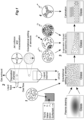
Figure 1 describes the synthesis process. 1. Mixing of the sol containing inorganic precursor (TEOS), ethanol, water, and surfactant at low pH, 2. Deposition of the sol using the aerosol method nFOG™, 3 Evaporation-induced self-assembly of micelles in an organized hexagonal network, 4. Decomposition of the organic template and stabilization of the inorganic network through calcination. -
Figures 2A-D show the function and simulation of AR coatings.Fig. 2A shows the schematic principles of a single-layer AR coating with hexagonal closed pores.Fig 2b shows the light transmittance of flat glass and AR coated flat glass and the effect of the refractive index and thickness of the AR coating with the solar spectrum in the background.Fig 2c shows the calculated refractive indices of glass (using Eq. 7), hexagonally mesoporous SiO2 (Eq. 3) and optimal refractive index as a function of wavelength for soda lime silicate based on the square root of Eq. 7 i.e., according to Eq. 2.Fig. 2d shows the simulated solar weighted transmittance evaluated through the Filmetrics calculated transmittance spectra in the wavelength range of 300-2500 nm (5 nm steps) is shown as a function of AR coating thickness. -
Figures 3A-D show pore structure characterization. Diffractograms of mesoporous silica films with hexagonal pore order (nFOG™-coated) inFig. 3A , hexagonal pore order (dip coated) inFig. 3B , and cubic pore orderinFig. 3C. Fig. 3D shows vertical integration (x=-0.002±0.04 nm-1) of the diffractograms inFigs.3A-D . -
Figures 4A-4I show pore structure characterization with electron microscopy. SEM images of the coating surfaces, show that the nFOG™ deposited one is very smooth (Fig. 4A ) while the dip-coated hexagonal one exhibit a largely closed surface with the occasional open pore and structure of elongated ridges with approximately 13 nm between the peaks (Fig. 4B ). The dip-coated cubic coating exhibit open, evenly distributed pores (Fig. 4C ). TEM images of the cross sections of nFOG™ (Figs. 4D-E ), hexagonal dip-coated (Figs. F-G ) and cubic dip-coated (Figs. H-I ) show the pore structure of the coatings for lamellas cut perpendicular to each other. Only the dip-coated hexagonal coating exhibits a difference in porosity depending on the angle of the lamella. Note that the substrate is the brighter region to the right of the coatings inFigs. D-I ). -
Figures 5A-5D show optical properties of the nFOG™ deposited hexagonal silica coating.Fig. 5A shows the average transmittance and standard deviation (dotted) of the nFOG™ coated samples presented together with the spectra of a low iron float glass substrate and the AM1.5 direct solar spectrum (see ASTM Standard G173, Standard Tables for Reference Solar Spectral Irradiances: Direct Normal and Hemispherical on 39° Tilted Surface, A. International, 2020).The transmittance spectra at incident angles of 0 to 60° for the low iron float glass substrate with (Fig 5B ) and without (Fig. 5C ) the nFOG™ deposited AR coating.Fig. 5D shows the angle dependent solar weighted transmittance of the substrate with and without the nFOG™ AR coating as well as the difference between the two shows that the benefit of the AR coating increases at high incident angles. -
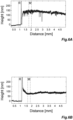
Figures 6A and 6B illustrate graphs of Profilometer measurement of hexagonal coatings deposited with nFOG™ (Fig. 6A ) and dip-coating (Fig. 6B ).Figures 7A-7D illustrate Optical profilometry images showing the surface topography of four locations on a hexagonal antireflective coating deposited by nFOG™. Note that the interference pattern from the optical profilometer creates some periodic surface topography as due to the limited reflections VSI mode was used. -
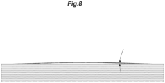
Figure 8 shows the contact angle in a representative droplet after reaching steady state on the nFOG coating AR coating. - In the following experimental part of the invention, it is described how to obtain an ordered hexagonally structured silica coating with suitable characteristics, based on evaporation-induced self-assembly and how to optimize antireflective (AR) behavior with purpose of making AR thin films on float glass in parabolic solar collectors. The AR properties were optimized by simulating the transmittance for various thicknesses and refractive indices of the thin film, according to the effective medium theory. The thin films were prepared using the aerosol-assisted spray coating technique nFOG™, as described in Journal of Coatings Technology and Research, (2018). doi: 10.1007/s11998-017-0022 and dip-coating as a reference. The deposition mechanism of the aerosol was based on gravitational settling of droplets with a dual size distribution where smaller ones are ~1-2 µm in diameter and larger ones >10 µm, which leads to a very uniform coating thickness.
- To further asses the structures of the resulting coatings Scanning Electron Microscopy (SEM), Transmission Electron Microscopy (TEM), and Gracing-Incidence Small Angle X-ray Spectroscopy (GISAXS) were used. The optical performance of the coatings was studied with UV-Vis-NIR transmittance in comparison to simulation and commercial alternatives. The film thickness of the coated layers and surface topography were studied by contact and optical profilometry, respectively.
- The glass substrate used was a 4 mm thick Pilkington Optiwhite, which is a commercial "low iron" flat glass [28] manufactured according to the float process [12]. Coatings were also applied on double polished silicon wafers (Wafernet, US), which were P-type Boron doped with a <100> direction.
- For the preparation of mesoporous SiO2 films, see
Fig. 1 for the schematic procedure. The synthesis protocols by Alberius et al. in Chem. Matter, 2002, vol.14, pp. 3284-3294 and Hutchinson et al. in Thin Sold Films 2010, Vol. 518 pp. 2134-2140 were followed with small modifications. Films of hexagonal pore ordering were prepared by mixing Poloxamer 407, tetraethyl orthosilicate (TEOS,reagent grade 98 %), diluted hydrochloric acid (HCl 0.01 M) and absolute ethanol (EtOH) in the mass ratios 1:3.1:2.25:18.65. The final sol was aged for 3 days before use. The substrate (glass or silicon wafer) was cleaned by rinsing with isopropanol (IPA), ethanol and water, and dried with pressurized air. Just prior to coating, the substrate was air plasma cleaned for 5 min. Some samples were masked by applying a drop of Resomer 207 S (10 wt%) dissolved in acetone. - In the case of dip-coating, the substrate was dipped in the sol at room temperature using a dipping robot (Texture analyzer, Stable Microsystems, UK) at a speed of 45 mm/min.
- In the case of nFOG™, the aged sol was diluted with ethanol 1:3 by weight just prior to use. The carrier gas (N2) flow was adjusted to 25 L/min, the liquid feed rate 1 L/h, and the coating time inside the chamber was chosen to 15 s. The samples (5 cm x 5 cm) were mounted in a soft Teflon frame in order to avoid coating of the backside. After coating, the samples were left in the prechamber of the nFOG™-equipment to equilibrate for 60 s, then they were transferred to a fume hood for drying. After coating both sides of the substrate, the samples were kept in a climate chamber with a controlled climate of 23°C and 90 % RH for 24 hours. The samples were then transferred to an oven (60°C) where they were kept for another 24 hours. Finally, the samples were calcined in a high temperature oven by raising the temperature from room temperature to 450°C by 1°/min, then keeping the temperature at 450°C for 4 hours, where after the heating was switched of.
- For comparison reasons, thin films with pores of cubic ordering were synthesized by mixing Pluronic P123®, TEOS, HCl (0.01 M), and EtOH in the mass ratio 1:6.13:3.22:11.87. The substrate (silicon wafer) was dip-coated at 15°C at a speed of 45 mm/min and post treated in the same way as described above.
- Grazing-Incidence Small Angle X-ray Spectroscopy (GISAXS) measurements were performed on an Anton Paar SAXSpoint 2.0 system (Anton Paar, Graz, Austria) equipped with a Microsource X-ray source (Cu K-alpha radiation, wavelength 0.15418 nm) and a Dectris 2D CMOS Eiger R 1M detector with 75x75 µm pixel size. All measurements were performed with a beam size of approximately 500 µm diameter and a beam path pressure at about 1-2 mbar. The sample to detector distance (SDD) was 584 mm during the measurements. Samples were mounted on a sample plate on the GISAXS stage that was mounted on a VarioStage x-stage (Anton Paar, Graz, Austria). The samples were exposed to vacuum during measurement. For each sample, the total measurement time was 10 to 30 minutes. The software used for instrument control was SAXSdrive version 2.01.224 (Anton Paar, Graz, Austria), and post-acquisition data processing was performed using the software SAXSanalysis version 4.00.046 (Anton Paar, Graz, Austria).
- The surface and bulk morphology of the mesoporous silica coating was investigated using SEM and TEM, respectively. The SEM imaging was performed on coatings deposited on silicon wafers to avoid charging and need of a conducting top layer. A Carl Zeiss Merlin FESEM (Field Emission Scanning Electron Microscope) was used, and the imaging was conducted using an acceleration voltage of 15 kV and an in-lens secondary electron detector.
- The pore structure in the bulk of the coating was imaged using a Jeol TEM 1230 operating at 80 kV. Lamellas of 80 nm thickness was cut out of the surface using a focused ion beam (Thermo Fisher FEI Scios FIB-SEM) exposing the cross section of the coating. The lamellas were fused to a TEM grid ta facilitate imaging in the TEM. Considering the hexagonal pore structure of the coating, two lamellas oriented perpendicularly to each other was cut from each sample.
- The film thickness of the mesoporous layers was evaluated with a Dektak XT (Bruker, US) stylus profilometer. The radius of the stylus was 2 µm and a force of 3 mg was applied with a scan length of 5 mm. The film thickness is reported as an average and standard deviation from at least three different scan lines over the edge between the substrate and the coating.
- The surface roughness of the thin films was measured using an optical profilometer instrument from Bruker Corporation, NPFLEX 3D Surface Metrology System equipped with an objective with 5x magnification. The measurements were performed in the Vertical Scanning Interferometer (VSI) mode using Field of View option so that the magnification of the acquired surfaces is 2.7x. Post-processing was made in the software Vision using tilt only for plane fit and height scale user limits of ±30 nm. In total four images of the size 1.7x2.3 mm were acquired, and the Rq-values (root mean square, rms) recorded as an average with the standard deviation as the error.
- The transmittance spectrum, T(λ), was measured over 300-2500 nm with a step length of 5 nm using a Perkin Elmer Lambda 1050 spectrophotometer. From this transmittance spectrum, the solar weighted transmittance (Tsw) was calculated using

- The following relations (Eq. 2 and Eq. 3) are well-known conditions for achieving an optimal AR coating and see
Fig. 2a for a schematic picture of the principle.

Fig. 2b . - Also, from Eq. 2 and 3 it becomes obvious that for any given refractive index of the AR coating there is an optimal AR coating thickness and vice versa. To simulate the refractive index of the AR coating the effective medium theory (EMT) was used. This method determines the effective index of refraction (neff) of a sub-wavelength structured geometry on the volume fill factors of multiple materials. Important to note, EMT is only valid when the period of the texture is much smaller than the wavelength of the light and it does not account for the size, shape, arrangement of subwavelength textured materials, or the polarization of the incident wave on a grating. In general, neff falls between the upper and lower indices of a subwavelength mixture of materials set by their respective bulk refractive indices for the constituent materials. There are many models for EMT but Garahan et al in Journal of Applied Physics 101 (2007) 014320. doi: 10.1063/1.240232 found that the volume averaging theory (VAT) shows good agreement with numerical finite element method simulations for both neff and the effective absorption index (keff). We have therefore used the VAT model to determine neff for our hexagonally mesoporous thin films according to Eq. 4,


Fig. 2c . The refractive index of glass can be calculated to the third decimal for soda lime silicate glass (i.e. typical float glass) by use of a simplified dispersion equation (Eq. 8).
- Then we used the Filmetrics online Reflectance Calculator, Filmetrics Reflectance Calculator. (2020). KLA Corporation, https://www.filmetrics.com/reflectance-calculator, to calculate the transmittance spectra. It is based on the complex matrix form of the Fresnel equations. The input data was the refractive index of the glass substrate (nglass=1.5216 at 632.8 nm as given from Eq. 8) and the refractive index of the AR thin film (neff= 1.276 at 632.8 nm as given from Eq. 4). Note that the reason for using 632.8 nm is because it is the operating wavelength of the He-Ne laser.
- Prior to measuring the contact angle the samples were rinsed in IPA, ethanol and deionized water for approx. 5 s with each liquid before being dried with pressurized air. The measurement was performed with a
Dataphysics OCA 40 instrument with which a 3 µL droplet of water was deposited on the sample filmed during the process of reaching a stable droplet shape. Upon reaching steady state the contact angle was measured. The measurement was performed on three samples and at two locations on each sample resulting in a total of six measurements. - In order to optimize the transmittance of solar photons for heat conversion in the solar collector, the entire solar spectrum is of interest. In the simulation, in order to simplify, a constant refractive index over the entire spectrum for both the substrate and the AR thin film, is assumed. The simulation is thus not simulating the real thin films on glass as our simplified simulation do not consider any absorption in the glass (e.g., iron impurities, inhomogeneities in the film structure or thickness etc. Instead, the purpose was to find optimal film thickness from a given effective refractive index of the thin film.
Fig. 2c shows the refractive index as a function of wavelength and that our assumption of a constant refractive index is valid for most parts of the spectrum. - The transmittance spectra can be difficult to interpret in terms of optimization, so the solar weighted transmittance is used (see Eq. 1) as a figure of merit. The refractive index is determined by the porosity in the film, which is constant for our hexagonal coating. The porosity was estimated to 45 % by Hutchinson et al for similar films, see Thin Solid Films 518 (2010) 2134-2140, resulting in a refractive index of 1.276 used for the simulations. In
Fig. 2d the shows the effect of the thickness of the AR coating on the solar weighted transmittance is presented. For the obtained refractive index 1.276 an optimum in AR will be achieved at a film thickness of 120 nm. - GISAXS diffractograms of dip coated cubic and hexagonal samples resemble 2D-SAXS patterns and 1D-XRD (x-ray diffraction) intensity measurements reported in literature [21]. The pore ordering of the sample prepared with nFOG™ is hexagonal according to the GISAXS analysis, see
Figures 3A-C . Minor differences can be observed in GISAXS diffractograms of the hexagonal samples, seeFig. 3D . It appears that the sampled prepared with nFOG™ has shorter lattice distances compared to the dip coated ones, as well as a somewhat higher degree of disorder, since the peak is shifted to the right at higher q values and is lower in intensity. - SEM imaging of the nFOG™ deposited AR coating shows a surface that is completely smooth with no open pores, apparent defects, or indication as to the underlying pore structure, see
Fig. 4a . However, inFigs. 4d and 4e , TEM images of the cross section show elongated pores oriented horizontal to the substrate, indicating a hexagonal pore structure. There are regional differences, with distinct pores in some regions and a less ordered mesoporous structure in other. This is in line with the GISAXS data indicating a hexagonal but slightly disordered structure. Additionally, there is no significant difference in pore orientation between the lamellas perpendicular to each other. For a perfect hexagonal pore structure, the elongation of the pores in one direction would result in a visible difference, further supporting a somewhat less ordered structure. - From
Figs. 4d and 4e , thicknesses of 109 nm and 104 nm was determined for the two nFOG™ lamellae. Evidently, the thickness varies slightly across the sample, which is also apparent fromFig. 4e . This thickness correlates reasonably well with the thickness measured with stylus profilometry of 129 ± 8 nm, seeFigs 6a and 6b for a representative scan. Based on the trend of decreasing thickness further from the edge the difference is attributed to edge effects. It is also evident that the high smoothness apparent on the SEM (Fig. 4a ) does not translate to the larger scale of the profilometer measurement (Figs 6a and 6b ). However, optical profilometry measurements show that the coating has good thickness homogeneity, with an average root mean square roughness (Rq) value of 20.55±3.80 nm, which is in line with thin films deposited by dip-coating. 3D images of the measured surfaces can be seen inFigs 7a-7d . - The assumed porosity of 45 % gives a refractive index of 1.276, if we use that and the thicknesses of 104 and 109 nm in Eq. 2, the transmittance peaks are at wavelengths 531 and 556 nm, respectively. This is in good agreement with the peak of the AM1.5 direct solar irradiance spectrum and thus well adapted for solar thermal applications. However, based on our simulations, it is slightly below the ideal thickness of 120 nm, see
Fig. 2d . - In
Fig. 4b SEM image of the dip-coated sample exhibit a surface of elongated ridges with approximately 13 nm between the peaks, indicating a lattice parameter on the same order. This is in line with Hutchinson et al. and supports the assumption of a porosity of 45 %. The surface is largely closed, except for a few small circular pores, presumably created by the surfactant during the calcination as it evaporates and escapes from the underlying pores. This is in line with literature for a well-ordered hexagonal pore structure, both in terms of appearance and lattice parameter. Furthermore, the TEM images show that the pores are elongated and parallel to the substrate in one direction (Fig. 4f ) while in the perpendicular direction, though not perfectly distinct, the pores resemble ellipsoids (Fig. 4g ). This clearly indicates the directional differences of a hexagonal pore structure with cuts along and across the elongated pores. - The thicknesses of the dip coated hexagonal samples, shown in
Figs. 4f and 4g , of 82 and 85 nm indicate a variation on a similar level to the nFOG™ samples. This thickness evaluation is in excellent agreement with the profilometer data of 82 ± 8 nm, seeFig 6a and 6b . The profilometer data also show that the surface of the dip-coated hexagonal film is smoother than the nFOG™ deposited one on the mm scale, unlike on the nm scale of the SEM imaging (figure 3e). - In
Fig 4c , the SEM image of the coating with a cubic pore structure exhibit the characteristically organized open pores on the surface. However, in the TEM images of the cross section inFigs. 4h and 4i , only the lattice planes are distinguishable, because the lamella is not thin enough to reveal the individual pores. As expected for a symmetrical pore structure, no variation is seen between the perpendicular lamellae. - Based on the images in
Fig. 4 , the nFOG™ coating has a hexagonal, but slightly less ordered, pore structure than the dip-coated one. The most likely reason for this difference between the two deposition methods is the different drying processes. When dip coating, the evaporation occurs in a controlled way from the top downwards during withdrawal of the sample from the sol. In the nFOG™ process, the sample was left in the prechamber and allowed to equilibrate for 30 s while still being wet, and then taken out to dry in a fume hood. The resulting simultaneous evaporation over the entire horizontal nFOG™ sample could possibly disrupt the micelle formation during the gelation process, as opposed to the gradual vertical evaporation from the sol used for the dip-coating through which the micelles are evidently maintained. The gelation process is known to be sensitive to a variety of factors, and it is consequently reasonable that the change in deposition method, and more specifically the difference in drying, has an effect on the pore structure formed. Further optimization of the drying process could improve the order of the nFOG™ deposited films. - Regardless of how ordered it is, the nFOG™ coating is porous, exhibits a closed and smooth surface and has a thickness suitable for solar thermal applications. This is in stark contrast to the open pore structure of most commercial AR silica coatings used for solar thermal and other applications. The open pores have been associated with poor cleanability and increased sensitivity to humidity and pollution, whereas a low surface roughness, like the one of the nFOG™ coating, is associated with high cleanability. This issue can be managed with protective top coatings, like TiO2, but at the expense of a decreased transmittance. The presented nFOG™ coating thus proposes a cheaper, easier, and more efficient potential solution.
- In
Fig. 5a the average transmittance spectrum of seven nFOG™ coated samples is presented together with the spectra of a low iron float glass substrate and the AM1.5 direct solar spectrum]. The substrate has a solar weighted transmittance of 89.5 % which on average is increased by 5.3 % to 94.8 % by the addition of the nFOG™ deposited mesoporous silica coating on both sides. A peak transmittance of 98.8 % at 535 nm is well adapted for solar thermal applications and agrees well with the TEM thickness measurements inFigs. 4d and 4e . This is in good agreement with simulations (Fig. 1d) and thickness measurements (Figs. 4d, 4e and S1) indicating a thickness slightly below the ideal 120 nm. Furthermore, this supports that the slightly greater thickness from the profilometry measurements is caused by edge effects. - The solar weighted transmittance of all nFOG™ samples fall within 94.5 and 95.1 % giving a reduction in solar weighted reflectance (RSW) of 2.5-2.8 on each surface. The small interval in TSW and standard deviation, the shaded green area in
Fig. 5a , demonstrates a high reproducibility. The deviation in transmittance still present, originates from a slight variation in thickness, causing the peak transmittance to occur between 480 and 570 nm, which is also reflected in the higher standard deviation outside of the average peak at 535 nm. - The TSW is significantly affected by the choice of substrate, as the differences can be several percent. However, the observed improvement of 5.3 % on average is in line with what have been reported for optimized single layer AR silica coatings. The TSW of two commercial coatings with open pore structure (Migo Glass and Sunarc) was measured to 94.0 - 94.4 % when deposited on the same substrate (evaluated with six samples each).
- As solar collectors are commonly either stationary (flat) or one axis solar tracking (parabolic trough and Fresnel) a maintained transmittance at high incident angles is necessary for a cover glass. The transmittance spectra at incident angles from 0 to 60° are presented for the substrate with and without the AR nFOG™ coating in
Figs. 5b andc , respectively. In both cases a largely maintained transmittance is observed up to an incident angle of 30°, after which it starts to slowly decrease before dropping significantly when moving from 50 to 60°. The coated sample exhibit a smaller drop than the substrate, especially at shorter wavelengths, <800 nm, where the intensity of the solar irradiance is at its largest. - The effect of this divergence in behavior is illustrated further in
Fig. 5d where the TSW of both samples at the different wavelengths, as well as the difference between the two, are presented. At normal incident angle they exhibit 94.7 and 89.3 % transmittance, respectively. The TSW then progressively drops with each step of 10° in incident angle to 91.4 and 86.4 %, respectively at 50°, before dropping significantly to 87.7 and 79.8 % at 60°. Consequently, the benefit of the AR coating increases with incident angle, in line with what has previously been reported. Disregarding the destructive interference from an appropriate coating thickness (Eq. 2), the benefit of the AR coating can be shown to increase with incident angle using Fresnel's reflectance equations. - The results from the experiments outlined above in paragraph 2.7 demonstrate that the contact angle of the nFOG deposited AR coating is below 5°, which is the lower measurable limit of the equipment used, see
Fig.8 . The extremely low contact angle results in a superhydrophilic surface where almost complete wetting is achieved. Having a superhydrophilic surface is preferable for a solar glass as it achieves a somewhat self-cleaning surface. This is due to the high wetting which results in the water spreading out in a film which makes it harder for dirt to attach to the surface, and it also improves cleanability of the surface. A hydrophobic surface is also self-cleaning, but the droplets cause scattering of light making hydrophilic surfaces preferable for solar thermal applications. - Accordingly, the present invention demonstrates, an antireflective (AR) mesoporous silica coating adapted for cover glass in solar thermal applications using nFOG™ and an aerosol-based deposition technique, has been shown. In preferred embodiments, the pore structure of the coating is hexagonal, though not perfectly ordered, and the top surface is smooth and closed without pores open to the atmosphere. The thickness is approximately 110 nm, slightly below the 120 nm which by simulation was determined to be the ideal thickness. In terms of optical properties, the coating is well adapted for solar thermal applications with a peak transmittance of 98.8 % at 535 nm and a solar weighted transmittance of approximately 95 % when applied on a low iron float glass substrate. At high incident angles the benefit of the AR coating increases, manifested in an improvement of 7.9 % in solar weighted transmittance relative to the substrate at 60° incident angle. To conclude, our results show that high quality AR coatings can be manufactured using the nFOG™ technique. nFOG™ has several advantages compared to conventional techniques like dip-coating, especially when it comes to scalability and materials saving. Furthermore, the closed pore structure and low surface roughness of the AR coating suggests a high cleanability and resistance to degradation from humidity.
Claims (16)
- An aerosol composition for antireflective coatings in solar energy applications obtained by a process of:- providing a sol gel composition comprising tetra alkyl orthosilicate Si(OR)4, wherein R is an alkyl group with 1 to 4 carbon atoms, a micelle forming surfactant, an aqueous acidic solution and a low alkyl alcohol solvent;- diluting the sol gel composition with the low alkyl alcohol to a suitable viscosity, preferably diluting 1:3 by weight; and- aerosolizing the diluted sol gel composition to an aerosol with a droplet size of 0.5 to 50 µm, preferably from 1 to 20 µm,wherein the mass ratio between the micelle forming surfactant and the aqueous acidic solution is from 1:2 to 1:2.5,and wherein the sol-gel composition comprises an amphiphilic block copolymer.
- The composition according to claim 1, wherein the amphiphilic block copolymer comprises a block copolymer of ethylene glycol and propylene glycol, preferably poly(ethylene glycol)- block- poly(propylene glycol)-block-poly(ethylene glycol).
- The composition according to claim 1 or 2, wherein the tetra alkyl orthosilicate is tetra ethyl orthosilicate (TEOS), the low alkyl alcohol is ethanol and aqueous acidic solution comprises hydrogen chloride and has a pH of 1.5 to 2.5, preferably about 2.
- A method of manufacturing a high transmittance antireflective (AR) coating on a substrate for solar energy applications; comprising:- pre-treating the substrate with at least one method suitable increase the surface hydrophilicity;- providing an aerosol composition according to any one of claims 1 to 3;- exposing at least one substrate surface to the aerosol composition so the aerosol composition is homogenously distributed to a surface covering film with a thickness of less than 300 nm;- subjecting the substrate with the surface covering film to one or more drying steps at temperatures between room temperature and 100° C; and- calcinating the substrate by gradually increasing the temperature to over 400 °C, but below the glass temperature (Tg) of the substrate to form a coated substrate.
- The method according to claim 4, comprising exposing at least one substrate with a controlled aerosol composition transport with a gas flow or by gravitation for a predetermined time period from 5 to 100 seconds, preferably from 5 to 50 seconds.
- The method according to claim 5, comprising transporting the aerosol with a flow rate of 0.05 to 2L/h, preferably 0.5 to 2 L/h, and most preferably about 1 L/h.
- A substrate treated with a method according any one of claims 4 to 6, using the composition of claims 1 to 3 to manufacture an antireflective, porous coating on the substrate with a closed pore structure, i.e., without pores open to the ambient atmosphere.
- The substrate according to claim 7 wherein the coating reduces the solar weighted reflectance according to ASTM G-173 AM1.5 direct solar spectrum of a substrate surface with at least 1.5 %, preferably at least 2.5, more preferably at least 3.5%.
- The substrate according to any one of claims 7 or 8, wherein the coating has an average thickness of 80 to 160 nm, preferably 100 to 140 nm, more preferably 110 to 130 nm, and most preferably about 120 nm.
- The substrate according to any one of claims 7 to 9, having a diffraction peak in the interval of 1.2 to 1.8 q (nm-1), preferably 1.3 to 1.5 (nm-1) in a diffractogram from a GISAX analysis.
- The substrate according to any one of claims 7 to 10 consisting of low iron flat glass.
- The substrate according to any one of claims 7 to 10 with a transmittance ( T ) of at least 94% at wavelengths from 400 to 800 nm and an average transmittance ( T ) of at least 93% at a solar weighted spectrum according to ASTM G-173 AM1.5 direct solar spectrum.
- The substrate according to any one of claims 7 to 12, having an average transmittance peak at 535 nm, an average coating thickness of 110 to 130 nm and a coating with a refractive index of 1.15 to 1.35.
- The substrate according to any one of claims 7 to 13, having a coating with hexagonal mesoporous structure, wherein the hexagonal pores are elongated in a horizontal plane and closed to ambient air and wherein the porosity is in the range of 30 to 50%.
- The substrate according to any one of claims 7 to 14, wherein the coating is hydrophilic with a water contact angle of less than 5.
- Use of a substrate according any one of claims 7 to 15 as a cover glass in a solar collector.
Applications Claiming Priority (2)
| Application Number | Priority Date | Filing Date | Title |
|---|---|---|---|
| SE2130201A SE2130201A1 (en) | 2021-07-16 | 2021-07-16 | Antireflective coatings |
| PCT/EP2022/069701 WO2023285578A1 (en) | 2021-07-16 | 2022-07-14 | Antireflective coatings |
Publications (3)
| Publication Number | Publication Date |
|---|---|
| EP4370477A1 EP4370477A1 (en) | 2024-05-22 |
| EP4370477B1 true EP4370477B1 (en) | 2025-01-15 |
| EP4370477C0 EP4370477C0 (en) | 2025-01-15 |
Family
ID=82611201
Family Applications (1)
| Application Number | Title | Priority Date | Filing Date |
|---|---|---|---|
| EP22744193.8A Active EP4370477B1 (en) | 2021-07-16 | 2022-07-14 | Antireflective coatings |
Country Status (4)
| Country | Link |
|---|---|
| EP (1) | EP4370477B1 (en) |
| ES (1) | ES3020684T3 (en) |
| SE (1) | SE2130201A1 (en) |
| WO (1) | WO2023285578A1 (en) |
Families Citing this family (1)
| Publication number | Priority date | Publication date | Assignee | Title |
|---|---|---|---|---|
| CN121263389A (en) * | 2023-05-31 | 2026-01-02 | 旭硝子欧洲玻璃公司 | Porous anti-reflection coating for near infrared sensor covers |
Family Cites Families (6)
| Publication number | Priority date | Publication date | Assignee | Title |
|---|---|---|---|---|
| EP1094506A3 (en) * | 1999-10-18 | 2004-03-03 | Applied Materials, Inc. | Capping layer for extreme low dielectric constant films |
| CA2404013A1 (en) * | 2000-04-21 | 2001-11-01 | Hongyou Fan | Prototyping of patterned functional nanostructures |
| SE533498C2 (en) | 2008-10-22 | 2010-10-12 | Absolicon Solar Concentrator Ab | Installation of receiver in solar collector trough |
| US20110151222A1 (en) * | 2009-12-22 | 2011-06-23 | Agc Flat Glass North America, Inc. | Anti-reflective coatings and methods of making the same |
| ES2480791B8 (en) * | 2012-12-27 | 2015-10-19 | Abengoa Solar New Technologies, S.A. | PROCEDURE FOR OBTAINING ANTI-REFLECTIVE COATING FOR OPTICAL AND THERMOELECTRIC DEVICES |
| ES2876251T3 (en) * | 2017-01-16 | 2021-11-12 | Fundacion Tecnalia Res & Innovation | A broadband anti-reflective sol-gel coating composition |
-
2021
- 2021-07-16 SE SE2130201A patent/SE2130201A1/en unknown
-
2022
- 2022-07-14 ES ES22744193T patent/ES3020684T3/en active Active
- 2022-07-14 EP EP22744193.8A patent/EP4370477B1/en active Active
- 2022-07-14 WO PCT/EP2022/069701 patent/WO2023285578A1/en not_active Ceased
Also Published As
| Publication number | Publication date |
|---|---|
| WO2023285578A1 (en) | 2023-01-19 |
| SE2130201A1 (en) | 2023-01-17 |
| EP4370477C0 (en) | 2025-01-15 |
| EP4370477A1 (en) | 2024-05-22 |
| ES3020684T3 (en) | 2025-05-23 |
Similar Documents
| Publication | Publication Date | Title |
|---|---|---|
| Joshi et al. | Super-hydrophilic broadband anti-reflective coating with high weather stability for solar and optical applications | |
| Rad et al. | Anti-reflection and self-cleaning meso-porous TiO2 coatings as solar systems protective layer: Investigation of effect of porosity and roughness | |
| Helsch et al. | Compatibility of antireflective coatings on glass for solar applications with photocatalytic properties | |
| Li et al. | Broadband anti-reflective and water-repellent coatings on glass substrates for self-cleaning photovoltaic cells | |
| Nielsen et al. | Large area, low cost anti-reflective coating for solar glasses | |
| US9181455B2 (en) | Method of making hydrophobic coated article, coated article including hydrophobic coatings, and/or sol compositions for use in the same | |
| Agustín-Sáenz et al. | Broadband antireflective coating stack based on mesoporous silica by acid-catalyzed sol-gel method for concentrated photovoltaic application | |
| Wu et al. | Gradient refractive index-based broadband antireflective coatings and application in silicon solar modules | |
| Ma et al. | Broadband antireflection and hydrophobic CaF2 film prepared with magnetron sputtering | |
| Agustín-Sáenz et al. | Antireflective mesoporous silica coatings by optimization of water content in acid-catalyzed sol-gel method for application in glass covers of concentrated photovoltaic modules | |
| Agustín-Sáenz et al. | Hydrophobic and spectrally broadband antireflective methyl-silylated silica coatings with high performance stability for concentrated solar applications | |
| Tao et al. | A hydrophobic ultralow refractive-index silica coating towards double-layer broadband antireflective coating with exceptionally high vacuum stability and laser-induced damage threshold | |
| Wang et al. | Durable superhydrophilic and antireflective coating for high-performance anti-dust photovoltaic systems | |
| Zäll et al. | Aerosol-based deposition of broadband antireflective silica coating with closed mesoporous structure | |
| Chi et al. | Enhancing mechanical stability of sol-gel silica antireflection coatings via ammonia treatment at low temperature | |
| Pinto et al. | Random subwavelength structures on glass to improve photovoltaic module performance | |
| CN110461791B (en) | Broad band antireflective sol-gel coating compositions | |
| Manna et al. | Mesoporous silica-based abrasion resistant antireflective (AR)-cum-hydrophobic coatings on textured solar cover glasses by a spray coating technique | |
| EP4370477A1 (en) | Antireflective coatings | |
| Wang et al. | Superhydrophilic antireflection films with excellent optical and mechanical performance for perovskite solar cells | |
| Chandralekha et al. | Enhanced optical performance of solar cell using hydrophobic SnO2/TEOS/MTMS antireflection coating | |
| Wang et al. | Anti-reflection silica coating simultaneously achieving superhydrophobicity and robustness | |
| Zahid et al. | Improved optical performance of hydrophobic silica nanoparticles as antireflection coating on glass and its electrical performance for photovoltaic module applications | |
| Alam et al. | Super hydrophilic nano particulate coating for solar PV module | |
| Jin et al. | Preparation of TiO2-SiO2 double-layer broadband antireflective coating with long-lasting superhydrophilicity |
Legal Events
| Date | Code | Title | Description |
|---|---|---|---|
| STAA | Information on the status of an ep patent application or granted ep patent |
Free format text: STATUS: UNKNOWN |
|
| STAA | Information on the status of an ep patent application or granted ep patent |
Free format text: STATUS: THE INTERNATIONAL PUBLICATION HAS BEEN MADE |
|
| PUAI | Public reference made under article 153(3) epc to a published international application that has entered the european phase |
Free format text: ORIGINAL CODE: 0009012 |
|
| STAA | Information on the status of an ep patent application or granted ep patent |
Free format text: STATUS: REQUEST FOR EXAMINATION WAS MADE |
|
| 17P | Request for examination filed |
Effective date: 20240112 |
|
| AK | Designated contracting states |
Kind code of ref document: A1 Designated state(s): AL AT BE BG CH CY CZ DE DK EE ES FI FR GB GR HR HU IE IS IT LI LT LU LV MC MK MT NL NO PL PT RO RS SE SI SK SM TR |
|
| GRAP | Despatch of communication of intention to grant a patent |
Free format text: ORIGINAL CODE: EPIDOSNIGR1 |
|
| STAA | Information on the status of an ep patent application or granted ep patent |
Free format text: STATUS: GRANT OF PATENT IS INTENDED |
|
| INTG | Intention to grant announced |
Effective date: 20240822 |
|
| DAX | Request for extension of the european patent (deleted) | ||
| RAV | Requested validation state of the european patent: fee paid |
Extension state: TN Effective date: 20240112 Extension state: MA Effective date: 20240112 |
|
| GRAS | Grant fee paid |
Free format text: ORIGINAL CODE: EPIDOSNIGR3 |
|
| GRAA | (expected) grant |
Free format text: ORIGINAL CODE: 0009210 |
|
| STAA | Information on the status of an ep patent application or granted ep patent |
Free format text: STATUS: THE PATENT HAS BEEN GRANTED |
|
| AK | Designated contracting states |
Kind code of ref document: B1 Designated state(s): AL AT BE BG CH CY CZ DE DK EE ES FI FR GB GR HR HU IE IS IT LI LT LU LV MC MK MT NL NO PL PT RO RS SE SI SK SM TR |
|
| REG | Reference to a national code |
Ref country code: CH Ref legal event code: EP Ref country code: GB Ref legal event code: FG4D |
|
| REG | Reference to a national code |
Ref country code: DE Ref legal event code: R096 Ref document number: 602022009638 Country of ref document: DE |
|
| REG | Reference to a national code |
Ref country code: IE Ref legal event code: FG4D |
|
| U01 | Request for unitary effect filed |
Effective date: 20250204 |
|
| U07 | Unitary effect registered |
Designated state(s): AT BE BG DE DK EE FI FR IT LT LU LV MT NL PT RO SE SI Effective date: 20250210 |
|
| REG | Reference to a national code |
Ref country code: ES Ref legal event code: FG2A Ref document number: 3020684 Country of ref document: ES Kind code of ref document: T3 Effective date: 20250523 |
|
| PG25 | Lapsed in a contracting state [announced via postgrant information from national office to epo] |
Ref country code: RS Free format text: LAPSE BECAUSE OF FAILURE TO SUBMIT A TRANSLATION OF THE DESCRIPTION OR TO PAY THE FEE WITHIN THE PRESCRIBED TIME-LIMIT Effective date: 20250415 |
|
| PG25 | Lapsed in a contracting state [announced via postgrant information from national office to epo] |
Ref country code: PL Free format text: LAPSE BECAUSE OF FAILURE TO SUBMIT A TRANSLATION OF THE DESCRIPTION OR TO PAY THE FEE WITHIN THE PRESCRIBED TIME-LIMIT Effective date: 20250115 |
|
| PG25 | Lapsed in a contracting state [announced via postgrant information from national office to epo] |
Ref country code: NO Free format text: LAPSE BECAUSE OF FAILURE TO SUBMIT A TRANSLATION OF THE DESCRIPTION OR TO PAY THE FEE WITHIN THE PRESCRIBED TIME-LIMIT Effective date: 20250415 Ref country code: IS Free format text: LAPSE BECAUSE OF FAILURE TO SUBMIT A TRANSLATION OF THE DESCRIPTION OR TO PAY THE FEE WITHIN THE PRESCRIBED TIME-LIMIT Effective date: 20250515 |
|
| PG25 | Lapsed in a contracting state [announced via postgrant information from national office to epo] |
Ref country code: HR Free format text: LAPSE BECAUSE OF FAILURE TO SUBMIT A TRANSLATION OF THE DESCRIPTION OR TO PAY THE FEE WITHIN THE PRESCRIBED TIME-LIMIT Effective date: 20250115 |
|
| PG25 | Lapsed in a contracting state [announced via postgrant information from national office to epo] |
Ref country code: GR Free format text: LAPSE BECAUSE OF FAILURE TO SUBMIT A TRANSLATION OF THE DESCRIPTION OR TO PAY THE FEE WITHIN THE PRESCRIBED TIME-LIMIT Effective date: 20250416 |
|
| U20 | Renewal fee for the european patent with unitary effect paid |
Year of fee payment: 4 Effective date: 20250630 |
|
| PG25 | Lapsed in a contracting state [announced via postgrant information from national office to epo] |
Ref country code: SM Free format text: LAPSE BECAUSE OF FAILURE TO SUBMIT A TRANSLATION OF THE DESCRIPTION OR TO PAY THE FEE WITHIN THE PRESCRIBED TIME-LIMIT Effective date: 20250115 |
|
| PGFP | Annual fee paid to national office [announced via postgrant information from national office to epo] |
Ref country code: ES Payment date: 20250801 Year of fee payment: 4 |
|
| PG25 | Lapsed in a contracting state [announced via postgrant information from national office to epo] |
Ref country code: CZ Free format text: LAPSE BECAUSE OF FAILURE TO SUBMIT A TRANSLATION OF THE DESCRIPTION OR TO PAY THE FEE WITHIN THE PRESCRIBED TIME-LIMIT Effective date: 20250115 |
|
| PG25 | Lapsed in a contracting state [announced via postgrant information from national office to epo] |
Ref country code: SK Free format text: LAPSE BECAUSE OF FAILURE TO SUBMIT A TRANSLATION OF THE DESCRIPTION OR TO PAY THE FEE WITHIN THE PRESCRIBED TIME-LIMIT Effective date: 20250115 |
|
| PLBE | No opposition filed within time limit |
Free format text: ORIGINAL CODE: 0009261 |
|
| STAA | Information on the status of an ep patent application or granted ep patent |
Free format text: STATUS: NO OPPOSITION FILED WITHIN TIME LIMIT |
|
| REG | Reference to a national code |
Ref country code: CH Ref legal event code: L10 Free format text: ST27 STATUS EVENT CODE: U-0-0-L10-L00 (AS PROVIDED BY THE NATIONAL OFFICE) Effective date: 20251126 |
|
| 26N | No opposition filed |
Effective date: 20251016 |
|
| REG | Reference to a national code |
Ref country code: CH Ref legal event code: H13 Free format text: ST27 STATUS EVENT CODE: U-0-0-H10-H13 (AS PROVIDED BY THE NATIONAL OFFICE) Effective date: 20260224 |
|
| VS25 | Lapsed in a validation state [announced via postgrant information from nat. office to epo] |
Ref country code: MA Free format text: LAPSE BECAUSE OF FAILURE TO SUBMIT A TRANSLATION OF THE DESCRIPTION OR TO PAY THE FEE WITHIN THE PRESCRIBED TIME-LIMIT; INVALID AB INITIO Effective date: 20220714 |
|
| PG25 | Lapsed in a contracting state [announced via postgrant information from national office to epo] |
Ref country code: CH Free format text: LAPSE BECAUSE OF NON-PAYMENT OF DUE FEES Effective date: 20250731 |