EP4369869A1 - Ray generating device and control method thereof - Google Patents
Ray generating device and control method thereof Download PDFInfo
- Publication number
- EP4369869A1 EP4369869A1 EP22836881.7A EP22836881A EP4369869A1 EP 4369869 A1 EP4369869 A1 EP 4369869A1 EP 22836881 A EP22836881 A EP 22836881A EP 4369869 A1 EP4369869 A1 EP 4369869A1
- Authority
- EP
- European Patent Office
- Prior art keywords
- microwave
- electronic
- generating device
- power output
- power
- Prior art date
- Legal status (The legal status is an assumption and is not a legal conclusion. Google has not performed a legal analysis and makes no representation as to the accuracy of the status listed.)
- Pending
Links
Images


Classifications
-
- H—ELECTRICITY
- H05—ELECTRIC TECHNIQUES NOT OTHERWISE PROVIDED FOR
- H05G—X-RAY TECHNIQUE
- H05G1/00—X-ray apparatus involving X-ray tubes; Circuits therefor
- H05G1/08—Electrical details
- H05G1/26—Measuring, controlling or protecting
- H05G1/30—Controlling
-
- H—ELECTRICITY
- H05—ELECTRIC TECHNIQUES NOT OTHERWISE PROVIDED FOR
- H05H—PLASMA TECHNIQUE; PRODUCTION OF ACCELERATED ELECTRICALLY-CHARGED PARTICLES OR OF NEUTRONS; PRODUCTION OR ACCELERATION OF NEUTRAL MOLECULAR OR ATOMIC BEAMS
- H05H7/00—Details of devices of the types covered by groups H05H9/00, H05H11/00, H05H13/00
- H05H7/02—Circuits or systems for supplying or feeding radio-frequency energy
-
- H—ELECTRICITY
- H05—ELECTRIC TECHNIQUES NOT OTHERWISE PROVIDED FOR
- H05G—X-RAY TECHNIQUE
- H05G1/00—X-ray apparatus involving X-ray tubes; Circuits therefor
- H05G1/02—Constructional details
-
- H—ELECTRICITY
- H05—ELECTRIC TECHNIQUES NOT OTHERWISE PROVIDED FOR
- H05G—X-RAY TECHNIQUE
- H05G1/00—X-ray apparatus involving X-ray tubes; Circuits therefor
- H05G1/08—Electrical details
- H05G1/26—Measuring, controlling or protecting
-
- H—ELECTRICITY
- H05—ELECTRIC TECHNIQUES NOT OTHERWISE PROVIDED FOR
- H05G—X-RAY TECHNIQUE
- H05G1/00—X-ray apparatus involving X-ray tubes; Circuits therefor
- H05G1/08—Electrical details
- H05G1/26—Measuring, controlling or protecting
- H05G1/30—Controlling
- H05G1/32—Supply voltage of the X-ray apparatus or tube
-
- H—ELECTRICITY
- H05—ELECTRIC TECHNIQUES NOT OTHERWISE PROVIDED FOR
- H05H—PLASMA TECHNIQUE; PRODUCTION OF ACCELERATED ELECTRICALLY-CHARGED PARTICLES OR OF NEUTRONS; PRODUCTION OR ACCELERATION OF NEUTRAL MOLECULAR OR ATOMIC BEAMS
- H05H7/00—Details of devices of the types covered by groups H05H9/00, H05H11/00, H05H13/00
- H05H7/12—Arrangements for varying final energy of beam
-
- H—ELECTRICITY
- H01—ELECTRIC ELEMENTS
- H01J—ELECTRIC DISCHARGE TUBES OR DISCHARGE LAMPS
- H01J35/00—X-ray tubes
-
- H—ELECTRICITY
- H05—ELECTRIC TECHNIQUES NOT OTHERWISE PROVIDED FOR
- H05G—X-RAY TECHNIQUE
- H05G1/00—X-ray apparatus involving X-ray tubes; Circuits therefor
- H05G1/08—Electrical details
- H05G1/58—Switching arrangements for changing-over from one mode of operation to another, e.g. from radioscopy to radiography, from radioscopy to irradiation or from one tube voltage to another
-
- H—ELECTRICITY
- H05—ELECTRIC TECHNIQUES NOT OTHERWISE PROVIDED FOR
- H05H—PLASMA TECHNIQUE; PRODUCTION OF ACCELERATED ELECTRICALLY-CHARGED PARTICLES OR OF NEUTRONS; PRODUCTION OR ACCELERATION OF NEUTRAL MOLECULAR OR ATOMIC BEAMS
- H05H7/00—Details of devices of the types covered by groups H05H9/00, H05H11/00, H05H13/00
- H05H7/02—Circuits or systems for supplying or feeding radio-frequency energy
- H05H2007/027—Microwave systems
-
- H—ELECTRICITY
- H05—ELECTRIC TECHNIQUES NOT OTHERWISE PROVIDED FOR
- H05H—PLASMA TECHNIQUE; PRODUCTION OF ACCELERATED ELECTRICALLY-CHARGED PARTICLES OR OF NEUTRONS; PRODUCTION OR ACCELERATION OF NEUTRAL MOLECULAR OR ATOMIC BEAMS
- H05H9/00—Linear accelerators
- H05H9/02—Travelling-wave linear accelerators
-
- H—ELECTRICITY
- H05—ELECTRIC TECHNIQUES NOT OTHERWISE PROVIDED FOR
- H05H—PLASMA TECHNIQUE; PRODUCTION OF ACCELERATED ELECTRICALLY-CHARGED PARTICLES OR OF NEUTRONS; PRODUCTION OR ACCELERATION OF NEUTRAL MOLECULAR OR ATOMIC BEAMS
- H05H9/00—Linear accelerators
- H05H9/04—Standing-wave linear accelerators
- H05H9/048—Lepton LINACS
Definitions
- the present disclosure relates to the field of accelerators, in particular to a ray generating device and a control method thereof.
- an electron linear accelerator system In security inspection equipment of large-scale vehicles/containers in the fields of customs, civil aviation and railway transportation, an electron linear accelerator system is mostly used as an X-ray generating device.
- the high-energy X-rays generated by the generating device can perform nondestructive testing on objects with different thicknesses and masses, and quickly realize effective recognition of objects to be inspected and recognition and marking of contrabands contained in the objects to be inspected without opening boxes, so as to ensure personal and property security of citizens and maintain social stability.
- the object to be inspected is recognized and detected mainly by utilizing an X-ray projection imaging technology.
- multiple radioactive sources are generally adopted to form multi-view radiation imaging.
- One aspect of the present disclosure provides a ray generating device, including:
- the electronic beam generating device includes:
- the first beam loading is less than or equal to the second beam loading.
- At least two power output ports of the microwave circulator include a first power output port and a second power output port, the first power output is allocated with a microwave signal fed from the power input port, and the second power output port is allocated with a microwave signal fed from the first power output port; and
- At least two power output ports of the microwave circulator further include a third power output port, the third power output port is allocated with a microwave signal fed from the second power output port; and the ray generating device further includes: an absorbing load connected to the third power output port, configured to absorb a microwave signal output by the third power output port.
- the microwave circulator includes a four-port circulator.
- the controller is configured to allow a microwave signal fed by the microwave generating device to the power input port of the microwave circulator to include at least one first input microwave signal at the first time period, and to allow the microwave signal fed by the microwave generating device to the power input port of the microwave circulator to include at least one second input microwave signal at the second time period, and power of the at least one first input microwave signal is greater than that of the at least one second input microwave signal.
- the microwave generating device includes a magnetron.
- One aspect of the present disclosure provides a control method of the above-mentioned ray generating device, and the control method includes: performing chronological control on the microwave power of the microwave generating device through the controller, and performing chronological control on the beam loadings of a plurality of electronic beams respectively corresponding to the plurality of accelerating tubes generated by the electronic beam generating device, such that the plurality of accelerating tubes accelerate the plurality of electronic beams, respectively, to generate a plurality of rays having different energies.
- the electronic beam generating device includes: a first electronic gun and a second electronic gun respectively generating a first electronic beam and a second electronic beam, and a first electronic gun power source and a second electronic gun power source in signal connection with the controller and connected with the first electronic gun and the second electronic gun, respectively;
- At least two power output ports of the microwave circulator include a first power output port and a second power output port, the first power output is allocated with a microwave signal fed from the power input port, and the second power output is allocated with a microwave signal fed from the first power output port;
- the plurality of accelerating tubes include: a first accelerating tube connected with the first power output port and the first electronic gun and a second accelerating tube connected with the second power output port and the second electronic gun,
- the at least one first input microwave signal includes two first input microwave signals located at different portions of the first time period, the power of the two first input microwave signals is the same or different, and the first beam loadings of the first electronic beam corresponding to different portions of the two first input microwave signals at the first time period are the same or different.
- the at least one second input microwave signal includes two second input microwave signals located at different portions of the second time period, the power of the two second input microwave signals is the same or different, and the second beam loadings of the second electronic beam corresponding to different portions of the two second input microwave signals at the second time period are the same or different.
- a specific device when it is described that a specific device is located between a first device and a second device, there may be an intervening device between the specific device and the first device or the second device or not.
- the specific device when it is described that the specific device is connected to other devices, the specific device may be directly connected to the other devices without the intervening device, and may also have the intervening device without being directly connected to the other devices.
- a single ray source has a problem that substances which are overlapped on an image are difficult to be distinguished in terms of single-angle imaging due to a transmission imaging principle; while a multi-ray source generally requires cooperation of a plurality of groups of detectors, thereby leading to an increase of system cost and having requirements on the installation space.
- embodiments of the present disclosure provide a ray generating device and a control method thereof, which are capable of implementing requirement of multi-energy spectrum detection of objects.
- Fig. 1 is a structure diagram in some embodiments according to a ray generating device of the present disclosure.
- the ray generating device includes an electronic beam generating device 2, a microwave generating device 4, a microwave circulator 5, a plurality of accelerating tubes 3, and a controller 1.
- the electronic beam generating device 2 is configured to generate a plurality of electronic beams.
- the electronic beam generating device 2 may cause a plurality of electronic guns to generate a plurality of electronic beams with the same or different beam loadings, respectively, by means of different high voltage amplitudes generated by a pulse modulator.
- the microwave generating device 4 is configured to generate a microwave.
- the microwave generating device 4 may generate varying operating currents by means of different amplitudes of voltage output from the pulse modulator, thereby generating microwave signals of different power.
- the microwave generating device 4 may also generate microwave signals of different power through variations of the magnetic field intensity.
- the microwave circulator 5 has a power input port and at least two power output ports, and the power input port is connected to the microwave generating device 4 through a waveguide structure.
- the microwave circulator 5 has isolation characteristics and power allocation characteristics, and can transmit microwave energies along a single direction. By connecting the single microwave generating device 4 to the power input port of the microwave circulator 5, microwave energies fed from the power input port can be allocated to a specific power output port, and reflected microwave energies received by that power output port can be allocated to another power output port.
- the plurality of accelerating tubes 3 are connected to the electronic beam generating device 2, and connected to the at least two power output ports, respectively.
- the plurality of accelerating tubes 3 can receive a plurality of electronic beams generated by the electronic beam generating device 2, respectively, and accelerate the plurality of electronic beams respectively through the microwaves received from the at least two power output ports, so as to generate a plurality of rays having different energies, respectively.
- the accelerated electronic beams may generate rays, such as X-rays, by bombarding a target.
- the controller 1 is in signal connection with the electronic beam generating device 2 and the microwave generating device 4, and is configured to perform chronological control on microwave power of the microwave generating device 4, and chronological control on beam loadings of the electronic beams generated by the electronic beam generating device 2 and respectively corresponding to the plurality of accelerating tubes 3.
- the plurality of accelerating tubes 3 can respectively generate rays of different energies through a microwave power source, so as to implement the inspection requirement of multi-energy spectrum coverage of an object, and improving the wire resolution indexes of the system while ensuring the penetrability.
- Fig. 2 is a structure diagram in some other embodiments according to a ray generating device of the present disclosure.
- Fig. 3 is a structure diagram of a four-port circulator in some embodiments according to a ray generating device of the present disclosure.
- the electronic beam generating device 2 includes a first electronic gun 22, a first electronic gun power source 21, a second electronic gun 24, and a second electronic gun power source 23.
- the first electronic gun 22 is configured to generate a first electronic beam.
- the second electronic gun 24 is configured to generate a second electronic beam.
- Each electronic gun power source and the microwave generating device may be powered by the same AC power source (e.g., 380V).
- the first electronic gun power source 21 is in signal connection with the controller 1 and connected to the first electronic gun 22, and is configured to adjust the beam loading of the first electronic beam according to a chronological control signal provided by the controller 1.
- the second electronic gun power source 23 is in signal connection with the controller 1 and connected to the second electronic gun 24, and is configured to adjust the beam loading of the second electronic beam according to a chronological control signal provided by the controller 1.
- the controller 1 may adjust voltages applied to the electronic guns by sending a chronological control signal (e.g., pulse width modulation signal) to the electronic gun power sources to further adjust the beam loadings of the electronic beams.
- a chronological control signal e.g., pulse width modulation signal
- At least two power output ports of the microwave circulator 5 include a first power output port b and a second power output port c, the first power output b is allocated with a microwave signal fed from the power input port a, and the second power output c is allocated with a microwave signal fed from the first power output port b.
- the microwave signal fed from the first power output port b may be a reflected microwave signal that is reflected back after being output outward from the first power output port b.
- the plurality of accelerating tubes 3 include a first accelerating tube 31 and a second accelerating tube 32.
- the first accelerating tube 31 is connected to the first power output port b and the first electronic gun 22, and is configured to accelerate the first electronic beam through a first output microwave signal output by the first power output port b.
- the second accelerating tube 32 is connected to the second power output port c and the second electronic gun 24, and is configured to accelerate the second electronic beam through a second output microwave signal output by the second power output port c.
- the accelerated first and second electronic beams may generate X-rays of different energies by bombarding a target.
- the electronic beam generating device may include more than three electronic guns and corresponding electronic gun power sources thereof, and the ray generating device includes more than three accelerating tubes. Accordingly, the accelerating tubes are connected to more than three power output ports of the microwave circulator, respectively, so as to realize output of more types of ray energies through the chronological control of the controller and implement the multi-energy spectrum inspection requirements and multi-viewpoint scanning requirements to the objects.
- At least two power output ports of the microwave circulator 5 further include a third power output port d.
- the third power output port d is allocated with a microwave signal fed from the second power output port c.
- the microwave signal fed from the second power output port c may be a reflected microwave signal that is reflected back after being output outward from the second power output port c.
- the ray generating device may further include an absorbing load 6 connected to the third power output port d. The absorbing load can absorb the microwave signal output from the third power output port d to realize an isolation effect to prevent the microwave signal from returning to the power input port of the microwave circulator.
- the microwave circulator 5 includes a four-port circulator 51.
- the four-port circulator 51 has four ports, which are a power input port a, a first power output port b, a second power output port c and a third power output port d in the power transmission sequence, respectively, that is, the power transmission rule of the four-port circulator 51 is a ⁇ b ⁇ c ⁇ d.
- the microwave circulator 5 may further include a combination structure of a plurality of three-port circulators and four-port circulators connected in series.
- Fig. 3 illustrates the structure of a ferrite four-port circulator.
- the four-port circulator is a coupled device including a dual-T joint, a nonreciprocal phase shifter based on ferrite field-displacement effect, and a 3dB coupler.
- an electromagnetic wave of which the amplitude is E 0 is fed from the power input port a. Due to the dual-T (H branch) characteristic, electromagnetic waves with equal amplitude of E 0 /(2 ⁇ (1/2)) and equal phase will be output from waveguides I and II at side A-B.
- the nonreciprocal phase shifter can allow phase of the electromagnetic wave in the waveguide I to be 90° ahead relative to that in the waveguide II when the electromagnetic wave is forwardly transmitted from side A-B to side C-D (and conversely, the phase in the waveguide II is 90° ahead relative to the phase in the waveguide I if it is reversely transmitted from side C-D to side A-B), and the 3dB coupler from side C-D to a location between the first power output port b and the third power output port d can cause the microwave power in the waveguides I and II to be equally divided to the first power output port b and the third power output port d, respectively, but the phase shift is increased by 90° during the coupling transmission, so that all microwave power output from the waveguide I and the waveguide II to the first power output port b and the third power output port d, respectively, is output from the first power output port b, but is not output at the third power output port d.
- the microwave power input from the first power output port b is allocated to the second power output port c for output, and the microwave power input from the second power output port c is allocated to the third power output port d for output. Accordingly, the reflected microwave input from the first power output port b is allocated to the second power output port c for output, and the reflected wave from the second power output port c will be transmitted to the third power output port d and absorbed by the absorbing load.
- the chronological control by the controller 1 causes the first accelerating tube connected to the first power output port b to obtain larger power and energy to output at least one type of X-rays with a higher energy, for example, X-rays with output energies of 6MeV and 3MeV; and the chronological control by the controller 1 causes the second accelerating tube connected to the second power output port c to obtain smaller power and energy to output at least one type of X-rays with a lower energy, such as X-rays with output energies of 0.5 to 1MeV.
- the effect of power allocation is achieved by differences of the microwave power output from different power output ports of the microwave circulator, and accelerating tubes with different energies can be driven by utilizing the power allocation characteristic of the microwave circulator, so as to implement various inspection requirements.
- Fig. 4 is a schematic diagram of chronological control and ray energy output according to some embodiments of the ray generating device of the present disclosure.
- the controller 1 is configured to cause the first electronic gun power source 21 to adjust the beam loading of the first electronic beam to be the first beam loading at the first time period in each period T of at least one period T, and cause the second electronic gun power source 23 to adjust the beam loading of the second electronic beam to be the second beam loading at the second time period in each period T, and the first time period does not coincide with the second time period.
- the controller 1 is further configured to cause the microwave signal fed by the microwave generating device 4 into the power input port a of the microwave circulator 5 to include at least one first input microwave signal at the first time period, and cause the microwave signal fed by the microwave generating device 4 into the power input port a of the microwave circulator 5 to include at least one second input microwave signal at the second time period, and the power of at least one first input microwave signal is greater than the power of at least one second input microwave signal.
- Sequential control instructions sent by the above controller 1 achieves alternate operating mode of the first accelerating tube 31 and the second accelerating tube 32, and the first accelerating tube 31 and the second accelerating tube 32 can generate X-rays of different energies at different time periods of each period T in cooperation with power distribution effects of the microwave circulator 5.
- the X-rays generated by the first accelerating tube 31 and the second accelerating tube 32 can be arranged to irradiate towards different directions, to achieve multi-view radiation imaging.
- the magnetron 41 inputs three pulsed microwave power of different amplitudes in sequence to the power input port a of the four-port circulator 51 in each period T, that is, the highest pulsed microwave power 1a is input at the first time period t 11 , the second highest pulsed microwave power 1b is input at the first time period t 12 , and the lower pulsed microwave power 1c is input at the second time period t 2 .
- the first electronic beam is configured with the first beam loadings 2a and 2b, respectively.
- the second electronic beam is configured with the second beam loading 3a.
- the first beam loading is less than or equal to the second beam loading, for example, in Fig. 4 , the second beam loading 3a is approximately equal to the first beam loading 2b and is greater than the first beam loading 2a.
- E is the energy of the accelerated electronic beam
- I is the intensity of the accelerated electronic beam (that is, the beam loading)
- P is the pulsed microwave power fed into the accelerating tube
- a and B are predetermined constants. According to the beam loading effect, high-energy electronic beams having different energies will be obtained when different electronic beams are accelerated. Referring to Fig.
- the first electronic beam is configured with first beam loadings 2a and 2b.
- the pulsed microwave powers 1a and 1b input at the first time period t 11 and the first time period t 12 respectively are fed into the first accelerating tube 31 through the first power output port b of the four-port circulator 51. Since the pulsed microwave power 1a is greater than the pulsed microwave power 1b, and the first beam loading 2a is less than the second beam loading 2b, the first accelerating tube respectively generates X-rays having two different energies, higher and lower energies 4a and 4b (for example, 6 MeV and 3 MeV) at the first time period t 11 and the first time period t 12 .
- the microwave energy fed into the first accelerating tube 31 is used for acceleration of the first electronic beam, fewer reflected microwaves are returned from the first power output port b. While at the first time period, the second electronic beam is not configured with a beam loading, therefore, reflected microwaves entering the first power output port b are allocated to the second power output port c, and are reflected back to the second power output port c. The reflected microwaves entering the second power output port c are again allocated to the third power output port d, and are absorbed by the absorbing loads connected to the third power output port d.
- the pulsed microwave power 1c input from the power input port a at the second time period t 2 is fed into the first accelerating tube 31 through the first power output port b of the four-port circulator 51. Since the first electronic beam is not configured with a beam loading at the second time period t 2 , more microwave energies entering from the first power output port b into the first accelerating tube 31 are reflected back to the first power output port b.
- Reflected microwaves entering the first power output port b are allocated to the second power output port c, and the second electronic beam at the second time period t 2 is configured with a second beam loading 3a, such that at the second time period t2, the second accelerating tube 32 generates an X-ray having a lower energy 4c (for example, 0.5-1 MeV) than the energies 4a, 4b of the X-rays generated by the first accelerating tube 31.
- a lower energy 4c for example, 0.5-1 MeV
- a single microwave power source is matched with the beam loading of an electronic beam generating device, to achieve output of multiple different ray energies, and satisfy the ray scanning requirements of different operating environments.
- chronological control of a controller diversified ray energy output can be achieved, and stability of multiple-stage energy output can be ensured.
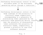
- Fig. 5 is a schematic flowchart according to some embodiments of a control method of a ray generating device of the present disclosure.
- the control method of the ray generating device includes step 100 and step 200. Step 100 and step 200 are performed synchronously according to chronological control instructions of the controller.
- chronological control is performed on the microwave power of the microwave generating device 4 through a controller 1.
- chronological control is performed on the beam loadings of the plurality of electronic beams respectively corresponding to a plurality of accelerating tubes 3 generated by the electronic beam generating device 2, such that the plurality of accelerating tubes 3 accelerate the plurality of electronic beams, respectively, to produce a plurality of rays with different energies, for example, an X-ray.
- the electronic beam generating device 2 includes: a first electronic gun 22 and a second electronic gun 24 respectively generating the first electronic beam and the second electronic beam, and a first electronic gun power source 21 and a second electronic gun power source 23 in signal connection with the controller 1 and connected with the first electronic gun 22 and the second electronic gun 24, respectively.
- step 100 includes: through the controller 1, allowing the first electronic gun power source 21 to adjust the beam loading of the first electronic beam to be a first beam loadings 2a, 2b at the first time periods t 11 and t 12 in each period T of at least one period T, and allowing the second electronic gun power source 23 to adjust the beam loading of the second electronic beam to be a second beam loading 3a at the second time period t 2 in each period T, wherein the first time periods t 11 and t 12 do not coincide with the second time period t 2 .
- At least two power output ports of the microwave circulator 5 include a first power output port b and a second power output port c, the first power output port b is allocated with a microwave signal fed from the power input port a, and the second power output port c is allocated with a microwave signal fed from the first power output port b; and the plurality of accelerating tubes 3 include: a first accelerating tube 31 connected with the first power output port b and the first electronic gun 22 and a second accelerating tube 32 connected with the second power output port c and the second electronic gun 24.
- step 200 includes: through the controller 1, allowing a microwave signal fed by the microwave generating device 4 into the power input port a of the microwave circulator 5 to include at least one first input microwave signal at the first time period, and allowing a microwave signal fed by the microwave generating device 4 into the power input port a of the microwave circulator 5 to include at least one second input microwave signal 1c at the second time period, and the power of at least one first input microwave signal is greater than that of the at least one second input microwave signal 1c.
- At least one first input microwave signal includes two first input microwave signals 1a and 1b located at different portions of the first time period (e.g., the first time period t 11 and the first time period t 12 ), and the power of the two first input microwave signals 1a and 1b is the same or different.
- the first beam loadings 2a and 2b of the first electronic beam corresponding to different portions t11 and t12 of the two first input microwave signals 1a and 1b at the first time period are the same or different.
- At least one second input microwave signal includes one second input microwave signal 1c located at the second time period t 2 . In some other embodiments, at least one second input microwave signal includes two second input microwave signals located at different portions of the second time period, and the power of the two second input microwave signals located at different portions of the second time period is the same or different, and the second beam loadings of the second electronic beam corresponding to different portions of the two second input microwave signals at the second time period are the same or different.
Landscapes
- Physics & Mathematics (AREA)
- Engineering & Computer Science (AREA)
- Plasma & Fusion (AREA)
- Spectroscopy & Molecular Physics (AREA)
- Health & Medical Sciences (AREA)
- General Health & Medical Sciences (AREA)
- Toxicology (AREA)
- Particle Accelerators (AREA)
Abstract
Description
- The present application is based on and claims priority to
Chinese Application No. 202110779750.3, filed on July 9, 2021 - The present disclosure relates to the field of accelerators, in particular to a ray generating device and a control method thereof.
- In security inspection equipment of large-scale vehicles/containers in the fields of customs, civil aviation and railway transportation, an electron linear accelerator system is mostly used as an X-ray generating device. The high-energy X-rays generated by the generating device can perform nondestructive testing on objects with different thicknesses and masses, and quickly realize effective recognition of objects to be inspected and recognition and marking of contrabands contained in the objects to be inspected without opening boxes, so as to ensure personal and property security of citizens and maintain social stability.
- In related radiation imaging field, the object to be inspected is recognized and detected mainly by utilizing an X-ray projection imaging technology. According to requirements of the application location and recognition accuracy, multiple radioactive sources are generally adopted to form multi-view radiation imaging.
- One aspect of the present disclosure provides a ray generating device, including:
- an electronic beam generating device, configured to generate a plurality of electronic beams;
- a microwave generating device, configured to generate a microwave;
- a microwave circulator, having a power input port and at least two power output ports, the power input port being connected to the microwave generating device through a waveguide structure;
- a plurality of accelerating tubes, connected to the electronic beam generating device and respectively connected to the at least two power output ports, configured to receive a plurality of electronic beams generated by the electronic beam generating device, respectively, and accelerate the plurality of electronic beams respectively through microwaves received from the at least two power output ports, so as to generate a plurality of rays having different energies, respectively; and
- a controller, in signal connection with the electronic beam generating device and the microwave generating device, configured to perform chronological control on microwave power of the microwave generating device, and chronological control on beam loadings of the electronic beams generated by the electronic beam generating device and respectively corresponding to the plurality of accelerating tubes.
- In some embodiments, the electronic beam generating device includes:
- a first electronic gun, configured to generate a first electronic beam;
- a first electronic gun power source in signal connection with the controller and connected to the first electronic gun, configured to adjust the beam loading of the first electronic beam according to a chronological control signal provided by the controller;
- a second electronic gun, configured to generate a second electronic beam; and
- a second electronic gun power source in signal connection with the controller and connected to the second electronic gun, configured to adjust a beam loading of the second electronic beam according to a chronological control signal provided by the controller,
- wherein the controller is configured to allow the first electronic gun power source to adjust the beam loading of the first electronic beam to be a first beam loading at a first time period in each period of at least one period, and to allow the second electronic gun power source to adjust the beam loading of the second electronic beam to be a second beam loading at a second time period in each period, the first time period does not coincide with the second time period.
- In some embodiments, the first beam loading is less than or equal to the second beam loading.
- In some embodiments, at least two power output ports of the microwave circulator include a first power output port and a second power output port, the first power output is allocated with a microwave signal fed from the power input port, and the second power output port is allocated with a microwave signal fed from the first power output port; and
- the plurality of accelerating tubes include:
- a first accelerating tube connected to the first power output port and the first electronic gun, configured to accelerate the first electronic beam through a first output microwave signal output by the first power output port; and
- a second accelerating tube connected to the second power output port and the second electronic gun, configured to accelerate the second electronic beam through a second output microwave signal output by the second power output port.
- In some embodiments, at least two power output ports of the microwave circulator further include a third power output port, the third power output port is allocated with a microwave signal fed from the second power output port; and the ray generating device further includes: an absorbing load connected to the third power output port, configured to absorb a microwave signal output by the third power output port.
- In some embodiments, the microwave circulator includes a four-port circulator.
- In some embodiments, the controller is configured to allow a microwave signal fed by the microwave generating device to the power input port of the microwave circulator to include at least one first input microwave signal at the first time period, and to allow the microwave signal fed by the microwave generating device to the power input port of the microwave circulator to include at least one second input microwave signal at the second time period, and power of the at least one first input microwave signal is greater than that of the at least one second input microwave signal.
- In some embodiments, the microwave generating device includes a magnetron.
- One aspect of the present disclosure provides a control method of the above-mentioned ray generating device, and the control method includes:
performing chronological control on the microwave power of the microwave generating device through the controller, and performing chronological control on the beam loadings of a plurality of electronic beams respectively corresponding to the plurality of accelerating tubes generated by the electronic beam generating device, such that the plurality of accelerating tubes accelerate the plurality of electronic beams, respectively, to generate a plurality of rays having different energies. - In some embodiments, the electronic beam generating device includes: a first electronic gun and a second electronic gun respectively generating a first electronic beam and a second electronic beam, and a first electronic gun power source and a second electronic gun power source in signal connection with the controller and connected with the first electronic gun and the second electronic gun, respectively;
- wherein the step of performing chronological control on the beam loadings of a plurality of electronic beams respectively corresponding to a plurality of accelerating tubes through a controller includes:
- through the controller, allowing the first electronic gun power source to adjust the beam loading of the first electronic beam to be a first beam loading at a first time period in each period of at least one period, and allowing the second electronic gun power source to adjust the beam loading of the second electronic beam to be a second beam loading at a second time period in each period, wherein the first time period does not coincide with the second time period.
- In some embodiments, at least two power output ports of the microwave circulator include a first power output port and a second power output port, the first power output is allocated with a microwave signal fed from the power input port, and the second power output is allocated with a microwave signal fed from the first power output port; the plurality of accelerating tubes include: a first accelerating tube connected with the first power output port and the first electronic gun and a second accelerating tube connected with the second power output port and the second electronic gun,
- wherein the step of performing chronological control on the microwave power of the microwave generating device through the controller includes:
- through the controller, allowing a microwave signal fed by the microwave generating device to the power input port of the microwave circulator to include at least one first input microwave signal at the first time period, and allowing a microwave signal fed by the microwave generating device to the power input port of the microwave circulator to include at least one second input microwave signal at the second time period, and power of at least one first input microwave signal is greater than that of at least one second input microwave signal.
- In some embodiments, the at least one first input microwave signal includes two first input microwave signals located at different portions of the first time period, the power of the two first input microwave signals is the same or different, and the first beam loadings of the first electronic beam corresponding to different portions of the two first input microwave signals at the first time period are the same or different.
- In some embodiments, the at least one second input microwave signal includes two second input microwave signals located at different portions of the second time period, the power of the two second input microwave signals is the same or different, and the second beam loadings of the second electronic beam corresponding to different portions of the two second input microwave signals at the second time period are the same or different.
- The accompanying drawings, which form part of the description, illustrate embodiments of the present disclosure and together with the description, serve to explain the principles of the present disclosure.
- The present disclosure can be more clearly understood from the following detailed descriptions with reference to the accompanying drawings, in which:
-
Fig. 1 is a structure diagram in some embodiments according to a ray generating device of the present disclosure; -
Fig. 2 is a structure diagram in some other embodiments according to a ray generating device of the present disclosure; -
Fig. 3 is a structure diagram of a four-port circulator in some embodiments according to a ray generating device of the present disclosure; -
Fig. 4 is a schematic diagram of a chronological control and ray energy output according to some embodiments of the ray generating device of the present disclosure; and -
Fig. 5 is a schematic flowchart according to some embodiments of a control method of a ray generating device of the present disclosure. - It should be understood that the dimensions of various parts shown in the accompanying drawings are not drawn according to an actual scale relationship. In addition, the same or similar reference signs indicate the same or similar components.
- Various exemplary embodiments of the present disclosure will now be described in detail with reference to the accompanying drawings. The descriptions of the exemplary embodiments are merely illustrative and are in no way intended to limit the present disclosure, and application or uses thereof. The present disclosure can be implemented in many different forms and is not limited to the embodiments described herein. These embodiments are provided, so that the present disclosure will be thorough and complete, and will fully convey the scope of the present disclosure to those skilled in the art. It should be noted that unless otherwise specified, the relative arrangement of components and steps, the composition of materials, numerical expressions and numerical values set forth in these embodiments should be interpreted as merely illustrative and not as limitative.
- Similar words of "first", "second" and the like used in the present disclosure do not indicate any order, quantity or importance, but are only used to distinguish different parts. Similar words such as "including" or "comprising" mean that the elements before the word cover the elements listed after the word, without excluding the possibility of covering other elements. "Upper", "lower", "left", "right" and the like are only used to indicate a relative positional relationship. After the absolute position of a described object changes, the relative positional relationship may also change accordingly.
- In the present disclosure, when it is described that a specific device is located between a first device and a second device, there may be an intervening device between the specific device and the first device or the second device or not. When it is described that the specific device is connected to other devices, the specific device may be directly connected to the other devices without the intervening device, and may also have the intervening device without being directly connected to the other devices.
- All terms (including technical terms or scientific terms) used in the present disclosure have the same meanings as those understood by ordinary skilled in the art to which the present disclosure belongs, unless otherwise defined particularly. It should also be understood that the terms defined in, for example, general dictionaries should be interpreted as having the meanings consistent with their meanings in the context of the related art, and should not be interpreted in an idealized or extremely formal sense unless explicitly defined herein.
- Technologies, methods and equipment known to those skilled in the related art may not be discussed in detail, but the technologies, methods and equipment should be regarded as part of the description under appropriate circumstances.
- The inventor found through researches that, a single ray source has a problem that substances which are overlapped on an image are difficult to be distinguished in terms of single-angle imaging due to a transmission imaging principle; while a multi-ray source generally requires cooperation of a plurality of groups of detectors, thereby leading to an increase of system cost and having requirements on the installation space.
- In view of this, embodiments of the present disclosure provide a ray generating device and a control method thereof, which are capable of implementing requirement of multi-energy spectrum detection of objects.
-
Fig. 1 is a structure diagram in some embodiments according to a ray generating device of the present disclosure. Refer toFig. 1 , in some embodiments, the ray generating device includes an electronicbeam generating device 2, amicrowave generating device 4, amicrowave circulator 5, a plurality of acceleratingtubes 3, and acontroller 1. - The electronic
beam generating device 2 is configured to generate a plurality of electronic beams. In some embodiments, the electronicbeam generating device 2 may cause a plurality of electronic guns to generate a plurality of electronic beams with the same or different beam loadings, respectively, by means of different high voltage amplitudes generated by a pulse modulator. - The
microwave generating device 4 is configured to generate a microwave. In some embodiments, themicrowave generating device 4 may generate varying operating currents by means of different amplitudes of voltage output from the pulse modulator, thereby generating microwave signals of different power. In some other embodiments, themicrowave generating device 4 may also generate microwave signals of different power through variations of the magnetic field intensity. - The
microwave circulator 5 has a power input port and at least two power output ports, and the power input port is connected to themicrowave generating device 4 through a waveguide structure. Themicrowave circulator 5 has isolation characteristics and power allocation characteristics, and can transmit microwave energies along a single direction. By connecting the singlemicrowave generating device 4 to the power input port of themicrowave circulator 5, microwave energies fed from the power input port can be allocated to a specific power output port, and reflected microwave energies received by that power output port can be allocated to another power output port. By utilizing such characteristic of themicrowave circulator 5 in conjunction with the chronological control of themicrowave generating device 4, it is possible to achieve microwave energy output of more than two ports through themicrowave generating device 4 as a single microwave power source. - The plurality of accelerating
tubes 3 are connected to the electronicbeam generating device 2, and connected to the at least two power output ports, respectively. The plurality of acceleratingtubes 3 can receive a plurality of electronic beams generated by the electronicbeam generating device 2, respectively, and accelerate the plurality of electronic beams respectively through the microwaves received from the at least two power output ports, so as to generate a plurality of rays having different energies, respectively. The accelerated electronic beams may generate rays, such as X-rays, by bombarding a target. - The
controller 1 is in signal connection with the electronicbeam generating device 2 and themicrowave generating device 4, and is configured to perform chronological control on microwave power of themicrowave generating device 4, and chronological control on beam loadings of the electronic beams generated by the electronicbeam generating device 2 and respectively corresponding to the plurality of acceleratingtubes 3. Through the chronological control performed by thecontroller 1 on themicrowave generating device 4 and the electronicbeam generating device 2, the plurality of acceleratingtubes 3 can respectively generate rays of different energies through a microwave power source, so as to implement the inspection requirement of multi-energy spectrum coverage of an object, and improving the wire resolution indexes of the system while ensuring the penetrability. -
Fig. 2 is a structure diagram in some other embodiments according to a ray generating device of the present disclosure.Fig. 3 is a structure diagram of a four-port circulator in some embodiments according to a ray generating device of the present disclosure. Referring toFig. 2 , in some embodiments, the electronicbeam generating device 2 includes a firstelectronic gun 22, a first electronicgun power source 21, a secondelectronic gun 24, and a second electronicgun power source 23. The firstelectronic gun 22 is configured to generate a first electronic beam. The secondelectronic gun 24 is configured to generate a second electronic beam. Each electronic gun power source and the microwave generating device may be powered by the same AC power source (e.g., 380V). - The first electronic
gun power source 21 is in signal connection with thecontroller 1 and connected to the firstelectronic gun 22, and is configured to adjust the beam loading of the first electronic beam according to a chronological control signal provided by thecontroller 1. The second electronicgun power source 23 is in signal connection with thecontroller 1 and connected to the secondelectronic gun 24, and is configured to adjust the beam loading of the second electronic beam according to a chronological control signal provided by thecontroller 1. Thecontroller 1 may adjust voltages applied to the electronic guns by sending a chronological control signal (e.g., pulse width modulation signal) to the electronic gun power sources to further adjust the beam loadings of the electronic beams. - Refer to
Fig. 2 andFig. 3 , in some embodiments, at least two power output ports of themicrowave circulator 5 include a first power output port b and a second power output port c, the first power output b is allocated with a microwave signal fed from the power input port a, and the second power output c is allocated with a microwave signal fed from the first power output port b. The microwave signal fed from the first power output port b may be a reflected microwave signal that is reflected back after being output outward from the first power output port b. - In
Fig. 2 , the plurality of acceleratingtubes 3 include a first acceleratingtube 31 and a second acceleratingtube 32. The first acceleratingtube 31 is connected to the first power output port b and the firstelectronic gun 22, and is configured to accelerate the first electronic beam through a first output microwave signal output by the first power output port b. The second acceleratingtube 32 is connected to the second power output port c and the secondelectronic gun 24, and is configured to accelerate the second electronic beam through a second output microwave signal output by the second power output port c. The accelerated first and second electronic beams may generate X-rays of different energies by bombarding a target. - In some other embodiments, the electronic beam generating device may include more than three electronic guns and corresponding electronic gun power sources thereof, and the ray generating device includes more than three accelerating tubes. Accordingly, the accelerating tubes are connected to more than three power output ports of the microwave circulator, respectively, so as to realize output of more types of ray energies through the chronological control of the controller and implement the multi-energy spectrum inspection requirements and multi-viewpoint scanning requirements to the objects.
- Referring to
Fig. 2 , in some embodiments, at least two power output ports of themicrowave circulator 5 further include a third power output port d. The third power output port d is allocated with a microwave signal fed from the second power output port c. The microwave signal fed from the second power output port c may be a reflected microwave signal that is reflected back after being output outward from the second power output port c. The ray generating device may further include an absorbingload 6 connected to the third power output port d. The absorbing load can absorb the microwave signal output from the third power output port d to realize an isolation effect to prevent the microwave signal from returning to the power input port of the microwave circulator. - Referring to
Fig. 3 , in some embodiments, themicrowave circulator 5 includes a four-port circulator 51. The four-port circulator 51 has four ports, which are a power input port a, a first power output port b, a second power output port c and a third power output port d in the power transmission sequence, respectively, that is, the power transmission rule of the four-port circulator 51 is a→b→c→d. In some other embodiments, themicrowave circulator 5 may further include a combination structure of a plurality of three-port circulators and four-port circulators connected in series. -
Fig. 3 illustrates the structure of a ferrite four-port circulator. The four-port circulator is a coupled device including a dual-T joint, a nonreciprocal phase shifter based on ferrite field-displacement effect, and a 3dB coupler. During the operation of the ray generating device, an electromagnetic wave of which the amplitude is E0 is fed from the power input port a. Due to the dual-T (H branch) characteristic, electromagnetic waves with equal amplitude of E0/(2^(1/2)) and equal phase will be output from waveguides I and II at side A-B. The nonreciprocal phase shifter can allow phase of the electromagnetic wave in the waveguide I to be 90° ahead relative to that in the waveguide II when the electromagnetic wave is forwardly transmitted from side A-B to side C-D (and conversely, the phase in the waveguide II is 90° ahead relative to the phase in the waveguide I if it is reversely transmitted from side C-D to side A-B), and the 3dB coupler from side C-D to a location between the first power output port b and the third power output port d can cause the microwave power in the waveguides I and II to be equally divided to the first power output port b and the third power output port d, respectively, but the phase shift is increased by 90° during the coupling transmission, so that all microwave power output from the waveguide I and the waveguide II to the first power output port b and the third power output port d, respectively, is output from the first power output port b, but is not output at the third power output port d. - Similarly, the microwave power input from the first power output port b is allocated to the second power output port c for output, and the microwave power input from the second power output port c is allocated to the third power output port d for output. Accordingly, the reflected microwave input from the first power output port b is allocated to the second power output port c for output, and the reflected wave from the second power output port c will be transmitted to the third power output port d and absorbed by the absorbing load.
- In some embodiments, the chronological control by the
controller 1 causes the first accelerating tube connected to the first power output port b to obtain larger power and energy to output at least one type of X-rays with a higher energy, for example, X-rays with output energies of 6MeV and 3MeV; and the chronological control by thecontroller 1 causes the second accelerating tube connected to the second power output port c to obtain smaller power and energy to output at least one type of X-rays with a lower energy, such as X-rays with output energies of 0.5 to 1MeV. In this way, the effect of power allocation is achieved by differences of the microwave power output from different power output ports of the microwave circulator, and accelerating tubes with different energies can be driven by utilizing the power allocation characteristic of the microwave circulator, so as to implement various inspection requirements. -
Fig. 4 is a schematic diagram of chronological control and ray energy output according to some embodiments of the ray generating device of the present disclosure. Please referring toFig. 4 , in some embodiments, thecontroller 1 is configured to cause the first electronicgun power source 21 to adjust the beam loading of the first electronic beam to be the first beam loading at the first time period in each period T of at least one period T, and cause the second electronicgun power source 23 to adjust the beam loading of the second electronic beam to be the second beam loading at the second time period in each period T, and the first time period does not coincide with the second time period. - The
controller 1 is further configured to cause the microwave signal fed by themicrowave generating device 4 into the power input port a of themicrowave circulator 5 to include at least one first input microwave signal at the first time period, and cause the microwave signal fed by themicrowave generating device 4 into the power input port a of themicrowave circulator 5 to include at least one second input microwave signal at the second time period, and the power of at least one first input microwave signal is greater than the power of at least one second input microwave signal. - Sequential control instructions sent by the
above controller 1 achieves alternate operating mode of the first acceleratingtube 31 and the second acceleratingtube 32, and the first acceleratingtube 31 and the second acceleratingtube 32 can generate X-rays of different energies at different time periods of each period T in cooperation with power distribution effects of themicrowave circulator 5. In some embodiments, the X-rays generated by the first acceleratingtube 31 and the second acceleratingtube 32 can be arranged to irradiate towards different directions, to achieve multi-view radiation imaging. - In
Fig. 4 , themagnetron 41 inputs three pulsed microwave power of different amplitudes in sequence to the power input port a of the four-port circulator 51 in each period T, that is, the highestpulsed microwave power 1a is input at the first time period t11, the second highestpulsed microwave power 1b is input at the first time period t12, and the lowerpulsed microwave power 1c is input at the second time period t2. Corresponding to the first time periods t11 and t12, the first electronic beam is configured with the first beam loadings 2a and 2b, respectively. Corresponding to the second time period t2, the second electronic beam is configured with the second beam loading 3a. In some embodiments, the first beam loading is less than or equal to the second beam loading, for example, inFig. 4 , the second beam loading 3a is approximately equal to the first beam loading 2b and is greater than the first beam loading 2a. - The formula of the beam loading effect can be represented as follows: E=(A*P)^0.5-B*I. E is the energy of the accelerated electronic beam, I is the intensity of the accelerated electronic beam (that is, the beam loading), P is the pulsed microwave power fed into the accelerating tube, and A and B are predetermined constants. According to the beam loading effect, high-energy electronic beams having different energies will be obtained when different electronic beams are accelerated. Referring to
Fig. 4 , the greater the beam loading, the smaller the power of the microwaves fed into the accelerating tube, and the smaller the energy obtained when the electronic beam is accelerated in the accelerating tube, otherwise, the smaller the beam loading, the larger the power of the microwaves fed into the accelerating tube, and the greater the energy obtained when the electronic beam is accelerated in the accelerating tube. - At the first time periods t11 and t12, the first electronic beam is configured with first beam loadings 2a and 2b. The
pulsed microwave powers tube 31 through the first power output port b of the four-port circulator 51. Since thepulsed microwave power 1a is greater than thepulsed microwave power 1b, and the first beam loading 2a is less than the second beam loading 2b, the first accelerating tube respectively generates X-rays having two different energies, higher and lower energies 4a and 4b (for example, 6 MeV and 3 MeV) at the first time period t11 and the first time period t12. - Since the microwave energy fed into the first accelerating
tube 31 is used for acceleration of the first electronic beam, fewer reflected microwaves are returned from the first power output port b. While at the first time period, the second electronic beam is not configured with a beam loading, therefore, reflected microwaves entering the first power output port b are allocated to the second power output port c, and are reflected back to the second power output port c. The reflected microwaves entering the second power output port c are again allocated to the third power output port d, and are absorbed by the absorbing loads connected to the third power output port d. - The
pulsed microwave power 1c input from the power input port a at the second time period t2 is fed into the first acceleratingtube 31 through the first power output port b of the four-port circulator 51. Since the first electronic beam is not configured with a beam loading at the second time period t2, more microwave energies entering from the first power output port b into the first acceleratingtube 31 are reflected back to the first power output port b. Reflected microwaves entering the first power output port b are allocated to the second power output port c, and the second electronic beam at the second time period t2 is configured with a second beam loading 3a, such that at the second time period t2, the second acceleratingtube 32 generates an X-ray having a lower energy 4c (for example, 0.5-1 MeV) than the energies 4a, 4b of the X-rays generated by the first acceleratingtube 31. - Through each embodiment of the above ray generating device of the present disclosure, while fully utilizing operating characteristics of the output power of each port of the microwave circulator, a single microwave power source is matched with the beam loading of an electronic beam generating device, to achieve output of multiple different ray energies, and satisfy the ray scanning requirements of different operating environments. Through chronological control of a controller, diversified ray energy output can be achieved, and stability of multiple-stage energy output can be ensured.
-
Fig. 5 is a schematic flowchart according to some embodiments of a control method of a ray generating device of the present disclosure. Referring toFig. 5 , based on the embodiment of the above ray generating device, in some embodiments, the control method of the ray generating device includesstep 100 andstep 200. Step 100 and step 200 are performed synchronously according to chronological control instructions of the controller. - In the
step 100, chronological control is performed on the microwave power of themicrowave generating device 4 through acontroller 1. In thestep 200, chronological control is performed on the beam loadings of the plurality of electronic beams respectively corresponding to a plurality of acceleratingtubes 3 generated by the electronicbeam generating device 2, such that the plurality of acceleratingtubes 3 accelerate the plurality of electronic beams, respectively, to produce a plurality of rays with different energies, for example, an X-ray. - Referring to
Fig. 2 , in some embodiments, the electronicbeam generating device 2 includes: a firstelectronic gun 22 and a secondelectronic gun 24 respectively generating the first electronic beam and the second electronic beam, and a first electronicgun power source 21 and a second electronicgun power source 23 in signal connection with thecontroller 1 and connected with the firstelectronic gun 22 and the secondelectronic gun 24, respectively. Correspondingly,step 100 includes: through thecontroller 1, allowing the first electronicgun power source 21 to adjust the beam loading of the first electronic beam to be a first beam loadings 2a, 2b at the first time periods t11 and t12 in each period T of at least one period T, and allowing the second electronicgun power source 23 to adjust the beam loading of the second electronic beam to be a second beam loading 3a at the second time period t2 in each period T, wherein the first time periods t11 and t12 do not coincide with the second time period t2. - Referring to
Fig. 2 , in some embodiments, at least two power output ports of themicrowave circulator 5 include a first power output port b and a second power output port c, the first power output port b is allocated with a microwave signal fed from the power input port a, and the second power output port c is allocated with a microwave signal fed from the first power output port b; and the plurality of acceleratingtubes 3 include: a first acceleratingtube 31 connected with the first power output port b and the firstelectronic gun 22 and a second acceleratingtube 32 connected with the second power output port c and the secondelectronic gun 24. - Correspondingly,
step 200 includes: through thecontroller 1, allowing a microwave signal fed by themicrowave generating device 4 into the power input port a of themicrowave circulator 5 to include at least one first input microwave signal at the first time period, and allowing a microwave signal fed by themicrowave generating device 4 into the power input port a of themicrowave circulator 5 to include at least one secondinput microwave signal 1c at the second time period, and the power of at least one first input microwave signal is greater than that of the at least one secondinput microwave signal 1c. - In some embodiments, at least one first input microwave signal includes two first
input microwave signals input microwave signals input microwave signals - In some embodiments, at least one second input microwave signal includes one second
input microwave signal 1c located at the second time period t2. In some other embodiments, at least one second input microwave signal includes two second input microwave signals located at different portions of the second time period, and the power of the two second input microwave signals located at different portions of the second time period is the same or different, and the second beam loadings of the second electronic beam corresponding to different portions of the two second input microwave signals at the second time period are the same or different. - Multiple embodiments in the specification are described in a progressive manner, with different emphasis on each embodiment, and the same or similar parts of various embodiments can be referred by each other. As for the method embodiments, due to the correspondence between their entirety and the involved steps and the content in the apparatus embodiments, the description is relatively simple. Please refer to partial illustration of the apparatus embodiments for related details.
- So far, various embodiments of the present disclosure have been described in detail. In order to avoid obscuring concepts of the present disclosure, some details that are well known in the art have not been described. Those skilled in the art can fully understand how to implement the technical solutions disclosed here according to the above descriptions.
- Although some specific embodiments of the present disclosure have been described in detail through examples, it should be understood by those skilled in the art that the above examples are only for illustration and are not intended to limit the scope of the present disclosure. Those skilled in the art should understand that the above embodiments can be modified or some technical features can be replaced by equivalents without departing from the scope and spirit of the present disclosure. The scope of the present disclosure is defined by appended claims.
Claims (13)
- A ray generating device, comprising:an electronic beam generating device (2), configured to generate a plurality of electronic beams;a microwave generating device (4), configured to generate a microwave;a microwave circulator (5), having a power input port (a) and at least two power output ports, the power input port (a) being connected to the microwave generating device (4) through a waveguide structure;a plurality of accelerating tubes (3), connected to the electronic beam generating device (2) and respectively connected to the at least two power output ports, configured to receive a plurality of electronic beams generated by the electronic beam generating device (2), respectively, and accelerate the plurality of electronic beams respectively through microwaves received from the at least two power output ports, so as to generate a plurality of rays having different energies, respectively; anda controller (1), in signal connection with the electronic beam generating device (2) and the microwave generating device (4), configured to perform chronological control on microwave power of the microwave generating device (4), and chronological control on beam loadings of the electronic beams generated by the electronic beam generating device (2) and respectively corresponding to the plurality of accelerating tubes (3).
- The ray generating device according to claim 1, wherein the electronic beam generating device (2) comprises:a first electronic gun (22), configured to generate a first electronic beam;a first electronic gun power source (21) in signal connection with the controller (1) and connected to the first electronic gun (22), configured to adjust the beam loading of the first electronic beam according to a chronological control signal provided by the controller (1);a second electronic gun (24), configured to generate a second electronic beam; anda second electronic gun power source (23) in signal connection with the controller (1) and connected to the second electronic gun (24), configured to adjust a beam loading of the second electronic beam according to a chronological control signal provided by the controller (1),wherein the controller (1) is configured to allow the first electronic gun power source (21) to adjust the beam loading of the first electronic beam to be a first beam loading (2a; 2b) at a first time period (t11; t12) in each period (T) of at least one period (T), and to allow the second electronic gun power source (23) to adjust the beam loading of the second electronic beam to be a second beam loading (3a) at a second time period (t2) in each period (T), the first time period (tn; t12) does not coincide with the second time period (t2).
- The ray generating device according to claim 2, wherein the first beam loading (2a; 2b) is less than or equal to the second beam loading (3a).
- The ray generating device according to claim 2, wherein at least two power output ports of the microwave circulator (5) comprise a first power output port (b) and a second power output port (c), the first power output is allocated with a microwave signal fed from the power input port (a), and the second power output port (c) is allocated with a microwave signal fed from the first power output port (b); and
the plurality of accelerating tubes (3) comprise:a first accelerating tube (31) connected to the first power output port (b) and the first electronic gun (22), configured to accelerate the first electronic beam through a first output microwave signal output by the first power output port (b); anda second accelerating tube (32) connected to the second power output port (c) and the second electronic gun (24), configured to accelerate the second electronic beam through a second output microwave signal output by the second power output port (c). - The ray generating device according to claim 4, wherein at least two power output ports of the microwave circulator (5) further comprise a third power output port (d), the third power output port (d) is allocated with a microwave signal fed from the second power output port (c); and the ray generating device further comprises: an absorbing load (6) connected to the third power output port (d), configured to absorb a microwave signal output by the third power output port (d).
- The ray generating device according to claim 5, wherein the microwave circulator (5) comprises a four-port circulator (51).
- The ray generating device according to claim 4, wherein the controller (1) is configured to allow a microwave signal fed by the microwave generating device (4) to the power input port (a) of the microwave circulator (5) to comprise at least one first input microwave signal (1a; 1b) at the first time period (t11; t12), and to allow the microwave signal fed by the microwave generating device (4) to the power input port (a) of the microwave circulator (5) to comprise at least one second input microwave signal (1c) at the second time period (t2), and power of the at least one first input microwave signal (1a; 1b) is greater than that of the at least one second input microwave signal (1c).
- The ray generating device according to claim 1, wherein the microwave generating device (4) comprises a magnetron (41).
- A control method of the above ray generating device according to any one of claims 1-8, comprising:performing chronological control on the microwave power of the microwave generating device (4) through the controller (1), and performing chronological control on the beam loadings of a plurality of electronic beams respectively corresponding to the plurality of accelerating tubes (3) generated by the electronic beam generating device (2), such that the plurality of accelerating tubes (3) accelerate the plurality of electronic beams, respectively, to generate a plurality of rays having different energies.
- The control method according to claim 9, wherein the electronic beam generating device (2) comprises: a first electronic gun (22) and a second electronic gun (24) respectively generating a first electronic beam and a second electronic beam, and a first electronic gun power source (21) and a second electronic gun power source (23) in signal connection with the controller (1) and connected with the first electronic gun (22) and the second electronic gun (24), respectively;
wherein the step of performing chronological control on the beam loadings of a plurality of electronic beams respectively corresponding to a plurality of accelerating tubes (3) through a controller (1) comprises:through the controller (1), allowing the first electronic gun power source (21) to adjust the beam loading of the first electronic beam to be a first beam loading (2a; 2b) at a first time period (tn; t12) in each period (T) of at least one period (T), and allowing the second electronic gun power source (23) to adjust the beam loading of the second electronic beam to be a second beam loading (3a) at a second time period (t2) in each period (T), wherein the first time period (tn; t12) does not coincide with the second time period (t2). - The control method according to claim 10, wherein at least two power output ports of the microwave circulator (5) comprise a first power output port (b) and a second power output port (c), the first power output is allocated with a microwave signal fed from the power input port (a), and the second power output is allocated with a microwave signal fed from the first power output port (b); the plurality of accelerating tubes (3) comprise: a first accelerating tube (31) connected with the first power output port (b) and the first electronic gun (22) and a second accelerating tube (32) connected with the second power output port (c) and the second electronic gun (24),
wherein the step of performing chronological control on the microwave power of the microwave generating device (4) through the controller (1) comprises:through the controller (1), allowing a microwave signal fed by the microwave generating device (4) into the power input port (a) of the microwave circulator (5) to comprise at least one first input microwave signal (1a; 1b) at the first time period (tn; t12), and allowing a microwave signal fed by the microwave generating device (4) into the power input port (a) of the microwave circulator (5) to comprise at least one second input microwave signal (1c) at the second time period (t2), and power of at least one first input microwave signal (1a; 1b) is greater than that of at least one second input microwave signal (1c). - The control method according to claim 11, wherein the at least one first input microwave signal (1a; 1b) comprises two first input microwave signals (1a; 1b) located at different portions of the first time period (tn; t12), the power of the two first input microwave signals (1a; 1b) is the same or different, and the first beam loadings (2a; 2b) of the first electronic beam corresponding to different portions of the two first input microwave signals (1a; 1b) at the first time period (tn; t12) are the same or different.
- The control method according to claim 11, wherein the at least one second input microwave signal (1c) comprises two second input microwave signals (1c) located at different portions of the second time period (t2), the power of the two second input microwave signals (1c) is the same or different, and the second beam loadings (3a) of the second electronic beam corresponding to different portions of the two second input microwave signals (1c) at the second time period (t2) are the same or different.
Applications Claiming Priority (2)
| Application Number | Priority Date | Filing Date | Title |
|---|---|---|---|
| CN202110779750.3A CN113329552A (en) | 2021-07-09 | 2021-07-09 | Radiation generating apparatus and control method thereof |
| PCT/CN2022/103769 WO2023280130A1 (en) | 2021-07-09 | 2022-07-05 | Ray generating device and control method thereof |
Publications (2)
| Publication Number | Publication Date |
|---|---|
| EP4369869A1 true EP4369869A1 (en) | 2024-05-15 |
| EP4369869A4 EP4369869A4 (en) | 2025-07-09 |
Family
ID=77426028
Family Applications (1)
| Application Number | Title | Priority Date | Filing Date |
|---|---|---|---|
| EP22836881.7A Pending EP4369869A4 (en) | 2021-07-09 | 2022-07-05 | Beam generation device and control method therefor |
Country Status (5)
| Country | Link |
|---|---|
| US (1) | US12464632B2 (en) |
| EP (1) | EP4369869A4 (en) |
| JP (1) | JP7624134B2 (en) |
| CN (2) | CN113329552A (en) |
| WO (1) | WO2023280130A1 (en) |
Families Citing this family (7)
| Publication number | Priority date | Publication date | Assignee | Title |
|---|---|---|---|---|
| CN113329552A (en) | 2021-07-09 | 2021-08-31 | 清华大学 | Radiation generating apparatus and control method thereof |
| CN113238293B (en) * | 2021-07-09 | 2021-11-02 | 同方威视技术股份有限公司 | Inspection system and method |
| CN113281821B (en) * | 2021-07-09 | 2023-10-13 | 同方威视技术股份有限公司 | Checking systems and methods |
| CN113238297B (en) * | 2021-07-09 | 2021-11-02 | 同方威视技术股份有限公司 | Radiation inspection system and method |
| CN115802579B (en) * | 2022-12-15 | 2026-07-21 | 中玖闪光医疗科技有限公司 | Ray generation device, use method and application |
| CN115811825A (en) * | 2022-12-15 | 2023-03-17 | 中国工程物理研究院应用电子学研究所 | A radiation generating device for time-division multiplexing of microwave sources, its use method and application |
| CN119743883B (en) * | 2025-03-04 | 2025-07-22 | 中国科学院近代物理研究所 | A linear accelerator based on high gradient traveling wave acceleration structure |
Family Cites Families (29)
| Publication number | Priority date | Publication date | Assignee | Title |
|---|---|---|---|---|
| US4801848A (en) | 1987-05-11 | 1989-01-31 | Quantum Diagnostics Ltd. | Tunable broadband source in millimeter wavelength range of spectrum |
| US6734428B2 (en) | 2000-02-19 | 2004-05-11 | Multibeam Systems, Inc. | Multi-beam multi-column electron beam inspection system |
| US6844689B1 (en) * | 2003-08-29 | 2005-01-18 | Mevex Corporation | Multiple beam linear accelerator system |
| CN101076218B (en) | 2006-05-19 | 2011-05-11 | 清华大学 | Apparatus and method for generating different-energy X-ray and system for discriminating materials |
| CN2917188Y (en) | 2006-05-19 | 2007-06-27 | 清华大学 | Equipment for producing X-ray with different energy and material recognition system |
| CN200987235Y (en) | 2006-10-11 | 2007-12-05 | 清华大学 | Multi-energy Frequency Doubling Particle Accelerator |
| CN101163372B (en) * | 2006-10-11 | 2010-05-12 | 清华大学 | Multi-energy frequency doubling particle accelerator and method thereof |
| GB2483830C (en) | 2009-07-13 | 2017-04-26 | Rapiscan Systems Inc | Four-sided imaging system and method for detecting of contraband |
| WO2011091070A2 (en) | 2010-01-19 | 2011-07-28 | Rapiscan Systems, Inc. | Multi-view cargo scanner |
| CA2836972A1 (en) * | 2012-12-14 | 2014-06-14 | Apollo Microwaves, Ltd. | Non-reciprocal gyromagnetic phase shift devices using multiple ferrite-containing slabs |
| CN203192747U (en) | 2012-12-27 | 2013-09-11 | 清华大学 | Equipment capable of generating distributed X rays |
| CN103906340B (en) | 2012-12-28 | 2017-04-12 | 清华大学 | Standing wave electron linear accelerator device and method thereof |
| CN104244561A (en) * | 2013-06-21 | 2014-12-24 | 同方威视技术股份有限公司 | Standing wave electron linear accelerator and container/vehicle inspection system |
| SG11201509733PA (en) | 2013-11-14 | 2016-05-30 | Univ Tsinghua | Multiple-power multiple-dosage accelerators, rapid examination systems and rapid examination methods thereof |
| US11083074B2 (en) * | 2014-02-27 | 2021-08-03 | ETM Electromatic, Inc. | Scanning linear accelerator system having stable pulsing at multiple energies and doses |
| US9622333B2 (en) | 2014-02-27 | 2017-04-11 | Etm Electromatic, Inc | Linear accelerator system with stable interleaved and intermittent pulsing |
| US9380695B2 (en) * | 2014-06-04 | 2016-06-28 | The Board Of Trustees Of The Leland Stanford Junior University | Traveling wave linear accelerator with RF power flow outside of accelerating cavities |
| CN104188679B (en) | 2014-09-25 | 2016-08-17 | 山东新华医疗器械股份有限公司 | A kind of homology two-beam medical accelerator |
| CN106455288A (en) | 2016-10-28 | 2017-02-22 | 中广核中科海维科技发展有限公司 | An Energy Adjustable Electron Linear Accelerator |
| CN206237663U (en) | 2016-10-28 | 2017-06-09 | 中广核中科海维科技发展有限公司 | An Energy Adjustable Electron Linear Accelerator with Adjustable Power Divider |
| CN108392741B (en) | 2018-04-04 | 2024-03-29 | 西安大医集团股份有限公司 | Microwave power control device and radiotherapy equipment |
| CN208509358U (en) | 2018-07-26 | 2019-02-15 | 中国人民解放军96630部队 | A kind of microwave power delivery system and industry CT detection device |
| EP3861836A4 (en) | 2018-10-03 | 2022-06-29 | Varex Imaging Corporation | Multiple head linear accelerator system |
| CN209676567U (en) * | 2018-10-25 | 2019-11-22 | 苏州雷泰医疗科技有限公司 | An accelerator therapy device |
| CN112243310B (en) * | 2019-07-16 | 2022-04-22 | 清华大学 | Multi-ray source accelerator and inspection method |
| US12036422B2 (en) * | 2019-11-11 | 2024-07-16 | Siemens Healthineers International Ag | Expansion of search space for multicriteria optimization in radiation treatment planning |
| WO2021108375A1 (en) * | 2019-11-27 | 2021-06-03 | Intraop Medical Corporation | Electron beam radiation system with advanced applicator coupling system having integrated distance detection and target illumination |
| GB202006503D0 (en) * | 2020-05-01 | 2020-06-17 | Elekta ltd | Waveguide for a liner accelerator |
| CN113329552A (en) | 2021-07-09 | 2021-08-31 | 清华大学 | Radiation generating apparatus and control method thereof |
-
2021
- 2021-07-09 CN CN202110779750.3A patent/CN113329552A/en active Pending
- 2021-07-09 CN CN202511851507.2A patent/CN121619722A/en active Pending
-
2022
- 2022-07-05 US US18/575,277 patent/US12464632B2/en active Active
- 2022-07-05 EP EP22836881.7A patent/EP4369869A4/en active Pending
- 2022-07-05 JP JP2023580688A patent/JP7624134B2/en active Active
- 2022-07-05 WO PCT/CN2022/103769 patent/WO2023280130A1/en not_active Ceased
Also Published As
| Publication number | Publication date |
|---|---|
| US20240334585A1 (en) | 2024-10-03 |
| EP4369869A4 (en) | 2025-07-09 |
| JP2024525032A (en) | 2024-07-09 |
| JP7624134B2 (en) | 2025-01-30 |
| CN121619722A (en) | 2026-03-06 |
| US12464632B2 (en) | 2025-11-04 |
| CN113329552A (en) | 2021-08-31 |
| WO2023280130A1 (en) | 2023-01-12 |
Similar Documents
| Publication | Publication Date | Title |
|---|---|---|
| US12464632B2 (en) | Ray generating device and control method thereof | |
| EP4369061A1 (en) | Inspection system and method | |
| US20240319114A1 (en) | Inspection system and method | |
| US7884559B2 (en) | Multi-energy frequency-multiplying particle accelerator and method thereof | |
| US7646851B2 (en) | Device and method for generating X-rays having different energy levels and material discrimination system | |
| EP4369052A1 (en) | Radiation inspection system and method | |
| EP2983012B1 (en) | Multiple-energy multiple-dosage accelerator, rapid examination system having the accelerator and corresponding rapid examination method | |
| EP4369054A1 (en) | Inspection system and method | |
| Garnett | Overview of accelerators with potential use in homeland security | |
| RU2246719C1 (en) | Method and device for irradiating conversion target with accelerated electrons current pulses | |
| Mistry et al. | RF sub-systems for cargo and vehicle inspection | |
| CN121751456A (en) | Multi-level radiation generator and radiation imaging apparatus | |
| CN2917188Y (en) | Equipment for producing X-ray with different energy and material recognition system | |
| Mishin et al. | Portable 2.5 MeV X-Band Linear Accelerator Structure | |
| US20250331095A1 (en) | Linear accelerator system | |
| Cha et al. | Advanced Automatic Frequency Control System for a Dual Energy S-band RF Electron Linear Accelerator | |
| RU33230U1 (en) | Device for irradiating a conversion target with current pulses of accelerated electrons | |
| French | Use of dielectric material in muon accelerator RF cavities | |
| Kim et al. | 30 kW SSA Test for the KOMAC MEBT | |
| Blackburn | CBRNE Long Stand-off Detection |
Legal Events
| Date | Code | Title | Description |
|---|---|---|---|
| STAA | Information on the status of an ep patent application or granted ep patent |
Free format text: STATUS: THE INTERNATIONAL PUBLICATION HAS BEEN MADE |
|
| PUAI | Public reference made under article 153(3) epc to a published international application that has entered the european phase |
Free format text: ORIGINAL CODE: 0009012 |
|
| STAA | Information on the status of an ep patent application or granted ep patent |
Free format text: STATUS: REQUEST FOR EXAMINATION WAS MADE |
|
| 17P | Request for examination filed |
Effective date: 20231228 |
|
| AK | Designated contracting states |
Kind code of ref document: A1 Designated state(s): AL AT BE BG CH CY CZ DE DK EE ES FI FR GB GR HR HU IE IS IT LI LT LU LV MC MK MT NL NO PL PT RO RS SE SI SK SM TR |
|
| DAV | Request for validation of the european patent (deleted) | ||
| DAX | Request for extension of the european patent (deleted) | ||
| A4 | Supplementary search report drawn up and despatched |
Effective date: 20250612 |
|
| RIC1 | Information provided on ipc code assigned before grant |
Ipc: H05H 7/02 20060101ALI20250605BHEP Ipc: H05H 9/04 20060101ALI20250605BHEP Ipc: G01V 5/00 20240101ALI20250605BHEP Ipc: H05G 1/46 20060101ALI20250605BHEP Ipc: H05G 1/08 20060101AFI20250605BHEP |