EP4369527A1 - Cable assembly and camera - Google Patents
Cable assembly and camera Download PDFInfo
- Publication number
- EP4369527A1 EP4369527A1 EP22836609.2A EP22836609A EP4369527A1 EP 4369527 A1 EP4369527 A1 EP 4369527A1 EP 22836609 A EP22836609 A EP 22836609A EP 4369527 A1 EP4369527 A1 EP 4369527A1
- Authority
- EP
- European Patent Office
- Prior art keywords
- connecting portion
- cable assembly
- mounting base
- cable
- insertion portion
- Prior art date
- Legal status (The legal status is an assumption and is not a legal conclusion. Google has not performed a legal analysis and makes no representation as to the accuracy of the status listed.)
- Granted
Links
Images




Classifications
-
- H—ELECTRICITY
- H02—GENERATION; CONVERSION OR DISTRIBUTION OF ELECTRIC POWER
- H02G—INSTALLATION OF ELECTRIC CABLES OR LINES, OR OF COMBINED OPTICAL AND ELECTRIC CABLES OR LINES
- H02G3/00—Installations of electric cables or lines or protective tubing therefor in or on buildings, equivalent structures or vehicles
- H02G3/02—Details
- H02G3/06—Joints for connecting lengths of protective tubing or channels, to each other or to casings, e.g. to distribution boxes; Ensuring electrical continuity in the joint
- H02G3/0616—Joints for connecting tubing to casing
- H02G3/0625—Joints for connecting tubing to casing with means for preventing disengagement of conductors
- H02G3/0675—Joints for connecting tubing to casing with means for preventing disengagement of conductors with bolts operating in a direction parallel to the conductors
-
- H—ELECTRICITY
- H01—ELECTRIC ELEMENTS
- H01R—ELECTRICALLY-CONDUCTIVE CONNECTIONS; STRUCTURAL ASSOCIATIONS OF A PLURALITY OF MUTUALLY-INSULATED ELECTRICAL CONNECTING ELEMENTS; COUPLING DEVICES; CURRENT COLLECTORS
- H01R13/00—Details of coupling devices of the kinds covered by groups H01R12/70 or H01R24/00 - H01R33/00
- H01R13/62—Means for facilitating engagement or disengagement of coupling parts or for holding them in engagement
-
- G—PHYSICS
- G03—PHOTOGRAPHY; CINEMATOGRAPHY; ANALOGOUS TECHNIQUES USING WAVES OTHER THAN OPTICAL WAVES; ELECTROGRAPHY; HOLOGRAPHY
- G03B—APPARATUS OR ARRANGEMENTS FOR TAKING PHOTOGRAPHS OR FOR PROJECTING OR VIEWING THEM; APPARATUS OR ARRANGEMENTS EMPLOYING ANALOGOUS TECHNIQUES USING WAVES OTHER THAN OPTICAL WAVES; ACCESSORIES THEREFOR
- G03B17/00—Details of cameras or camera bodies; Accessories therefor
- G03B17/02—Bodies
-
- H—ELECTRICITY
- H01—ELECTRIC ELEMENTS
- H01R—ELECTRICALLY-CONDUCTIVE CONNECTIONS; STRUCTURAL ASSOCIATIONS OF A PLURALITY OF MUTUALLY-INSULATED ELECTRICAL CONNECTING ELEMENTS; COUPLING DEVICES; CURRENT COLLECTORS
- H01R13/00—Details of coupling devices of the kinds covered by groups H01R12/70 or H01R24/00 - H01R33/00
- H01R13/46—Bases; Cases
- H01R13/52—Dustproof, splashproof, drip-proof, waterproof, or flameproof cases
- H01R13/5205—Sealing means between cable and housing, e.g. grommet
-
- H—ELECTRICITY
- H01—ELECTRIC ELEMENTS
- H01R—ELECTRICALLY-CONDUCTIVE CONNECTIONS; STRUCTURAL ASSOCIATIONS OF A PLURALITY OF MUTUALLY-INSULATED ELECTRICAL CONNECTING ELEMENTS; COUPLING DEVICES; CURRENT COLLECTORS
- H01R13/00—Details of coupling devices of the kinds covered by groups H01R12/70 or H01R24/00 - H01R33/00
- H01R13/46—Bases; Cases
- H01R13/52—Dustproof, splashproof, drip-proof, waterproof, or flameproof cases
- H01R13/5216—Dustproof, splashproof, drip-proof, waterproof, or flameproof cases characterised by the sealing material, e.g. gels or resins
-
- H—ELECTRICITY
- H01—ELECTRIC ELEMENTS
- H01R—ELECTRICALLY-CONDUCTIVE CONNECTIONS; STRUCTURAL ASSOCIATIONS OF A PLURALITY OF MUTUALLY-INSULATED ELECTRICAL CONNECTING ELEMENTS; COUPLING DEVICES; CURRENT COLLECTORS
- H01R13/00—Details of coupling devices of the kinds covered by groups H01R12/70 or H01R24/00 - H01R33/00
- H01R13/62—Means for facilitating engagement or disengagement of coupling parts or for holding them in engagement
- H01R13/629—Additional means for facilitating engagement or disengagement of coupling parts, e.g. aligning or guiding means, levers, gas pressure electrical locking indicators, manufacturing tolerances
- H01R13/631—Additional means for facilitating engagement or disengagement of coupling parts, e.g. aligning or guiding means, levers, gas pressure electrical locking indicators, manufacturing tolerances for engagement only
Definitions
- the present disclosure relates to the technical field of core wire waterproof design, and in particular to a cable assembly and a camera.
- a first aspect of the embodiments of the present disclosure provides a cable assembly, for being assembled on a mounting base, the cable assembly includes: a core wire; and a SR connector, the SR connector includes an insertion portion and a connecting portion, wherein the insertion portion includes a through insertion hole, the core wire is passed through the insertion hole, and both ends of the core wire extend to outside the insertion hole, the core wire and the insertion portion are integrally provided, the connecting portion is provided outside the insertion portion for connecting with the mounting base, the connecting portion and the insertion portion are integrally provided, and a material hardness of the connecting portion is greater than a material hardness of the insertion portion.
- the insertion portion and the connecting portion are integrally provided, and the insertion portion and the core wire are integrally provided, a material hardness of the connecting portion is greater than a material hardness of the insertion portion, and the connecting portion has higher strength, thereby making it easier to maintain relative fixation with the mounting base, and while eliminating the need for the use of fasteners such as locking elements and pressing rings, thus simplifying structure and reducing material costs and installation costs.
- the cable assembly according to the embodiments of the present disclosure also includes the following additional technical features:
- the insertion portion includes a soft colloid
- the connecting portion includes a hard colloid.
- the insertion portion includes a groove
- the connecting portion includes a connecting body and a bonding wall protruding from the connecting body, the bonding wall extending into the groove, and bonding with an inner wall of the groove.
- the insertion portion includes an insertion body and a protrusion portion protruding from an outer wall of the insertion body, and the insertion body is provided with the insertion hole, the protrusion portion is provided with the groove; and/or the groove is an annular groove, and the bonding wall is an annular wall.
- the insertion portion includes a first sleeve and a second sleeve connected to one end of the first sleeve, the second sleeve protrudes outward in a transverse direction relative to the first sleeve to form a step surface, the connecting portion extends to the step surface and fits with the step surface, and the connecting portion fits with the first sleeve and the second sleeve.
- the protrusion portion and the groove are provided at an end of the second sleeve away from the step surface.
- the connecting portion includes a plate-shaped substrate and an annular flange connected to the plate-shaped substrate and protruding toward the insertion portion, the annular flange is engaged with the insertion portion in the second sleeve, and the plate-shaped substrate is connected with the mounting base.
- one of the connecting portion and the mounting base is provided with external threads, and the other is provided with internal threads, and the internal threads are matched with the external threads to fix the SR connector and the mounting base.
- the connecting portion includes a longitudinal connecting portion and a transverse connecting portion, the longitudinal connecting portion extends longitudinally and is connected to an outer side wall of the insertion portion, and the transverse connecting portion extends transversely from the longitudinal connecting portion in a direction away from the core wire, the longitudinal connecting portion extends into a cable hole of the mounting base and is connected to an inner wall of the cable hole, the transverse connecting portion extends to outside the cable hole, covers an edge of the cable hole, and is connected with a surface of the mounting base.
- the transverse connecting portion is provided with multiple screw holes, the cable assembly includes multiple bolts, and the bolts penetrate the screw holes and are fixed to the mounting base, to firmly connect the SR connector and the mounting base.
- a hole wall of the cable hole of the mounting base is provided with a protrusion, and the insertion portion abuts against the protrusion.
- the cable assembly includes an axial sealing ring, and the axial sealing ring is provided on a lower surface of the transverse connecting portion and is disposed between the transverse connecting portion and the mounting base in a sealing manner.
- a first recessed portion is provided on a side surface of the connecting portion facing the mounting base, and the axial sealing ring is assembled in the first recessed portion;
- a second recessed portion is provided on a side surface of the mounting seat facing the connecting portion, and the axial sealing ring is assembled in the second recessed portion.
- the cable assembly further includes a radial sealing ring, the radial sealing ring is assembled in a cable hole of the mounting base and clamped between the insertion portion and an inner wall of the cable hole, the radial sealing ring includes a first sealing portion and a second sealing portion distributed in an axial direction of the cable hole, the first sealing portion is engaged with the inner wall of the cable hole in a sealing manner, and the second sealing portion is engaged with the inner wall of the cable hole in a sealing manner.
- the cable assembly further includes a sealant, one end of the insertion portion is formed with a dispensing groove, and the core wire extends out from the dispensing groove, the sealant is arranged in the dispensing groove, and is engaged with the insertion portion and the core wire in a sealing manner.
- a second aspect of the embodiments of the present disclosure provides a camera, which includes a mounting base and a cable assembly according to any one of the above embodiments, the camera includes a housing, and the mounting base being provided on the housing.
- the cable assembly is configured for being assembled on a mounting base, the insertion portion and the connecting portion are integrally provided, and the insertion portion and the core wire are integrally provided, a material hardness of the connecting portion is greater than a material hardness of the insertion portion, and the connecting portion has higher strength, thereby making it easier to maintain relative fixation with the mounting base, and while eliminating the need for the use of fasteners such as locking elements and pressing rings, thus simplifying structure and reducing material costs and installation costs.
- a first aspect of embodiments of the present disclosure provides a cable assembly 100, which can be applied in an electrical device such as camera, rice cooker, refrigerator, etc., and is used for waterproof processing at core wire and connector of the electrical device.
- a camera is used as an example to illustrate the cable assembly 100
- the cable assembly 100 is configured to be assembled on a mounting base 10, and includes a core wire 21 and SR (Strain relief) connector 20.
- the mounting base 10 can be disposed on a housing of the electrical device, and the cable assembly 100 is assembled on the mounting base 10 to achieve installation with the housing of the electrical device.
- the mounting base 10 may further be referred as a cable base, a cable fixing base, a cable fixing structure, etc.
- the SR connector 20 includes an insertion portion 221 and a connecting portion 222, wherein the insertion portion 221 includes a through insertion hole 2215, the core wire 21 is passed through the insertion hole 2215, and both ends of the core wire 21 extend to outside the insertion hole 2215, the core wire 21 and the insertion portion 221 are integrally provided, and the connecting portion 222 is provided outside the insertion portion 221 for connecting with the mounting base 10, the connecting portion 222 and the insertion portion 221 are integrally provided, and a material hardness of the connecting portion 222 is greater than a material hardness of the insertion portion 221, the insertion portion 221 and the connecting portion 222 are integrally provided, so that the SR connector 20 is integrated with the connecting portion 222, thus it can be directly connected to the mounting base 10 through the connecting portion 222, eliminating the need for the use of fasteners such as locking elements and pressing rings, reducing the number of parts, while simplifying the connection structure between the cable assembly 100 and the mounting base 10, so that the connection between the cable assembly 100 and
- the material hardness of the connecting portion 222 is greater than the material hardness of the insertion portion 221, and the connecting portion 222 has higher strength, thereby making it easier for the connecting portion 222 to be fastened to the mounting base 10 and increasing the reliability and stability of the cable assembly 100.
- the core wire 21 is connected to a user's external device.
- the core wire 21 may include power supply wiring, 485 communication wiring, alarm wiring, audio wiring, optical fiber wiring, network port wiring, etc.
- the connecting portion 222 and the insertion portion 221 together constitute a connector body 22 of the SR connector 20, and the specific materials of the connecting portion 222 and the insertion portion 221 are not limited.
- the connecting portion 222 and the insertion portion 221 are both made of plastic material.
- the insertion portion 221 includes a soft colloid, which is bonded with the sealant 224 better and can ensure better sealing performance of the sealant 224
- the connecting portion 222 includes a hard colloid, which has good support and can ensure a firm fixation between the cable assembly 100 and the mounting base 10, and the hard colloid can better compress an axial sealing ring 225, and can better control the compression amount of the axial sealing ring 225 to ensure sealing quality and reduce the risk of sealing failure due to aging of the soft colloid.
- the soft colloid is a material with light specific gravity and relatively low surface hardness, which can be made of PVC and other materials
- the hard colloid is a material with high specific gravity and relatively high surface hardness, which can be made of ABS, PBT, PA, PP and other materials.
- ABS polyvinyl terephthalate
- PA polyvinyl terephthalate
- the insertion portion 221 includes a first sleeve 2213 and a second sleeve 2214 connected to one end of the first sleeve 2213, wherein the second sleeve 2214 protrudes outward in the transverse direction relative to the first sleeve 2213 to form a step surface, and the connecting portion 222 extends to the step surface and fits with the step surface, and the connecting portion 222 fits with the first sleeve 2213 and the second sleeve 2214, in this way, due to the greater hardness of the connecting portion 222, when the core wire 21 is pulled, the connecting portion 222 can withstand the stress from an inner wall of an cable hole 11, thereby improving the bending resistance of the cable assembly 100 and reducing the risk of damage to the cable assembly 100.
- the core wire 21, the connecting portion 222 and the insertion portion 221 are integrally formed by injection molding, the injection molding method may be a secondary injection
- the connecting portion 222 includes a plate-shaped substrate 2222 and an annular flange 2223 disposed on the plate-shaped substrate 2222, and the annular flange 2223 protrudes toward the insertion portion 221, wherein the annular flange 2223 is engaged with the insertion portion 221 in the second sleeve 2214, and the plate-shaped substrate 2222 is connected with the mounting base 10.
- the shape of the plate-shaped substrate 2222 is not limited, and may be a triangle or other polygon, and the former is used in this embodiment.
- the insertion portion 221 includes a groove 2216
- the connecting portion 222 includes a connecting body 2225 and a bonding wall 2226 protruding from the connecting body 2225
- the bonding wall 2226 extends into the groove 2216 and bonds with an inner wall of the groove 2216, thereby increasing the contact area between the connecting portion 222 and the insertion portion 221, causing the SR connector 20 more stable.
- the groove 2216 opens toward the first sleeve 2213, which can provide a certain waterproof effect.
- the groove 2216 is an annular groove
- the bonding wall 2226 is an annular wall.
- the thickness of the bonding wall 2226 is greater than or equal to 1.5 mm, which can avoid deformation or even break of the bonding wall caused by the thickness of the bonding wall 2226 being too thin, ensuring the integrated molding rate of the SR connector 20 and the core wire 21.
- the insertion portion 221 includes an insertion body 2217 and a protrusion portion 2218 protruding from an outer side wall of the insertion body 2217, the insertion body 2217 is provided with an insertion hole 2215, and the protrusion portion 2218 is provided with a groove 2216.
- the protrusion portion 2218 is provided on the outside of the second sleeve 2214, and the size of the protrusion on the protrusion portion 2218 can be easily modified for processing according to the requirements of the depth and width of the groove 2216 disposed on it.
- the protrusion portion 2218 and the groove 2216 are located at an end of the second sleeve 2214 away from the step surface, which can increase the protruding distance of the bonding wall 2226 on the connecting body 2225, thereby causing the contact area between the connecting portion 222 and the insertion portion 221 larger, causing the SR connector 20 more stable.
- the connecting portion 222 includes a longitudinal connecting portion and a transverse connecting portion, the longitudinal connecting portion extends longitudinally and is connected to an outer side wall of the insertion portion 221, the transverse connecting portion extends transversely from the longitudinal connecting portion in a direction away from the core wire 21, the longitudinal connecting portion extends into the cable hole 11 of the mounting base 10 and is connected to the inner wall of the cable hole 11, the transverse connecting portion extends to the outside of the cable hole 11 and covers the edge of the cable hole 11 for connecting with the surface of the mounting base 10.
- the longitudinal connecting portion and the transverse connecting portion together form a connecting body 2225.
- the longitudinal connecting portion can increase the depth of the connecting portion 222 extending into the cable hole 11 of the mounting base 10, thereby increasing an effective fixed contact area between the connecting portion 222 and the mounting base 10, and preventing the connector body 22 of the SR connector 20 from being removed from the mounting base 10, the transverse connecting portion can cover the edge of the cable hole 11 and play a certain role in waterproofing, dustproofing and sealing.
- the hole wall of the cable hole 11 is provided with a protrusion 13, and the insertion portion 221 abuts against the protrusion 13 to prevent the insertion portion 221 from passing through the opening on one side of the cable hole 11, which can assist in fixing the cable assembly 100 and the mounting base 10.
- the transverse connecting portion is provided with multiple screw holes 2221
- the cable assembly 100 includes multiple bolts 223 penetrating the screw holes 2221 to securely connect the SR connector 20 and the mounting base 10, such fixing method has a simple structure and a reliable design, the screw holes 2221 on the mounting base 10 can be directly formed along the mold ejection direction, the mold does not need to be provided with a slider mechanism, so the mold opening cost of the mounting base 10 can be reduced.
- the cable assembly 100 and the mounting base 10 are connected through the bolts 223 to facilitate repeated disassembly and installation of the cable assembly 100. In a practical application scenario, the cable assembly 100 can be replaced separately during maintenance without replacing the mounting base 10.
- the cable assembly 100 further includes a sealant 224, one end of the insertion portion 221 is formed with a dispensing groove 2211, the core wire 21 extends out from the dispensing groove 2211, the sealant 224 is arranged in the dispensing groove 2211, and is engaged with the insertion portion 221 and the core wire 21 in a sealing manner, wherein the sealant 224 is configured to seal a structural gap at the junction of the core wire 21 and the insertion portion 221 to improve the waterproof performance of the connecting portion 222 of the core wire 21.
- the depth of dispensing is at least 7 mm.
- the cable assembly 100 includes a radial sealing ring 226, the radial sealing ring 226 is assembled in the cable hole 11, and the radial sealing ring 226 is clamped between the insertion portion 221 and the inner wall of the cable hole 11, or clamped between the connecting portion 222 and the inner wall of the cable hole 11, the radial sealing ring 226 includes a first sealing portion 2261 and a second sealing portion 2262 distributed in an axial direction of the cable hole 11, and the first sealing portion 2261 is engaged with the inner wall of the cable hole 11 in a sealing manner, the second sealing portion 2262 is engaged with the inner wall of the cable hole 11 in a sealing manner.
- the first sealing portion 2261 is compressed and deformed in the radial direction of the cable hole 11, under the action of the clamping force of the insertion portion 221 and the inner wall of the cable hole 11 (or the action of the clamping force of the connecting portion 222 and the inner wall of the cable hole 11), the second sealing portion 2262 is compressed and deformed in the radial direction of the cable hole 11.
- the radial sealing ring 226 is disposed between the insertion portion 221 and the inner wall of the cable hole 11 or between the connecting portion 222 and the inner wall of the cable hole 11.
- the SR connector 20 can form a multi-pass sealing structure with the mounting base 10 in the cable hole 11, thereby making up for the problem that the compression amount of the radial sealing ring 226 is uncontrollable when the insertion portion 221 rotates into the cable hole 11.
- the axial sealing ring 225 and the radial sealing ring 226 may be provided simultaneously to improve the overall waterproof sealing performance of the cable assembly 100.
- an axial sealing ring 225 is provided on the lower surface of the transverse connecting portion to seal between the transverse connecting portion and the mounting base 10.
- the axial sealing ring 225 compresses and deforms along the axial direction of the cable hole 11 under the action of the clamping force between the connecting portion 222 and the mounting base 10, the axial compression amount of the axial sealing ring 225 can be controlled by adjusting the clamping force, therefore, the sealing between the mounting base 10 and the connecting portion 222 can be well achieved, and water can be prevented from entering between the mounting base 10 and the connecting portion 222.
- the axial sealing ring 225 can be a V-shaped sealing ring, an O-shaped sealing ring, a rectangular sealing ring and other sealing rings, in this embodiment, the axial sealing ring 225 is an O-shaped sealing ring with better static sealing effect, while ensuring sealing effectiveness, the O-ring diameter should be at least 2 mm.
- the axial sealing ring 225 is close to the core wire 21 relative to the bolt 223, and the axial sealing ring 225 is tightly fixed between the connecting portion 222 the mounting base 10 through the gravity of the SR connector 20 itself and the pressure provided after being connected to the bolt 223, it can be ensured that the axial sealing ring 225 is not easy to come out, thereby improving the sealing quality.
- a first recessed portion 2212 is provided on a side surface of the connecting portion 222 facing the mounting base 10, and the axial sealing ring 225 is assembled in the first recessed portion 2212 to prevent the axial sealing ring 225 from being displaced.
- a side surface of the mounting base 10 facing the connecting portion 222 is provided with a second recessed portion, and the axial sealing ring 225 is assembled in the second recessed portion.
- a first recessed portion 2212 is provided on one side of the connecting portion 222 facing the mounting base 10
- a second recessed portion is provided on one side surface of the mounting base 10 facing the connecting portion 222
- the axial sealing ring 225 is assembled in a space enclosed by the first recessed portion 2212 and the second recessed portion, to ensure the position of the axial sealing ring 225 more stable and the waterproof performance is improved.
- the embodiments shown in Figures 6 to 8 are similar to the embodiments shown in Figures 1 to 5 , compared to the embodiments shown in Figures 1 to 5 , the main differences of the embodiments shown in Figures 6 to 8 are as follows:
- the cable assembly 100 and the mounting base 10 are fixed in different ways, one of the connecting portion 222 and the mounting base 10 is provided with external threads, and the other is provided with internal threads, the internal threads are matched with the external threads to fix the cable assembly 100 and the mounting base 10.
- the mounting base 10 may include a first circular sleeve protruding from the outer edge of the cable hole 11 toward the connecting portion 222, and the connecting portion 222 includes a second circular sleeve extending toward the mounting base 10, in some embodiments of the disclosure, an outer wall of the first circular sleeve is provided with external threads, an inner wall of the second circular sleeve is provided with internal threads, and the internal threads are matched with the external threads. In other embodiments of the present disclosure, the inner wall of the first circular sleeve is provided with internal threads, the outer wall of the second circular sleeve is provided with external threads, and the internal threads are matched with the external threads.
- the connecting portion 222 is threadedly connected to the mounting base 10, which can save the use of fixed components and reduce the number of parts.
- a second aspect of the embodiments of the present disclosure provides a camera 200, which includes a mounting base 10 and a cable assembly 100, wherein the camera includes a housing 201, and the mounting base 10 is provided in the housing 201.
- the housing 201 includes a flange 2021 provided around the cable hole 11, the flange 2021 is provided with a first connecting hole, the threaded hole is a second connecting hole, and the first connecting hole and the second connecting hole are provided for the bolts 223 to pass through, so as to fix the cable assembly 100 and the housing 201.
- the purpose of providing the flange 2021 is to reduce the area of the upper end surface of the flange 2021, which is beneficial for improving the flatness of the upper end surface of the flange 2021 during the processing, making it more tightly bonded with the plate-shaped substrate 2222, and providing better waterproof performance.
- the connecting portion 222 is provided with external threads
- the housing 201 includes an annular protrusion portion 2022 arranged around the cable hole 11, the inner wall of the annular protrusion portion 2022 is provided with internal threads, the internal threads are matched with the external threads to fix the cable assembly 100 and the housing 201.
- the connecting portion 222 further includes a handle 2224, the handle 2224 is provided to cause the cable assembly 100 more labor-saving when it is rotated and installed into the cable hole 11, in some embodiments of the present disclosure, the handle 2224 has an external hexagonal structure, which can be matched with tools such as a wrench to assist in installation and facilitate the application of installation force.
- a camera 200 is provided according to an embodiment of the present disclosure, its cable assembly 100 is configured to be assembled on the mounting base 10, the insertion portion 221 and the connecting portion 222 of the cable assembly 100 are integrally provided, and the insertion portion 221 and the core wire 21 are integrally provided, the material hardness of the connecting portion 222 is greater than that of the insertion portion 221, and the connecting portion 222 has higher strength, thereby making it easier to maintain relative fixation with the mounting base 10, and while eliminating the need for the use of fasteners such as locking elements and pressing rings, thus simplifying structure and reducing material costs and installation costs.
Landscapes
- Physics & Mathematics (AREA)
- General Physics & Mathematics (AREA)
- Chemical & Material Sciences (AREA)
- Dispersion Chemistry (AREA)
- Engineering & Computer Science (AREA)
- Architecture (AREA)
- Civil Engineering (AREA)
- Structural Engineering (AREA)
- Cable Accessories (AREA)
- Connector Housings Or Holding Contact Members (AREA)
- Installation Of Indoor Wiring (AREA)
Abstract
Description
- The present application claims the priority of a
Chinese patent application No. 202110779053.8 filed with the China National Intellectual Property Administration on July 9, 2021 - The present disclosure relates to the technical field of core wire waterproof design, and in particular to a cable assembly and a camera.
- This section provides merely background information to which the present disclosure relates and is necessarily prior art.
- The market has increasingly higher requirements for waterproof performance of electrical device. Most of the existing waterproof structures utilize methods such as pressing rings or glue filling to fix the core wires on the external mounting base, this fixing method needs to ensure the sealing performance between the pressing ring and the core wire or the quality of glue filling, making the overall processing structure more complex and the waterproof effect unstable.
- The object of the present disclosure is to at least solve the problem of complex waterproof structures and unstable waterproof effects of cables in the related art. This object is achieved through the following technical solutions:
a first aspect of the embodiments of the present disclosure provides a cable assembly, for being assembled on a mounting base, the cable assembly includes: a core wire; and a SR connector, the SR connector includes an insertion portion and a connecting portion, wherein the insertion portion includes a through insertion hole, the core wire is passed through the insertion hole, and both ends of the core wire extend to outside the insertion hole, the core wire and the insertion portion are integrally provided, the connecting portion is provided outside the insertion portion for connecting with the mounting base, the connecting portion and the insertion portion are integrally provided, and a material hardness of the connecting portion is greater than a material hardness of the insertion portion. - In the cable assembly according to the embodiments of the present disclosure, the insertion portion and the connecting portion are integrally provided, and the insertion portion and the core wire are integrally provided, a material hardness of the connecting portion is greater than a material hardness of the insertion portion, and the connecting portion has higher strength, thereby making it easier to maintain relative fixation with the mounting base, and while eliminating the need for the use of fasteners such as locking elements and pressing rings, thus simplifying structure and reducing material costs and installation costs.
- Furthermore, the cable assembly according to the embodiments of the present disclosure also includes the following additional technical features:
In some embodiments of the present disclosure, the insertion portion includes a soft colloid, and the connecting portion includes a hard colloid. - In some embodiments of the present disclosure, the insertion portion includes a groove, the connecting portion includes a connecting body and a bonding wall protruding from the connecting body, the bonding wall extending into the groove, and bonding with an inner wall of the groove.
- In some embodiments of the present disclosure, the insertion portion includes an insertion body and a protrusion portion protruding from an outer wall of the insertion body, and the insertion body is provided with the insertion hole, the protrusion portion is provided with the groove; and/or the groove is an annular groove, and the bonding wall is an annular wall.
- In some embodiments of the present disclosure, the insertion portion includes a first sleeve and a second sleeve connected to one end of the first sleeve, the second sleeve protrudes outward in a transverse direction relative to the first sleeve to form a step surface, the connecting portion extends to the step surface and fits with the step surface, and the connecting portion fits with the first sleeve and the second sleeve.
- In some embodiments of the present disclosure, the protrusion portion and the groove are provided at an end of the second sleeve away from the step surface.
- In some embodiments of the present disclosure, the connecting portion includes a plate-shaped substrate and an annular flange connected to the plate-shaped substrate and protruding toward the insertion portion, the annular flange is engaged with the insertion portion in the second sleeve, and the plate-shaped substrate is connected with the mounting base.
- In some embodiments of the present disclosure, one of the connecting portion and the mounting base is provided with external threads, and the other is provided with internal threads, and the internal threads are matched with the external threads to fix the SR connector and the mounting base.
- In some embodiments of the present disclosure, the connecting portion includes a longitudinal connecting portion and a transverse connecting portion, the longitudinal connecting portion extends longitudinally and is connected to an outer side wall of the insertion portion, and the transverse connecting portion extends transversely from the longitudinal connecting portion in a direction away from the core wire, the longitudinal connecting portion extends into a cable hole of the mounting base and is connected to an inner wall of the cable hole, the transverse connecting portion extends to outside the cable hole, covers an edge of the cable hole, and is connected with a surface of the mounting base. In some embodiments of the present disclosure, the transverse connecting portion is provided with multiple screw holes, the cable assembly includes multiple bolts, and the bolts penetrate the screw holes and are fixed to the mounting base, to firmly connect the SR connector and the mounting base.
- In some embodiments of the present disclosure, a hole wall of the cable hole of the mounting base is provided with a protrusion, and the insertion portion abuts against the protrusion.
- In some embodiments of the present disclosure, the cable assembly includes an axial sealing ring, and the axial sealing ring is provided on a lower surface of the transverse connecting portion and is disposed between the transverse connecting portion and the mounting base in a sealing manner.
- In some embodiments of the present disclosure, a first recessed portion is provided on a side surface of the connecting portion facing the mounting base, and the axial sealing ring is assembled in the first recessed portion; a second recessed portion is provided on a side surface of the mounting seat facing the connecting portion, and the axial sealing ring is assembled in the second recessed portion.
- In some embodiments of the present disclosure, the cable assembly further includes a radial sealing ring, the radial sealing ring is assembled in a cable hole of the mounting base and clamped between the insertion portion and an inner wall of the cable hole, the radial sealing ring includes a first sealing portion and a second sealing portion distributed in an axial direction of the cable hole, the first sealing portion is engaged with the inner wall of the cable hole in a sealing manner, and the second sealing portion is engaged with the inner wall of the cable hole in a sealing manner.
- In some embodiments of the present disclosure, the cable assembly further includes a sealant, one end of the insertion portion is formed with a dispensing groove, and the core wire extends out from the dispensing groove, the sealant is arranged in the dispensing groove, and is engaged with the insertion portion and the core wire in a sealing manner.
- A second aspect of the embodiments of the present disclosure provides a camera, which includes a mounting base and a cable assembly according to any one of the above embodiments, the camera includes a housing, and the mounting base being provided on the housing.
- The camera according to the embodiments of the present disclosure, the cable assembly is configured for being assembled on a mounting base, the insertion portion and the connecting portion are integrally provided, and the insertion portion and the core wire are integrally provided, a material hardness of the connecting portion is greater than a material hardness of the insertion portion, and the connecting portion has higher strength, thereby making it easier to maintain relative fixation with the mounting base, and while eliminating the need for the use of fasteners such as locking elements and pressing rings, thus simplifying structure and reducing material costs and installation costs.
- The accompanying drawings here are incorporated into and constitute a part of this specification, illustrating some embodiments in accordance with the present disclosure, and used together with the specification to explain the principles of the present disclosure.
-
Figure 1 shows a schematic structural diagram of a camera according to some embodiments of the present disclosure; -
Figure 2 shows a longitudinal cross-sectional view of a cable assembly of the camera shown inFigure 1 ; -
Figure 3 shows a perspective view of the cable assembly shown inFigure 1 ; -
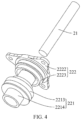
Figure 4 shows an exploded perspective view of the cable assembly shown inFigure 1 ; -
Figure 5 shows a longitudinal cross-sectional view of a cable assembly of a camera according to some embodiments of the present disclosure; -
Figure 6 shows another structural schematic diagram of a camera according to some embodiments of the present disclosure; -
Figure 7 shows a longitudinal cross-sectional view of a cable assembly of the camera shown inFigure 6 ; -
Figure 8 shows a longitudinal cross-sectional view of another cable assembly according to some embodiments of the present disclosure. - Exemplary embodiments will be described in detail herein, examples of which are illustrated in the accompanying drawings. When the following description refers to the drawings, the same numbers in different drawings refer to the same or similar elements unless otherwise indicated. The examples described in the following exemplary embodiments do not represent all examples in accordance with the disclosure. Rather, they are merely examples of apparatus and methods consistent with aspects of the invention as detailed in the appended claims.
- The terms in the disclosure is for the purpose of describing particular embodiments merely and is not intended to be limiting of the disclosure. Unless otherwise defined, technical terms or scientific terms used in the disclosure shall have the usual meaning understood by a person with ordinary skill in the art to which the disclosure relates. The "first", "second" and similar words used in the specification and claims of the disclosure do not indicate any order, quantity or importance, but are only used to distinguish different components. Likewise, "a" or "an" and similar words do not indicate a quantitative limit, but rather indicate the presence of at least one. "Multiple" or "several" means two or more than two. Unless otherwise indicated, similar terms such as "front", "rear", "lower" and/or "upper" are for convenience of description only and are not intended to limit one position or one spatial orientation. "Including" or "comprising" and other similar words mean that the elements or objects appearing before "includes" or "comprises" cover the elements or objects listed after "includes" or "comprises" and their equivalents, and do not exclude other elements or objects. "Connected to" or "connected with" and other similar words are not limited to physical or mechanical connections, but may include an electrical connection, whether direct or indirect.
- The terms in the disclosure is for the purpose of describing particular embodiments merely and is not intended to be limiting of the disclosure. As used in the disclosure and the appended claims, the singular forms "a", "the" and "this" are intended to include the plural forms as well, unless the context clearly dictates otherwise. It will also be understood that the term "and/or" as used herein refers to and includes any and all possible combinations of one or more of the associated listed items.
- The present disclosure provides a cable assembly, the cable assembly and camera of the present disclosure will be described in detail below with reference to the accompanying drawings, the following embodiments and features of the implementation may be combined with each other as long as there is no conflict.
- Referring to
Figures 1 to 5 , a first aspect of embodiments of the present disclosure provides acable assembly 100, which can be applied in an electrical device such as camera, rice cooker, refrigerator, etc., and is used for waterproof processing at core wire and connector of the electrical device. In this embodiment, a camera is used as an example to illustrate thecable assembly 100, thecable assembly 100 is configured to be assembled on amounting base 10, and includes acore wire 21 and SR (Strain relief)connector 20. Wherein themounting base 10 can be disposed on a housing of the electrical device, and thecable assembly 100 is assembled on themounting base 10 to achieve installation with the housing of the electrical device. Themounting base 10 may further be referred as a cable base, a cable fixing base, a cable fixing structure, etc. - The
SR connector 20 includes aninsertion portion 221 and a connectingportion 222, wherein theinsertion portion 221 includes a throughinsertion hole 2215, thecore wire 21 is passed through theinsertion hole 2215, and both ends of thecore wire 21 extend to outside theinsertion hole 2215, thecore wire 21 and theinsertion portion 221 are integrally provided, and the connectingportion 222 is provided outside theinsertion portion 221 for connecting with themounting base 10, the connectingportion 222 and theinsertion portion 221 are integrally provided, and a material hardness of the connectingportion 222 is greater than a material hardness of theinsertion portion 221, theinsertion portion 221 and the connectingportion 222 are integrally provided, so that theSR connector 20 is integrated with the connectingportion 222, thus it can be directly connected to themounting base 10 through the connectingportion 222, eliminating the need for the use of fasteners such as locking elements and pressing rings, reducing the number of parts, while simplifying the connection structure between thecable assembly 100 and themounting base 10, so that the connection between thecable assembly 100 and themounting base 10 is simpler and more convenient, thereby reducing material costs and installation costs. In some embodiments of the present disclosure, the material hardness of the connectingportion 222 is greater than the material hardness of theinsertion portion 221, and the connectingportion 222 has higher strength, thereby making it easier for the connectingportion 222 to be fastened to themounting base 10 and increasing the reliability and stability of thecable assembly 100. - The
core wire 21 is connected to a user's external device. Thecore wire 21 may include power supply wiring, 485 communication wiring, alarm wiring, audio wiring, optical fiber wiring, network port wiring, etc. - The connecting
portion 222 and theinsertion portion 221 together constitute aconnector body 22 of theSR connector 20, and the specific materials of the connectingportion 222 and theinsertion portion 221 are not limited. In this embodiment, the connectingportion 222 and theinsertion portion 221 are both made of plastic material. Theinsertion portion 221 includes a soft colloid, which is bonded with thesealant 224 better and can ensure better sealing performance of thesealant 224, the connectingportion 222 includes a hard colloid, which has good support and can ensure a firm fixation between thecable assembly 100 and the mountingbase 10, and the hard colloid can better compress anaxial sealing ring 225, and can better control the compression amount of theaxial sealing ring 225 to ensure sealing quality and reduce the risk of sealing failure due to aging of the soft colloid. Wherein, the soft colloid is a material with light specific gravity and relatively low surface hardness, which can be made of PVC and other materials, the hard colloid is a material with high specific gravity and relatively high surface hardness, which can be made of ABS, PBT, PA, PP and other materials. Of course, it can be selected according to different usage scenarios and service life requirements. - Referring to
Figures 3 and4 , in some embodiments of the present disclosure, theinsertion portion 221 includes afirst sleeve 2213 and asecond sleeve 2214 connected to one end of thefirst sleeve 2213, wherein thesecond sleeve 2214 protrudes outward in the transverse direction relative to thefirst sleeve 2213 to form a step surface, and the connectingportion 222 extends to the step surface and fits with the step surface, and the connectingportion 222 fits with thefirst sleeve 2213 and thesecond sleeve 2214, in this way, due to the greater hardness of the connectingportion 222, when thecore wire 21 is pulled, the connectingportion 222 can withstand the stress from an inner wall of ancable hole 11, thereby improving the bending resistance of thecable assembly 100 and reducing the risk of damage to thecable assembly 100. In this embodiment, thecore wire 21, the connectingportion 222 and theinsertion portion 221 are integrally formed by injection molding, the injection molding method may be a secondary injection molding technology or a two-color mold technology. - In some embodiments of the present disclosure, the connecting
portion 222 includes a plate-shapedsubstrate 2222 and anannular flange 2223 disposed on the plate-shapedsubstrate 2222, and theannular flange 2223 protrudes toward theinsertion portion 221, wherein theannular flange 2223 is engaged with theinsertion portion 221 in thesecond sleeve 2214, and the plate-shapedsubstrate 2222 is connected with the mountingbase 10. The shape of the plate-shapedsubstrate 2222 is not limited, and may be a triangle or other polygon, and the former is used in this embodiment. - Referring to
Figures 1 to 5 , in some embodiments of the present disclosure, theinsertion portion 221 includes agroove 2216, the connectingportion 222 includes a connectingbody 2225 and abonding wall 2226 protruding from the connectingbody 2225, thebonding wall 2226 extends into thegroove 2216 and bonds with an inner wall of thegroove 2216, thereby increasing the contact area between the connectingportion 222 and theinsertion portion 221, causing theSR connector 20 more stable. In some embodiments of the present disclosure, thegroove 2216 opens toward thefirst sleeve 2213, which can provide a certain waterproof effect. In some embodiments of the present disclosure, thegroove 2216 is an annular groove, and thebonding wall 2226 is an annular wall. By adopting a annular structure, the contact area between the connectingportion 222 and theinsertion portion 221 can be larger, and the stability of theSR connector 20 can be better. - In some embodiments of the present disclosure, the thickness of the
bonding wall 2226 is greater than or equal to 1.5 mm, which can avoid deformation or even break of the bonding wall caused by the thickness of thebonding wall 2226 being too thin, ensuring the integrated molding rate of theSR connector 20 and thecore wire 21. - In some embodiments of the present disclosure, the
insertion portion 221 includes aninsertion body 2217 and aprotrusion portion 2218 protruding from an outer side wall of theinsertion body 2217, theinsertion body 2217 is provided with aninsertion hole 2215, and theprotrusion portion 2218 is provided with agroove 2216. In some embodiments of the present disclosure, theprotrusion portion 2218 is provided on the outside of thesecond sleeve 2214, and the size of the protrusion on theprotrusion portion 2218 can be easily modified for processing according to the requirements of the depth and width of thegroove 2216 disposed on it. - In some embodiments of the present disclosure, the
protrusion portion 2218 and thegroove 2216 are located at an end of thesecond sleeve 2214 away from the step surface, which can increase the protruding distance of thebonding wall 2226 on the connectingbody 2225, thereby causing the contact area between the connectingportion 222 and theinsertion portion 221 larger, causing theSR connector 20 more stable. - In some embodiments of the present disclosure, the connecting
portion 222 includes a longitudinal connecting portion and a transverse connecting portion, the longitudinal connecting portion extends longitudinally and is connected to an outer side wall of theinsertion portion 221, the transverse connecting portion extends transversely from the longitudinal connecting portion in a direction away from thecore wire 21, the longitudinal connecting portion extends into thecable hole 11 of the mountingbase 10 and is connected to the inner wall of thecable hole 11, the transverse connecting portion extends to the outside of thecable hole 11 and covers the edge of thecable hole 11 for connecting with the surface of the mountingbase 10. In some embodiments of the present disclosure, the longitudinal connecting portion and the transverse connecting portion together form a connectingbody 2225. The longitudinal connecting portion can increase the depth of the connectingportion 222 extending into thecable hole 11 of the mountingbase 10, thereby increasing an effective fixed contact area between the connectingportion 222 and the mountingbase 10, and preventing theconnector body 22 of theSR connector 20 from being removed from the mountingbase 10, the transverse connecting portion can cover the edge of thecable hole 11 and play a certain role in waterproofing, dustproofing and sealing. - In some embodiments of the present disclosure, the hole wall of the
cable hole 11 is provided with aprotrusion 13, and theinsertion portion 221 abuts against theprotrusion 13 to prevent theinsertion portion 221 from passing through the opening on one side of thecable hole 11, which can assist in fixing thecable assembly 100 and the mountingbase 10. - In some embodiments of the present disclosure, the transverse connecting portion is provided with
multiple screw holes 2221, and thecable assembly 100 includesmultiple bolts 223 penetrating the screw holes 2221 to securely connect theSR connector 20 and the mountingbase 10, such fixing method has a simple structure and a reliable design, the screw holes 2221 on the mountingbase 10 can be directly formed along the mold ejection direction, the mold does not need to be provided with a slider mechanism, so the mold opening cost of the mountingbase 10 can be reduced. Thecable assembly 100 and the mountingbase 10 are connected through thebolts 223 to facilitate repeated disassembly and installation of thecable assembly 100. In a practical application scenario, thecable assembly 100 can be replaced separately during maintenance without replacing the mountingbase 10. - In some embodiments of the present disclosure, the
cable assembly 100 further includes asealant 224, one end of theinsertion portion 221 is formed with a dispensinggroove 2211, thecore wire 21 extends out from the dispensinggroove 2211, thesealant 224 is arranged in the dispensinggroove 2211, and is engaged with theinsertion portion 221 and thecore wire 21 in a sealing manner, wherein thesealant 224 is configured to seal a structural gap at the junction of thecore wire 21 and theinsertion portion 221 to improve the waterproof performance of the connectingportion 222 of thecore wire 21. In this embodiment, in order to ensure the sealing effect between thecore wire 21 and theinsertion portion 221, the depth of dispensing is at least 7 mm. - Referring to
Figure 2 , in some embodiments of the present disclosure, thecable assembly 100 includes aradial sealing ring 226, theradial sealing ring 226 is assembled in thecable hole 11, and theradial sealing ring 226 is clamped between theinsertion portion 221 and the inner wall of thecable hole 11, or clamped between the connectingportion 222 and the inner wall of thecable hole 11, theradial sealing ring 226 includes afirst sealing portion 2261 and asecond sealing portion 2262 distributed in an axial direction of thecable hole 11, and thefirst sealing portion 2261 is engaged with the inner wall of thecable hole 11 in a sealing manner, thesecond sealing portion 2262 is engaged with the inner wall of thecable hole 11 in a sealing manner. Under the action of the clamping force of theinsertion portion 221 and the inner wall of the cable hole 11 (or the action of the clamping force of the connectingportion 222 and the inner wall of the cable hole 11), thefirst sealing portion 2261 is compressed and deformed in the radial direction of thecable hole 11, under the action of the clamping force of theinsertion portion 221 and the inner wall of the cable hole 11 (or the action of the clamping force of the connectingportion 222 and the inner wall of the cable hole 11), thesecond sealing portion 2262 is compressed and deformed in the radial direction of thecable hole 11. Theradial sealing ring 226 is disposed between theinsertion portion 221 and the inner wall of thecable hole 11 or between the connectingportion 222 and the inner wall of thecable hole 11. On the one hand, it can solve the problem of expanding the volume of the connectingportion 222 when using theaxial sealing ring 225. On the other hand, by providing thefirst sealing portion 2261 and thesecond sealing portion 2262, theSR connector 20 can form a multi-pass sealing structure with the mountingbase 10 in thecable hole 11, thereby making up for the problem that the compression amount of theradial sealing ring 226 is uncontrollable when theinsertion portion 221 rotates into thecable hole 11. In some other embodiments of the present disclosure, theaxial sealing ring 225 and theradial sealing ring 226 may be provided simultaneously to improve the overall waterproof sealing performance of thecable assembly 100. - Referring to
Figure 5 , in some embodiments of the present disclosure, anaxial sealing ring 225 is provided on the lower surface of the transverse connecting portion to seal between the transverse connecting portion and the mountingbase 10. Theaxial sealing ring 225 compresses and deforms along the axial direction of thecable hole 11 under the action of the clamping force between the connectingportion 222 and the mountingbase 10, the axial compression amount of theaxial sealing ring 225 can be controlled by adjusting the clamping force, therefore, the sealing between the mountingbase 10 and the connectingportion 222 can be well achieved, and water can be prevented from entering between the mountingbase 10 and the connectingportion 222. Theaxial sealing ring 225 can be a V-shaped sealing ring, an O-shaped sealing ring, a rectangular sealing ring and other sealing rings, in this embodiment, theaxial sealing ring 225 is an O-shaped sealing ring with better static sealing effect, while ensuring sealing effectiveness, the O-ring diameter should be at least 2 mm. - In some embodiments of the present disclosure, the
axial sealing ring 225 is close to thecore wire 21 relative to thebolt 223, and theaxial sealing ring 225 is tightly fixed between the connectingportion 222 the mountingbase 10 through the gravity of theSR connector 20 itself and the pressure provided after being connected to thebolt 223, it can be ensured that theaxial sealing ring 225 is not easy to come out, thereby improving the sealing quality. - In some embodiments of the present disclosure, a first recessed
portion 2212 is provided on a side surface of the connectingportion 222 facing the mountingbase 10, and theaxial sealing ring 225 is assembled in the first recessedportion 2212 to prevent theaxial sealing ring 225 from being displaced. - In some other embodiments, for example, a side surface of the mounting
base 10 facing the connectingportion 222 is provided with a second recessed portion, and theaxial sealing ring 225 is assembled in the second recessed portion. As another example, a first recessedportion 2212 is provided on one side of the connectingportion 222 facing the mountingbase 10, a second recessed portion is provided on one side surface of the mountingbase 10 facing the connectingportion 222, and theaxial sealing ring 225 is assembled in a space enclosed by the first recessedportion 2212 and the second recessed portion, to ensure the position of theaxial sealing ring 225 more stable and the waterproof performance is improved. - The embodiments shown in
Figures 6 to 8 are similar to the embodiments shown inFigures 1 to 5 , compared to the embodiments shown inFigures 1 to 5 , the main differences of the embodiments shown inFigures 6 to 8 are as follows:
Thecable assembly 100 and the mountingbase 10 are fixed in different ways, one of the connectingportion 222 and the mountingbase 10 is provided with external threads, and the other is provided with internal threads, the internal threads are matched with the external threads to fix thecable assembly 100 and the mountingbase 10. Specifically, the mountingbase 10 may include a first circular sleeve protruding from the outer edge of thecable hole 11 toward the connectingportion 222, and the connectingportion 222 includes a second circular sleeve extending toward the mountingbase 10, in some embodiments of the disclosure, an outer wall of the first circular sleeve is provided with external threads, an inner wall of the second circular sleeve is provided with internal threads, and the internal threads are matched with the external threads. In other embodiments of the present disclosure, the inner wall of the first circular sleeve is provided with internal threads, the outer wall of the second circular sleeve is provided with external threads, and the internal threads are matched with the external threads. The connectingportion 222 is threadedly connected to the mountingbase 10, which can save the use of fixed components and reduce the number of parts. - Referring to
Figures 1 and6 , a second aspect of the embodiments of the present disclosure provides acamera 200, which includes a mountingbase 10 and acable assembly 100, wherein the camera includes ahousing 201, and the mountingbase 10 is provided in thehousing 201. - In the embodiment shown in
Figure 1 , thehousing 201 includes aflange 2021 provided around thecable hole 11, theflange 2021 is provided with a first connecting hole, the threaded hole is a second connecting hole, and the first connecting hole and the second connecting hole are provided for thebolts 223 to pass through, so as to fix thecable assembly 100 and thehousing 201. The purpose of providing theflange 2021 is to reduce the area of the upper end surface of theflange 2021, which is beneficial for improving the flatness of the upper end surface of theflange 2021 during the processing, making it more tightly bonded with the plate-shapedsubstrate 2222, and providing better waterproof performance. - In the embodiment shown in
Figure 6 , the connectingportion 222 is provided with external threads, and thehousing 201 includes anannular protrusion portion 2022 arranged around thecable hole 11, the inner wall of theannular protrusion portion 2022 is provided with internal threads, the internal threads are matched with the external threads to fix thecable assembly 100 and thehousing 201. The connectingportion 222 further includes ahandle 2224, thehandle 2224 is provided to cause thecable assembly 100 more labor-saving when it is rotated and installed into thecable hole 11, in some embodiments of the present disclosure, thehandle 2224 has an external hexagonal structure, which can be matched with tools such as a wrench to assist in installation and facilitate the application of installation force. - A
camera 200 is provided according to an embodiment of the present disclosure, itscable assembly 100 is configured to be assembled on the mountingbase 10, theinsertion portion 221 and the connectingportion 222 of thecable assembly 100 are integrally provided, and theinsertion portion 221 and thecore wire 21 are integrally provided, the material hardness of the connectingportion 222 is greater than that of theinsertion portion 221, and the connectingportion 222 has higher strength, thereby making it easier to maintain relative fixation with the mountingbase 10, and while eliminating the need for the use of fasteners such as locking elements and pressing rings, thus simplifying structure and reducing material costs and installation costs. - Other embodiments of the present disclosure will be readily apparent to those skilled in the art from consideration of the specification and practice of the application disclosed herein. The present disclosure is intended to cover any variations, usages, or adaptations of the disclosure that follow the general principles of the disclosure and include common sense or customary technical means in the technical field that are not disclosed in the disclosure. It is intended that the specification and embodiments be considered as exemplary only, with a true scope and spirit of the disclosure being indicated by the following claims.
- It is to be understood that the present disclosure is not limited to the precise construction described above and illustrated in the accompanying drawings, and that various modifications and changes may be made without departing from the scope thereof. The scope of the disclosure is limited only by the appended claims.
Claims (16)
- A cable assembly, for being assembled on a mounting base, the cable assembly comprising:a core wire; anda SR connector, wherein the SR connector comprises an insertion portion and a connecting portion, wherein the insertion portion comprises a through insertion hole, the core wire is passed through the insertion hole, and both ends of the core wire extend to outside the insertion hole, the core wire and the insertion portion are integrally provided, the connecting portion is provided outside the insertion portion for connecting with the mounting base, the connecting portion and the insertion portion are integrally provided, and a material hardness of the connecting portion is greater than a material hardness of the insertion portion.
- The cable assembly according to claim 1, wherein the insertion portion comprises a soft colloid, and the connecting portion comprises a hard colloid.
- The cable assembly according to claim 1, wherein the insertion portion comprises a groove, the connecting portion comprises a connecting body and a bonding wall protruding from the connecting body, the bonding wall extending into the groove, and bonding with an inner wall of the groove.
- The cable assembly according to claim 3, wherein the insertion portion comprises an insertion body and a protrusion portion protruding from an outer wall of the insertion body, and the insertion body is provided with the insertion hole, the protrusion portion is provided with the groove; preferably, the groove is an annular groove, and the bonding wall is an annular wall.
- The cable assembly according to claim 4, wherein the insertion portion comprises a first sleeve and a second sleeve connected to one end of the first sleeve, the second sleeve protrudes outward in a transverse direction relative to the first sleeve to form a step surface, the connecting portion extends to the step surface and fits with the step surface, and the connecting portion fits with the first sleeve and the second sleeve.
- The cable assembly according to claim 5, wherein the protrusion portion and the groove are provided at an end of the second sleeve away from the step surface.
- The cable assembly according to claim 5, wherein the connecting portion comprises a plate-shaped substrate and an annular flange connected to the plate-shaped substrate and protruding toward the insertion portion, the annular flange is engaged with the insertion portion in the second sleeve, and the plate-shaped substrate is connected with the mounting base.
- The cable assembly according to claim 1, wherein one of the connecting portion and the mounting base is provided with external threads, and the other is provided with internal threads, and the internal threads are matched with the external threads to fix the SR connector and the mounting base.
- The cable assembly according to claim 1, wherein the connecting portion comprises a longitudinal connecting portion and a transverse connecting portion, the longitudinal connecting portion extends longitudinally and is connected to an outer side wall of the insertion portion, and the transverse connecting portion extends transversely from the longitudinal connecting portion in a direction away from the core wire, the longitudinal connecting portion extends into a cable hole of the mounting base and is connected to an inner wall of the cable hole, the transverse connecting portion extends to outside the cable hole, covers an edge of the cable hole, and is connected with a surface of the mounting base.
- The cable assembly according to claim 9, wherein the transverse connecting portion is provided with multiple screw holes, the cable assembly comprises multiple bolts, and the bolts penetrate the screw holes and are fixed to the mounting base, to firmly connect the SR connector and the mounting base.
- The cable assembly according to claim 9, wherein a hole wall of the cable hole of the mounting base is provided with a protrusion, and the insertion portion abuts against the protrusion.
- The cable assembly according to claim 9, wherein the cable assembly comprises an axial sealing ring, and the axial sealing ring is provided on a lower surface of the transverse connecting portion and is disposed between the transverse connecting portion and the mounting base in a sealing manner.
- The cable assembly according to claim 12, wherein a first recessed portion is provided on a side surface of the connecting portion facing the mounting base, and the axial sealing ring is assembled in the first recessed portion;
a second recessed portion is provided on a side surface of the mounting seat facing the connecting portion, and the axial sealing ring is assembled in the second recessed portion. - The cable assembly according to claim 1, wherein the cable assembly further comprises a radial sealing ring, the radial sealing ring is assembled in a cable hole of the mounting base and clamped between the insertion portion and an inner wall of the cable hole, the radial sealing ring comprises a first sealing portion and a second sealing portion distributed in an axial direction of the cable hole, the first sealing portion is engaged with the inner wall of the cable hole in a sealing manner, and the second sealing portion is engaged with the inner wall of the cable hole in a sealing manner.
- The cable assembly according to claim 1, wherein the cable assembly further comprises a sealant; one end of the insertion portion is formed with a dispensing groove; the core wire extends out from the dispensing groove; and the sealant is arranged in the dispensing groove and is engaged with the insertion portion and the core wire in a sealing manner.
- A camera, comprising a mounting base and a cable assembly according to any one of claims 1 to 15, wherein the camera comprises a housing, and the mounting base is provided on the housing.
Applications Claiming Priority (2)
| Application Number | Priority Date | Filing Date | Title |
|---|---|---|---|
| CN202110779053.8A CN113540880B (en) | 2021-07-09 | 2021-07-09 | Cable assembly and camera |
| PCT/CN2022/093016 WO2023279853A1 (en) | 2021-07-09 | 2022-05-16 | Cable assembly and camera |
Publications (3)
| Publication Number | Publication Date |
|---|---|
| EP4369527A1 true EP4369527A1 (en) | 2024-05-15 |
| EP4369527A4 EP4369527A4 (en) | 2024-10-16 |
| EP4369527B1 EP4369527B1 (en) | 2025-07-30 |
Family
ID=78098268
Family Applications (1)
| Application Number | Title | Priority Date | Filing Date |
|---|---|---|---|
| EP22836609.2A Active EP4369527B1 (en) | 2021-07-09 | 2022-05-16 | Cable assembly and camera |
Country Status (3)
| Country | Link |
|---|---|
| EP (1) | EP4369527B1 (en) |
| CN (1) | CN113540880B (en) |
| WO (1) | WO2023279853A1 (en) |
Families Citing this family (2)
| Publication number | Priority date | Publication date | Assignee | Title |
|---|---|---|---|---|
| CN113540880B (en) * | 2021-07-09 | 2024-03-22 | 杭州海康威视数字技术股份有限公司 | Cable assembly and camera |
| CN114845021B (en) * | 2022-04-26 | 2023-12-01 | 杭州海康威视数字技术股份有限公司 | Image photographing device |
Family Cites Families (27)
| Publication number | Priority date | Publication date | Assignee | Title |
|---|---|---|---|---|
| US5492487A (en) * | 1993-06-07 | 1996-02-20 | Ford Motor Company | Seal retention for an electrical connector assembly |
| JPH0742018U (en) * | 1993-12-28 | 1995-07-21 | 矢崎総業株式会社 | Equipment directly attached waterproof connector |
| JP3627209B2 (en) * | 1999-04-07 | 2005-03-09 | 矢崎総業株式会社 | Shield connector structure |
| US6395985B1 (en) * | 1999-11-23 | 2002-05-28 | Sapco | Sealed electrical terminal with anti-rotation locking system |
| JP2002134191A (en) * | 2000-10-20 | 2002-05-10 | Yazaki Corp | Device connection method |
| JP4283160B2 (en) * | 2004-05-10 | 2009-06-24 | 矢崎総業株式会社 | Method for assembling case member having connector portion |
| ITGE20080004A1 (en) * | 2008-01-16 | 2009-07-17 | Ultraflex Spa | GUIDE TO DRIVE A WALL OF PIPES, CABLES OR THE LIKE. |
| EP2465901B1 (en) * | 2009-08-10 | 2016-06-01 | Yazaki Corporation | Thermoplastic elastomer resin composition and connector |
| JP5824210B2 (en) * | 2010-12-16 | 2015-11-25 | 矢崎総業株式会社 | Liquid-proof structure of wire harness |
| JP6135586B2 (en) * | 2014-04-09 | 2017-05-31 | 日立金属株式会社 | Cable fixing structure |
| WO2016038945A1 (en) * | 2014-09-11 | 2016-03-17 | オリンパス株式会社 | Insert molded article, device using said insert molded article, and method for producing insert molded article |
| JP6642089B2 (en) * | 2016-02-18 | 2020-02-05 | 住友電装株式会社 | Connector mounting structure |
| US9640965B1 (en) * | 2016-03-25 | 2017-05-02 | Protonex Technology Corporation | Cable gland assembly |
| JP2019012590A (en) * | 2017-06-29 | 2019-01-24 | Tdk株式会社 | Terminal block and electronic device |
| JP6565990B2 (en) * | 2017-08-29 | 2019-08-28 | Smk株式会社 | Electrical connector |
| CN208209118U (en) * | 2017-12-27 | 2018-12-07 | 电连技术股份有限公司 | A kind of vehicle-mounted water-proof connector |
| EP3660995B1 (en) * | 2018-11-28 | 2023-01-11 | WISKA Hoppmann GmbH | Integrally formed cable connection |
| JP7103960B2 (en) * | 2019-01-15 | 2022-07-20 | 矢崎総業株式会社 | Waterproof structure |
| DE102019106140A1 (en) * | 2019-03-11 | 2020-09-17 | Reichle + De-Massari Ag | Implementation device |
| CN210040684U (en) * | 2019-06-18 | 2020-02-07 | 苏州佑丰电子有限公司 | USB joint connector |
| TWM588385U (en) * | 2019-07-08 | 2019-12-21 | 台灣翔登股份有限公司 | Cable connector |
| CN110635303B (en) * | 2019-08-16 | 2021-02-26 | 华为技术有限公司 | a gateway device |
| JP7132195B2 (en) * | 2019-09-06 | 2022-09-06 | ショット日本株式会社 | airtight terminal |
| CN112134067A (en) * | 2020-09-30 | 2020-12-25 | Oppo广东移动通信有限公司 | Cable assembly and waterproof connecting assembly |
| CN112260025A (en) * | 2020-11-26 | 2021-01-22 | 福建飞毛腿动力科技有限公司 | Angle-adjustable connector and angle adjusting method |
| TWM612903U (en) * | 2021-03-11 | 2021-06-01 | 香港商信音科技(香港)有限公司 | Traction-enhanced type battery connector |
| CN113540880B (en) * | 2021-07-09 | 2024-03-22 | 杭州海康威视数字技术股份有限公司 | Cable assembly and camera |
-
2021
- 2021-07-09 CN CN202110779053.8A patent/CN113540880B/en active Active
-
2022
- 2022-05-16 WO PCT/CN2022/093016 patent/WO2023279853A1/en not_active Ceased
- 2022-05-16 EP EP22836609.2A patent/EP4369527B1/en active Active
Also Published As
| Publication number | Publication date |
|---|---|
| CN113540880B (en) | 2024-03-22 |
| WO2023279853A1 (en) | 2023-01-12 |
| EP4369527B1 (en) | 2025-07-30 |
| EP4369527A4 (en) | 2024-10-16 |
| CN113540880A (en) | 2021-10-22 |
Similar Documents
| Publication | Publication Date | Title |
|---|---|---|
| EP2523258B1 (en) | Electrical wire holding device | |
| US7841881B2 (en) | Waterproof cable connector | |
| US7458858B2 (en) | Electrical connector | |
| JP4951465B2 (en) | Electrical connector | |
| CA2962049A1 (en) | Cable gland assembly | |
| CN212231033U (en) | cable exit system | |
| EP4369527B1 (en) | Cable assembly and camera | |
| CN218917717U (en) | Beam-expanding watertight optical fiber connector assembly and plug | |
| CN104183987A (en) | Shielding piece for connectors and field wiring connector using same | |
| KR101413341B1 (en) | Crimp the wire gland packing with a structure | |
| JP2002184516A (en) | Waterproof connector | |
| KR101428771B1 (en) | Cable gland | |
| US20220021252A1 (en) | Stator assembly and electric motor | |
| CN111030006B (en) | A kind of underwater brittle unbreakable cable penetration waterproof device | |
| JP7617208B2 (en) | Connector rubber plug and connector | |
| WO2025185370A1 (en) | Photoelectric hybrid watertight connector | |
| US12021327B2 (en) | Signal outlet assembly with shielding wire grounded to sidewall of the housing | |
| CN111711000B (en) | Elevator cable docking structure | |
| CN223871772U (en) | Push-button RJ45 waterproof connector | |
| KR20210117814A (en) | Connecting structure of power cable and cable terminal | |
| CN103001063A (en) | Connector and limiting nut structure thereof | |
| CN116417851A (en) | Medium-high voltage connector | |
| CN113471891A (en) | Fixing piece and introducing system | |
| TWI817892B (en) | Light bar device, strain relief and its strain relief component | |
| CN111193130A (en) | High-performance radio frequency cable leakage connector clamping structure and connector |
Legal Events
| Date | Code | Title | Description |
|---|---|---|---|
| STAA | Information on the status of an ep patent application or granted ep patent |
Free format text: STATUS: THE INTERNATIONAL PUBLICATION HAS BEEN MADE |
|
| PUAI | Public reference made under article 153(3) epc to a published international application that has entered the european phase |
Free format text: ORIGINAL CODE: 0009012 |
|
| STAA | Information on the status of an ep patent application or granted ep patent |
Free format text: STATUS: REQUEST FOR EXAMINATION WAS MADE |
|
| 17P | Request for examination filed |
Effective date: 20240206 |
|
| AK | Designated contracting states |
Kind code of ref document: A1 Designated state(s): AL AT BE BG CH CY CZ DE DK EE ES FI FR GB GR HR HU IE IS IT LI LT LU LV MC MK MT NL NO PL PT RO RS SE SI SK SM TR |
|
| A4 | Supplementary search report drawn up and despatched |
Effective date: 20240917 |
|
| DAV | Request for validation of the european patent (deleted) | ||
| DAX | Request for extension of the european patent (deleted) | ||
| RIC1 | Information provided on ipc code assigned before grant |
Ipc: G03B 17/02 20210101ALI20240911BHEP Ipc: H02G 3/06 20060101ALI20240911BHEP Ipc: H01R 13/74 20060101ALI20240911BHEP Ipc: H01R 13/52 20060101AFI20240911BHEP |
|
| GRAP | Despatch of communication of intention to grant a patent |
Free format text: ORIGINAL CODE: EPIDOSNIGR1 |
|
| STAA | Information on the status of an ep patent application or granted ep patent |
Free format text: STATUS: GRANT OF PATENT IS INTENDED |
|
| RIC1 | Information provided on ipc code assigned before grant |
Ipc: G03B 17/02 20210101ALI20250211BHEP Ipc: H02G 3/06 20060101ALI20250211BHEP Ipc: H01R 13/74 20060101ALI20250211BHEP Ipc: H01R 13/52 20060101AFI20250211BHEP |
|
| INTG | Intention to grant announced |
Effective date: 20250306 |
|
| GRAS | Grant fee paid |
Free format text: ORIGINAL CODE: EPIDOSNIGR3 |
|
| GRAA | (expected) grant |
Free format text: ORIGINAL CODE: 0009210 |
|
| STAA | Information on the status of an ep patent application or granted ep patent |
Free format text: STATUS: THE PATENT HAS BEEN GRANTED |
|
| AK | Designated contracting states |
Kind code of ref document: B1 Designated state(s): AL AT BE BG CH CY CZ DE DK EE ES FI FR GB GR HR HU IE IS IT LI LT LU LV MC MK MT NL NO PL PT RO RS SE SI SK SM TR |
|
| REG | Reference to a national code |
Ref country code: GB Ref legal event code: FG4D |
|
| REG | Reference to a national code |
Ref country code: CH Ref legal event code: EP |
|
| REG | Reference to a national code |
Ref country code: DE Ref legal event code: R096 Ref document number: 602022018644 Country of ref document: DE |
|
| REG | Reference to a national code |
Ref country code: IE Ref legal event code: FG4D |
|
| REG | Reference to a national code |
Ref country code: NL Ref legal event code: MP Effective date: 20250730 |
|
| REG | Reference to a national code |
Ref country code: AT Ref legal event code: MK05 Ref document number: 1820081 Country of ref document: AT Kind code of ref document: T Effective date: 20250730 |
|
| PG25 | Lapsed in a contracting state [announced via postgrant information from national office to epo] |
Ref country code: PT Free format text: LAPSE BECAUSE OF FAILURE TO SUBMIT A TRANSLATION OF THE DESCRIPTION OR TO PAY THE FEE WITHIN THE PRESCRIBED TIME-LIMIT Effective date: 20251202 |
|
| PG25 | Lapsed in a contracting state [announced via postgrant information from national office to epo] |
Ref country code: IS Free format text: LAPSE BECAUSE OF FAILURE TO SUBMIT A TRANSLATION OF THE DESCRIPTION OR TO PAY THE FEE WITHIN THE PRESCRIBED TIME-LIMIT Effective date: 20251130 |
|
| PG25 | Lapsed in a contracting state [announced via postgrant information from national office to epo] |
Ref country code: NO Free format text: LAPSE BECAUSE OF FAILURE TO SUBMIT A TRANSLATION OF THE DESCRIPTION OR TO PAY THE FEE WITHIN THE PRESCRIBED TIME-LIMIT Effective date: 20251030 |
|
| REG | Reference to a national code |
Ref country code: LT Ref legal event code: MG9D |
|
| PG25 | Lapsed in a contracting state [announced via postgrant information from national office to epo] |
Ref country code: AT Free format text: LAPSE BECAUSE OF FAILURE TO SUBMIT A TRANSLATION OF THE DESCRIPTION OR TO PAY THE FEE WITHIN THE PRESCRIBED TIME-LIMIT Effective date: 20250730 |
|
| PG25 | Lapsed in a contracting state [announced via postgrant information from national office to epo] |
Ref country code: FI Free format text: LAPSE BECAUSE OF FAILURE TO SUBMIT A TRANSLATION OF THE DESCRIPTION OR TO PAY THE FEE WITHIN THE PRESCRIBED TIME-LIMIT Effective date: 20250730 |
|
| PG25 | Lapsed in a contracting state [announced via postgrant information from national office to epo] |
Ref country code: HR Free format text: LAPSE BECAUSE OF FAILURE TO SUBMIT A TRANSLATION OF THE DESCRIPTION OR TO PAY THE FEE WITHIN THE PRESCRIBED TIME-LIMIT Effective date: 20250730 Ref country code: NL Free format text: LAPSE BECAUSE OF FAILURE TO SUBMIT A TRANSLATION OF THE DESCRIPTION OR TO PAY THE FEE WITHIN THE PRESCRIBED TIME-LIMIT Effective date: 20250730 |
|
| PG25 | Lapsed in a contracting state [announced via postgrant information from national office to epo] |
Ref country code: GR Free format text: LAPSE BECAUSE OF FAILURE TO SUBMIT A TRANSLATION OF THE DESCRIPTION OR TO PAY THE FEE WITHIN THE PRESCRIBED TIME-LIMIT Effective date: 20251031 |
|
| PG25 | Lapsed in a contracting state [announced via postgrant information from national office to epo] |
Ref country code: SE Free format text: LAPSE BECAUSE OF FAILURE TO SUBMIT A TRANSLATION OF THE DESCRIPTION OR TO PAY THE FEE WITHIN THE PRESCRIBED TIME-LIMIT Effective date: 20250730 |
|
| PG25 | Lapsed in a contracting state [announced via postgrant information from national office to epo] |
Ref country code: LV Free format text: LAPSE BECAUSE OF FAILURE TO SUBMIT A TRANSLATION OF THE DESCRIPTION OR TO PAY THE FEE WITHIN THE PRESCRIBED TIME-LIMIT Effective date: 20250730 |
|
| PG25 | Lapsed in a contracting state [announced via postgrant information from national office to epo] |
Ref country code: PL Free format text: LAPSE BECAUSE OF FAILURE TO SUBMIT A TRANSLATION OF THE DESCRIPTION OR TO PAY THE FEE WITHIN THE PRESCRIBED TIME-LIMIT Effective date: 20250730 Ref country code: BG Free format text: LAPSE BECAUSE OF FAILURE TO SUBMIT A TRANSLATION OF THE DESCRIPTION OR TO PAY THE FEE WITHIN THE PRESCRIBED TIME-LIMIT Effective date: 20250730 |
|
| PG25 | Lapsed in a contracting state [announced via postgrant information from national office to epo] |
Ref country code: RS Free format text: LAPSE BECAUSE OF FAILURE TO SUBMIT A TRANSLATION OF THE DESCRIPTION OR TO PAY THE FEE WITHIN THE PRESCRIBED TIME-LIMIT Effective date: 20251030 |
|
| PG25 | Lapsed in a contracting state [announced via postgrant information from national office to epo] |
Ref country code: ES Free format text: LAPSE BECAUSE OF FAILURE TO SUBMIT A TRANSLATION OF THE DESCRIPTION OR TO PAY THE FEE WITHIN THE PRESCRIBED TIME-LIMIT Effective date: 20250730 |
|
| PG25 | Lapsed in a contracting state [announced via postgrant information from national office to epo] |
Ref country code: SM Free format text: LAPSE BECAUSE OF FAILURE TO SUBMIT A TRANSLATION OF THE DESCRIPTION OR TO PAY THE FEE WITHIN THE PRESCRIBED TIME-LIMIT Effective date: 20250730 |
|
| PG25 | Lapsed in a contracting state [announced via postgrant information from national office to epo] |
Ref country code: DK Free format text: LAPSE BECAUSE OF FAILURE TO SUBMIT A TRANSLATION OF THE DESCRIPTION OR TO PAY THE FEE WITHIN THE PRESCRIBED TIME-LIMIT Effective date: 20250730 |
|
| PG25 | Lapsed in a contracting state [announced via postgrant information from national office to epo] |
Ref country code: IT Free format text: LAPSE BECAUSE OF FAILURE TO SUBMIT A TRANSLATION OF THE DESCRIPTION OR TO PAY THE FEE WITHIN THE PRESCRIBED TIME-LIMIT Effective date: 20250730 |
|
| PG25 | Lapsed in a contracting state [announced via postgrant information from national office to epo] |
Ref country code: CZ Free format text: LAPSE BECAUSE OF FAILURE TO SUBMIT A TRANSLATION OF THE DESCRIPTION OR TO PAY THE FEE WITHIN THE PRESCRIBED TIME-LIMIT Effective date: 20250730 |
|
| PG25 | Lapsed in a contracting state [announced via postgrant information from national office to epo] |
Ref country code: EE Free format text: LAPSE BECAUSE OF FAILURE TO SUBMIT A TRANSLATION OF THE DESCRIPTION OR TO PAY THE FEE WITHIN THE PRESCRIBED TIME-LIMIT Effective date: 20250730 Ref country code: SK Free format text: LAPSE BECAUSE OF FAILURE TO SUBMIT A TRANSLATION OF THE DESCRIPTION OR TO PAY THE FEE WITHIN THE PRESCRIBED TIME-LIMIT Effective date: 20250730 |