EP4369486A1 - Battery module and battery pack including same - Google Patents
Battery module and battery pack including same Download PDFInfo
- Publication number
- EP4369486A1 EP4369486A1 EP22893127.5A EP22893127A EP4369486A1 EP 4369486 A1 EP4369486 A1 EP 4369486A1 EP 22893127 A EP22893127 A EP 22893127A EP 4369486 A1 EP4369486 A1 EP 4369486A1
- Authority
- EP
- European Patent Office
- Prior art keywords
- cell frame
- battery module
- battery
- adhesive layer
- module according
- Prior art date
- Legal status (The legal status is an assumption and is not a legal conclusion. Google has not performed a legal analysis and makes no representation as to the accuracy of the status listed.)
- Granted
Links
Images



Classifications
-
- H—ELECTRICITY
- H01—ELECTRIC ELEMENTS
- H01M—PROCESSES OR MEANS, e.g. BATTERIES, FOR THE DIRECT CONVERSION OF CHEMICAL ENERGY INTO ELECTRICAL ENERGY
- H01M50/00—Constructional details or processes of manufacture of the non-active parts of electrochemical cells other than fuel cells, e.g. hybrid cells
- H01M50/20—Mountings; Secondary casings or frames; Racks, modules or packs; Suspension devices; Shock absorbers; Transport or carrying devices; Holders
- H01M50/233—Mountings; Secondary casings or frames; Racks, modules or packs; Suspension devices; Shock absorbers; Transport or carrying devices; Holders characterised by physical properties of casings or racks, e.g. dimensions
-
- H—ELECTRICITY
- H01—ELECTRIC ELEMENTS
- H01M—PROCESSES OR MEANS, e.g. BATTERIES, FOR THE DIRECT CONVERSION OF CHEMICAL ENERGY INTO ELECTRICAL ENERGY
- H01M10/00—Secondary cells; Manufacture thereof
- H01M10/60—Heating or cooling; Temperature control
- H01M10/61—Types of temperature control
- H01M10/613—Cooling or keeping cold
-
- H—ELECTRICITY
- H01—ELECTRIC ELEMENTS
- H01M—PROCESSES OR MEANS, e.g. BATTERIES, FOR THE DIRECT CONVERSION OF CHEMICAL ENERGY INTO ELECTRICAL ENERGY
- H01M10/00—Secondary cells; Manufacture thereof
- H01M10/60—Heating or cooling; Temperature control
- H01M10/64—Heating or cooling; Temperature control characterised by the shape of the cells
- H01M10/643—Cylindrical cells
-
- H—ELECTRICITY
- H01—ELECTRIC ELEMENTS
- H01M—PROCESSES OR MEANS, e.g. BATTERIES, FOR THE DIRECT CONVERSION OF CHEMICAL ENERGY INTO ELECTRICAL ENERGY
- H01M10/00—Secondary cells; Manufacture thereof
- H01M10/60—Heating or cooling; Temperature control
- H01M10/65—Means for temperature control structurally associated with the cells
- H01M10/653—Means for temperature control structurally associated with the cells characterised by electrically insulating or thermally conductive materials
-
- H—ELECTRICITY
- H01—ELECTRIC ELEMENTS
- H01M—PROCESSES OR MEANS, e.g. BATTERIES, FOR THE DIRECT CONVERSION OF CHEMICAL ENERGY INTO ELECTRICAL ENERGY
- H01M10/00—Secondary cells; Manufacture thereof
- H01M10/60—Heating or cooling; Temperature control
- H01M10/65—Means for temperature control structurally associated with the cells
- H01M10/655—Solid structures for heat exchange or heat conduction
- H01M10/6554—Rods or plates
-
- H—ELECTRICITY
- H01—ELECTRIC ELEMENTS
- H01M—PROCESSES OR MEANS, e.g. BATTERIES, FOR THE DIRECT CONVERSION OF CHEMICAL ENERGY INTO ELECTRICAL ENERGY
- H01M50/00—Constructional details or processes of manufacture of the non-active parts of electrochemical cells other than fuel cells, e.g. hybrid cells
- H01M50/20—Mountings; Secondary casings or frames; Racks, modules or packs; Suspension devices; Shock absorbers; Transport or carrying devices; Holders
- H01M50/204—Racks, modules or packs for multiple batteries or multiple cells
- H01M50/207—Racks, modules or packs for multiple batteries or multiple cells characterised by their shape
- H01M50/213—Racks, modules or packs for multiple batteries or multiple cells characterised by their shape adapted for cells having curved cross-section, e.g. round or elliptic
-
- H—ELECTRICITY
- H01—ELECTRIC ELEMENTS
- H01M—PROCESSES OR MEANS, e.g. BATTERIES, FOR THE DIRECT CONVERSION OF CHEMICAL ENERGY INTO ELECTRICAL ENERGY
- H01M50/00—Constructional details or processes of manufacture of the non-active parts of electrochemical cells other than fuel cells, e.g. hybrid cells
- H01M50/20—Mountings; Secondary casings or frames; Racks, modules or packs; Suspension devices; Shock absorbers; Transport or carrying devices; Holders
- H01M50/218—Mountings; Secondary casings or frames; Racks, modules or packs; Suspension devices; Shock absorbers; Transport or carrying devices; Holders characterised by the material
- H01M50/22—Mountings; Secondary casings or frames; Racks, modules or packs; Suspension devices; Shock absorbers; Transport or carrying devices; Holders characterised by the material of the casings or racks
- H01M50/227—Organic material
-
- H—ELECTRICITY
- H01—ELECTRIC ELEMENTS
- H01M—PROCESSES OR MEANS, e.g. BATTERIES, FOR THE DIRECT CONVERSION OF CHEMICAL ENERGY INTO ELECTRICAL ENERGY
- H01M50/00—Constructional details or processes of manufacture of the non-active parts of electrochemical cells other than fuel cells, e.g. hybrid cells
- H01M50/20—Mountings; Secondary casings or frames; Racks, modules or packs; Suspension devices; Shock absorbers; Transport or carrying devices; Holders
- H01M50/218—Mountings; Secondary casings or frames; Racks, modules or packs; Suspension devices; Shock absorbers; Transport or carrying devices; Holders characterised by the material
- H01M50/22—Mountings; Secondary casings or frames; Racks, modules or packs; Suspension devices; Shock absorbers; Transport or carrying devices; Holders characterised by the material of the casings or racks
- H01M50/231—Mountings; Secondary casings or frames; Racks, modules or packs; Suspension devices; Shock absorbers; Transport or carrying devices; Holders characterised by the material of the casings or racks having a layered structure
-
- H—ELECTRICITY
- H01—ELECTRIC ELEMENTS
- H01M—PROCESSES OR MEANS, e.g. BATTERIES, FOR THE DIRECT CONVERSION OF CHEMICAL ENERGY INTO ELECTRICAL ENERGY
- H01M50/00—Constructional details or processes of manufacture of the non-active parts of electrochemical cells other than fuel cells, e.g. hybrid cells
- H01M50/20—Mountings; Secondary casings or frames; Racks, modules or packs; Suspension devices; Shock absorbers; Transport or carrying devices; Holders
- H01M50/244—Secondary casings; Racks; Suspension devices; Carrying devices; Holders characterised by their mounting method
-
- Y—GENERAL TAGGING OF NEW TECHNOLOGICAL DEVELOPMENTS; GENERAL TAGGING OF CROSS-SECTIONAL TECHNOLOGIES SPANNING OVER SEVERAL SECTIONS OF THE IPC; TECHNICAL SUBJECTS COVERED BY FORMER USPC CROSS-REFERENCE ART COLLECTIONS [XRACs] AND DIGESTS
- Y02—TECHNOLOGIES OR APPLICATIONS FOR MITIGATION OR ADAPTATION AGAINST CLIMATE CHANGE
- Y02E—REDUCTION OF GREENHOUSE GAS [GHG] EMISSIONS, RELATED TO ENERGY GENERATION, TRANSMISSION OR DISTRIBUTION
- Y02E60/00—Enabling technologies; Technologies with a potential or indirect contribution to GHG emissions mitigation
- Y02E60/10—Energy storage using batteries
Definitions
- the present disclosure relates to a battery module and a battery pack including the same, and more particularly, to a battery module whose process time is reduced, and a battery pack including the same.
- a secondary battery has attracted considerable attention as an energy source for power-driven devices, such as an electric bicycle, an electric vehicle, and a hybrid electric vehicle, as well as an energy source for mobile devices, such as a mobile phone, a digital camera and a laptop computer.
- Lithium secondary batteries which are frequently used among secondary batteries, classified based on the shape of the exterior material into a can-type secondary battery in which the electrode assembly is built into a metal can, and a pouch-type secondary battery in which the electrode assembly is built into a pouch of an aluminum laminate sheet
- the can-type secondary battery can manufacture a metal can for accommodating an electrode assembly in a cylindrical shape.
- a can-type secondary battery is provided with a housing that accommodates multiple secondary batteries, thereby realizing a battery module.
- the secondary battery is easily movable in the accommodation space inside the housing in an environment where the vehicle equipped with the battery module is subject to frequent vibrations and shocks caused by dropping, which causes problems such as damage to the secondary battery or breakage of the connection between the electrode terminal and the busbar.
- a battery module comprising: a bottom plate, a cell frame located on the bottom plate, a plurality of battery cells mounted to the cell frame, and an adhesive layer located between the bottom plate and the plurality of battery cells, wherein the cell frame has light transmittance.
- the adhesive layer may be formed of a photocurable resin.
- the cell frame may be formed with a plurality of holes for mounting the battery cells.
- the adhesive layer may be formed in the plurality of holes and contacts at least one of the bottom plate and the bottom portion of the battery cell.
- the cell frame may be formed of a resin that generates total internal reflection into the cell frame.
- the resin may have a transmittance of 90% or more.
- the battery module may further comprise a diffuse reflection member formed on a part of the surface of the cell frame.
- the diffuse reflection member may be formed on a boundary surface between the cell frame and the adhesive layer.
- a light that entered the cell frame passes through the diffuse reflection member and is emitted to the adhesive layer, so that the adhesive layer can be photo-cured.
- the adhesive layer may include a photocuring initiator.
- the bottom plate may be a cooling plate.
- the battery cell may be cylindrical.
- the bottom plate and the cell frame may be integrally formed.
- a plurality of light paths may be formed inside the cell frame.
- a battery pack comprising the above-mentioned battery module.
- a light-transmitting cell frame having a total reflection function and a photocurable resin are used as an adhesive, thereby capable of reducing a process time.
- planar it means when a target portion is viewed from the upper side
- cross-sectional it means when a target portion is viewed from the side of a cross section cut vertically.
- Fig. 1 is a diagram showing a battery module according to a comparative example.
- Fig. 2 is a diagram showing a method of forming a battery module according to the comparative example of Fig. 1 .
- a battery module 50 includes a bottom plate 20, a cell frame 30 located on the bottom plate 20, and battery cells 10 mounted in each of the plurality of holes 30h formed in the cell frame 30.
- the fixing adhesive layer 40 may be formed inside the plurality of holes 30h.
- At least one battery module 50 can be disposed inside a chamber 60, and heat can be applied to the inside of the chamber 60 via a heater 70 or the like.
- An adhesive made of a thermosetting resin is applied to the plurality of holes 30h formed in the cell frame 30 shown in Fig. 1 , and the adhesive is thermally cured to form an adhesive layer 40 shown in Fig. 1 , and the battery cell 10 can be fixed to the bottom plate 20 by the adhesive layer 40.
- Fig. 3 is a diagram showing a battery module according to one embodiment of the present disclosure.
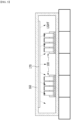
- Fig. 4 is a plan view of the cell frame shown in Fig. 3 .
- the battery module 100 includes a bottom plate 120, a cell frame 130 located on the bottom plate 120, a plurality of battery cells 110 mounted to the cell frame 130, and an adhesive layer 140 located between the bottom plate 120 and the plurality of battery cells 110.
- the adhesive layer 140 may contact at least one of the bottom plate 120 and the bottom portion of the battery cell 110.
- the bottom plate 120 may be a cooling plate for cooling the battery cell 110.
- the bottom plate 120 itself is not a cooling plate, but is used for supporting the cell frame 130 that accommodates the battery cells 110.
- a separate heat sink may be formed under the bottom plate 120.
- the cell frame 130 may have light transmittance. As the cell frame 130 has light transmittance, light generated from the light source unit can pass through the cell frame 130 in a manufacturing method of the battery module 100, which will be described below.
- the cell frame 130 may have transparent properties.
- the cell frame 130 is preferably made of a resin that generates total internal reflection into the cell frame 130. At this time, the resin may have a transmittance of 90% or more.
- the resin may be an injection molding resin.
- a plurality of holes 130h for mounting the battery cells 110 may be formed in the cell frame 130.
- the adhesive layer 140 is formed in the plurality of holes 130h so as to contact the bottom plate 120 and the cell frame 130, and the battery cell 110 may be disposed on the adhesive layer 140.
- the hole 130h formed in the cell frame 130 according to the present embodiment may be cylindrical, and the battery cell 110 is preferably a cylindrical cell that is suitable for mounting in the cylindrical hole 130h.
- the adhesive layer 140 may be made of a photocurable resin.
- the photocurable resin may be made of acrylic, silicone, epoxy, and the like, and the adhesive layer 140 preferably includes a photocuring initiator.
- the photocurable resin constituting the adhesive layer receives light, the adhesive layer 140 is formed while being cured by the photocuring initiator, and the battery cell 110 may be fixed to the cell frame 130 on the bottom plate 120 by the adhesive layer 140.
- the cell frame 130 may include a portion having holes 130h in which the plurality of battery cells 110 are mounted, and side surface frames 130s.
- the cell frame is not limited thereto, and a cell frame 130 may have a structure in which a portion having holes 130h for mounting the plurality of battery cells 110 and the side surface frames 130s are integrally formed.
- the battery module 100 shown in Fig. 3 may be a cross-sectional view taken along the line A-A' of Fig. 4 .
- Fig. 5 is a diagram showing a method of forming a battery module according to the embodiment of Fig. 3 .
- the battery module 100 disposed inside the chamber 160 shows only a part of the state where the plurality of battery cells 110 are mounted to the cell frame 130 for convenience of description and illustration.
- At least one battery module 100 may be disposed inside the chamber 160.
- a light source unit 170 is formed inside the chamber 160 to irradiate at least one battery module 100 with light.
- the light source unit 170 is located below the upper end of the chamber 160. As the light is irradiated downward, the light may reach the cell frame 130 of the battery module 100 disposed inside the chamber 160.
- the light source unit 170 may use an ultraviolet lamp or a halogen lamp.
- An adhesive formed of a photocurable resin is applied to the plurality of holes 130h formed in the cell frame 130, and the adhesive is photocured to thereby form the adhesive layer 140 shown in Fig. 3 , and the battery cell 110 may be fixed to the bottom plate 120 by the adhesive layer 140.
- a process of forming the adhesive layer 140 by photocuring will be described in detail with reference to Figs. 6 and 7 .
- Fig. 6 is a diagram showing a state in which the adhesive layer of Fig. 5 is cured.
- Fig. 7 is an enlarged view of region P of Fig. 6 .
- the battery cell 110 may be a can-type secondary battery, and the electrode assembly included in the battery cell 110 may be wrapped in a case made of metal.
- the light that has entered the cell frame 130 is totally reflected, and may be emitted to the outside of the cell frame 130 when it encounters a diffuse reflection member 190 described below. Therefore, according to the present embodiment, light entering the cell frame 130 can be emitted at the target portion.
- the cell frame 130 is made of a resin that generates total internal reflection into the cell frame 130, light entering the cell frame 130 can be prevented from escaping to the outside of the cell frame 130. In other words, after light enters the cell frame 130 having light transmittance, it may be totally reflected into the cell frame 130 so that it does not escape to the outside of the cell frame 130. Therefore, since the light entering the cell frame 130 is confined inside the cell frame 130, light efficiency can be increased.
- a resin forming the cell frame 130 may have a high refractive index compared to a medium outside the cell frame 130.
- the resin forming the cell frame 130 may be polymethyl methacrylate (PMMA) or polycarbonate (PC).
- a diffuse reflection member 190 may be formed on a part of the surface of the cell frame 130 as shown in Fig. 7 .
- the diffuse reflection pattern 190 can be formed in various patterns that cause diffuse reflection, such as intaglios and embossments.
- the diffuse reflection member 190 may be formed on a boundary surface between the cell frame 130 and the adhesive layer 140. Light that entered the cell frame 130 passes through the diffuse reflection pattern 190 and is emitted to the adhesive layer 140 so that the adhesive layer 140 can be photocured.
- the diffuse reflection member 190 has been described as a diffuse reflection pattern, but is not limited thereto, and the diffuse reflection member 190 may also include a case where particles are put therein to cause diffuse reflection.
- the plurality of light paths formed inside the cell frame 130 may be generated by bending paths of light entering from the outside of the cell frame 130 several times inside the cell frame 130.
- the cell frame 130 according to the present embodiment can be formed by injection molding, and during injection molding, the above-mentioned diffuse reflection pattern 190 may be simultaneously formed on the surface of the cell frame 130.
- the curing time of the photocurable resin for fixing the battery cell 110 to the bottom plate 120 can be significantly reduced.
- one or more battery modules according to one embodiment of the present disclosure can be packaged in a pack case to form a battery pack.
- the battery module and the battery pack including the same as set forth above can be applied to various devices.
- a device can be applied to a vehicle means such as an electric bicycle, an electric vehicle, or a hybrid vehicle, but the present disclosure is not limited thereto, and is applicable to various devices that can use a battery module and a battery pack including the same.
- battery module 10 battery cell 120: bottom plate 130: cell frame 130h: hole 140: adhesive layer 160: chamber 170: light source unit 190: diffuse reflection pattern
Landscapes
- Chemical & Material Sciences (AREA)
- Chemical Kinetics & Catalysis (AREA)
- Electrochemistry (AREA)
- General Chemical & Material Sciences (AREA)
- Engineering & Computer Science (AREA)
- Manufacturing & Machinery (AREA)
- Battery Mounting, Suspending (AREA)
- Secondary Cells (AREA)
Abstract
Description
- This application claims the benefit of
Korean Patent Application No. 10-2021-0156325 filed on November 15, 2021 Korean Patent Application No. 10-2022-0145759 filed on November 4, 2022 - The present disclosure relates to a battery module and a battery pack including the same, and more particularly, to a battery module whose process time is reduced, and a battery pack including the same.
- With the technology development and increased demand for mobile devices, demand for secondary batteries as energy sources has been rapidly increasing. A variety of researches on secondary batteries capable of meeting various needs have been carried out accordingly.
- A secondary battery has attracted considerable attention as an energy source for power-driven devices, such as an electric bicycle, an electric vehicle, and a hybrid electric vehicle, as well as an energy source for mobile devices, such as a mobile phone, a digital camera and a laptop computer.
- Lithium secondary batteries, which are frequently used among secondary batteries, classified based on the shape of the exterior material into a can-type secondary battery in which the electrode assembly is built into a metal can, and a pouch-type secondary battery in which the electrode assembly is built into a pouch of an aluminum laminate sheet
- Among them, the can-type secondary battery can manufacture a metal can for accommodating an electrode assembly in a cylindrical shape. Such a can-type secondary battery is provided with a housing that accommodates multiple secondary batteries, thereby realizing a battery module. However, when the multiple secondary batteries are accommodated in the housing inner space of the battery module without fixing means, the secondary battery is easily movable in the accommodation space inside the housing in an environment where the vehicle equipped with the battery module is subject to frequent vibrations and shocks caused by dropping, which causes problems such as damage to the secondary battery or breakage of the connection between the electrode terminal and the busbar.
- It is an object of the present disclosure to provide a battery module whose process time is reduced, and a battery pack including the same.
- However, the technical problem to be solved by embodiments of the present disclosure is not limited to the above-described problems, and can be variously expanded within the scope of the technical idea included in the present disclosure.
- According to one aspect of the present disclosure, there is provided a battery module comprising: a bottom plate, a cell frame located on the bottom plate, a plurality of battery cells mounted to the cell frame, and an adhesive layer located between the bottom plate and the plurality of battery cells, wherein the cell frame has light transmittance.
- The adhesive layer may be formed of a photocurable resin.
- The cell frame may be formed with a plurality of holes for mounting the battery cells.
- The adhesive layer may be formed in the plurality of holes and contacts at least one of the bottom plate and the bottom portion of the battery cell.
- The cell frame may be formed of a resin that generates total internal reflection into the cell frame.
- The resin may have a transmittance of 90% or more.
- The battery module may further comprise a diffuse reflection member formed on a part of the surface of the cell frame.
- The diffuse reflection member may be formed on a boundary surface between the cell frame and the adhesive layer.
- A light that entered the cell frame passes through the diffuse reflection member and is emitted to the adhesive layer, so that the adhesive layer can be photo-cured.
- The adhesive layer may include a photocuring initiator.
- The bottom plate may be a cooling plate.
- The battery cell may be cylindrical.
- The bottom plate and the cell frame may be integrally formed.
- A plurality of light paths may be formed inside the cell frame.
- According to another aspect of the present disclosure, there is provided a battery pack comprising the above-mentioned battery module.
- According to embodiments, a light-transmitting cell frame having a total reflection function and a photocurable resin are used as an adhesive, thereby capable of reducing a process time.
- The effects of the present disclosure are not limited to the effects mentioned above and additional other effects not described above will be clearly understood from the description of the appended claims by those skilled in the art.
-
-
Fig. 1 is a diagram showing a battery module according to a comparative example; -
Fig. 2 is a diagram showing a method of forming a battery module according to the comparative example ofFig. 1 ; -
Fig. 3 is a diagram showing a battery module according to one embodiment of the present disclosure; -
Fig. 4 is a plan view of the cell frame shown inFig. 3 ; -
Fig. 5 is a diagram showing a method of forming a battery module according to the embodiment ofFig. 3 ; -
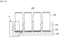
Fig. 6 is a diagram showing a state in which the adhesive layer ofFig. 5 is cured; and -
Fig. 7 is an enlarged view of region P ofFig. 6 . - Hereinafter, various embodiments of the present disclosure will be described in detail with reference to the accompanying drawings so that those skilled in the art can easily carry out them. The present disclosure may be modified in various different ways, and is not limited to the embodiments set forth herein.
- Portions that are irrelevant to the description will be omitted to clearly describe the present disclosure, and like reference numerals designate like elements throughout the description.
- Further, in the drawings, the size and thickness of each element are arbitrarily illustrated for convenience of description, and the present disclosure is not necessarily limited to those illustrated in the drawings. In the drawings, the thickness of layers, regions, etc. are exaggerated for clarity. In the drawings, for convenience of description, the thicknesses of a part and an area are exaggerated.
- Further, it will be understood that when an element such as a layer, film, region, or plate is referred to as being "on" or "above" another element, it can be directly on the other element or intervening elements may also be present. In contrast, when an element is referred to as being "directly on" another element, it means that other intervening elements are not present. Further, a certain part being located "above" or "on" a reference portion means the certain part being located above or below the reference portion and does not particularly mean the certain part "above" or "on" toward an opposite direction of gravity.
- Further, throughout the description, when a portion is referred to as "including" or "comprising" a certain component, it means that the portion can further include other components, without excluding the other components, unless otherwise stated.
- Further, throughout the description, when it is referred to as "planar", it means when a target portion is viewed from the upper side, and when it is referred to as "cross-sectional", it means when a target portion is viewed from the side of a cross section cut vertically.
-
Fig. 1 is a diagram showing a battery module according to a comparative example.Fig. 2 is a diagram showing a method of forming a battery module according to the comparative example ofFig. 1 . - Referring to
Fig. 1 , abattery module 50 according to a comparative example includes abottom plate 20, acell frame 30 located on thebottom plate 20, andbattery cells 10 mounted in each of the plurality ofholes 30h formed in thecell frame 30. At this time, in order to fix thebattery cell 10 to thebottom plate 20, the fixingadhesive layer 40 may be formed inside the plurality ofholes 30h. - Referring to
Fig. 2 , at least onebattery module 50 can be disposed inside achamber 60, and heat can be applied to the inside of thechamber 60 via aheater 70 or the like. An adhesive made of a thermosetting resin is applied to the plurality ofholes 30h formed in thecell frame 30 shown inFig. 1 , and the adhesive is thermally cured to form anadhesive layer 40 shown inFig. 1 , and thebattery cell 10 can be fixed to thebottom plate 20 by theadhesive layer 40. However, it may take a long process time until thermal curing is performed within thechamber 60 to form anadhesive layer 40. -
Fig. 3 is a diagram showing a battery module according to one embodiment of the present disclosure.Fig. 4 is a plan view of the cell frame shown inFig. 3 . - Referring to
Fig. 3 , thebattery module 100 according to the present embodiment includes abottom plate 120, acell frame 130 located on thebottom plate 120, a plurality ofbattery cells 110 mounted to thecell frame 130, and anadhesive layer 140 located between thebottom plate 120 and the plurality ofbattery cells 110. At this time, theadhesive layer 140 may contact at least one of thebottom plate 120 and the bottom portion of thebattery cell 110. - The
bottom plate 120 according to the present embodiment may be a cooling plate for cooling thebattery cell 110. However, thebottom plate 120 itself is not a cooling plate, but is used for supporting thecell frame 130 that accommodates thebattery cells 110. A separate heat sink may be formed under thebottom plate 120. - The
cell frame 130 according to the present embodiment may have light transmittance. As thecell frame 130 has light transmittance, light generated from the light source unit can pass through thecell frame 130 in a manufacturing method of thebattery module 100, which will be described below. Thecell frame 130 may have transparent properties. Specifically, thecell frame 130 is preferably made of a resin that generates total internal reflection into thecell frame 130. At this time, the resin may have a transmittance of 90% or more. The resin may be an injection molding resin. - Referring to
Figs. 3 and 4 , a plurality ofholes 130h for mounting thebattery cells 110 may be formed in thecell frame 130. Theadhesive layer 140 is formed in the plurality ofholes 130h so as to contact thebottom plate 120 and thecell frame 130, and thebattery cell 110 may be disposed on theadhesive layer 140. - The
hole 130h formed in thecell frame 130 according to the present embodiment may be cylindrical, and thebattery cell 110 is preferably a cylindrical cell that is suitable for mounting in thecylindrical hole 130h. - The
adhesive layer 140 according to the present embodiment may be made of a photocurable resin. At this time, the photocurable resin may be made of acrylic, silicone, epoxy, and the like, and theadhesive layer 140 preferably includes a photocuring initiator. When the photocurable resin constituting the adhesive layer receives light, theadhesive layer 140 is formed while being cured by the photocuring initiator, and thebattery cell 110 may be fixed to thecell frame 130 on thebottom plate 120 by theadhesive layer 140. - As shown in
Fig. 4 , thecell frame 130 may include aportion having holes 130h in which the plurality ofbattery cells 110 are mounted, and side surface frames 130s. However, the cell frame is not limited thereto, and acell frame 130 may have a structure in which aportion having holes 130h for mounting the plurality ofbattery cells 110 and the side surface frames 130s are integrally formed. Thebattery module 100 shown inFig. 3 may be a cross-sectional view taken along the line A-A' ofFig. 4 . -
Fig. 5 is a diagram showing a method of forming a battery module according to the embodiment ofFig. 3 . InFig. 5 , thebattery module 100 disposed inside thechamber 160 shows only a part of the state where the plurality ofbattery cells 110 are mounted to thecell frame 130 for convenience of description and illustration. - Referring to
Figs. 3 and5 , at least onebattery module 100 may be disposed inside thechamber 160. Alight source unit 170 is formed inside thechamber 160 to irradiate at least onebattery module 100 with light. Thelight source unit 170 is located below the upper end of thechamber 160. As the light is irradiated downward, the light may reach thecell frame 130 of thebattery module 100 disposed inside thechamber 160. - The
light source unit 170 according to the present embodiment may use an ultraviolet lamp or a halogen lamp. - An adhesive formed of a photocurable resin is applied to the plurality of
holes 130h formed in thecell frame 130, and the adhesive is photocured to thereby form theadhesive layer 140 shown inFig. 3 , and thebattery cell 110 may be fixed to thebottom plate 120 by theadhesive layer 140. A process of forming theadhesive layer 140 by photocuring will be described in detail with reference toFigs. 6 and7 . -
Fig. 6 is a diagram showing a state in which the adhesive layer ofFig. 5 is cured.Fig. 7 is an enlarged view of region P ofFig. 6 . - Referring to
Figs. 5 to 7 , when light generated from thelight source unit 170 disposed inside thechamber 160 is irradiated toward thebattery module 100, light enters into thecell frame 130 having light transmittance. Light entering thecell frame 130 may have several paths. - The
battery cell 110 may be a can-type secondary battery, and the electrode assembly included in thebattery cell 110 may be wrapped in a case made of metal. The light that has entered thecell frame 130 is totally reflected, and may be emitted to the outside of thecell frame 130 when it encounters a diffusereflection member 190 described below. Therefore, according to the present embodiment, light entering thecell frame 130 can be emitted at the target portion. - At this time, according to the present embodiment, as the
cell frame 130 is made of a resin that generates total internal reflection into thecell frame 130, light entering thecell frame 130 can be prevented from escaping to the outside of thecell frame 130. In other words, after light enters thecell frame 130 having light transmittance, it may be totally reflected into thecell frame 130 so that it does not escape to the outside of thecell frame 130. Therefore, since the light entering thecell frame 130 is confined inside thecell frame 130, light efficiency can be increased. A resin forming thecell frame 130 may have a high refractive index compared to a medium outside thecell frame 130. In one example, the resin forming thecell frame 130 may be polymethyl methacrylate (PMMA) or polycarbonate (PC). - In this manner, in order for a plurality of light paths to be formed inside the
cell frame 130 and for such light to form theadhesive layer 140, the light must be able to reach an adhesive made of a thermosetting resin applied between thebattery cell 110 and the bottom plate. For this purpose, according to the present embodiment, a diffusereflection member 190 may be formed on a part of the surface of thecell frame 130 as shown inFig. 7 . As an example of the diffusereflection member 190, the diffusereflection pattern 190 can be formed in various patterns that cause diffuse reflection, such as intaglios and embossments. The diffusereflection member 190 may be formed on a boundary surface between thecell frame 130 and theadhesive layer 140. Light that entered thecell frame 130 passes through the diffusereflection pattern 190 and is emitted to theadhesive layer 140 so that theadhesive layer 140 can be photocured. - In the present embodiment, the diffuse
reflection member 190 has been described as a diffuse reflection pattern, but is not limited thereto, and the diffusereflection member 190 may also include a case where particles are put therein to cause diffuse reflection. - The plurality of light paths formed inside the
cell frame 130 may be generated by bending paths of light entering from the outside of thecell frame 130 several times inside thecell frame 130. - The
cell frame 130 according to the present embodiment can be formed by injection molding, and during injection molding, the above-mentioned diffusereflection pattern 190 may be simultaneously formed on the surface of thecell frame 130. - Due to the diffuse
reflection pattern 190 formed on the surface of thecell frame 130 according to the present embodiment, the curing time of the photocurable resin for fixing thebattery cell 110 to thebottom plate 120 can be significantly reduced. - Meanwhile, one or more battery modules according to one embodiment of the present disclosure can be packaged in a pack case to form a battery pack. The battery module and the battery pack including the same as set forth above can be applied to various devices. Such a device can be applied to a vehicle means such as an electric bicycle, an electric vehicle, or a hybrid vehicle, but the present disclosure is not limited thereto, and is applicable to various devices that can use a battery module and a battery pack including the same.
- Although preferred embodiments of the present disclosure have been described in detail above, the scope of the present disclosure is not limited thereto, and various modifications and improvements can be made by those skilled in the art using the basic concepts of the present disclosure as defined in the appended claims, which also falls within the scope of the present disclosure.
-
100: battery module 10: battery cell 120: bottom plate 130: cell frame 130h: hole 140: adhesive layer 160: chamber 170: light source unit 190: diffuse reflection pattern
Claims (15)
- A battery module comprising:a bottom plate,a cell frame located on the bottom plate,a plurality of battery cells mounted to the cell frame, andan adhesive layer located between the bottom plate and the plurality of battery cells,wherein the cell frame has light transmittance.
- The battery module according to claim 1, wherein:
the adhesive layer is formed of a photocurable resin. - The battery module according to claim 1, wherein:
the cell frame is formed with a plurality of holes for mounting the battery cells. - The battery module according to claim 3, wherein:
the adhesive layer is formed in the plurality of holes and contacts at least one of the bottom plate and the bottom portion of the battery cell. - The battery module according to claim 1, wherein:
the cell frame is formed of a resin that generates total internal reflection into the cell frame. - The battery module according to claim 5, wherein:
the resin has a transmittance of 90% or more. - The battery module according to claim 1, further comprising:
a diffuse reflection member formed on a part of the surface of the cell frame. - The battery module according to claim 7, wherein:
the diffuse reflection member is formed on a boundary surface between the cell frame and the adhesive layer. - The battery module according to claim 8, wherein:
a light that entered the cell frame passes through the diffuse reflection member and is emitted to the adhesive layer, so that the adhesive layer is photo-cured. - The battery module according to claim 1, wherein:
the adhesive layer includes a photocuring initiator. - The battery module according to claim 1, wherein:
the bottom plate is a cooling plate. - The battery module according to claim 1, wherein:
the battery cell is cylindrical. - The battery module according to claim 1, wherein:
the bottom plate and the cell frame are integrally formed. - The battery module according to claim 1, wherein:
a plurality of light paths are formed inside the cell frame. - A battery pack comprising the battery module as set forth in claim 1.
Applications Claiming Priority (3)
| Application Number | Priority Date | Filing Date | Title |
|---|---|---|---|
| KR20210156325 | 2021-11-15 | ||
| KR1020220145759A KR20230071065A (en) | 2021-11-15 | 2022-11-04 | Battery module and battery pack including the same |
| PCT/KR2022/017332 WO2023085706A1 (en) | 2021-11-15 | 2022-11-07 | Battery module and battery pack including same |
Publications (3)
| Publication Number | Publication Date |
|---|---|
| EP4369486A1 true EP4369486A1 (en) | 2024-05-15 |
| EP4369486A4 EP4369486A4 (en) | 2025-02-12 |
| EP4369486B1 EP4369486B1 (en) | 2026-05-06 |
Family
ID=86336045
Family Applications (1)
| Application Number | Title | Priority Date | Filing Date |
|---|---|---|---|
| EP22893127.5A Active EP4369486B1 (en) | 2021-11-15 | 2022-11-07 | Battery module and battery pack including the same |
Country Status (4)
| Country | Link |
|---|---|
| US (1) | US20240363940A1 (en) |
| EP (1) | EP4369486B1 (en) |
| JP (1) | JP7744084B2 (en) |
| WO (1) | WO2023085706A1 (en) |
Family Cites Families (15)
| Publication number | Priority date | Publication date | Assignee | Title |
|---|---|---|---|---|
| FR2924857B1 (en) * | 2007-12-06 | 2014-06-06 | Valeo Equip Electr Moteur | ELECTRICAL SUPPLY DEVICE COMPRISING A RECEPTION UNIT FOR ULTRA CAPACITY STORAGE UNITS |
| US20120261066A1 (en) * | 2011-04-15 | 2012-10-18 | Covidien Ag | Sealed Device and Method of Sealing |
| US9403296B2 (en) * | 2012-04-12 | 2016-08-02 | Telsa Motors, Inc. | Embedded optics in modular assemblies |
| KR101941117B1 (en) * | 2015-02-27 | 2019-01-23 | 주식회사 엘지화학 | Battery module |
| CN206134883U (en) * | 2016-11-02 | 2017-04-26 | 上海工程技术大学 | A thermal management device for battery modules based on thermoelectric effect |
| JP6583219B2 (en) * | 2016-11-15 | 2019-10-02 | トヨタ自動車株式会社 | Battery module |
| US10601090B2 (en) * | 2017-04-28 | 2020-03-24 | Nio Usa, Inc. | Using a spacer to block path of thermally conductive structural adhesive in lithium ion cells |
| CN106935758A (en) * | 2017-05-16 | 2017-07-07 | 惠州亿纬锂能股份有限公司 | High-performance heat management electrokinetic cell module and battery pack |
| KR102090255B1 (en) * | 2018-02-02 | 2020-03-17 | 주식회사 엘지화학 | Method for Manufacturing Battery Module and Battery Module |
| US20200185798A1 (en) * | 2018-12-05 | 2020-06-11 | Nio Usa, Inc. | Method and system for joining cells to a battery coldplate |
| KR20210156325A (en) | 2019-05-15 | 2021-12-24 | 코닝 인코포레이티드 | System and method for edge strength testing with real-time stress visualization in ultra-thin glass panels |
| CN210379158U (en) * | 2019-08-08 | 2020-04-21 | 欣旺达电动汽车电池有限公司 | Battery module |
| EP3800687A4 (en) * | 2019-08-08 | 2022-04-13 | Sunwoda Electric Vehicle Battery Co., Ltd. | BATTERY MODULE |
| EP4064431A4 (en) * | 2020-06-16 | 2023-11-29 | LG Energy Solution, Ltd. | BATTERY, ELECTRONIC DEVICE INCLUDING SAME, AND VEHICLE |
| KR102725291B1 (en) | 2021-04-22 | 2024-11-01 | (주) 래트론 | Flexible Heater and the Manufacturing Method thereof |
-
2022
- 2022-11-07 WO PCT/KR2022/017332 patent/WO2023085706A1/en not_active Ceased
- 2022-11-07 JP JP2024502535A patent/JP7744084B2/en active Active
- 2022-11-07 US US18/682,018 patent/US20240363940A1/en active Pending
- 2022-11-07 EP EP22893127.5A patent/EP4369486B1/en active Active
Also Published As
| Publication number | Publication date |
|---|---|
| EP4369486B1 (en) | 2026-05-06 |
| JP2024526358A (en) | 2024-07-17 |
| US20240363940A1 (en) | 2024-10-31 |
| EP4369486A4 (en) | 2025-02-12 |
| JP7744084B2 (en) | 2025-09-25 |
| WO2023085706A1 (en) | 2023-05-19 |
Similar Documents
| Publication | Publication Date | Title |
|---|---|---|
| US11870046B2 (en) | Battery pack | |
| US10665910B2 (en) | Battery pack using direct cooling method on edge surface of battery | |
| CN113711433B (en) | Battery module and battery pack including the battery module | |
| CN113795972B (en) | Battery module and battery pack including the battery module | |
| KR102807505B1 (en) | Battery module, battery pack including the same and method of manufacturing battery pack | |
| US12155050B2 (en) | Battery module and battery pack including the same | |
| CN115428244B (en) | Battery module and battery pack including the same | |
| JP2022517685A (en) | Battery module, its manufacturing method and battery pack | |
| EP3823085B1 (en) | Stacked battery pack | |
| EP4020698A1 (en) | Battery module, battery pack including same, and method of manufacturing battery module | |
| EP4170798A1 (en) | Battery module and battery pack comprising same | |
| EP4040575A1 (en) | Battery module and battery pack including same | |
| EP4369486A1 (en) | Battery module and battery pack including same | |
| CN113439361B (en) | Battery module and battery pack including the battery module | |
| KR20230071065A (en) | Battery module and battery pack including the same | |
| EP4020687A1 (en) | Battery module, battery pack including same, and method for transporting battery module | |
| KR102928037B1 (en) | Battery module including a heat sink with a guide hole | |
| CN117916934A (en) | Battery module and battery pack including the battery module | |
| JP2018056092A (en) | Battery module | |
| CN110495017A (en) | Connection board and battery module including the same | |
| JP3929032B2 (en) | Battery pack manufacturing method | |
| EP4645531A1 (en) | Battery module and battery pack including same | |
| CN103534636A (en) | Liquid crystal display device | |
| EP4648181A1 (en) | Battery module and battery pack including same | |
| CN120883431A (en) | Electrical equipment with labels |
Legal Events
| Date | Code | Title | Description |
|---|---|---|---|
| STAA | Information on the status of an ep patent application or granted ep patent |
Free format text: STATUS: THE INTERNATIONAL PUBLICATION HAS BEEN MADE |
|
| PUAI | Public reference made under article 153(3) epc to a published international application that has entered the european phase |
Free format text: ORIGINAL CODE: 0009012 |
|
| STAA | Information on the status of an ep patent application or granted ep patent |
Free format text: STATUS: REQUEST FOR EXAMINATION WAS MADE |
|
| 17P | Request for examination filed |
Effective date: 20240209 |
|
| AK | Designated contracting states |
Kind code of ref document: A1 Designated state(s): AL AT BE BG CH CY CZ DE DK EE ES FI FR GB GR HR HU IE IS IT LI LT LU LV MC ME MK MT NL NO PL PT RO RS SE SI SK SM TR |
|
| A4 | Supplementary search report drawn up and despatched |
Effective date: 20250113 |
|
| RIC1 | Information provided on ipc code assigned before grant |
Ipc: H01M 10/613 20140101ALI20250107BHEP Ipc: H01M 10/643 20140101ALI20250107BHEP Ipc: H01M 10/6554 20140101ALI20250107BHEP Ipc: H01M 50/213 20210101ALI20250107BHEP Ipc: H01M 50/227 20210101ALI20250107BHEP Ipc: H01M 10/653 20140101ALI20250107BHEP Ipc: H01M 50/233 20210101AFI20250107BHEP |
|
| DAV | Request for validation of the european patent (deleted) | ||
| DAX | Request for extension of the european patent (deleted) | ||
| STAA | Information on the status of an ep patent application or granted ep patent |
Free format text: STATUS: EXAMINATION IS IN PROGRESS |
|
| 17Q | First examination report despatched |
Effective date: 20250707 |
|
| GRAP | Despatch of communication of intention to grant a patent |
Free format text: ORIGINAL CODE: EPIDOSNIGR1 |
|
| STAA | Information on the status of an ep patent application or granted ep patent |
Free format text: STATUS: GRANT OF PATENT IS INTENDED |
|
| INTG | Intention to grant announced |
Effective date: 20251215 |
|
| P01 | Opt-out of the competence of the unified patent court (upc) registered |
Free format text: CASE NUMBER: UPC_APP_0000284_4369486/2026 Effective date: 20260106 |
|
| GRAS | Grant fee paid |
Free format text: ORIGINAL CODE: EPIDOSNIGR3 |
|
| GRAA | (expected) grant |
Free format text: ORIGINAL CODE: 0009210 |
|
| STAA | Information on the status of an ep patent application or granted ep patent |
Free format text: STATUS: THE PATENT HAS BEEN GRANTED |