EP4369483A2 - Electrochemical apparatus and electric apparatus - Google Patents
Electrochemical apparatus and electric apparatus Download PDFInfo
- Publication number
- EP4369483A2 EP4369483A2 EP23209461.5A EP23209461A EP4369483A2 EP 4369483 A2 EP4369483 A2 EP 4369483A2 EP 23209461 A EP23209461 A EP 23209461A EP 4369483 A2 EP4369483 A2 EP 4369483A2
- Authority
- EP
- European Patent Office
- Prior art keywords
- housing
- insulation layer
- conductor
- electrochemical apparatus
- insulator
- Prior art date
- Legal status (The legal status is an assumption and is not a legal conclusion. Google has not performed a legal analysis and makes no representation as to the accuracy of the status listed.)
- Pending
Links
- 238000009413 insulation Methods 0.000 claims abstract description 126
- 239000004020 conductor Substances 0.000 claims abstract description 99
- 239000012212 insulator Substances 0.000 claims abstract description 62
- 238000002844 melting Methods 0.000 claims description 37
- 230000008018 melting Effects 0.000 claims description 37
- -1 polyethylene Polymers 0.000 claims description 15
- 239000004743 Polypropylene Substances 0.000 claims description 8
- 229920001155 polypropylene Polymers 0.000 claims description 8
- 239000004698 Polyethylene Substances 0.000 claims description 7
- 229920000573 polyethylene Polymers 0.000 claims description 7
- 229920005989 resin Polymers 0.000 claims description 7
- 239000011347 resin Substances 0.000 claims description 7
- NIXOWILDQLNWCW-UHFFFAOYSA-N acrylic acid group Chemical group C(C=C)(=O)O NIXOWILDQLNWCW-UHFFFAOYSA-N 0.000 claims description 6
- PIICEJLVQHRZGT-UHFFFAOYSA-N Ethylenediamine Chemical compound NCCN PIICEJLVQHRZGT-UHFFFAOYSA-N 0.000 claims description 5
- 229920005672 polyolefin resin Polymers 0.000 claims description 5
- 229920000098 polyolefin Polymers 0.000 claims description 4
- 229920000915 polyvinyl chloride Polymers 0.000 claims description 3
- 239000004800 polyvinyl chloride Substances 0.000 claims description 3
- 229920001577 copolymer Polymers 0.000 claims description 2
- 229920001973 fluoroelastomer Polymers 0.000 claims description 2
- 238000004880 explosion Methods 0.000 description 12
- 238000007373 indentation Methods 0.000 description 11
- 238000004806 packaging method and process Methods 0.000 description 10
- 239000000306 component Substances 0.000 description 8
- 238000010586 diagram Methods 0.000 description 8
- 239000002131 composite material Substances 0.000 description 6
- 238000000034 method Methods 0.000 description 6
- 239000003792 electrolyte Substances 0.000 description 5
- 239000000463 material Substances 0.000 description 5
- 239000000155 melt Substances 0.000 description 5
- 229910052751 metal Inorganic materials 0.000 description 5
- 239000002184 metal Substances 0.000 description 5
- 238000007789 sealing Methods 0.000 description 5
- 239000003292 glue Substances 0.000 description 4
- 238000007731 hot pressing Methods 0.000 description 4
- 238000004519 manufacturing process Methods 0.000 description 4
- 230000002265 prevention Effects 0.000 description 4
- 239000007787 solid Substances 0.000 description 4
- 238000005516 engineering process Methods 0.000 description 3
- 239000007788 liquid Substances 0.000 description 3
- 229910000838 Al alloy Inorganic materials 0.000 description 2
- 229910000851 Alloy steel Inorganic materials 0.000 description 2
- 229910000881 Cu alloy Inorganic materials 0.000 description 2
- 229910000640 Fe alloy Inorganic materials 0.000 description 2
- 229910000990 Ni alloy Inorganic materials 0.000 description 2
- 238000010276 construction Methods 0.000 description 2
- 238000005260 corrosion Methods 0.000 description 2
- 230000007797 corrosion Effects 0.000 description 2
- FPYJFEHAWHCUMM-UHFFFAOYSA-N maleic anhydride Chemical compound O=C1OC(=O)C=C1 FPYJFEHAWHCUMM-UHFFFAOYSA-N 0.000 description 2
- 230000000116 mitigating effect Effects 0.000 description 2
- 239000004033 plastic Substances 0.000 description 2
- 229920003023 plastic Polymers 0.000 description 2
- 239000000565 sealant Substances 0.000 description 2
- 239000002699 waste material Substances 0.000 description 2
- 229910001339 C alloy Inorganic materials 0.000 description 1
- HBBGRARXTFLTSG-UHFFFAOYSA-N Lithium ion Chemical compound [Li+] HBBGRARXTFLTSG-UHFFFAOYSA-N 0.000 description 1
- 241000238367 Mya arenaria Species 0.000 description 1
- 239000004952 Polyamide Substances 0.000 description 1
- 239000004642 Polyimide Substances 0.000 description 1
- 239000004793 Polystyrene Substances 0.000 description 1
- XECAHXYUAAWDEL-UHFFFAOYSA-N acrylonitrile butadiene styrene Chemical compound C=CC=C.C=CC#N.C=CC1=CC=CC=C1 XECAHXYUAAWDEL-UHFFFAOYSA-N 0.000 description 1
- 229920000122 acrylonitrile butadiene styrene Polymers 0.000 description 1
- 239000004676 acrylonitrile butadiene styrene Substances 0.000 description 1
- 229910052782 aluminium Inorganic materials 0.000 description 1
- XAGFODPZIPBFFR-UHFFFAOYSA-N aluminium Chemical compound [Al] XAGFODPZIPBFFR-UHFFFAOYSA-N 0.000 description 1
- 230000009286 beneficial effect Effects 0.000 description 1
- 239000003990 capacitor Substances 0.000 description 1
- 229920001940 conductive polymer Polymers 0.000 description 1
- 239000008358 core component Substances 0.000 description 1
- 238000005336 cracking Methods 0.000 description 1
- 238000007599 discharging Methods 0.000 description 1
- 238000005530 etching Methods 0.000 description 1
- 230000017525 heat dissipation Effects 0.000 description 1
- 230000001788 irregular Effects 0.000 description 1
- 239000004973 liquid crystal related substance Substances 0.000 description 1
- 229910001416 lithium ion Inorganic materials 0.000 description 1
- 239000007769 metal material Substances 0.000 description 1
- QMQXDJATSGGYDR-UHFFFAOYSA-N methylidyneiron Chemical compound [C].[Fe] QMQXDJATSGGYDR-UHFFFAOYSA-N 0.000 description 1
- 229920002647 polyamide Polymers 0.000 description 1
- 229920000515 polycarbonate Polymers 0.000 description 1
- 239000004417 polycarbonate Substances 0.000 description 1
- 229920000728 polyester Polymers 0.000 description 1
- 229920001721 polyimide Polymers 0.000 description 1
- 239000002861 polymer material Substances 0.000 description 1
- 229920002223 polystyrene Polymers 0.000 description 1
- 238000002360 preparation method Methods 0.000 description 1
- 229910001220 stainless steel Inorganic materials 0.000 description 1
- 239000010935 stainless steel Substances 0.000 description 1
- 230000009466 transformation Effects 0.000 description 1
- 238000000844 transformation Methods 0.000 description 1
- 238000003466 welding Methods 0.000 description 1
- 238000004804 winding Methods 0.000 description 1
Images



Classifications
-
- H—ELECTRICITY
- H01—ELECTRIC ELEMENTS
- H01M—PROCESSES OR MEANS, e.g. BATTERIES, FOR THE DIRECT CONVERSION OF CHEMICAL ENERGY INTO ELECTRICAL ENERGY
- H01M50/00—Constructional details or processes of manufacture of the non-active parts of electrochemical cells other than fuel cells, e.g. hybrid cells
- H01M50/30—Arrangements for facilitating escape of gases
- H01M50/342—Non-re-sealable arrangements
- H01M50/3425—Non-re-sealable arrangements in the form of rupturable membranes or weakened parts, e.g. pierced with the aid of a sharp member
-
- H—ELECTRICITY
- H01—ELECTRIC ELEMENTS
- H01M—PROCESSES OR MEANS, e.g. BATTERIES, FOR THE DIRECT CONVERSION OF CHEMICAL ENERGY INTO ELECTRICAL ENERGY
- H01M50/00—Constructional details or processes of manufacture of the non-active parts of electrochemical cells other than fuel cells, e.g. hybrid cells
- H01M50/10—Primary casings; Jackets or wrappings
- H01M50/102—Primary casings; Jackets or wrappings characterised by their shape or physical structure
- H01M50/107—Primary casings; Jackets or wrappings characterised by their shape or physical structure having curved cross-section, e.g. round or elliptic
-
- H—ELECTRICITY
- H01—ELECTRIC ELEMENTS
- H01M—PROCESSES OR MEANS, e.g. BATTERIES, FOR THE DIRECT CONVERSION OF CHEMICAL ENERGY INTO ELECTRICAL ENERGY
- H01M50/00—Constructional details or processes of manufacture of the non-active parts of electrochemical cells other than fuel cells, e.g. hybrid cells
- H01M50/10—Primary casings; Jackets or wrappings
- H01M50/102—Primary casings; Jackets or wrappings characterised by their shape or physical structure
- H01M50/109—Primary casings; Jackets or wrappings characterised by their shape or physical structure of button or coin shape
-
- H—ELECTRICITY
- H01—ELECTRIC ELEMENTS
- H01M—PROCESSES OR MEANS, e.g. BATTERIES, FOR THE DIRECT CONVERSION OF CHEMICAL ENERGY INTO ELECTRICAL ENERGY
- H01M50/00—Constructional details or processes of manufacture of the non-active parts of electrochemical cells other than fuel cells, e.g. hybrid cells
- H01M50/10—Primary casings; Jackets or wrappings
- H01M50/147—Lids or covers
- H01M50/148—Lids or covers characterised by their shape
- H01M50/153—Lids or covers characterised by their shape for button or coin cells
-
- H—ELECTRICITY
- H01—ELECTRIC ELEMENTS
- H01M—PROCESSES OR MEANS, e.g. BATTERIES, FOR THE DIRECT CONVERSION OF CHEMICAL ENERGY INTO ELECTRICAL ENERGY
- H01M50/00—Constructional details or processes of manufacture of the non-active parts of electrochemical cells other than fuel cells, e.g. hybrid cells
- H01M50/10—Primary casings; Jackets or wrappings
- H01M50/147—Lids or covers
- H01M50/148—Lids or covers characterised by their shape
- H01M50/154—Lid or cover comprising an axial bore for receiving a central current collector
-
- H—ELECTRICITY
- H01—ELECTRIC ELEMENTS
- H01M—PROCESSES OR MEANS, e.g. BATTERIES, FOR THE DIRECT CONVERSION OF CHEMICAL ENERGY INTO ELECTRICAL ENERGY
- H01M50/00—Constructional details or processes of manufacture of the non-active parts of electrochemical cells other than fuel cells, e.g. hybrid cells
- H01M50/10—Primary casings; Jackets or wrappings
- H01M50/147—Lids or covers
- H01M50/166—Lids or covers characterised by the methods of assembling casings with lids
- H01M50/169—Lids or covers characterised by the methods of assembling casings with lids by welding, brazing or soldering
-
- H—ELECTRICITY
- H01—ELECTRIC ELEMENTS
- H01M—PROCESSES OR MEANS, e.g. BATTERIES, FOR THE DIRECT CONVERSION OF CHEMICAL ENERGY INTO ELECTRICAL ENERGY
- H01M50/00—Constructional details or processes of manufacture of the non-active parts of electrochemical cells other than fuel cells, e.g. hybrid cells
- H01M50/10—Primary casings; Jackets or wrappings
- H01M50/172—Arrangements of electric connectors penetrating the casing
- H01M50/174—Arrangements of electric connectors penetrating the casing adapted for the shape of the cells
- H01M50/179—Arrangements of electric connectors penetrating the casing adapted for the shape of the cells for cells having curved cross-section, e.g. round or elliptic
-
- H—ELECTRICITY
- H01—ELECTRIC ELEMENTS
- H01M—PROCESSES OR MEANS, e.g. BATTERIES, FOR THE DIRECT CONVERSION OF CHEMICAL ENERGY INTO ELECTRICAL ENERGY
- H01M50/00—Constructional details or processes of manufacture of the non-active parts of electrochemical cells other than fuel cells, e.g. hybrid cells
- H01M50/10—Primary casings; Jackets or wrappings
- H01M50/172—Arrangements of electric connectors penetrating the casing
- H01M50/174—Arrangements of electric connectors penetrating the casing adapted for the shape of the cells
- H01M50/181—Arrangements of electric connectors penetrating the casing adapted for the shape of the cells for button or coin cells
-
- H—ELECTRICITY
- H01—ELECTRIC ELEMENTS
- H01M—PROCESSES OR MEANS, e.g. BATTERIES, FOR THE DIRECT CONVERSION OF CHEMICAL ENERGY INTO ELECTRICAL ENERGY
- H01M50/00—Constructional details or processes of manufacture of the non-active parts of electrochemical cells other than fuel cells, e.g. hybrid cells
- H01M50/10—Primary casings; Jackets or wrappings
- H01M50/183—Sealing members
- H01M50/186—Sealing members characterised by the disposition of the sealing members
- H01M50/188—Sealing members characterised by the disposition of the sealing members the sealing members being arranged between the lid and terminal
-
- H—ELECTRICITY
- H01—ELECTRIC ELEMENTS
- H01M—PROCESSES OR MEANS, e.g. BATTERIES, FOR THE DIRECT CONVERSION OF CHEMICAL ENERGY INTO ELECTRICAL ENERGY
- H01M50/00—Constructional details or processes of manufacture of the non-active parts of electrochemical cells other than fuel cells, e.g. hybrid cells
- H01M50/10—Primary casings; Jackets or wrappings
- H01M50/183—Sealing members
- H01M50/19—Sealing members characterised by the material
- H01M50/193—Organic material
-
- H—ELECTRICITY
- H01—ELECTRIC ELEMENTS
- H01M—PROCESSES OR MEANS, e.g. BATTERIES, FOR THE DIRECT CONVERSION OF CHEMICAL ENERGY INTO ELECTRICAL ENERGY
- H01M50/00—Constructional details or processes of manufacture of the non-active parts of electrochemical cells other than fuel cells, e.g. hybrid cells
- H01M50/10—Primary casings; Jackets or wrappings
- H01M50/183—Sealing members
- H01M50/19—Sealing members characterised by the material
- H01M50/198—Sealing members characterised by the material characterised by physical properties, e.g. adhesiveness or hardness
-
- H—ELECTRICITY
- H01—ELECTRIC ELEMENTS
- H01M—PROCESSES OR MEANS, e.g. BATTERIES, FOR THE DIRECT CONVERSION OF CHEMICAL ENERGY INTO ELECTRICAL ENERGY
- H01M50/00—Constructional details or processes of manufacture of the non-active parts of electrochemical cells other than fuel cells, e.g. hybrid cells
- H01M50/30—Arrangements for facilitating escape of gases
- H01M50/375—Vent means sensitive to or responsive to temperature
-
- H—ELECTRICITY
- H01—ELECTRIC ELEMENTS
- H01M—PROCESSES OR MEANS, e.g. BATTERIES, FOR THE DIRECT CONVERSION OF CHEMICAL ENERGY INTO ELECTRICAL ENERGY
- H01M50/00—Constructional details or processes of manufacture of the non-active parts of electrochemical cells other than fuel cells, e.g. hybrid cells
- H01M50/50—Current conducting connections for cells or batteries
- H01M50/543—Terminals
- H01M50/545—Terminals formed by the casing of the cells
-
- H—ELECTRICITY
- H01—ELECTRIC ELEMENTS
- H01M—PROCESSES OR MEANS, e.g. BATTERIES, FOR THE DIRECT CONVERSION OF CHEMICAL ENERGY INTO ELECTRICAL ENERGY
- H01M50/00—Constructional details or processes of manufacture of the non-active parts of electrochemical cells other than fuel cells, e.g. hybrid cells
- H01M50/50—Current conducting connections for cells or batteries
- H01M50/543—Terminals
- H01M50/552—Terminals characterised by their shape
- H01M50/559—Terminals adapted for cells having curved cross-section, e.g. round, elliptic or button cells
-
- H—ELECTRICITY
- H01—ELECTRIC ELEMENTS
- H01M—PROCESSES OR MEANS, e.g. BATTERIES, FOR THE DIRECT CONVERSION OF CHEMICAL ENERGY INTO ELECTRICAL ENERGY
- H01M50/00—Constructional details or processes of manufacture of the non-active parts of electrochemical cells other than fuel cells, e.g. hybrid cells
- H01M50/50—Current conducting connections for cells or batteries
- H01M50/572—Means for preventing undesired use or discharge
- H01M50/584—Means for preventing undesired use or discharge for preventing incorrect connections inside or outside the batteries
- H01M50/586—Means for preventing undesired use or discharge for preventing incorrect connections inside or outside the batteries inside the batteries, e.g. incorrect connections of electrodes
-
- H—ELECTRICITY
- H01—ELECTRIC ELEMENTS
- H01M—PROCESSES OR MEANS, e.g. BATTERIES, FOR THE DIRECT CONVERSION OF CHEMICAL ENERGY INTO ELECTRICAL ENERGY
- H01M50/00—Constructional details or processes of manufacture of the non-active parts of electrochemical cells other than fuel cells, e.g. hybrid cells
- H01M50/50—Current conducting connections for cells or batteries
- H01M50/572—Means for preventing undesired use or discharge
- H01M50/584—Means for preventing undesired use or discharge for preventing incorrect connections inside or outside the batteries
- H01M50/59—Means for preventing undesired use or discharge for preventing incorrect connections inside or outside the batteries characterised by the protection means
- H01M50/597—Protection against reversal of polarity
-
- Y—GENERAL TAGGING OF NEW TECHNOLOGICAL DEVELOPMENTS; GENERAL TAGGING OF CROSS-SECTIONAL TECHNOLOGIES SPANNING OVER SEVERAL SECTIONS OF THE IPC; TECHNICAL SUBJECTS COVERED BY FORMER USPC CROSS-REFERENCE ART COLLECTIONS [XRACs] AND DIGESTS
- Y02—TECHNOLOGIES OR APPLICATIONS FOR MITIGATION OR ADAPTATION AGAINST CLIMATE CHANGE
- Y02E—REDUCTION OF GREENHOUSE GAS [GHG] EMISSIONS, RELATED TO ENERGY GENERATION, TRANSMISSION OR DISTRIBUTION
- Y02E60/00—Enabling technologies; Technologies with a potential or indirect contribution to GHG emissions mitigation
- Y02E60/10—Energy storage using batteries
Definitions
- This application relates to the field of electrochemical apparatus technologies, and in particular, to an electrochemical apparatus and an electric apparatus.
- an anti-explosion device on an electrochemical apparatus is a common means for ensuring safety of the electrochemical apparatus.
- setting a shallow indentation or arranging an explosion-proof valve on the housing of the electrochemical apparatus is a common anti-explosion measure.
- the housing When the internal gas pressure exceeds the stress designed for the indentation or cracking of the explosion-proof valve, the housing will crack at the position of the indentation or at the explosion-proof valve to release the gas accumulated inside the electrochemical apparatus in a timely manner, so as to avoid explosion of the electrochemical apparatus.
- the indentation is generally formed by means of etching or stamping. It is difficult to precisely control a size of the indentation. As a result, the indentation is often too deep or shallow. If the indentation is too deep, the housing of the electrochemical apparatus provides insufficient mechanical strength, and the housing tends to fail at the position of the indentation when under external impact, causing electrolyte spill. This impairs the structural stability of the electrochemical apparatus. If the indentation is too shallow, a pressure relief threshold for the housing of the electrochemical apparatus is excessively high, easily causing explosion of the electrochemical apparatus. Moreover, arranging an explosion-proof valve on a housing of each electrochemical apparatus requires high costs on components and complicated processes. Furthermore, the explosion-proof valve will interfere with the electrode assembly, tabs, and other components in the electrochemical apparatus in terms of structure and occupy internal space of the housing, reducing the space utilization inside the housing and then reducing the energy density of the electrochemical apparatus.
- This application is intended to provide an electrochemical apparatus and an electric apparatus, so as to mitigate the technical problem that the anti-explosion means for the electrochemical apparatus affect the structural stability of the electrochemical apparatus.
- an electrochemical apparatus including an electrode assembly, a housing assembly, a conductor, and an insulator.
- the electrode assembly includes a first tab
- the housing assembly includes a first housing and a second housing,.
- the first housing and the second housing define an accommodating space and the electrode assembly is accommodated in the accommodating space.
- the first tab is electrically connected to the conductor
- the insulator is located between the first housing and the conductor to insulate the first housing and the conductor.
- the first housing has a first through-hole
- the insulator has a second through-hole, and in a first direction, a projection of the conductor covers the first through-hole and the second through-hole and at least partially falls inside the first through-hole and the second through-hole, where the first direction is an axial direction of the first through-hole.
- the insulator includes a first insulation layer and a second insulation layer, and the first insulation layer is attached to the first housing and located between the first housing and the second insulation layer.
- the first insulation layer has a first melting point Tm (1) and the second insulation layer has a second melting point Tm (2), where 0°C ⁇ Tm (2)-Tm (1) ⁇ 100°C.
- a ratio of a thickness T1 of the first insulation layer to a thickness T2 of the second insulation layer T1:T2 is (0.5-1.5):(1.5-3.5).
- the insulator further includes a third insulation layer, the third insulation layer is attached between the conductor and the second insulation layer, and the third insulation layer has a third melting point Tm (3), where 0°C ⁇ Tm (2)-Tm (3) ⁇ 100°C.
- the thickness T1 of the first insulation layer is that 10 ⁇ m ⁇ T1 ⁇ 30 ⁇ m
- a thickness T3 of the third insulation layer is that 10 ⁇ m ⁇ T3 ⁇ 30 ⁇ m.
- the first insulation layer and the third insulation layer are independently selected from at least one of acrylic modified resin, polyethylene, polypropylene, polyhydroxyacetyl ethylene diamine, or modified polyolefin resin, where the acrylic modified resin may be selected from at least one of Maleic anhydride modified polypropylene or Maleic anhydride polyethylene.
- the conductor is located in the accommodating space, the conductor includes a first portion and a second portion.
- the insulator is connected to the first portion, and the second portion is connected to an edge of the first portion.
- a thickness of the first portion is H1 and a thickness of the second portion is H2, where H1>H2.
- an area of the projection of the conductor is S1
- an area of a projection of the first portion is S2, and 0.5 ⁇ S2/S1 ⁇ 0.7.
- an electric apparatus including the foregoing electrochemical apparatus.
- the first insulation layer with a lower melting point is disposed on a side of the insulator close to the housing assembly.
- a temperature in the accommodating space of the housing assembly exceeds the first melting point of the first insulation layer, the first insulation layer melts from a solid state to a liquid state, so that the high-pressure gas in the accommodating space can easily break through the first insulation layer and is discharged to the outside via the first through-hole.
- This insulator can achieve the purpose of pressure relief and explosion prevention, and it is unnecessary to arrange an extra anti-explosion device on the housing of the electrochemical apparatus, thereby mitigating the technical problem that the structural stability of the electrochemical apparatus is affected by explosion prevention and pressure relief through indentation.
- the second insulation layer with a higher melting point is disposed on a side of the insulator close to the conductor.
- a heat sealing temperature is between the first melting point of the first insulation layer and the second melting point of the second insulation layer. Therefore, the insulator still has a specific hardness to prevent blurs of the housing assembly and the conductor from piercing through itself, thereby reducing short circuits caused by blurs of the housing assembly and the conductor piercing through the insulator.
- orientations or positional relationships indicated by the orientation terms “front”, “rear”, “upper”, “lower”, “left”, “right”, “transverse, vertical, perpendicular, horizontal”, and “top, bottom”, and the like are merely intended for ease and brevity of the description of this application rather than indicating or implying that the apparatuses or components mentioned must have specific orientations, or must be constructed or manipulated according to specific orientations, and therefore shall not be construed as any limitations on embodiments of this application.
- Orientation terms “inside, outside” refer to the inside and outside of the contour of each component itself.
- FIG. 1 is a schematic structural diagram of an electrochemical apparatus 1 according to an embodiment of this application
- FIG. 2 is an enlarged view of position A shown in FIG. 1
- the electrochemical apparatus 1 includes a housing assembly 10, a conductor 30, an insulator 20, and an electrode assembly 40.
- the housing assembly 10 serves as a mounting support structure for all parts.
- the conductor 30 is fixed to the housing assembly 10 by using the insulator 20.
- the electrode assembly 40 is mounted in the housing assembly 10, and the electrode assembly 40 is electrically connected to the housing assembly 10 and the conductor 30 respectively, where the housing assembly 10 and the conductor 30 are two poles, with opposite polarities, of the electrochemical apparatus 1.
- a coordinate axis H indicates a first direction.
- This direction is a height direction of the electrochemical apparatus 1, a direction in which a first housing 11 of the housing assembly 10, the insulator 20, and the conductor 30 are sequentially stacked, and also an axial direction of a first through-hole 11a of the first housing 11.
- a coordinate axis L indicates a second direction.
- This direction is a length direction or width direction of the electrochemical apparatus 1, a direction in which a second portion 32 of the conductor 30 extends outsides along a circumferential direction of the first portion 31, and also a radial direction of the first through-hole 11a of the first housing 11.
- the coordinate axis H is perpendicular to the coordinate axis L.
- the housing assembly 10 includes a first housing 11 and a second housing 12 that fits with the first housing 11.
- the first housing 11 and the second housing 12 are connected in a sealed manner and define an accommodating space 10a therebetween.
- the accommodating space 10a is used to accommodate the electrode assembly 40.
- the first housing 11 is not only used for electrical connection with the electrode assembly 40, but also for connecting with and fixing the insulator 20.
- the first housing 11 is provided with a first through-hole 11a.
- the first through-hole 11a runs through a surface of the first housing 11 facing the accommodating space 10a and a surface of the first housing 11 away from the accommodating space 10a.
- both the first housing 11 and the second housing 12 are made of a conductive material, for example, a conductive metal, a conductive composite material, or a conductive polymer material, etc.
- the first housing 11 is approximately of a lid structure.
- the first through-hole 11a is provided in the middle part of the first housing 11.
- the second housing 12 is approximately of a cylinder structure with an opening on the top.
- the first housing 11 may be fixed to an end portion on the cylinder wall of the second housing 12 by means of welding, bonding with a sealant, or clamping, so as to seal the opening on the top of the second housing 12. In this way, the accommodating space 10a is formed between the first housing 11 and the second housing 12.
- a shape of the housing assembly 10 may be adjusted based on actual needs of use.
- the housing assembly 10 may also be in the shape of a regular polyhedron such as a prism, a pyramid, or a cylindroid, etc.
- the first through-hole 11a of the first housing 11 is not limited to the round shape shown in FIG. 1 .
- the first through-hole 11a may also be in a regular shape or an irregular shape, which is not specifically limited in this embodiment of this application.
- the electrochemical apparatus 1 is a hard-shell electrochemical apparatus.
- the hard-shell electrochemical apparatus is a type of electrochemical apparatus different from a soft-shell electrochemical apparatus, and has features such as high hardness and high mechanical strength.
- both the first housing 11 and the second housing 12 may be made of a metal conductive material.
- the first housing 11 and/or the second housing 12 may be made of steel alloy, aluminum alloy, iron alloy, copper alloy, or nickel alloy.
- the first housing 11 of the housing assembly 10 is still made of a metal conductive material
- the second housing 12 may be made of plastic resistant to electrolyte corrosion.
- the first housing 11 may be fixed to the second housing 12 by means of bonding with a sealant or clamping with a buckle structure, implementing a sealed connection therebetween.
- a material resistant to electrolyte corrosion may be polystyrene, polypropylene, polyethylene, polyester, polyvinyl chloride, polyimide, acrylonitrile butadiene styrene plastic, polycarbonate, or polyamide.
- the second housing 12 is made of polypropylene.
- the insulator 20 connects and fixes the conductor 30 to the first housing 11 of the housing assembly 10, but also to insulate both, and communicates the accommodating space 10a of the housing assembly 10 with the outside when a temperature threshold is exceeded. It should also be noted that the conductor 30 is fixed to the first housing 11 of the housing assembly 10 through the insulator 20 and seal the first through-hole 11a of the first housing 11. Therefore, the insulator 20 also plays a role in sealing a gap between the conductor 30 and the first housing 11, and the gap communicates with the outside via the first through-hole 11a.
- the shape of the insulator 20 matches the shape of the first portion 31 of the conductor 30.
- the insulator 20 includes a first insulation layer 21 and a second insulation layer 22 attached to the first insulation layer 21.
- the first insulation layer 21 is bonded to a surface of the first housing 11 facing the accommodating space 10a, and the second insulation layer 22 is bonded to the first portion 31 of the conductor 30.
- the insulator 20 is provided with a second through-hole (not shown in the figure) that runs through the first insulation layer 21 and the second insulation layer 22.
- a shape of the second through-hole may be the same as or different from that of the first through-hole 11a of the first housing 11, which is not specifically limited herein.
- Both the second through-hole and the first through-hole 11a of the first housing 11 are used to expose the first portion 31 of the conductor 30. It is worth mentioning that to ensure the first portion 31 of the conductor 30 is exposed in the first through-hole 11a and the second through-hole, it needs to be satisfied that in the first direction H, a projection of the conductor 30 covers the first through-hole 11a and the second through-hole and at least partially falls inside the first through-hole 11a and the second through-hole simultaneously. In other words, the first through-hole and the second through-hole at least partially overlap when viewed along the first direction.
- a load of the electrical apparatus can sequentially pass through the first through-hole 11a of the first housing 11 and the second through-hole of the insulator 20 and is then electrically connected to the first portion 31 of the conductor 30.
- the first insulation layer 21 has a first melting point Tm (1) and the second insulation layer 22 has a second melting point Tm (2), where 0°C ⁇ Tm (2)-Tm (1) ⁇ 100°C.
- a material of the insulator 20 includes acrylic modified resin, polyethylene, polyhydroxyacetyl ethylene diamine, modified polyolefin resin, polyolefin, polyvinyl chloride, fluororubber, other polyolefins and copolymers thereof.
- the conductor 30 is located in the accommodating space 10a of the housing assembly 10, and the conductor 30 has the first portion 31.
- the first portion 31 is fixed to the surface of the first housing 11 facing the accommodating space 10a through the insulator 20, and covers the entire first through-hole 11a of the first housing 11.
- a surface of first portion 31 located in the first through-hole 11a is used for electrical connection with the load of the electric apparatus, and a surface of the first portion 31 away from the accommodating space 10a is used for electrical connection with one pole of the electrode assembly 40.
- the conductor 30 may further have a third portion 33 that is coaxial with the first portion 31.
- the third portion 33 is a convex structure of the conductor 30 accommodated in the first through-hole 11a.
- the third portion 33 is formed by projecting a surface of the first portion 31 having no contact with the insulator 20 towards the first through-hole 11a. It can be understood that the construction of the third portion 33 is not specifically limited herein.
- the third portion 33 may pass through the first through-hole 11a of the first housing 11 and extends out of the housing assembly 10, or the third portion 33 is exposed inside the first through-hole 11a.
- the third portion 33 may be not disposed from the perspective of saving the manufacturing cost of electrochemical apparatus 1.
- the load of the electric apparatus sequentially passes through the first through-hole 11a of the first housing 11 and the second through-hole of the insulator 20, and is electrically connected to the surface, of the first portion 31 of the conductor 30, having no contact with the insulator 20.
- the conductor 30 is located outside the accommodating space 10a of the housing assembly 10, and the conductor 30 has the first portion 31 and the third portion 33 that are coaxial.
- the first portion 31 is fixed to the surface of the first housing 11 away from the accommodating space 10a through the insulator 20, and covers the entire first through-hole 11a of the first housing 11.
- the third portion 33 is formed by extending the surface of the first portion 31 inside the first through-hole 11a towards the accommodating space 10a. Fixed through the insulator 20, a surface of the third portion 33 facing the accommodating space 10a is used for electrical connection with the electrode assembly 40.
- the conductor 30 may be made of a metal conductive material.
- the conductor 30 may be made of steel alloy, aluminum alloy, iron alloy, copper alloy, nickel alloy, or the like.
- the conductor 30 is made of an iron-carbon alloy (namely, stainless steel) or aluminum.
- the electrode assembly 40 is a core component for charging and discharging the electrochemical apparatus 1.
- the electrode assembly 40 includes a first tab 41, a second tab 42, and a bare battery cell 43.
- the bare battery cell 43 is accommodated in the accommodating space 10a of the housing assembly 10, and includes a first electrode plate 431, a second electrode plate 432, and a separator 433 that are stacked.
- the separator 433 separates the first electrode plate 431 from the second electrode plate 432.
- the first electrode plate 431, the second electrode plate 432, and the separator 433 together form a cylinder structure.
- An axial direction for winding the bare battery cell 43 is parallel to the first direction H.
- first tab 41 is electrically connected to a current collector of the first electrode plate 431, and another end of the first tab 41 is electrically connected to the first portion 31 and the second portion 32 of the conductor 30.
- One end of the second tab 42 is electrically connected to a current collector of the second electrode plate 432, and another end of the second tab 42 is electrically connected to the first housing 11 of the housing assembly 10.
- One of the first electrode plate 431 and the second electrode plate 432 is a positive electrode plate and the other one is a negative electrode plate.
- the bare battery cell 43 may also be a stacked structure. The specific structure of the bare battery cell 43 is not limited in this application.
- the electrochemical apparatus 1 includes an electrolyte filled in the accommodating space 10a, and the bare battery cell 43 is immersed in the electrolyte.
- the another end of the second tab 42 of the electrode assembly 40 is not limited to being electrically connected to the first housing 11, but may also be electrically connected to the second housing 12.
- the way how the another end of the second tab 42 is connected to the first housing 11 and/or the second housing 12 is not specifically limited in this embodiment of this application.
- a pressure relieving theory of the electrochemical apparatus 1 is described below.
- the electrochemical apparatus 1 relieves pressure in the following way.
- Fixed by the insulator 20, the first portion 31 of the conductor 30 is tightly attached to the first housing 11 of the housing assembly 10.
- the insulator 20 is located between the first portion 31 of the conductor 30 and the first housing 11 and seals the gap therebetween, so as to isolate the accommodating space 10a of the housing assembly 10 from the outside.
- the accommodating space 10a of the housing assembly 10 is under a normal reaction temperature and pressure, so the normal reaction temperature does not exceed the first melting point of the first insulation layer 21 of the insulator 20, and the first insulation layer 21 of the insulator 20 is in a solid state.
- the temperature in the accommodating space 10a of the housing assembly 10 exceeds the first melting point of the first insulation layer 21.
- the first melting point of the first insulation layer 21 is 130°C
- the first insulation layer 21 of the insulator 20 melts from the solid state to a liquid state when the temperature exceeds the first melting point.
- the bonding force between the conductor 30 and the first housing 11 continues to decrease, and the pressure inside the accommodating space 10a continues to increase.
- the pressure inside the accommodating space 10a exceeds a threshold of bonding strength between the conductor 30 and the first housing 11
- a crack is caused between the conductor 30 and the first housing 11.
- the crack communicates with the outside via the first through-hole 11a to form a pressure relieving passage, and both heat and gas in the accommodating space 10a can be discharged through the pressure relieving passage, achieving safe use of the electrochemical apparatus 1.
- the first insulation layer 21 with a lower melting point is disposed on a side of the insulator 20 close to the housing assembly 10.
- the temperature in the accommodating space 10a of the housing assembly 10 exceeds the first melting point of the first insulation layer 21, the first insulation layer 21 melts from a solid state to a liquid state, so that the high-pressure gas in the accommodating space 10a can easily break through the first insulation layer 21 and is discharged to the outside via the first through-hole 11a.
- the insulator 20 can achieve the purpose of pressure relief and explosion prevention, and it is unnecessary to arrange an extra anti-explosion device on the housing assembly 10 of the electrochemical apparatus 1, thereby mitigating the technical problem that the structural stability of the electrochemical apparatus is affected by explosion prevention and pressure relief through indentation.
- the second insulation layer 22 with a higher melting point is disposed on a side of the insulator 20 close to the conductor 30.
- a heat sealing temperature is between the first melting point of the first insulation layer 21 and the second melting point of the second insulation layer 22.
- the insulator 20 still has a specific hardness to prevent blurs of the housing assembly 10 and the conductor 30 from piercing through itself, thereby reducing short circuits caused by blurs of the housing assembly 10 and the conductor 30 piercing through the insulator 20.
- the conductor 30 has a second portion 32 that is coaxial with the first portion.
- the second portion 32 is formed by extending periphery of an end, of the first portion 31, away from the insulator 20 along a circumferential direction.
- a thickness H1 of the first portion 31 in the first direction H is greater than a thickness H2 of the second portion 32 in the first direction H.
- Fixed by the insulator 20, the second portion 32 and the first housing 11 are arranged opposite each other, and a gap is provided therebetween for communicating with the accommodating space 10a of the housing assembly 10. Both the second portion 32 and the first portion 31 of the conductor 30 are used for electrical connection with the electrode assembly 40.
- both the first housing 11 of housing assembly 10 and the second portion 32 of conductor 30 suffer from gas pressure within the accommodating space 10a. Therefore, the conductor 30 is under a force of running away from the housing assembly 10, reducing the gas pressure required for breaking the first insulation layer 21 of the insulator 20. This facilitates detaching the conductor 30 from the first housing 11, and makes a heat dissipation and exhaust rate higher than an internal system runaway rate, further improving the safety and reliability of the electrochemical apparatus 1.
- the first portion 31 of the conductor 30 covering the entire first through-hole 11a of the first housing 11 specifically means that observed in the first direction H, a projection of the first through-hole 11a of the first housing 11 onto the first portion 31 falls within the first portion 31 of the conductor 30.
- the thickness H1 of the first portion 31 and the thickness H2 of the second portion 32 satisfy that: 0.3 ⁇ H2/H1 ⁇ 0.8.
- the ratio of H2 to H1 is less than 0.3, the second portion is relatively thin.
- the difficulty of manufacturing and processing conductor 30 is increased, causing a lower yield rate of the conductor 30 and a decrease in the mechanical strength of this part.
- the conductor 30 tends to bend under high pressure, causing functional failure of the second portion 32.
- the ratio of H2 to H1 is greater than 0.8, a spacing between the second portion 32 and the first housing 11 is small, short circuit is more easily caused by contact between the second portion 32 and the first housing 11.
- the thickness H1 of the first portion 31 of the conductor 30 is 0.15 mm
- the thickness H2 of the second portion 32 of the conductor 30 is 0.07 mm.
- an area of the projection of the conductor 30 is S1
- an area of the projection of the first portion 31 of the conductor 30 is S2, and 0.5 ⁇ S2/S1 ⁇ 0.7.
- the ratio of S2 to S1 is less than 0.5
- the ultimate bonding strength between the conductor 30 and the insulator 20 will inevitably decrease due to a limited area of contact therebetween.
- the ratio of S2 to S1 is greater than 0.7
- the second portion 32 of conductor 30 occupies a smaller area. Under high pressure conditions, the conductor 30 is restricted from detaching from the housing assembly 10, thereby increasing the pressure relief threshold of the electrochemical apparatus.
- the safety margin is excessively large, causing performance waste and cost increase.
- the difference in melting points between the first insulation layer 21 and the second insulation layer 22 is within the foregoing numerical range, the difference in melting points between the first insulation layer 21 and the second insulation layer 22 is relatively small, and less time is needed to melt only the first insulation layer 21. In this case, a pressure relieving passage can be formed in a timely manner between the accommodating space 10a of the housing assembly 10 and the outside, thereby leaving a sufficient safety margin and reducing material costs.
- the first insulation layer 21 and the second insulation layer 22 can be thermally bonded to the first housing 11 and the conductor 30 respectively only when the temperature is raised to be higher than a composite temperature at which the second insulation layer 22 melts. If the difference in melting points between the first insulation layer 21 and the second insulation layer 22 is excessively large, fluidity of the first insulation layer 21 is relatively high at the composite temperature, and serious glue overflow will occur.
- a ratio of a thickness T1 of the first insulation layer 21 to a thickness T2 of the second insulation layer 22 T1:T2 is (0.5-1.5):(1.5-3.5). For example, 10 ⁇ m ⁇ T1 ⁇ 30 ⁇ m. With the thickness being in this numerical range, the first insulation layer 21 provides good adhesion and is thinner. And 60 ⁇ m ⁇ T2 ⁇ 90 ⁇ m, with the thickness being in this numerical range, the second insulation layer 22 can be kept stable and undeformed and has appropriate hardness and flexibility, which is conducive to packaging of the first housing 11 and the conductor 30.
- the insulator 20 may further include a third insulation layer 23 that is attached to a surface of the second insulation layer 22 away from the first insulation layer 21.
- the first insulation layer 21, the second insulation layer 22, and the third insulation layer 23 are integrally formed,
- the second insulation layer 22 is bonded to the first portion 31 of the conductor 30 through the third insulation layer 23, and the second through-hole runs through the third insulation layer 23 accordingly.
- the third insulation layer 23 has a third melting point Tm (3), and 0°C ⁇ Tm (3)-Tm (2) ⁇ 100°C.
- the first insulation layer 21 and the third insulation layer 23 can be thermally bonded to the first housing 11 and the conductor 30 respectively only when the composite temperature is raised to be higher than a composite temperature at which the third insulation layer 23 melts. Compared with the insulator 20 where the first insulation layer 21 and the second insulation layer 22 are integrally formed, this further mitigates the problem of serious glue overflow caused by a high fluidity of the first insulation layer 21 at the composite temperature.
- the third insulation layer is preferably made of a material that is the same for the first insulation layer.
- the electrochemical apparatus 1 may be manufactured using the following method.
- the insulator 20 is an integrated structure that is formed by sequentially stacking the first insulation layer 21, the second insulation layer 22, and the third insulation layer 23, with a total thickness of 150 ⁇ m and a thickness ratio of the first insulation layer 21:the second insulation layer 22:the third insulation layer 23 being 1:3:1.
- the melting point range of the first insulation layer 21 and the third insulation layer 23 is 100°C-130°C.
- the first insulation layer 21 and the third insulation layer 23 have the same melting point of 123°C and are made of modified polypropylene resin.
- the melting point range of the second insulation layer 22 is 130°C-180°C.
- the second insulation layer 22 has a melting point of 165°C and is made of polypropylene.
- the conductor 30 is a conductive metal structure integrally formed by the first portion 31, the second portion 32, and the third portion 33.
- the first portion 31 has a diameter of 5.3 ⁇ 0.05 mm and a thickness of 0.15 ⁇ 0.015 mm
- the second portion 32 has a diameter of 8.3 ⁇ 0.05 mm and a thickness of 0.07 ⁇ 0.015 mm
- the third portion 33 has a diameter of 3 ⁇ 0.05 mm and a thickness of 0.53 ⁇ 0.02 mm.
- the housing assembly 10 and the conductor 30 are connected and fixed through the insulator 20.
- the first housing 11 has a diameter of 10.03 ⁇ 0.04 mm and a thickness of 0.2 (+0.02/-0.01) mm.
- a hot pressing temperature is 125 ⁇ 20°C
- hot pressing pressure is 60 ⁇ 30 Kg
- hot pressing time is 5-15s.
- FIG. 10 is a schematic block diagram of an electric apparatus according to an embodiment of this application.
- the electric apparatus includes the electrochemical apparatus 1 provided in the foregoing solution, and the electrochemical apparatus 1 is used to supply electric energy for the electric apparatus. It can be understood that the electric apparatus according to this embodiment of this application is not specifically limited.
- the foregoing electric apparatus may include but is not limited to a notebook computer, a pen-input computer, a mobile computer, an electronic book player, a portable telephone, a portable fax machine, a portable copier, a portable printer, a stereo headset, a video recorder, a liquid crystal television, a portable cleaner, a portable CD player, a mini-disc, a transceiver, an electronic notepad, a calculator, a memory card, a portable recorder, a radio, a standby power source, a motor, an electric vehicle, an automobile, a motorcycle, a power-assisted bicycle, a bicycle, a lighting appliance, a toy, a game console, a clock, an electric tool, a flash lamp, a camera, a large household power-storing electrochemical apparatus 1, a lithium-ion capacitor, or the like.
Landscapes
- Chemical & Material Sciences (AREA)
- Chemical Kinetics & Catalysis (AREA)
- Electrochemistry (AREA)
- General Chemical & Material Sciences (AREA)
- Sealing Battery Cases Or Jackets (AREA)
- Connection Of Batteries Or Terminals (AREA)
Abstract
Description
- This application relates to the field of electrochemical apparatus technologies, and in particular, to an electrochemical apparatus and an electric apparatus.
- With the continuous increase in energy density of electrochemical apparatuses used in electric apparatuses such as mobile electronic devices, electric vehicles, and electric tools, dangers such as short circuit, fire, and even explosion are more likely to occur for an electrochemical apparatus. Therefore, arranging an anti-explosion device on an electrochemical apparatus is a common means for ensuring safety of the electrochemical apparatus. Generally, setting a shallow indentation or arranging an explosion-proof valve on the housing of the electrochemical apparatus is a common anti-explosion measure. When the internal gas pressure exceeds the stress designed for the indentation or cracking of the explosion-proof valve, the housing will crack at the position of the indentation or at the explosion-proof valve to release the gas accumulated inside the electrochemical apparatus in a timely manner, so as to avoid explosion of the electrochemical apparatus.
- In the related art, the indentation is generally formed by means of etching or stamping. It is difficult to precisely control a size of the indentation. As a result, the indentation is often too deep or shallow. If the indentation is too deep, the housing of the electrochemical apparatus provides insufficient mechanical strength, and the housing tends to fail at the position of the indentation when under external impact, causing electrolyte spill. This impairs the structural stability of the electrochemical apparatus. If the indentation is too shallow, a pressure relief threshold for the housing of the electrochemical apparatus is excessively high, easily causing explosion of the electrochemical apparatus. Moreover, arranging an explosion-proof valve on a housing of each electrochemical apparatus requires high costs on components and complicated processes. Furthermore, the explosion-proof valve will interfere with the electrode assembly, tabs, and other components in the electrochemical apparatus in terms of structure and occupy internal space of the housing, reducing the space utilization inside the housing and then reducing the energy density of the electrochemical apparatus.
- This application is intended to provide an electrochemical apparatus and an electric apparatus, so as to mitigate the technical problem that the anti-explosion means for the electrochemical apparatus affect the structural stability of the electrochemical apparatus.
- According to a first aspect of this application, an electrochemical apparatus is provided, including an electrode assembly, a housing assembly, a conductor, and an insulator. The electrode assembly includes a first tab,.The housing assembly includes a first housing and a second housing,.The first housing and the second housing define an accommodating space and the electrode assembly is accommodated in the accommodating space. The first tab is electrically connected to the conductor, and the insulator is located between the first housing and the conductor to insulate the first housing and the conductor. The first housing has a first through-hole, the insulator has a second through-hole, and in a first direction, a projection of the conductor covers the first through-hole and the second through-hole and at least partially falls inside the first through-hole and the second through-hole, where the first direction is an axial direction of the first through-hole. The insulator includes a first insulation layer and a second insulation layer, and the first insulation layer is attached to the first housing and located between the first housing and the second insulation layer. The first insulation layer has a first melting point Tm (1) and the second insulation layer has a second melting point Tm (2), where 0°C<Tm (2)-Tm (1)≤100°C.
- In some implementations of this application, 10°C≤Tm (2)-Tm (1)≤80°C.
- In some implementations of this application, 30°C≤Tm (2)-Tm (1)≤60°C. In some implementations of this application, in the first direction, a ratio of a thickness T1 of the first insulation layer to a thickness T2 of the second insulation layer T1:T2 is (0.5-1.5):(1.5-3.5).
- In some implementations of this application, the insulator further includes a third insulation layer, the third insulation layer is attached between the conductor and the second insulation layer, and the third insulation layer has a third melting point Tm (3), where 0°C<Tm (2)-Tm (3)≤100°C.
- In some implementations of this application, 100°C≤Tm (1)≤130°C, 100°C≤Tm (3)≤130°C, and 130°C<Tm (2)≤180°C.
- In some implementations of this application, the thickness T1 of the first insulation layer is that 10 µm≤T1≤30 µm, and a thickness T3 of the third insulation layer is that 10 µm≤T3≤30 µm.
- In some implementations of this application, the first insulation layer and the third insulation layer are independently selected from at least one of acrylic modified resin, polyethylene, polypropylene, polyhydroxyacetyl ethylene diamine, or modified polyolefin resin, where the acrylic modified resin may be selected from at least one of Maleic anhydride modified polypropylene or Maleic anhydride polyethylene.
- In some implementations of this application, the conductor is located in the accommodating space, the conductor includes a first portion and a second portion. The insulator is connected to the first portion, and the second portion is connected to an edge of the first portion. In the first direction, a thickness of the first portion is H1 and a thickness of the second portion is H2, where H1>H2.
- In some implementations of this application, 0.3≤H2/H1≤0.8.
- In some implementations of this application, in the first direction, an area of the projection of the conductor is S1, an area of a projection of the first portion is S2, and 0.5≤S2/S1≤0.7.
- According to the other aspect of this application, an electric apparatus is provided, including the foregoing electrochemical apparatus.
- Beneficial effects of the electrochemical apparatus provided in this application are as follows. On one hand, the first insulation layer with a lower melting point is disposed on a side of the insulator close to the housing assembly. When thermal runaway occurs in the electrochemical apparatus, a temperature in the accommodating space of the housing assembly exceeds the first melting point of the first insulation layer, the first insulation layer melts from a solid state to a liquid state, so that the high-pressure gas in the accommodating space can easily break through the first insulation layer and is discharged to the outside via the first through-hole. This insulator can achieve the purpose of pressure relief and explosion prevention, and it is unnecessary to arrange an extra anti-explosion device on the housing of the electrochemical apparatus, thereby mitigating the technical problem that the structural stability of the electrochemical apparatus is affected by explosion prevention and pressure relief through indentation. On the other hand, the second insulation layer with a higher melting point is disposed on a side of the insulator close to the conductor. During packaging of the conductor and the housing assembly, a heat sealing temperature is between the first melting point of the first insulation layer and the second melting point of the second insulation layer. Therefore, the insulator still has a specific hardness to prevent blurs of the housing assembly and the conductor from piercing through itself, thereby reducing short circuits caused by blurs of the housing assembly and the conductor piercing through the insulator.
- To describe the technical solutions in specific embodiments of this application and the prior art more clearly, the following briefly describes the accompanying drawings required for describing the specific embodiments or the prior art. In all accompanying drawings, similar components or parts are generally identified by similar reference signs. In an accompanying drawing, each component or part may not be drawn to scale.
-
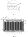
FIG. 1 is a schematic structural diagram of an electrochemical apparatus according to a first embodiment of this application; -
FIG. 2 is an enlarged view of position A shown inFIG. 1 ; -
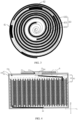
FIG. 3 is a cross-sectional diagram of an electrode assembly of the electrochemical apparatus shown inFIG. 1 , observed in a first direction; -
FIG. 4 is a schematic structural diagram of an electrochemical apparatus according to a second embodiment of this application; -
FIG. 5 is an enlarged view of position B shown inFIG. 4 ; -
FIG. 6 is a schematic structural diagram of an electrochemical apparatus according to a third embodiment of this application; -
FIG. 7 is an enlarged view of position C shown inFIG. 6 ; -
FIG. 8 is a schematic structural diagram of an electrochemical apparatus according to a fourth embodiment of this application; -
FIG. 9 is an enlarged view of position D shown inFIG. 8 ; and -
FIG. 10 is a schematic block diagram of an electric apparatus according to a fifth embodiment of this application. - The following clearly and completely describes the technical solutions in the embodiments of this application with reference to the accompanying drawings. Apparently, the described embodiments are only some rather than all of the embodiments of this application. The following description of at least one exemplary embodiment is merely illustrative and definitely is not construed as any limitation on this application or on use of this application. All other embodiments obtained by a person having ordinary skill in the art based on the embodiments of this application without creative efforts shall fall within the protection scope of this application.
- The technologies, methods, and devices known to those having ordinary skill in the related arts may not be discussed in detail, but where appropriate, the technologies, methods, and devices should be regarded as being authorized as a part of the description.
- In the descriptions of this application, it should be noted that, the orientations or positional relationships indicated by the orientation terms "front", "rear", "upper", "lower", "left", "right", "transverse, vertical, perpendicular, horizontal", and "top, bottom", and the like are merely intended for ease and brevity of the description of this application rather than indicating or implying that the apparatuses or components mentioned must have specific orientations, or must be constructed or manipulated according to specific orientations, and therefore shall not be construed as any limitations on embodiments of this application. Orientation terms "inside, outside" refer to the inside and outside of the contour of each component itself.
- In the descriptions of this application, it should be noted that, using words such as "first" and "second" to define components is merely for the purpose of distinguishing the components. Unless otherwise stated, the foregoing words do not have special meanings and cannot be construed as any limitations on the protection scope of this application.
- Referring to examples shown in
FIG. 1 and FIG. 2, FIG. 1 is a schematic structural diagram of anelectrochemical apparatus 1 according to an embodiment of this application, andFIG. 2 is an enlarged view of position A shown inFIG. 1 . Theelectrochemical apparatus 1 includes ahousing assembly 10, aconductor 30, aninsulator 20, and anelectrode assembly 40. Thehousing assembly 10 serves as a mounting support structure for all parts. Theconductor 30 is fixed to thehousing assembly 10 by using theinsulator 20. Theelectrode assembly 40 is mounted in thehousing assembly 10, and theelectrode assembly 40 is electrically connected to thehousing assembly 10 and theconductor 30 respectively, where thehousing assembly 10 and theconductor 30 are two poles, with opposite polarities, of theelectrochemical apparatus 1. - For ease of description, the coordinate system shown in
FIG. 1 is used to define directions. A coordinate axis H indicates a first direction. This direction is a height direction of theelectrochemical apparatus 1, a direction in which afirst housing 11 of thehousing assembly 10, theinsulator 20, and theconductor 30 are sequentially stacked, and also an axial direction of a first through-hole 11a of thefirst housing 11. A coordinate axis L indicates a second direction. This direction is a length direction or width direction of theelectrochemical apparatus 1, a direction in which asecond portion 32 of theconductor 30 extends outsides along a circumferential direction of thefirst portion 31, and also a radial direction of the first through-hole 11a of thefirst housing 11. As shown inFIG. 1 , the coordinate axis H is perpendicular to the coordinate axis L. - Based on the foregoing definition of directions, specific constructions of the
housing assembly 10, theconductor 30, theinsulator 20, and theelectrode assembly 40 are described below with reference to the implementations illustrated in the accompanying drawings. In the following descriptions, terms indicating the orientations or positional relationships, such as "upper", "lower", "top", and "bottom" are used with regard to the first direction H. Moreover, in absence of conflicts, the technical features involved in different implementations of this application may be combined. - Regarding the
housing assembly 10, thehousing assembly 10 includes afirst housing 11 and asecond housing 12 that fits with thefirst housing 11. Thefirst housing 11 and thesecond housing 12 are connected in a sealed manner and define anaccommodating space 10a therebetween. Theaccommodating space 10a is used to accommodate theelectrode assembly 40. Thefirst housing 11 is not only used for electrical connection with theelectrode assembly 40, but also for connecting with and fixing theinsulator 20. Thefirst housing 11 is provided with a first through-hole 11a. The first through-hole 11a runs through a surface of thefirst housing 11 facing theaccommodating space 10a and a surface of thefirst housing 11 away from theaccommodating space 10a. - As shown in
FIG. 1 , in an embodiment of this application, both thefirst housing 11 and thesecond housing 12 are made of a conductive material, for example, a conductive metal, a conductive composite material, or a conductive polymer material, etc. Thefirst housing 11 is approximately of a lid structure. The first through-hole 11a is provided in the middle part of thefirst housing 11. Thesecond housing 12 is approximately of a cylinder structure with an opening on the top. Thefirst housing 11 may be fixed to an end portion on the cylinder wall of thesecond housing 12 by means of welding, bonding with a sealant, or clamping, so as to seal the opening on the top of thesecond housing 12. In this way, theaccommodating space 10a is formed between thefirst housing 11 and thesecond housing 12. It can be understood that a shape of thehousing assembly 10 may be adjusted based on actual needs of use. For example, in some other embodiments of this application, thehousing assembly 10 may also be in the shape of a regular polyhedron such as a prism, a pyramid, or a cylindroid, etc. It can also be understood that the first through-hole 11a of thefirst housing 11 is not limited to the round shape shown inFIG. 1 . The first through-hole 11a may also be in a regular shape or an irregular shape, which is not specifically limited in this embodiment of this application. - Furthermore, in the embodiment illustrated in
FIG. 1 , theelectrochemical apparatus 1 is a hard-shell electrochemical apparatus. The hard-shell electrochemical apparatus is a type of electrochemical apparatus different from a soft-shell electrochemical apparatus, and has features such as high hardness and high mechanical strength. Specifically, both thefirst housing 11 and thesecond housing 12 may be made of a metal conductive material. For example, thefirst housing 11 and/or thesecond housing 12 may be made of steel alloy, aluminum alloy, iron alloy, copper alloy, or nickel alloy. - Alternatively, the
first housing 11 of thehousing assembly 10 is still made of a metal conductive material, and thesecond housing 12 may be made of plastic resistant to electrolyte corrosion. Thefirst housing 11 may be fixed to thesecond housing 12 by means of bonding with a sealant or clamping with a buckle structure, implementing a sealed connection therebetween. Specifically, a material resistant to electrolyte corrosion may be polystyrene, polypropylene, polyethylene, polyester, polyvinyl chloride, polyimide, acrylonitrile butadiene styrene plastic, polycarbonate, or polyamide. For example, thesecond housing 12 is made of polypropylene. - Regarding the
insulator 20, theinsulator 20 connects and fixes theconductor 30 to thefirst housing 11 of thehousing assembly 10, but also to insulate both, and communicates theaccommodating space 10a of thehousing assembly 10 with the outside when a temperature threshold is exceeded. It should also be noted that theconductor 30 is fixed to thefirst housing 11 of thehousing assembly 10 through theinsulator 20 and seal the first through-hole 11a of thefirst housing 11. Therefore, theinsulator 20 also plays a role in sealing a gap between theconductor 30 and thefirst housing 11, and the gap communicates with the outside via the first through-hole 11a. - As shown in
FIG. 2 , in an embodiment of this application, the shape of theinsulator 20 matches the shape of thefirst portion 31 of theconductor 30. Theinsulator 20 includes afirst insulation layer 21 and asecond insulation layer 22 attached to thefirst insulation layer 21. Thefirst insulation layer 21 is bonded to a surface of thefirst housing 11 facing theaccommodating space 10a, and thesecond insulation layer 22 is bonded to thefirst portion 31 of theconductor 30. Theinsulator 20 is provided with a second through-hole (not shown in the figure) that runs through thefirst insulation layer 21 and thesecond insulation layer 22. A shape of the second through-hole may be the same as or different from that of the first through-hole 11a of thefirst housing 11, which is not specifically limited herein. Both the second through-hole and the first through-hole 11a of thefirst housing 11 are used to expose thefirst portion 31 of theconductor 30. It is worth mentioning that to ensure thefirst portion 31 of theconductor 30 is exposed in the first through-hole 11a and the second through-hole, it needs to be satisfied that in the first direction H, a projection of theconductor 30 covers the first through-hole 11a and the second through-hole and at least partially falls inside the first through-hole 11a and the second through-hole simultaneously. In other words, the first through-hole and the second through-hole at least partially overlap when viewed along the first direction. In this way, on the premise of ensuring the sealing ofelectrochemical apparatus 1, a load of the electrical apparatus can sequentially pass through the first through-hole 11a of thefirst housing 11 and the second through-hole of theinsulator 20 and is then electrically connected to thefirst portion 31 of theconductor 30. Thefirst insulation layer 21 has a first melting point Tm (1) and thesecond insulation layer 22 has a second melting point Tm (2), where 0°C<Tm (2)-Tm (1)≤100°C. - Furthermore, in the embodiment illustrated in the figure, a material of the
insulator 20 includes acrylic modified resin, polyethylene, polyhydroxyacetyl ethylene diamine, modified polyolefin resin, polyolefin, polyvinyl chloride, fluororubber, other polyolefins and copolymers thereof. - Regarding the
conductor 30, as shown inFIG. 1 and FIG. 2 , in this embodiment of this application, theconductor 30 is located in theaccommodating space 10a of thehousing assembly 10, and theconductor 30 has thefirst portion 31. Approximately in a disc-shaped structure, thefirst portion 31 is fixed to the surface of thefirst housing 11 facing theaccommodating space 10a through theinsulator 20, and covers the entire first through-hole 11a of thefirst housing 11. A surface offirst portion 31 located in the first through-hole 11a is used for electrical connection with the load of the electric apparatus, and a surface of thefirst portion 31 away from theaccommodating space 10a is used for electrical connection with one pole of theelectrode assembly 40. - For ease of electrical connection between the
electrochemical apparatus 1 and the load of the electric apparatus, theconductor 30 may further have athird portion 33 that is coaxial with thefirst portion 31. Thethird portion 33 is a convex structure of theconductor 30 accommodated in the first through-hole 11a. For example, thethird portion 33 is formed by projecting a surface of thefirst portion 31 having no contact with theinsulator 20 towards the first through-hole 11a. It can be understood that the construction of thethird portion 33 is not specifically limited herein. For example, thethird portion 33 may pass through the first through-hole 11a of thefirst housing 11 and extends out of thehousing assembly 10, or thethird portion 33 is exposed inside the first through-hole 11a. Certainly, thethird portion 33 may be not disposed from the perspective of saving the manufacturing cost ofelectrochemical apparatus 1. In this case, the load of the electric apparatus sequentially passes through the first through-hole 11a of thefirst housing 11 and the second through-hole of theinsulator 20, and is electrically connected to the surface, of thefirst portion 31 of theconductor 30, having no contact with theinsulator 20. - As shown in
FIG. 4 andFIG. 5 , in another embodiment of this application, theconductor 30 is located outside theaccommodating space 10a of thehousing assembly 10, and theconductor 30 has thefirst portion 31 and thethird portion 33 that are coaxial. In the shape of a disc, thefirst portion 31 is fixed to the surface of thefirst housing 11 away from theaccommodating space 10a through theinsulator 20, and covers the entire first through-hole 11a of thefirst housing 11. Thethird portion 33 is formed by extending the surface of thefirst portion 31 inside the first through-hole 11a towards theaccommodating space 10a. Fixed through theinsulator 20, a surface of thethird portion 33 facing theaccommodating space 10a is used for electrical connection with theelectrode assembly 40. - Furthermore, in the embodiment illustrated by the figures, the
conductor 30 may be made of a metal conductive material. Specifically, theconductor 30 may be made of steel alloy, aluminum alloy, iron alloy, copper alloy, nickel alloy, or the like. For example, theconductor 30 is made of an iron-carbon alloy (namely, stainless steel) or aluminum. - Regarding the
electrode assembly 40, theelectrode assembly 40 is a core component for charging and discharging theelectrochemical apparatus 1. As shown inFIG. 3 , in this embodiment of this application, theelectrode assembly 40 includes afirst tab 41, asecond tab 42, and abare battery cell 43. Thebare battery cell 43 is accommodated in theaccommodating space 10a of thehousing assembly 10, and includes a first electrode plate 431, asecond electrode plate 432, and a separator 433 that are stacked. The separator 433 separates the first electrode plate 431 from thesecond electrode plate 432. After being wound, the first electrode plate 431, thesecond electrode plate 432, and the separator 433 together form a cylinder structure. An axial direction for winding thebare battery cell 43 is parallel to the first direction H. One end of thefirst tab 41 is electrically connected to a current collector of the first electrode plate 431, and another end of thefirst tab 41 is electrically connected to thefirst portion 31 and thesecond portion 32 of theconductor 30. One end of thesecond tab 42 is electrically connected to a current collector of thesecond electrode plate 432, and another end of thesecond tab 42 is electrically connected to thefirst housing 11 of thehousing assembly 10. One of the first electrode plate 431 and thesecond electrode plate 432 is a positive electrode plate and the other one is a negative electrode plate. Certainly, in some other embodiments, thebare battery cell 43 may also be a stacked structure. The specific structure of thebare battery cell 43 is not limited in this application. In addition, theelectrochemical apparatus 1 includes an electrolyte filled in theaccommodating space 10a, and thebare battery cell 43 is immersed in the electrolyte. It can be understood that when thefirst housing 11 and thesecond housing 12 of thehousing assembly 10 are both made of a conductive metal material and are electrically connected, the another end of thesecond tab 42 of theelectrode assembly 40 is not limited to being electrically connected to thefirst housing 11, but may also be electrically connected to thesecond housing 12. The way how the another end of thesecond tab 42 is connected to thefirst housing 11 and/or thesecond housing 12 is not specifically limited in this embodiment of this application. - A pressure relieving theory of the
electrochemical apparatus 1 is described below. Generally, theelectrochemical apparatus 1 relieves pressure in the following way. Fixed by theinsulator 20, thefirst portion 31 of theconductor 30 is tightly attached to thefirst housing 11 of thehousing assembly 10. Theinsulator 20 is located between thefirst portion 31 of theconductor 30 and thefirst housing 11 and seals the gap therebetween, so as to isolate theaccommodating space 10a of thehousing assembly 10 from the outside. In this case, theaccommodating space 10a of thehousing assembly 10 is under a normal reaction temperature and pressure, so the normal reaction temperature does not exceed the first melting point of thefirst insulation layer 21 of theinsulator 20, and thefirst insulation layer 21 of theinsulator 20 is in a solid state. - When thermal runaway occurs in the
electrochemical apparatus 1, the temperature in theaccommodating space 10a of thehousing assembly 10 exceeds the first melting point of thefirst insulation layer 21. For example, the first melting point of thefirst insulation layer 21 is 130°C, and thefirst insulation layer 21 of theinsulator 20 melts from the solid state to a liquid state when the temperature exceeds the first melting point. In this case, the bonding force between theconductor 30 and thefirst housing 11 continues to decrease, and the pressure inside theaccommodating space 10a continues to increase. When the pressure inside theaccommodating space 10a exceeds a threshold of bonding strength between theconductor 30 and thefirst housing 11, a crack is caused between theconductor 30 and thefirst housing 11. The crack communicates with the outside via the first through-hole 11a to form a pressure relieving passage, and both heat and gas in theaccommodating space 10a can be discharged through the pressure relieving passage, achieving safe use of theelectrochemical apparatus 1. - In conclusion, for the
electrochemical apparatus 1 according to the embodiments of this application: on one hand, thefirst insulation layer 21 with a lower melting point is disposed on a side of theinsulator 20 close to thehousing assembly 10. When thermal runaway occurs in theelectrochemical apparatus 1, the temperature in theaccommodating space 10a of thehousing assembly 10 exceeds the first melting point of thefirst insulation layer 21, thefirst insulation layer 21 melts from a solid state to a liquid state, so that the high-pressure gas in theaccommodating space 10a can easily break through thefirst insulation layer 21 and is discharged to the outside via the first through-hole 11a. Theinsulator 20 can achieve the purpose of pressure relief and explosion prevention, and it is unnecessary to arrange an extra anti-explosion device on thehousing assembly 10 of theelectrochemical apparatus 1, thereby mitigating the technical problem that the structural stability of the electrochemical apparatus is affected by explosion prevention and pressure relief through indentation. On the other hand, thesecond insulation layer 22 with a higher melting point is disposed on a side of theinsulator 20 close to theconductor 30. During packaging of theconductor 30 and thehousing assembly 10, a heat sealing temperature is between the first melting point of thefirst insulation layer 21 and the second melting point of thesecond insulation layer 22. Therefore, theinsulator 20 still has a specific hardness to prevent blurs of thehousing assembly 10 and theconductor 30 from piercing through itself, thereby reducing short circuits caused by blurs of thehousing assembly 10 and theconductor 30 piercing through theinsulator 20. - Referring to examples shown in
FIG. 6 andFIG. 7 , theconductor 30 has asecond portion 32 that is coaxial with the first portion. Thesecond portion 32 is formed by extending periphery of an end, of thefirst portion 31, away from theinsulator 20 along a circumferential direction. A thickness H1 of thefirst portion 31 in the first direction H is greater than a thickness H2 of thesecond portion 32 in the first direction H. Fixed by theinsulator 20, thesecond portion 32 and thefirst housing 11 are arranged opposite each other, and a gap is provided therebetween for communicating with theaccommodating space 10a of thehousing assembly 10. Both thesecond portion 32 and thefirst portion 31 of theconductor 30 are used for electrical connection with theelectrode assembly 40. In this way, when thermal runaway occurs in theelectrochemical apparatus 1, both thefirst housing 11 ofhousing assembly 10 and thesecond portion 32 ofconductor 30 suffer from gas pressure within theaccommodating space 10a. Therefore, theconductor 30 is under a force of running away from thehousing assembly 10, reducing the gas pressure required for breaking thefirst insulation layer 21 of theinsulator 20. This facilitates detaching theconductor 30 from thefirst housing 11, and makes a heat dissipation and exhaust rate higher than an internal system runaway rate, further improving the safety and reliability of theelectrochemical apparatus 1. It should be noted that: thefirst portion 31 of theconductor 30 covering the entire first through-hole 11a of thefirst housing 11 specifically means that observed in the first direction H, a projection of the first through-hole 11a of thefirst housing 11 onto thefirst portion 31 falls within thefirst portion 31 of theconductor 30. - Further, the thickness H1 of the
first portion 31 and the thickness H2 of thesecond portion 32 satisfy that: 0.3≤H2/H1≤0.8. In other words, when the ratio of H2 to H1 is less than 0.3, the second portion is relatively thin. In this case, the difficulty of manufacturing andprocessing conductor 30 is increased, causing a lower yield rate of theconductor 30 and a decrease in the mechanical strength of this part. As a result, theconductor 30 tends to bend under high pressure, causing functional failure of thesecond portion 32. To be specific, it is difficult to detach theconductor 30 from thefirst housing 11 under acting force of the high-pressure gas. When the ratio of H2 to H1 is greater than 0.8, a spacing between thesecond portion 32 and thefirst housing 11 is small, short circuit is more easily caused by contact between thesecond portion 32 and thefirst housing 11. For example, the thickness H1 of thefirst portion 31 of theconductor 30 is 0.15 mm, and the thickness H2 of thesecond portion 32 of theconductor 30 is 0.07 mm. - Further, in the first direction H, an area of the projection of the
conductor 30 is S1, an area of the projection of thefirst portion 31 of theconductor 30 is S2, and 0.5≤S2/S1≤0.7. In other words, when the ratio of S2 to S1 is less than 0.5, the ultimate bonding strength between theconductor 30 and theinsulator 20 will inevitably decrease due to a limited area of contact therebetween. In this case, it is difficult to ensure an effective area of packaging of thefirst portion 31 of theconductor 30 and thefirst housing 11, impairing the sealing between theconductor 30 and thefirst housing 11. When the ratio of S2 to S1 is greater than 0.7, thesecond portion 32 ofconductor 30 occupies a smaller area. Under high pressure conditions, theconductor 30 is restricted from detaching from thehousing assembly 10, thereby increasing the pressure relief threshold of the electrochemical apparatus. - To ensure safety and control waste of performance while reducing the material cost, further, 10°C≤Tm (2)-Tm (1)≤80°C. When a difference in melting points between the
first insulation layer 21 and thesecond insulation layer 22 is small, for example, less than 10°C, thefirst insulation layer 21 will still melt to form a pressure relieving passage, but a melting temperature of thefirst insulation layer 21 is close to that of thesecond insulation layer 22. In the case of thermal runaway in theelectrochemical apparatus 1, if thefirst insulation layer 21 fails to melt and form a pressure relieving passage in a timely manner, the temperature in theelectrochemical apparatus 1 will continue to rise and easily reach the melting temperature of thesecond insulation layer 22, leaving an insufficient safety margin. When the difference in melting points between thefirst insulation layer 21 and thesecond insulation layer 22 is large, for example, greater than 80°C, the safety margin is excessively large, causing performance waste and cost increase. When the difference in melting points between thefirst insulation layer 21 and thesecond insulation layer 22 is within the foregoing numerical range, the difference in melting points between thefirst insulation layer 21 and thesecond insulation layer 22 is relatively small, and less time is needed to melt only thefirst insulation layer 21. In this case, a pressure relieving passage can be formed in a timely manner between theaccommodating space 10a of thehousing assembly 10 and the outside, thereby leaving a sufficient safety margin and reducing material costs. - To reduce the packaging difficulty and manufacturing costs of the electrochemical apparatus, preferably, 30°C≤Tm (2)-Tm (1)≤60°C. According to packaging of the electrochemical apparatus, the
first insulation layer 21 and thesecond insulation layer 22 can be thermally bonded to thefirst housing 11 and theconductor 30 respectively only when the temperature is raised to be higher than a composite temperature at which thesecond insulation layer 22 melts. If the difference in melting points between thefirst insulation layer 21 and thesecond insulation layer 22 is excessively large, fluidity of thefirst insulation layer 21 is relatively high at the composite temperature, and serious glue overflow will occur. In addition to increasing the packaging difficulty and manufacturing costs, glue overflow will also invade the internal space of the electrochemical apparatus, and causes problems such as short circuit due to a pierced insulation glue or separator in the electrode assembly in the case of drop, impact, and the like. To improve the bonding performance of theinsulator 20 and further reduce the packaging difficulty of thefirst housing 11 and theconductor 30, further, in the first direction H, a ratio of a thickness T1 of thefirst insulation layer 21 to a thickness T2 of thesecond insulation layer 22 T1:T2 is (0.5-1.5):(1.5-3.5). For example, 10 µm≤T1≤30 µm. With the thickness being in this numerical range, thefirst insulation layer 21 provides good adhesion and is thinner. And 60 µm≤T2≤90 µm, with the thickness being in this numerical range, thesecond insulation layer 22 can be kept stable and undeformed and has appropriate hardness and flexibility, which is conducive to packaging of thefirst housing 11 and theconductor 30. - To improve the performance of bonding between the
insulator 20 and theconductor 30 and reduce the packaging difficulty of thefirst housing 11 and theconductor 30, as shown inFIG. 8 andFIG. 9 , theinsulator 20 may further include athird insulation layer 23 that is attached to a surface of thesecond insulation layer 22 away from thefirst insulation layer 21. In this case, thefirst insulation layer 21, thesecond insulation layer 22, and thethird insulation layer 23 are integrally formed, Thesecond insulation layer 22 is bonded to thefirst portion 31 of theconductor 30 through thethird insulation layer 23, and the second through-hole runs through thethird insulation layer 23 accordingly. Thethird insulation layer 23 has a third melting point Tm (3), and 0°C<Tm (3)-Tm (2)≤100°C. Because the melting points of thethird insulation layer 23 and thefirst insulation layer 21 are both lower than the melting point of thesecond insulation layer 22, thefirst insulation layer 21 and thethird insulation layer 23 can be thermally bonded to thefirst housing 11 and theconductor 30 respectively only when the composite temperature is raised to be higher than a composite temperature at which thethird insulation layer 23 melts. Compared with theinsulator 20 where thefirst insulation layer 21 and thesecond insulation layer 22 are integrally formed, this further mitigates the problem of serious glue overflow caused by a high fluidity of thefirst insulation layer 21 at the composite temperature. In addition, the third insulation layer is preferably made of a material that is the same for the first insulation layer. - The
electrochemical apparatus 1 may be manufactured using the following method. - Design of the insulator 20: the
insulator 20 is an integrated structure that is formed by sequentially stacking thefirst insulation layer 21, thesecond insulation layer 22, and thethird insulation layer 23, with a total thickness of 150 µm and a thickness ratio of the first insulation layer 21:the second insulation layer 22:thethird insulation layer 23 being 1:3:1. The melting point range of thefirst insulation layer 21 and thethird insulation layer 23 is 100°C-130°C. For example, thefirst insulation layer 21 and thethird insulation layer 23 have the same melting point of 123°C and are made of modified polypropylene resin. The melting point range of thesecond insulation layer 22 is 130°C-180°C. For example, thesecond insulation layer 22 has a melting point of 165°C and is made of polypropylene. - Design of the conductor 30: the
conductor 30 is a conductive metal structure integrally formed by thefirst portion 31, thesecond portion 32, and thethird portion 33. Thefirst portion 31 has a diameter of 5.3±0.05 mm and a thickness of 0.15±0.015 mm, thesecond portion 32 has a diameter of 8.3±0.05 mm and a thickness of 0.07±0.015 mm, and thethird portion 33 has a diameter of 3±0.05 mm and a thickness of 0.53±0.02 mm. - The
housing assembly 10 and theconductor 30 are connected and fixed through theinsulator 20. Thefirst housing 11 has a diameter of 10.03±0.04 mm and a thickness of 0.2 (+0.02/-0.01) mm. A hot pressing temperature is 125±20°C, hot pressing pressure is 60±30 Kg, and hot pressing time is 5-15s. When the hot pressing temperature reaches the melting point of thefirst insulation layer 21 and thethird insulation layer 23, the two melt and are bonded with thefirst housing 11 and thefirst portion 31 of theconductor 30 respectively, so as to complete the packaging of theconductor 30 and thehousing assembly 10. - No improvement is provided regarding the preparation and assembly methods of the
electrode assembly 40 and other parts. Details are not repeated herein. - Based on the same technical conception, refer to the example illustrated in
FIG. 10. FIG. 10 is a schematic block diagram of an electric apparatus according to an embodiment of this application. The electric apparatus includes theelectrochemical apparatus 1 provided in the foregoing solution, and theelectrochemical apparatus 1 is used to supply electric energy for the electric apparatus. It can be understood that the electric apparatus according to this embodiment of this application is not specifically limited. The foregoing electric apparatus may include but is not limited to a notebook computer, a pen-input computer, a mobile computer, an electronic book player, a portable telephone, a portable fax machine, a portable copier, a portable printer, a stereo headset, a video recorder, a liquid crystal television, a portable cleaner, a portable CD player, a mini-disc, a transceiver, an electronic notepad, a calculator, a memory card, a portable recorder, a radio, a standby power source, a motor, an electric vehicle, an automobile, a motorcycle, a power-assisted bicycle, a bicycle, a lighting appliance, a toy, a game console, a clock, an electric tool, a flash lamp, a camera, a large household power-storingelectrochemical apparatus 1, a lithium-ion capacitor, or the like. - The foregoing descriptions are merely some embodiments of this application, but are not intended to limit the patent scope of this application. Any equivalent structure or equivalent process transformations made using the descriptions and accompanying drawings of this application, or directly or indirectly applied in other related technical fields, are equally included in the scope of patent protection of this application.
Claims (12)
- An electrochemical apparatus (1), comprising an electrode assembly (40), a housing assembly (10), a conductor (30), and an insulator (20); characterized in that,the electrode assembly (40) comprises a first tab (41);the housing assembly (10) comprises a first housing (11) and a second housing (12);the first housing (11) and the second housing (12) define an accommodating space (10a) and the electrode assembly (40) is accommodated in the accommodating space (10a);the first tab (41) is electrically connected to the conductor (30);the insulator (20) is located between the first housing (11) and the conductor (30) ;the first housing (11) has a first through-hole (11a);the insulator (20) has a second through-hole;in a first direction (H), a projection of the conductor (30) covers the first through-hole (11a) and the second through-hole;the first through-hole (11a) and the second through-hole at least partially overlap when viewed along the first direction; characterized in that,the first direction (H) is an axial direction of the first through-hole (11a);the insulator (20) comprises a first insulation layer (21) and a second insulation layer (22);the first insulation layer (21) is attached to the first housing (11) and located between the first housing (11) and the second insulation layer (22);the first insulation layer (21) comprises at least one selected from the group consisting of acrylic modified resin, polyethylene, polypropylene, polyhydroxyacetyl ethylene diamine, and modified polyolefin resin;the first insulation layer (21) has a first melting point Tm (1);the second insulation layer (22) comprises at least one selected from the group consisting of acrylic modified resin, polyethylene, polyhydroxyacetyl ethylene diamine, modified polyolefin resin, polyolefin, polyvinyl chloride, fluororubber, other polyolefins and copolymers thereof;the second insulation layer (22) has a second melting point Tm (2); characterized in that, 0°C<Tm (2)-Tm (1)≤100°C.
- The electrochemical apparatus (1) according to claim 1, characterized in that, 10°C≤Tm (2)-Tm (1)≤80°C.
- The electrochemical apparatus (1) according to claim 2, characterized in that, 30°C≤Tm (2)-Tm (1)≤60°C.
- The electrochemical apparatus (1) according to any one of claims 1-3, characterized in that, in the first direction (H), a ratio of a thickness T1 of the first insulation layer (21) to a thickness T2 of the second insulation layer (22) T1:T2 is (0.5-1.5):(1.5-3.5).
- The electrochemical apparatus (1) according to any one of claims 1-4, characterized in that,the insulator (20) further comprises a third insulation layer (23);the third insulation layer (23) is attached between the conductor (30) and the second insulation layer (22); andthe third insulation layer (23) has a third melting point Tm (3), characterized in that, 0°C<Tm (2)-Tm (3)≤100°C.
- The electrochemical apparatus (1) according to claim 5, characterized in that,100°C≤Tm (1)≤130°C;100°C≤Tm (3)≤130°C; and130°C<Tm (2)≤180°C.
- The electrochemical apparatus (1) according to claim 5 or 6, characterized in that,the thickness T1 of the first insulation layer (21) is 10 µm≤T1≤30 µm; anda thickness T3 of the third insulation layer (23) is 10 µm≤T3≤30 µm.
- The electrochemical apparatus (1) according to any one of claims 5-7, characterized in that, the third insulation layer (23) comprises at least one selected from the group consisting of acrylic modified resin, polyethylene, polypropylene, polyhydroxyacetyl ethylene diamine, and modified polyolefin resin.
- The electrochemical apparatus (1) according to any one of claims 1-8, characterized in that,the conductor (30) is located in the accommodating space (10a);the conductor (30) comprises a first portion (31) and a second portion (32);the insulator (20) is connected to the first portion (31);the second portion (32) is connected to an edge of the first portion (31); andin the first direction (H), a thickness of the first portion (31) is H1 and a thickness of the second portion (32) is H2, characterized in that, H1>H2.
- The electrochemical apparatus (1) according to claim 9, characterized in that,0.3≤H2/H1≤0.8.
- The electrochemical apparatus (1) according to claim 9, characterized in that, in the first direction (H), an area of the projection of the conductor (30) is S 1, an area of a projection of the first portion (31) is S2, and 0.5≤S2/S1≤0.7.
- An electric apparatus, comprising the electrochemical apparatus (1) according to any one of claims 1 to 11.
Applications Claiming Priority (1)
| Application Number | Priority Date | Filing Date | Title |
|---|---|---|---|
| CN202211420609.5A CN115498354B (en) | 2022-11-14 | 2022-11-14 | Electrochemical device and power utilization device |
Publications (2)
| Publication Number | Publication Date |
|---|---|
| EP4369483A2 true EP4369483A2 (en) | 2024-05-15 |
| EP4369483A3 EP4369483A3 (en) | 2024-07-31 |
Family
ID=85115641
Family Applications (1)
| Application Number | Title | Priority Date | Filing Date |
|---|---|---|---|
| EP23209461.5A Pending EP4369483A3 (en) | 2022-11-14 | 2023-11-13 | Electrochemical apparatus and electric apparatus |
Country Status (3)
| Country | Link |
|---|---|
| US (1) | US20240162541A1 (en) |
| EP (1) | EP4369483A3 (en) |
| CN (1) | CN115498354B (en) |
Cited By (1)
| Publication number | Priority date | Publication date | Assignee | Title |
|---|---|---|---|---|
| EP4651252A1 (en) * | 2024-05-16 | 2025-11-19 | Ningde Amperex Technology Ltd. | Battery cell and electrical device |
Families Citing this family (3)
| Publication number | Priority date | Publication date | Assignee | Title |
|---|---|---|---|---|
| CN119786874A (en) * | 2022-12-31 | 2025-04-08 | 宁德新能源科技有限公司 | Pressure relief mechanism, battery cell and electrical device |
| KR20250149456A (en) * | 2024-04-09 | 2025-10-16 | 삼성에스디아이 주식회사 | Button cell |
| CN223156238U (en) * | 2024-08-09 | 2025-07-25 | 宁德时代新能源科技股份有限公司 | Battery monomer, battery device and electric equipment |
Family Cites Families (9)
| Publication number | Priority date | Publication date | Assignee | Title |
|---|---|---|---|---|
| CN209087921U (en) * | 2018-12-05 | 2019-07-09 | 宁德时代新能源科技股份有限公司 | Top cover assembly and secondary battery |
| US11011805B2 (en) * | 2019-03-28 | 2021-05-18 | Medtronic, Inc. | Electrode |
| WO2021112084A1 (en) * | 2019-12-04 | 2021-06-10 | 株式会社村田製作所 | Secondary battery |
| EP4080670A4 (en) * | 2019-12-18 | 2023-08-02 | SANYO Electric Co., Ltd. | CYLINDRICAL BATTERY |
| KR20210156608A (en) * | 2020-06-18 | 2021-12-27 | 삼성에스디아이 주식회사 | Secondary battery |
| CN214898616U (en) * | 2021-10-21 | 2021-11-26 | 浙江锂威能源科技有限公司 | A shell assembly and button battery |
| CN216362147U (en) * | 2021-11-04 | 2022-04-22 | 东莞锂微电子科技有限公司 | A high-safety battery and its cover plate assembly |
| CN114628827A (en) * | 2022-05-12 | 2022-06-14 | 比亚迪股份有限公司 | Battery, battery pack and vehicle |
| CN115832638B (en) * | 2022-08-16 | 2025-03-18 | 宁德新能源科技有限公司 | Electrochemical devices and electronic devices |
-
2022
- 2022-11-14 CN CN202211420609.5A patent/CN115498354B/en active Active
-
2023
- 2023-11-09 US US18/388,219 patent/US20240162541A1/en active Pending
- 2023-11-13 EP EP23209461.5A patent/EP4369483A3/en active Pending
Cited By (1)
| Publication number | Priority date | Publication date | Assignee | Title |
|---|---|---|---|---|
| EP4651252A1 (en) * | 2024-05-16 | 2025-11-19 | Ningde Amperex Technology Ltd. | Battery cell and electrical device |
Also Published As
| Publication number | Publication date |
|---|---|
| CN115498354A (en) | 2022-12-20 |
| CN115498354B (en) | 2023-03-03 |
| EP4369483A3 (en) | 2024-07-31 |
| US20240162541A1 (en) | 2024-05-16 |
Similar Documents
| Publication | Publication Date | Title |
|---|---|---|
| US20240162541A1 (en) | Electrochemical apparatus and electric apparatus | |
| EP3989352B1 (en) | Secondary battery, battery module, and device using battery as power supply | |
| US20230031705A1 (en) | Electrochemical device and electronic device | |
| JP7490761B2 (en) | Top cover assembly, secondary battery, battery module and device | |
| US8268463B2 (en) | Secondary battery and method of fabricating the same | |
| EP2866281B1 (en) | Rechargeable battery having fuse unit | |
| US20230395931A1 (en) | End cover assembly, battery cell, battery, and electric apparatus | |
| EP2079126A1 (en) | Impact Resistant Battery Pack | |
| US9345146B2 (en) | Circuit board for secondary battery and secondary battery with the circuit board | |
| JP2009146879A (en) | Protection circuit board and battery pack having the same | |
| US20260094843A1 (en) | Battery cell and electric device | |
| CN216213745U (en) | Square secondary battery's top cap and secondary battery | |
| US20090085518A1 (en) | Protective circuit board and battery pack using the same | |
| CN218975498U (en) | Batteries and Electronics | |
| US20250167355A1 (en) | Secondary battery and electronic device | |
| EP4459758A1 (en) | Battery and electric device | |
| JP4499648B2 (en) | Lithium ion secondary battery | |
| WO2018212447A1 (en) | Secondary battery | |
| US20230261335A1 (en) | Battery and electronic device having same | |
| KR20050110460A (en) | Secondary battery and electrodes assembly using the same | |
| US20250266488A1 (en) | Battery and electronic apparatus | |
| WO2024182945A1 (en) | Battery cell, battery, electric device, and assembly method for battery cell | |
| JP7359849B2 (en) | Batteries and electrical equipment equipped with them | |
| WO2026001902A1 (en) | Battery cell and electrical device | |
| KR101308260B1 (en) | Secondary battery |
Legal Events
| Date | Code | Title | Description |
|---|---|---|---|
| PUAI | Public reference made under article 153(3) epc to a published international application that has entered the european phase |
Free format text: ORIGINAL CODE: 0009012 |
|
| STAA | Information on the status of an ep patent application or granted ep patent |
Free format text: STATUS: REQUEST FOR EXAMINATION WAS MADE |
|
| 17P | Request for examination filed |
Effective date: 20231113 |
|
| AK | Designated contracting states |
Kind code of ref document: A2 Designated state(s): AL AT BE BG CH CY CZ DE DK EE ES FI FR GB GR HR HU IE IS IT LI LT LU LV MC ME MK MT NL NO PL PT RO RS SE SI SK SM TR |
|
| PUAL | Search report despatched |
Free format text: ORIGINAL CODE: 0009013 |
|
| AK | Designated contracting states |
Kind code of ref document: A3 Designated state(s): AL AT BE BG CH CY CZ DE DK EE ES FI FR GB GR HR HU IE IS IT LI LT LU LV MC ME MK MT NL NO PL PT RO RS SE SI SK SM TR |
|
| RIC1 | Information provided on ipc code assigned before grant |
Ipc: H01M 50/188 20210101ALI20240621BHEP Ipc: H01M 50/564 20210101ALI20240621BHEP Ipc: H01M 50/559 20210101ALI20240621BHEP Ipc: H01M 50/553 20210101ALI20240621BHEP Ipc: H01M 50/545 20210101ALI20240621BHEP Ipc: H01M 50/375 20210101ALI20240621BHEP Ipc: H01M 50/342 20210101ALI20240621BHEP Ipc: H01M 50/198 20210101ALI20240621BHEP Ipc: H01M 50/193 20210101ALI20240621BHEP Ipc: H01M 50/179 20210101ALI20240621BHEP Ipc: H01M 50/176 20210101ALI20240621BHEP Ipc: H01M 50/169 20210101ALI20240621BHEP Ipc: H01M 50/148 20210101ALI20240621BHEP Ipc: H01M 50/152 20210101ALI20240621BHEP Ipc: H01M 50/15 20210101ALI20240621BHEP Ipc: H01M 50/107 20210101ALI20240621BHEP Ipc: H01M 50/103 20210101AFI20240621BHEP |