EP4369465A1 - Energy storage device and electronic device - Google Patents
Energy storage device and electronic device Download PDFInfo
- Publication number
- EP4369465A1 EP4369465A1 EP23207382.5A EP23207382A EP4369465A1 EP 4369465 A1 EP4369465 A1 EP 4369465A1 EP 23207382 A EP23207382 A EP 23207382A EP 4369465 A1 EP4369465 A1 EP 4369465A1
- Authority
- EP
- European Patent Office
- Prior art keywords
- patch
- insulation
- sub
- jelly roll
- connection
- Prior art date
- Legal status (The legal status is an assumption and is not a legal conclusion. Google has not performed a legal analysis and makes no representation as to the accuracy of the status listed.)
- Granted
Links
Images


Classifications
-
- H—ELECTRICITY
- H01—ELECTRIC ELEMENTS
- H01M—PROCESSES OR MEANS, e.g. BATTERIES, FOR THE DIRECT CONVERSION OF CHEMICAL ENERGY INTO ELECTRICAL ENERGY
- H01M10/00—Secondary cells; Manufacture thereof
- H01M10/05—Accumulators with non-aqueous electrolyte
- H01M10/058—Construction or manufacture
- H01M10/0587—Construction or manufacture of accumulators having only wound construction elements, i.e. wound positive electrodes, wound negative electrodes and wound separators
-
- H—ELECTRICITY
- H01—ELECTRIC ELEMENTS
- H01M—PROCESSES OR MEANS, e.g. BATTERIES, FOR THE DIRECT CONVERSION OF CHEMICAL ENERGY INTO ELECTRICAL ENERGY
- H01M50/00—Constructional details or processes of manufacture of the non-active parts of electrochemical cells other than fuel cells, e.g. hybrid cells
- H01M50/50—Current conducting connections for cells or batteries
- H01M50/572—Means for preventing undesired use or discharge
- H01M50/584—Means for preventing undesired use or discharge for preventing incorrect connections inside or outside the batteries
- H01M50/59—Means for preventing undesired use or discharge for preventing incorrect connections inside or outside the batteries characterised by the protection means
- H01M50/593—Spacers; Insulating plates
-
- H—ELECTRICITY
- H01—ELECTRIC ELEMENTS
- H01M—PROCESSES OR MEANS, e.g. BATTERIES, FOR THE DIRECT CONVERSION OF CHEMICAL ENERGY INTO ELECTRICAL ENERGY
- H01M50/00—Constructional details or processes of manufacture of the non-active parts of electrochemical cells other than fuel cells, e.g. hybrid cells
- H01M50/50—Current conducting connections for cells or batteries
- H01M50/531—Electrode connections inside a battery casing
- H01M50/538—Connection of several leads or tabs of wound or folded electrode stacks
-
- H—ELECTRICITY
- H01—ELECTRIC ELEMENTS
- H01M—PROCESSES OR MEANS, e.g. BATTERIES, FOR THE DIRECT CONVERSION OF CHEMICAL ENERGY INTO ELECTRICAL ENERGY
- H01M10/00—Secondary cells; Manufacture thereof
- H01M10/05—Accumulators with non-aqueous electrolyte
- H01M10/052—Li-accumulators
-
- H—ELECTRICITY
- H01—ELECTRIC ELEMENTS
- H01M—PROCESSES OR MEANS, e.g. BATTERIES, FOR THE DIRECT CONVERSION OF CHEMICAL ENERGY INTO ELECTRICAL ENERGY
- H01M10/00—Secondary cells; Manufacture thereof
- H01M10/05—Accumulators with non-aqueous electrolyte
- H01M10/058—Construction or manufacture
- H01M10/0583—Construction or manufacture of accumulators with folded construction elements except wound ones, i.e. folded positive or negative electrodes or separators, e.g. with "Z"-shaped electrodes or separators
-
- H—ELECTRICITY
- H01—ELECTRIC ELEMENTS
- H01M—PROCESSES OR MEANS, e.g. BATTERIES, FOR THE DIRECT CONVERSION OF CHEMICAL ENERGY INTO ELECTRICAL ENERGY
- H01M10/00—Secondary cells; Manufacture thereof
- H01M10/42—Methods or arrangements for servicing or maintenance of secondary cells or secondary half-cells
- H01M10/44—Methods for charging or discharging
-
- H—ELECTRICITY
- H01—ELECTRIC ELEMENTS
- H01M—PROCESSES OR MEANS, e.g. BATTERIES, FOR THE DIRECT CONVERSION OF CHEMICAL ENERGY INTO ELECTRICAL ENERGY
- H01M50/00—Constructional details or processes of manufacture of the non-active parts of electrochemical cells other than fuel cells, e.g. hybrid cells
- H01M50/10—Primary casings; Jackets or wrappings
- H01M50/147—Lids or covers
- H01M50/148—Lids or covers characterised by their shape
- H01M50/15—Lids or covers characterised by their shape for prismatic or rectangular cells
-
- H—ELECTRICITY
- H01—ELECTRIC ELEMENTS
- H01M—PROCESSES OR MEANS, e.g. BATTERIES, FOR THE DIRECT CONVERSION OF CHEMICAL ENERGY INTO ELECTRICAL ENERGY
- H01M50/00—Constructional details or processes of manufacture of the non-active parts of electrochemical cells other than fuel cells, e.g. hybrid cells
- H01M50/40—Separators; Membranes; Diaphragms; Spacing elements inside cells
- H01M50/471—Spacing elements inside cells other than separators, membranes or diaphragms; Manufacturing processes thereof
-
- H—ELECTRICITY
- H01—ELECTRIC ELEMENTS
- H01M—PROCESSES OR MEANS, e.g. BATTERIES, FOR THE DIRECT CONVERSION OF CHEMICAL ENERGY INTO ELECTRICAL ENERGY
- H01M50/00—Constructional details or processes of manufacture of the non-active parts of electrochemical cells other than fuel cells, e.g. hybrid cells
- H01M50/40—Separators; Membranes; Diaphragms; Spacing elements inside cells
- H01M50/489—Separators, membranes, diaphragms or spacing elements inside the cells, characterised by their physical properties, e.g. swelling degree, hydrophilicity or shut down properties
- H01M50/494—Tensile strength
-
- H—ELECTRICITY
- H01—ELECTRIC ELEMENTS
- H01M—PROCESSES OR MEANS, e.g. BATTERIES, FOR THE DIRECT CONVERSION OF CHEMICAL ENERGY INTO ELECTRICAL ENERGY
- H01M50/00—Constructional details or processes of manufacture of the non-active parts of electrochemical cells other than fuel cells, e.g. hybrid cells
- H01M50/50—Current conducting connections for cells or batteries
- H01M50/572—Means for preventing undesired use or discharge
- H01M50/584—Means for preventing undesired use or discharge for preventing incorrect connections inside or outside the batteries
- H01M50/59—Means for preventing undesired use or discharge for preventing incorrect connections inside or outside the batteries characterised by the protection means
- H01M50/597—Protection against reversal of polarity
-
- H—ELECTRICITY
- H01—ELECTRIC ELEMENTS
- H01M—PROCESSES OR MEANS, e.g. BATTERIES, FOR THE DIRECT CONVERSION OF CHEMICAL ENERGY INTO ELECTRICAL ENERGY
- H01M50/00—Constructional details or processes of manufacture of the non-active parts of electrochemical cells other than fuel cells, e.g. hybrid cells
- H01M50/20—Mountings; Secondary casings or frames; Racks, modules or packs; Suspension devices; Shock absorbers; Transport or carrying devices; Holders
- H01M50/233—Mountings; Secondary casings or frames; Racks, modules or packs; Suspension devices; Shock absorbers; Transport or carrying devices; Holders characterised by physical properties of casings or racks, e.g. dimensions
- H01M50/242—Mountings; Secondary casings or frames; Racks, modules or packs; Suspension devices; Shock absorbers; Transport or carrying devices; Holders characterised by physical properties of casings or racks, e.g. dimensions adapted for protecting batteries against vibrations, collision impact or swelling
-
- Y—GENERAL TAGGING OF NEW TECHNOLOGICAL DEVELOPMENTS; GENERAL TAGGING OF CROSS-SECTIONAL TECHNOLOGIES SPANNING OVER SEVERAL SECTIONS OF THE IPC; TECHNICAL SUBJECTS COVERED BY FORMER USPC CROSS-REFERENCE ART COLLECTIONS [XRACs] AND DIGESTS
- Y02—TECHNOLOGIES OR APPLICATIONS FOR MITIGATION OR ADAPTATION AGAINST CLIMATE CHANGE
- Y02E—REDUCTION OF GREENHOUSE GAS [GHG] EMISSIONS, RELATED TO ENERGY GENERATION, TRANSMISSION OR DISTRIBUTION
- Y02E60/00—Enabling technologies; Technologies with a potential or indirect contribution to GHG emissions mitigation
- Y02E60/10—Energy storage using batteries
-
- Y—GENERAL TAGGING OF NEW TECHNOLOGICAL DEVELOPMENTS; GENERAL TAGGING OF CROSS-SECTIONAL TECHNOLOGIES SPANNING OVER SEVERAL SECTIONS OF THE IPC; TECHNICAL SUBJECTS COVERED BY FORMER USPC CROSS-REFERENCE ART COLLECTIONS [XRACs] AND DIGESTS
- Y02—TECHNOLOGIES OR APPLICATIONS FOR MITIGATION OR ADAPTATION AGAINST CLIMATE CHANGE
- Y02P—CLIMATE CHANGE MITIGATION TECHNOLOGIES IN THE PRODUCTION OR PROCESSING OF GOODS
- Y02P70/00—Climate change mitigation technologies in the production process for final industrial or consumer products
- Y02P70/50—Manufacturing or production processes characterised by the final manufactured product
Definitions
- This disclosure relates to the field of energy storage, and in particular to an energy storage device and an electronic device.
- a positive electrode sheet, a separator and a negative electrode sheet need to be stacked and wound to form a jelly roll, and then two or more jelly rolls are connected in series or in parallel to obtain a battery.
- tabs of the jelly roll need to be soldered.
- soldering residues are easy to fall into the jelly roll to cause internal short circuit, which may pose risks during use, and shorten the battery life.
- an energy storage device in a first aspect, includes a jelly roll assembly and a connector.
- the jelly roll assembly includes at least one jelly roll. Each of the at least one jelly roll is formed by winding an electrode sheet.
- the electrode sheet includes multiple tabs. The multiple tabs are arranged in a thickness direction of the tabs after winding the electrode sheet. After the winding, the jelly roll has a first side surface and a first end surface connected with the first side surface, the multiple tabs are bent at roots of the multiple tabs and attached to the first end surface.
- the multiple tabs have a connection surface away from the first end surface.
- the connector is disposed on the connection surface and connected with the multiple tabs.
- the jelly roll assembly further includes a first insulation patch.
- the first insulation patch adheres to and covers a surface of the connector away from the first end surface, and is bent and extends to the first side surface.
- a cycle number of the energy storage device is equal to or larger than 500, and when the discharge capacity of the energy storage device is attenuated to 80% of the rated capacity, the cycle number of the energy storage device is equal to or larger than 1200.
- an electric device is further provided in the disclosure.
- the electric device includes the energy storage device in the first aspect, and the energy storage device is configured for providing electric energy.
- jelly roll assembly 1 jelly roll 111; first side surface 112; second side surface 114; first end surface 1131; third side surface 1132; fourth side surface 1133; second end surface 1134; tab 12; connection surface 120; attachment surface 124; first connection surface 1212; second connection surface 1222; first attachment surface 1211; second attachment surface 1221; first insulation patch 13; first insulation sub-patch 131; first connection sub-portion 1311; second connection sub-portion 1312; second insulation sub-patch 132; third connection sub-portion 1321; fourth connection sub-portion 1322; second insulation patch 16; third insulation sub-patch 161; fourth insulation sub-patch 162; third insulation patch 171; fourth insulation patch 172; electrode sheet 1111; first electrode sheet 1112; second electrode sheet 1113; first tab 121; second tab 122; tail portion 1110; tail insulation patch 14; bundling insulation patch 15; first bundling insulation patch 151; second bundling insulation patch 152; third bundling insulation patch 153; fourth bundling insulation patch 154;
- first”, “second”, and the like used in the specification, claims, and accompany drawings of the disclosure are used for distinguishing different objects rather than for describing a particular sequence.
- the terms “one”, “a”, “the”, and the like used in the disclosure are not intended to limit a quantity, but are merely intended to indicate that at least one exists.
- the terms “include”, “comprise”, “contain”, and the like are intended to mean that elements or objects preceding the term encompass elements, objects, or the equivalents listed after the term, without excluding other elements or objects.
- the terms “connect”, “couple”, or the like are not limited to physical or mechanical connections but may include electrical connections, whether direct or indirect.
- the term “cover” refers to a direct contact between two components without a third-party component, or an indirect contact between two components via a third-party components between the two components.
- an implementation means that a particular feature, structure, material, or characteristic described in conjunction with the implementations or examples may be contained in at least one implementation or example of the disclosure.
- the exemplary expressions of the above terms in the specification do not necessarily refer to the same implementation or example.
- the particular feature, structure, material, or characteristic described may be combined in any suitable manner in one or more implementations or examples.
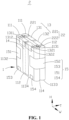
- FIG. 1 is a schematic structural view of an energy storage device in an implementation of the disclosure.
- the energy storage device 2 includes a jelly roll assembly 1 and a connector 22.
- the jelly roll assembly 1 includes at least one jelly roll 111.
- the jelly roll assembly 1 includes two jelly rolls 111.
- the jelly roll assembly 1 includes one or more jelly rolls 111.
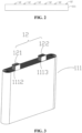
- each jelly roll 111 is formed by winding an electrode sheet 1111.
- the electrode sheet 1111 includes multiple tabs 12, and the multiple tabs 12 are arranged in a thickness direction of the tabs 12 after winding the electrode sheet 1111. Referring to FIG.
- the jelly roll 111 has a first side surface 112 and a first end surface 1131 connected with the first side surface 112.
- the multiple tabs 12 are bent at roots of the multiple tabs 12 and close to the first end surface 1131.
- the multiple tabs 12 have a connection surface 120 away from the first end surface 1131.
- the connector 22 is disposed on the connection surface 120 and connected with the multiple tabs 12.
- the jelly roll assembly 1 further includes a first insulation patch 13.
- the first insulation patch 13 adheres to and covers a surface of the connector 22 away from the connection surface 120 and is bent and extends to the first side surface 112. As illustrated by curve B in FIG.
- the soldering residues that fall off may cause short circuit.
- the soldering residues that fall off may be corroded by an electrolyte to form metal ions, where the metal ions may be precipitated on a surface of a negative electrode sheet of the electrode sheet 1111 along charging/discharging cycles, and gradually penetrate a separator between a positive electrode sheet and the negative electrode sheet of the electrode sheet 1111 to cause short circuit.
- the first insulation patch 13 since the first insulation patch 13 adheres to and covers the connector 22 and extends to the first side surface 112, the first insulation patch 13 may cover the connector 22 and the tab 12 to the maximum extent.
- the first insulation patch 13 may stick the soldering residues and prevent the soldering residues from entering the jelly roll 111, thus improving the security of the energy storage device 2. Furthermore, as illustrated by curve B in FIG. 5 , when the discharge capacity of the energy storage device 2 in which the first insulation patch 13 is attached is attenuated to 90% of the rated capacity of the energy storage device 2, the cycle number of the energy storage device 2 is equal to or larger than 500, and when the discharge capacity of the energy storage device 2 in which the first insulation patch 13 is attached is attenuated to 80% of the rated capacity, the cycle number of the energy storage device 2 is equal to or larger than 1200. In contrast, as illustrated by curve A in FIG.
- the tab 12 is a metal sheet that is flexible and bendable, and the tab 12 has two large surfaces opposite each other and two small side surfaces connected with the two large surfaces, where an area of each of the two small side surfaces is significantly less than an area of each of the two large surfaces.
- a thickness of the tab 12 refers to a distance between the two opposite large surfaces of the tab 12. Therefore, the thickness direction of the tabs 12 refers to a direction perpendicular to the large surfaces of the tabs 12.
- the second one of the tabs 12 is stacked on the first one of the tabs 12 in the thickness direction of the tabs 12, the third one of the tabs 12 is stacked on the second one of the tabs 122 in the thickness direction of the tabs 12, and so on.
- the multiple tabs 12 After the winding, in the case where the jelly roll 111 is not connected with the connector 22, the multiple tabs 12 extend out substantially perpendicularly from an end face of the jelly roll 111 that is close to the first end surface 1131. In the case where the multiple tabs 12 are connected with the connector 22, the multiple tabs 12 are bent at the roots of the multiple tabs 12 and close to the first end surface 1131. The roots of the multiple tabs 12 refer to positions where the multiple tabs 12 are connected with the electrode sheet 1111.
- the multiple tabs 12 are bent at the roots of the multiple tabs 12 and close to the first end surface 1131, which means that a plane where the multiple tabs 12 are located is parallel to a plane where the first end surface 1131 is located or that an included angle between the plane where the multiple tabs 12 are located and the plane where the first end surface 1131 is located is within a predetermined range.
- the included angle is less than or equal to 5 degrees, etc.
- An actual gap between the multiple tabs 12 and the first end surface 1131 may be minimal, and in some cases, the multiple tabs 12 may even be directly attached to the first end surface 1131, which is not limited herein.
- the first insulation patch 13 is a blue film adhesive.
- a main body of the blue film adhesive is made of polyethylene terephthalate (PET), and glue of the blue film adhesive is acrylic glue. It is appreciated that in other implementations, the first insulation patch 13 may be an insulating tape of other kinds and having a certain strength.
- a thickness of the first insulation patch 13 is 50 ⁇ m.
- the first insulation patch 13 has sufficient rigidity to prevent metal particles from penetrating the first insulation patch 13. It is appreciated that in other implementations, the thickness of the first insulation patch 13 may be, but is not limited to, 50 ⁇ m, for example, 45 ⁇ m or 55 ⁇ m, etc.
- a width direction W a height direction H
- the first insulation patch 13 covers at least an edge of the first side surface 112 connected with the first end surface 1131 in the height direction H.
- the electrode sheet 1111 includes a first electrode sheet 1112 and a second electrode sheet 1113.
- Each jelly roll 111 is formed by winding the first electrode sheet 1112 and the second electrode sheet 1113.
- the first electrode sheet 1112 includes multiple first tabs 121
- the second electrode sheet 1113 includes multiple second tabs 122
- the multiple first tabs 121 are arranged in a thickness direction of the first tabs 121 after the winding.
- the thickness direction of the first tabs 121 refers to a direction perpendicular to a large surface of the first tab 121.
- the multiple second tabs 122 are arranged in a thickness direction of the second tabs 122 after the winding.
- the thickness direction of the second tabs 122 refers to a direction perpendicular to a large surface of the second tab 122.
- a polarity of the multiple first tabs 121 is opposite to a polarity of the multiple second tabs 122.
- the multiple first tabs 121 may be positive tabs and the multiple second tabs 122 may be negative tabs. It can be understood that in other implementations, the multiple first tabs 121 may be negative tabs and the multiple second tabs 122 may be positive tabs.
- the connector 22 includes a first connector 221 and a second connector 222. Referring to FIG. 1 and FIG. 6 together.
- the multiple first tabs 121 have a first connection surface 1212 away from the first end surface 1131.
- the first connector 221 covers the first connection surface 1212 and is connected with the multiple first tabs 121.
- the multiple second tabs 122 have a second connection surface 1222 away from the first end surface 1131.
- the second connector 222 covers the second connection surface 1222 and is connected with the multiple second tabs 122.
- the first insulation patch 13 includes a first insulation sub-patch 131 and a second insulation sub-patch 132.
- the first insulation sub-patch 131 adheres to and covers a surface of the first connector 221 away from the first end surface 1131 and extends to the first side surface 112
- the second insulation sub-patch 132 adheres to and covers a surface of the second connector 222 away from the first end surface 1131 and extends to the first side surface 112.
- the first connector 221 is disposed on each of the multiple first tabs 121, and the first insulation sub-patch 131 is disposed on the first connector 221.
- the first insulation sub-patch 131 may extend from a position above the first end surface 1131, that is, the first insulation sub-patch 131 may extend from a surface of the first connector 221 away from the first end surface 1131 to the first side surface 112. In this way, a solder zone between the first tab 121 and the first connector 221 may be fully covered by the first insulation sub-patch 131, which prevents soldering residues in the solder zone, which may fall off in day-to-day use, from entering the jelly roll 111, thereby avoiding short circuit caused by the soldering residues.
- the soldering residues that fall off are prevented from being corroded to form metal ions by the electrolyte, where the metal ions may be precipitated on the surface of the negative electrode sheet of the electrode sheet 1111 along charging/discharging cycles and gradually penetrate the separator between the positive electrode sheet and the negative electrode sheet of the electrode sheet 1111 to cause short circuit.
- the second connector 222 is disposed on each of the multiple second tabs 122, and the second insulation sub-patch 132 is disposed on the second connector 222.
- the second insulation sub-patch 132 may extend from a position above the first end surface 1131, that is, the second insulation sub-patch 132 may extend from a surface of the second connector 222 away from the first end surface 1131 to the first side surface 112. In this way, a solder zone between the second tab 122 and the second connector 222 may be fully covered by the second insulation sub-patch 132. Thus, it is possible to avoid a problem that the service life of the energy storage device 2 is shortened due to short circuit that is caused by soldering residues that fall off, and the service life of the energy storage device 2 can be prolonged.
- the first insulation sub-patch 131 includes a first connection sub-portion 1311 and a second connection sub-portion 1312 connected with the first connection sub-portion 1311.
- the first connection sub-portion 1311 adheres to an upper side of the first end surface 1131, and the second connection sub-portion 1312 is bent downwards relative to the first connection sub-portion 1311 and adheres to the first side surface 112.
- the first connection sub-portion 1311 exceeds an edge of the first connector 221 by a distance greater than or equal to 2 mm.
- the first connection sub-portion 1311 exceeds an edge of the first connector 221 by a distance greater than or equal to 2 mm.
- a length of the second connection sub-portion 1312 is greater than or equal to 2 mm.
- the second insulation sub-patch 132 includes a third connection sub-portion 1321 and a fourth connection sub-portion 1322 connected with the third connection sub-portion 1321.
- the third connection sub-portion 1321 adheres to the upper side of the first end surface 1131.
- the fourth connection sub-portion 1322 is bent downwards relative to the third connection sub-portion 1321 and adheres to the first side surface 112.
- the third connection sub-portion 1321 exceeds an edge of the second connector 222 by a distance greater than or equal to 2 mm.
- the third connection sub-portion 1321 exceeds an edge of the second connector 222 by a distance greater than or equal to 2 mm.
- a length of the fourth connection sub-portion 1322 is greater than or equal to 2 mm.
- the first insulation sub-patch 131 has a reliable and stable connection with the jelly roll 111 and the first connector 221. Even if the jelly roll assembly 1 is soaked in the electrolyte for a long time, and even if any soldering residue falls off and sticks to a surface of the first insulation sub-patch 131, a connection reliability between the first insulation sub-patch 131 and the jelly roll 111 and the first connector 221 may not be affected.
- the second insulation sub-patch 132 has a reliable and stable connection with the jelly roll 111 and the second connector 222.
- the first insulation sub-patch 131 has an elongation at break of 120%-140% at a bending connection region between the first connection sub-portion 1311 and the second connection sub-portion 1312 when subject to an expansion force of the at least one jelly roll 111
- the second insulation sub-patch 132 has an elongation at break of 120%-140% at a bending connection region between the third connection sub-portion 1321 and the fourth connection sub-portion 1322 when subject to the expansion force of the at least one jelly roll 111.
- the elongation at break refers to a ratio of a displacement value at the point of breaking to an original length of a specimen, expressed as a percentage (%).
- the first insulation sub-patch 131 and the second insulation sub-patch 132 may also counteract the expansion force of the jelly roll 111 during charging and discharging.
- the first insulation sub-patch 131 and the second insulation sub-patch 132 may also serve to restrain an expansion of the jelly roll 111 during charging and discharging.
- a flatness of the jelly roll 111 can be maintained during charging and discharging, the electrolyte can have a better entry effect, and lithium plating can be reduced.
- a cycle number of charging and discharging of the energy storage device 2 can be increased, that is, the service life of the energy storage device 2 can be prolonged.
- the first insulation sub-patch 131 has a deformation ratio of 0-20% at the bending connection region between the first connection sub-portion 1311 and the second connection sub-portion 1312 when subject to the expansion force of the at least one jelly roll 111
- the second insulation sub-patch 132 has a deformation ratio of 0-20% at the bending connection region between the third connection sub-portion 1321 and the fourth connection sub-portion 1322 when subject to the expansion force of the at least one jelly roll 111.
- the deformation rate of the first insulation sub-patch 131 and the deformation rate of the second insulation sub-patch 132 can be controlled within a range of 0-20% to prevent fractures of the first insulation sub-patch 131 and the second insulation sub-patch 132 caused by the expansion force of the jelly roll 111.
- the first insulation sub-patch 131 and the second insulation sub-patch 132 may also be prevented from being excessively stretched, where excessive stretching of the first insulation sub-patch 131 and the second insulation sub-patch 132 may cause local thinning and reduced insulation performance of the first insulation sub-patch 131 and the second insulation sub-patch 132, which may adversely affect the cycling performance of the energy storage device 2.
- the jelly roll assembly 1 includes two first tabs 121 and two second tabs 122.
- the two first tabs 121 face each other, and the two second tabs 122 face each other.
- Each first tab 121 has a corresponding first insulation sub-patch 131, and each second tab 122 has a corresponding second insulation sub-patch 132. Therefore, soldering residues generated by each of the first tabs 121 and each of the second tabs 122 can be effectively controlled.
- a projection of the first connector 221 on the first end surface 1131 at least partially overlaps a projection of the first tab 121 on the first end surface 1131.
- the first connector 221 is disposed on a surface of the first tab 121 away from the first end surface 1131.
- the first insulation sub-patch 131 covers the first connector 221 and part of the first tab 121 that is not covered by the first connector 221. It can be understood that, the first insulation sub-patch 131 fully covers at least a soldering connection zone between the first connector 221 and the first tab 121.
- a projection of the second connector 222 on the first end surface 1131 at least partially overlaps a projection of the second tab 122 on the first end surface 1131.
- the second connector 222 is disposed on a surface of the second tab 122 away from the first end surface 1131.
- the second insulation sub-patch 132 covers the second connector 222 and part of the second tab 122 that is not covered by the second connector 222. It can be understood that, the second insulation sub-patch 132 fully covers at least a soldering connection zone between the second connector 222 and the second tab 122.
- the first insulation sub-patch 131 can effectively prevent soldering residues on the soldering connection zone between the first tab 121 and the first connector 221 from falling off
- the second insulation sub-patch 132 can effectively prevent soldering residues on the soldering connection zone of the second tab 122 and the second connector 222 from falling off.
- the jelly roll 111 further has a second side surface 114 opposite the first side surface 112.
- the second side surface 114 of the two jelly rolls 111 abut against each other.
- the tab 12 has an attachment surface 124 close to the first end surface 1131.
- the jelly roll assembly 1 further includes a second insulation patch 16. The second insulation patch 16 adheres to and covers the attachment surface 124 and extends to the first end surface 1131 and the second side surface 114.
- the second insulation patch 16 adheres to and covers the attachment surface 124 and extends to the first end surface 1131 and the second side surface 114 of the jelly roll 111, which can ensure that the attachment surface 124 of the tab 12 may be fully covered, preventing any soldering residue or impurities on the attachment surface 124 of the tab 12 from falling off. Furthermore, the second insulation patch 16 also extends to the first end surface 1131 and the second side surface 114 of the jelly roll 111, so that connection reliability among the second insulation patch 16, the tab 12, the first end surface 1131, and the second side surface 114 can be significantly increased, and no part may fall off even if the jelly roll 111 is soaked in the electrolyte for a long time.
- the second insulation patch 16 is a blue film adhesive.
- a main body of the blue film adhesive is made of PET, and glue of the blue film adhesive is acrylic glue. It is appreciated that in other implementations, the second insulation patch 16 may be an insulating tape of other kinds and having a certain strength.
- the thickness of the second insulation patch 16 is 50 ⁇ m.
- the second insulation patch 16 may have a sufficient thickness to prevent metal particles from penetrating the second insulation patch 16. It is appreciated that in other implementations, the thickness of the second insulation patch 16 may be, but is not limited to, 50 ⁇ m, for example, 45 ⁇ m or 55 ⁇ m, etc.
- the multiple first tabs 121 have a first attachment surface 1211 close to the first end surface 1131.
- the multiple second tabs 122 have a second attachment surface 1221 close to the first end surface 1131.
- the second insulation patch 16 includes a third insulation sub-patch 161 and a fourth insulation sub-patch 162.
- the third insulation sub-patch 161 adheres to and covers the first attachment surface 1211 and extends to the first end surface 1131 and the second side surface 114 of the jelly roll 111.
- the fourth insulation sub-patch 162 adheres to and covers the second attachment surface 1221 and extends to the first attachment surface 1131 and the second side surface 114.
- the first attachment surface 1211 of the first tabs 121 is covered by the third insulation sub-patch 161, so that the first attachment surface 1211 of the first tab 121 can be effectively protected, preventing soldering residues on the first tab 121 from falling off to a maximum extent.
- the third insulation sub-patch 161 may further extend to the first end surface 1131 and the second side surface 114, so that connection reliability among the third insulation sub-patch 161, the first tab 121, the first end surface 1131, and the second side surface 114 of the jelly roll 111 can be significantly increased, and no part may fall off even if the jelly roll 111 is soaked in the electrolyte for a long time, thereby increasing the connection reliability.
- the second attachment surface 1221 of the second tabs 122 is covered by the fourth insulation sub-patch 162, so that the second attachment surface 1221 of the second tab 122 can be effectively protected, preventing soldering residues on the second tab 122 from falling off to a maximum extent.
- the fourth insulation sub-patch 162 also extends to the first end surface 1131 and the second side surface 114, so that the connection reliability among the fourth insulation sub-patch 162, the second tab 122, the first end surface 1131, and the second side surface 114 can be significantly increased, and no part may fall off even if the jelly roll 111 is soaked in the electrolyte for a long time, thereby increasing the connection reliability.
- the third insulation sub-patch 161 exceeds an edge of the first attachment surface 1211 by a distance greater than or equal to 2 mm.
- the third insulation sub-patch 161 exceeds an edge of the first attachment surface 1211 by a distance greater than or equal to 2 mm.
- the fourth insulation sub-patch 162 exceeds an edge of the second attachment surface 1221 by a distance greater than or equal to 2 mm.
- the fourth insulation sub-patch 162 exceeds an edge of the second attachment surface 1221 by a distance greater than or equal to 2 mm.
- the third insulation sub-patch 161 extends on the second side surface 114 by a distance greater than or equal to 2 mm.
- the fourth insulation sub-patch 162 extends on the second side surface 114 by a distance greater than or equal to 2 mm.
- the third insulation sub-patch 161 has a reliable and stable connection with the jelly roll 111. Even if the jelly roll assembly 1 is soaked in the electrolyte for a long time, and even if any soldering residue falls off and sticks to a surface of the third insulation sub-patch 161, a connection reliability between the third insulation sub-patch 161 and the jelly roll 111 may not be affected.
- the fourth insulation sub-patch 162 has a reliable and stable connection with the jelly roll 111.
- the third insulation sub-patch 161 has an elongation at break of 120-140% at a bending connection region between the first end surface 1131 and the second side surface 114 when subject to the expansion force of the jelly roll 111.
- the fourth insulation sub-patch 162 has an elongation at break of 120-140% at a bending connection region between the first end surface 1131 and the second side 114 when subject to the expansion force of the jelly roll 111.
- the third insulation sub-patch 161 and the fourth insulation sub-patch 162 may also counteract the expansion force of the jelly roll 111 during charging and discharging.
- the third insulation sub-patch 161 and the fourth insulation sub-patch 162 may also serve to restrain the expansion of the jelly roll 111 during charging and discharging.
- the flatness of the jelly roll 111 can be maintained during charging and discharging, the electrolyte can have a better entry effect, and lithium plating can be reduced,
- the cycle number of charging and discharging of the energy storage device 2 can be increased, that is, the service life of the energy storage device 2 can be prolonged.
- the first insulation sub-patch 131 and the second insulation sub-patch 132 may counteract an expansion force of the jelly roll 111 that is applied on the first side surface 112 during charging and discharging.
- the third insulation sub-patch 161 and the fourth insulation sub-patch 162 may also counteract an expansion force of the jelly roll 111 that is applied on the second side surface 114 during charging and discharging.
- a balance in bundling protection forces applied on the jelly roll 111 in the thickness direction T of the jelly roll 111 can be realized during charging and discharging, further improving the entry effect of the electrolyte and reducing lithium plating.
- the cycle number of charging and discharging of the energy storage device 2 can be further increased, that is, the service life of the energy storage device 2 can be further prolonged.
- the first connector 221 includes a first connection region 2210 and a second connection region 2211. In the implementations, there are two first connection regions 2210 and one second connection region 2211. A U-shaped structure is formed between one second connection region 2211 and two first connection regions 2210. Each first connection region 2210 is connected with one first tab 121. The first insulation sub-patch 131 covers one side of the first connection region 2210 away from the first end surface 1131 and the second connection region 2211 is exposed.
- the second connector 222 includes a third connection region 2220 and a fourth connection region 2221. In the implementations, there are two third connection regions 2220 and one fourth connection region 2221. A U-shaped structure is formed between one fourth connection region 2221 and two third connection regions 2220. Each third connection region 2220 is connected with one second tab 122. The second insulation sub-patch 132 covers one side of the third connection region 2220 away from the first end surface 1131 and the fourth connection region 2221 is exposed.
- the second connection region 2211 is configured to be connected with a first pole
- the fourth connection region 2221 is configured to be connected with a second pole. Since the first insulation sub-patch 131 covers the one side of the first connection region 2210 away from the first end surface 1131 and the second connection region 2211 is exposed, it is convenient for the second connection region 2211 to be soldered to the first pole. Since the second insulation sub-patch 132 covers the one side of the third connection region 2220 away from the first end surface 1131 and the fourth connection region 2221 is exposed, it is convenient for the fourth connection region 2221 to be soldered with the second pole.
- the jelly roll assembly 1 further includes a third insulation patch 171 and a fourth insulation patch 172.
- the third insulation patch 171 covers one side of the second connection region 2211 facing the first end surface 1131.
- the fourth insulation patch 172 covers one side of the fourth connection region 2221 facing the first end surface 1131.
- the third insulation patch 171 can prevent soldering residues generated during a soldering of the first pole from falling off
- the fourth insulation patch 172 can prevent soldering residues generated during a soldering of the second pole from falling off.
- soldering residues generated during soldering of the first pole and the second pole can be prevented from falling into the jelly roll 111, where soldering residues may cause problems such as short circuit, thereby affecting the service life of the energy storage device 2.
- the third insulation patch 171 fully covers one side of the first connector 221 facing the first end surface 1131
- the fourth insulation patch 172 fully covers one side of the second connector 222 facing the first end surface 1131.
- the third insulation patch 171 can sufficiently protect the second connection region 2211, an adhesive strength between the third insulation patch 171 and the second connection region 2211 can be enhanced. Even if the third insulation patch 171 is soaked in the electrolyte for a long time, the third insulation patch 171 may not be separated from the second connection region 2211, thereby improving the connection stability.
- the fourth insulation patch 172 can sufficiently protect the fourth connection region 2221, an adhesive strength between the fourth insulation patch 172 and the fourth connection region 2221 can be enhanced, thereby improving the adhesive stability. Even if the fourth insulation patch 172 is soaked in the electrolyte for a long time, the fourth insulation patch 172 may not be separated from the fourth connection region 2221.
- the third insulation patch 171 exceeds an edge of the second connection region 2211 by a distance greater than or equal to 2 mm, and in the width direction W, the third insulation patch 171 exceeds an edge of the second connection region 2211 by a distance greater than or equal to 2 mm.
- the fourth insulation patch 172 exceeds an edge of the fourth connection region 2221 by a distance greater than or equal to 2 mm, and in the width direction W, the fourth insulation patch 172 exceeds an edge of the fourth connection region 2221 by a distance greater than or equal to 2 mm.
- the adhesive strength of the third insulation patch 171 is further enhanced, and even if the third insulation patch 171 is soaked in the electrolyte for a long time, the third insulation patch 171 may not be separated from the second connection region 2211, thereby improving the connection stability.
- the adhesive strength of the fourth insulation patch 172 is further enhanced, the adhesive stability is improved, and even if the fourth insulation patch 172 is soaked in the electrolyte for a long time, the fourth insulation patch 172 may not be separated from the fourth connection region 2221.
- the third insulation patch 171 extends from the second connection region 2211 to cover the first connection region 2210 and partially overlaps the third insulation sub-patch 161.
- the fourth insulation patch 172 extends from the fourth connection region 2221 to cover the third connection region 2220 and partially overlaps the fourth insulation sub-patch 162.
- the third insulation patch 171 can sufficiently protect the second connection region 2211, and the third insulation patch 171 partially overlaps and adheres to the third insulation sub-patch 161.
- the connection reliability of the third insulation patch 171 and the connection reliability of the third insulation sub-patch 161 can be enhanced. Even if the jelly roll 111 is soaked in the electrolyte for a long time, the third insulation patch 171 may not be separated from the second connection region 2211, and the third insulation sub-patch 161 may not be separated from the first connection region 2210, and the third insulation patch 171 and the third insulation sub-patch 161 may be not separated from each other, thereby improving the connection stability.
- the fourth insulation patch 172 may sufficiently protect the fourth connection region 2221, and the third connection region 2220 may partially overlap and adhere to the fourth insulation sub-patch 162.
- the connection reliability of the fourth insulation patch 172 and the connection reliability of the fourth insulation sub-patch 162 can be enhanced. Even if the jelly roll 111 is soaked in the electrolyte for a long time, the fourth insulation patch 172 may not be separated from the fourth connection region 2221, the fourth insulation sub-patch 162 may not be separated from the third connection region 2220, and the fourth insulation patch 172 may be not separated from the fourth insulation sub-patch 162.
- the jelly roll 111 is provided with a tail portion 1110 on the first side surface 112, the jelly roll assembly 1 further includes a tail insulation patch 14, and the tail insulation patch 14 adheres to and covers the first side surface 112 and the tail portion 1110.
- the electrode sheet 1111 includes the first electrode sheet 1112 and the second electrode sheet 1113.
- the jelly roll 111 is formed by winding the first electrode sheet 1112 and the second electrode sheet 1113.
- the jelly roll 111 has the tail portion 1110 wound.
- the jelly roll assembly 1 includes two jelly rolls 111 arranged back to back, the two jelly rolls 111 serve as the two opposite outer jelly rolls.
- the jelly roll assembly 1 includes multiple jelly rolls 111 arranged back-to-back, for example that the jelly roll assembly 1 includes four jelly rolls 111, the tail portions of two inner jelly rolls 111 are pressed by the two adjacent jelly rolls 111, and the two outermost jelly rolls 111 of the four jelly rolls 111 are two opposite outer jelly rolls.
- the tail insulation patch 14 adheres to the first side surface 112 and covers the tail portion 1110 of the outer jelly roll, and can counteract a tension force applied on the tail portion 1110 caused by the expansion of the jelly roll 111 during charging and discharging.
- the tail insulation patch 14 is a blue film adhesive.
- a main body of the blue film adhesive is made of PET, and glue of the blue film adhesive is acrylic glue. It is appreciated that in other implementations, the tail insulation patch 14 may be an insulating tape of other kinds and having a certain strength.
- the thickness of the tail insulation patch 14 is 30 ⁇ m. It can be understood that in other implementations, the thickness of the tail insulation patch 14 may be, but is not limited to, 30 ⁇ m.
- the tail insulation patch 14 has a width ranging from 24 mm to 26 mm.
- a difference between a size of the tail insulation patch 14 of the jelly roll 111 and a size of the jelly roll 111 is less than a preset threshold.
- the tail insulation patch 14 can substantially cover the first side surface 112 of the jelly roll 111 in the height direction H of the jelly roll 111, so as to cover the tail portion 1110 of the jelly roll 111, thereby counteracting a tension force applied on the tail portion 1110 caused by the expansion of the jelly roll 111 during charging and discharging and maintaining the structural stability.
- the tail insulation patch 14 is positioned between the first insulation sub-patch 131 and the second insulation sub-patch 132.
- the tail insulation patch 14, the first insulation sub-patch 131, and the second insulation sub-patch 132 respectively cover different regions of the first side surface, and thus provide corresponding adhesive forces for different regions to counteract the expansion force of the at least one jelly roll 111 during charging and discharging.
- the tail insulation patch 14 at least partially covers and adheres to at least one of the first insulation sub-patch 131 or the second insulation sub-patch 132. In the implementations, at least one of the first insulation sub-patch 131 or the second insulation sub-patch 132 partially overlaps the tail insulation patch 14.
- At least one of the first insulation sub-patch 131 or the second insulation sub-patch 132 partially overlaps the tail insulation patch 14 to further enhance adhesion, thereby increasing the adhesion stability between the first insulation sub-patch 131 and the tail insulation patch 14 and the adhesion stability between the second insulation sub-patch 132 and the tail insulation patch 14. Even if the at least one jelly roll 111 is soaked in the electrolyte for a long time in practical use, the first insulation sub-patch 131 and the second insulation sub-patch 132 may not be separated from the at least one jelly roll 111 or upwarp, thereby significantly improving the use stability of the energy storage device 2.
- the jelly roll 111 further includes a third side surface 1132, a fourth side surface 1133, and a second end surface 1134.
- the second end surface 1134 is opposite to the first end surface 1131.
- the third side surface 1132 is opposite to the fourth side surface 1133.
- the first end surface 1131 is connected with one side of the first side surface 112, one side of the second side surface 114, one side of the third side surface 1132, and one side of the fourth side surface 1133.
- the second end face 1134 is connected with the other side of the first side surface 112, the other side of the second side surface 114, the other side of the third side surface 1132, and the other side of the fourth side surface 1133.
- the jelly roll assembly 1 further includes bundling insulation patches 15 disposed on the third side surface 1132, the fourth side surface 1133, and the second end surface 1134. Two ends of each of the bundling insulation patches 15 respectively extend to two first side surfaces 112.
- the first side surface 112 and the second side surface 114 each have a larger surface area than each of a surface area of the third side surface 1132, a surface area of the fourth side surface 1133, a surface area of the first end surface 1131, and a surface area of the second end surface 1134.
- the two ends of each of the bundling insulation patches 15 respectively extend to the other one of the first side surface 112 or second side surface 114 of the at least one jelly roll 111. As illustrated by curve C in FIG.
- the cycle number of the energy storage device 2 is equal to or larger than 900, and when the discharge capacity of the energy storage device 2 in which the bundling insulation patches 15 and the first insulation patch 13 are attached is attenuated to 80% of the rated capacity, the cycle number of the energy storage device 2 is equal to or larger than 1500.
- the electrode sheet 1111 of the energy storage device 2 may expand during charging and discharging, wrinkles may appear, and impregnation of the electrolyte at the wrinkles is difficult, which easily results in lithium plating and reduces the cycle number.
- the expansion of the electrode sheet 1111 can be effectively restrained by the bundling insulation patches 15, so that the electrode sheet 1111 can maintain a good fitting interface, thereby prolonging the service life. Specifically, referring to FIG. 5 .
- the cycle number of the energy storage device 2 is equal to or larger than 900, and when the discharge capacity of the energy storage device 2 in which the bundling insulation patches 15 are attached is attenuated to 80% of the rated capacity, the cycle number of the energy storage device 2 is equal to or less than 1500. As illustrated by curve C in FIG.
- the cycle number of the energy storage device 2 is equal to or larger than 900, and when the discharge capacity of the energy storage device 2 in which both the bundling insulation patches 15 and the first insulation patch 13 are attached is attenuated to 80% of the rated capacity, the cycle number of the energy storage device 2 is equal to or larger than 1500.
- the bundling insulation patch 15 is a blue film adhesive.
- a main body of the blue film adhesive is made of PET, and glue of the blue film adhesive is acrylic glue. It is be appreciated that in other implementations, the bundling insulation patch 15 may be an insulating tape of other kinds and having a certain strength.
- the thickness of the bundling insulation patch 15 is 30 ⁇ m. It can be understood that in other implementations, the thickness of the bundling insulation patch 15 may be, but is not limited to, 30 ⁇ m.
- the bundling insulation patch 15 has a width ranging from 24 mm to 26 mm.
- the bundling insulation patch 15 extends on the exposed first side surface 112 and/or the exposed second side surface 114 of the at least one jelly roll 111 by a distance of greater than or equal to 10 mm and less than or equal to 30 mm.
- the bundling insulation patches 15 are disposed on the third side surface 1132, the fourth side surface 1133, and the second end surface 1134.
- the bundling insulation patch 15 can provide a pre-tightening force for the at least two jelly rolls 111, so that the at least one jelly roll 111 may not shake or move at the third side surface 1132, the fourth side surface 1133, and/or the second end surface 1134, which can effectively restrict the expansion of the electrode sheet 1111, maintain a good fitting interface of the electrode sheet 1111, and prolong the service life.
- the first tab 121 and the second tab 122 are respectively disposed on the first end surface 1131 and the second end surface 1134, and in this case, the bundling insulation patch 15 is disposed on the third side surface 1132 and the fourth side surface 1133.
- the bundling insulation patch 15 may provide a pre-tightening force for the at least two jelly rolls 111, so that the at least one jelly roll 111 may not shake or move at the third side surface 1132 and the fourth side surface 1133, which can effectively restrict the expansion of the electrode sheet 1111, maintain a good fitting interface of the electrode sheet 1111, and prolong the service life.
- an end cover at a corresponding position can provide a pre-tightening force and a corresponding supporting force, thereby avoiding shaking or movement.
- the number of the bundling insulation patches 15 attached to each of the third side surface 1132, the fourth side surface 1133, and the second end surface 1134 is directly proportional to the length of the corresponding side surface.
- the number of the bundling insulation patches 15 disposed on the third side surface 1132 is directly proportional to the length of the fourth side surface 1133
- the number of the bundling insulation patches 15 disposed on the fourth side surface 1133 is directly proportional to the length of the fourth side surface 1133
- the number of the bundling insulation patches 15 disposed on the second end surface 1134 is directly proportional to the length of the second end surface 1134.
- the second end surface 1134 has a relatively large size in the width direction W
- a relatively large number of the bundling insulation patches 15 are disposed on the second end surface 1134.
- the third side surface 1132 and the fourth side surface 1133 have a relatively small size in the height direction H, a relatively small number of the bundling insulation patches 15 are disposed on the third side surface 1132 and the fourth side surface 1133.
- a length of the second end surface 1134 is greater than a length of the third side surface 1132 and a length of the fourth side surface 1133.
- At least two bundling insulation patches 15 are arranged at intervals on the second end surface 1134.
- At least one bundling insulation patch 15 is disposed at intervals on the fourth side surface 1133, for example, one bundling insulation patch 15 is centrally disposed on the fourth side surface 1133.
- the second end surface 1134 has a relatively large size in the width direction W, thus at least two bundling insulation patches 15 are disposed on the second end surface 1134.
- the third side surface 1132 and the fourth side surface 1133 have a relatively small size in the height direction H, thus at least one bundling insulation patch 15 is disposed on each of the third side surface 1132 and the fourth side surface 1133. In this way, a balance in adhesive forces of different regions of the jelly roll 111 can be achieved.
- the at least one jelly roll 111 includes two jelly rolls 111.
- the two jelly rolls 111 abut against each other at two second side surfaces 114.
- the bundling insulation patches 15 include a first bundling insulation patch 151, a second bundling insulation patch 152, a third bundling insulation patch 153, and a fourth bundling insulation patch 154.
- the first bundling insulation patch 151 is disposed on the third side surface 1132 and has two ends respectively extending from the third side surface 1132 to two first side surfaces 112 that are exposed.
- the second bundling insulation patch 152 is disposed on the fourth side surface 1133 and has two ends respectively extending from the fourth side surface 1133 to the two first side surfaces 112 that are exposed.
- the third bundling insulation patch 153 and the fourth bundling insulation patch 154 are disposed on the second end surface 1134 at an interval. Furthermore, the third bundling insulation patch 153 has two ends respectively extending from the second end surface 1134 to the two first side surfaces 112 that are exposed.
- the fourth bundling insulation patch 154 has two ends respectively extending from the second end surface 1134 to the two first side surfaces 112 that are exposed.
- the first bundling insulation patch 151 and the second bundling insulation patch 152 are symmetrically arranged about a central line of the jelly roll 111.
- the third bundling insulation patch 153 and the fourth bundling insulation patch 154 are symmetrically arranged about the central line of the jelly roll 111.
- the first bundling insulation patch 151 and the second bundling insulation patch 152 respectively extend on two exposed first side surfaces 112 by a distance of greater than or equal to 10 mm and less than or equal to 30 mm.
- the third bundling insulation patch 153 and the fourth bundling insulation patch 154 respectively extend on two exposed first side surfaces 112 by a distance of greater than or equal to 10 mm and less than or equal to 30 mm.
- the first bundling insulation patch 151 is disposed on the third side surface 1132 of the jelly roll 111
- the second bundling insulation patch 152 is disposed on the fourth side surface 1133 of the jelly roll 111
- the third bundling insulation patch 153 and the fourth bundling insulation patch 154 are disposed on the second end surface 1134 of the jelly roll 111, so that a more secure and balanced bundling can be achieved, thereby effectively restraining the expansion of the electrode sheet 1111, maintaining a good fitting interface, and prolonging the service life.
- the third bundling insulation patch 153 is closer to the third side surface 1132 than the first insulation sub-patch 131, and the fourth bundling insulation patch 154 is closer to the fourth side surface 1133 than the second insulation sub-patch 132.
- the first insulation sub-patch 131 and the second insulation sub-patch 132 are closed to the center, and the third bundling insulation patch 153 and the fourth bundling insulation patch 154 are relatively closer to the fourth side surface 1133 and the third side surfaces 1132 opposite the fourth side surface 1133, it can prevent the jelly roll 111 from expanding or shaking at positions close to the fourth side surface 1133 and the third side surface 1132, so that the overall structure is more stable.
- a ratio of a tensile force that the bundling insulation patches 15 are able to withstand to an adhering area of the bundling insulation patches 15 on the at least one jelly roll 111 is greater than an expansion-force pressure of the at least one jelly roll 111, where the expansion-force pressure of the at least one jelly roll 111 is less than or equal to 0.4 MPa.
- the ratio of the tensile force that the bundling insulation patches 15 are able to withstand to the adhering area of the bundling insulation patches 15 on the at least one jelly roll 111 is greater than the expansion-force pressure of the at least one jelly roll 111, where the expansion-force pressure of the at least one jelly roll 111 is less than or equal to 0.4 MPa.
- the bundling insulation patches 15 apply a pre-tightening force to restrain the expansion, so that an adhesion between the separator and the negative electrode sheet is better, which can prevent the separator and the negative electrode sheet from moving apart and forming wrinkles as a result of the expansion, thereby improving the entry effect of the electrolyte, reducing lithium plating, and prolonging the service life.
- the energy storage device 2 further includes a casing 21 and a cover plate 23.
- the casing 21 defines an opening 211 at one side of the casing 21, the jelly roll assembly 1 is received in the casing 21, and the connector 22 is disposed on one side of the cover plate 23 facing the casing 21.
- the cover plate 23 covers the opening 211 of the casing 21 to define an accommodating space, and the jelly roll assembly 1 and the connector 22 are accommodated in the accommodating space.
- the casing 21 is one of an aluminum housing, a steel housing, a stainless steel housing, etc.
- the energy storage device 2 is one of a lithium iron phosphate battery, a pear acid battery, a lithium battery, etc.
- the energy storage device 2 is a square-casing battery.
- the energy storage device 2 may be, but is not limited to, a battery cell, a battery module, a battery pack, etc.
- the electric device includes the above-identified energy storage device 2, where the energy storage device 2 is configured for providing electric energy.
Landscapes
- Chemical & Material Sciences (AREA)
- Chemical Kinetics & Catalysis (AREA)
- Electrochemistry (AREA)
- General Chemical & Material Sciences (AREA)
- Engineering & Computer Science (AREA)
- Manufacturing & Machinery (AREA)
- Connection Of Batteries Or Terminals (AREA)
- Secondary Cells (AREA)
Abstract
Description
- This disclosure relates to the field of energy storage, and in particular to an energy storage device and an electronic device.
- In the process of producing a lithium battery, a positive electrode sheet, a separator and a negative electrode sheet need to be stacked and wound to form a jelly roll, and then two or more jelly rolls are connected in series or in parallel to obtain a battery. After the jelly roll is wound, tabs of the jelly roll need to be soldered. However, after tab soldering of the existing jelly roll, soldering residues are easy to fall into the jelly roll to cause internal short circuit, which may pose risks during use, and shorten the battery life.
- In a first aspect, an energy storage device is provided. The energy storage device includes a jelly roll assembly and a connector. The jelly roll assembly includes at least one jelly roll. Each of the at least one jelly roll is formed by winding an electrode sheet. The electrode sheet includes multiple tabs. The multiple tabs are arranged in a thickness direction of the tabs after winding the electrode sheet. After the winding, the jelly roll has a first side surface and a first end surface connected with the first side surface, the multiple tabs are bent at roots of the multiple tabs and attached to the first end surface. The multiple tabs have a connection surface away from the first end surface. The connector is disposed on the connection surface and connected with the multiple tabs. The jelly roll assembly further includes a first insulation patch. The first insulation patch adheres to and covers a surface of the connector away from the first end surface, and is bent and extends to the first side surface. Under full charge/full discharge cycle at 1 current (C) and 25 °C, when a discharge capacity of the energy storage device in which the first insulation patch is attached is attenuated to 90% of a rated capacity of the energy storage device, a cycle number of the energy storage device is equal to or larger than 500, and when the discharge capacity of the energy storage device is attenuated to 80% of the rated capacity, the cycle number of the energy storage device is equal to or larger than 1200.
- In a second aspect, an electric device is further provided in the disclosure. The electric device includes the energy storage device in the first aspect, and the energy storage device is configured for providing electric energy.
- In order to describe technical solutions of implementations of the disclosure more clearly, the following will give a brief introduction to accompanying drawings used for describing the implementations. Obviously, the accompanying drawings hereinafter described are some implementations of the disclosure. Based on these drawings, those of ordinary skill in the art can also obtain other drawings without creative effort.
-
FIG. 1 is a schematic structural view of an energy storage device in an implementation of the disclosure. -
FIG. 2 is a schematic structural view of an unwound electrode sheet in an implementation of the disclosure. -
FIG. 3 is a schematic perspective structural view illustrating a first electrode sheet and a second electrode sheet that are stacked and wound in an implementation of the disclosure. -
FIG. 4 is a schematic structural view illustrating positions of a tab, a first insulation patch, a second insulation patch, and a connector of a jelly roll in an implementation of the disclosure. -
FIG. 5 is a graph illustrating a relationship between capacity fade and cycle numbers of an energy storage device under full charge/full discharge cycle at 1 current (C) and 25 °C in an implementation of the disclosure. -
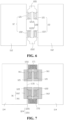
FIG. 6 is a schematic plan view of two jelly rolls in the energy storage device ofFIG. 1 in an implementation of the disclosure, where the two jelly rolls are unfolded relative to each other with their respective tabs as reference, and a connector, a first insulation patch, a tail insulation patch, and bundling insulation patches of the energy storage device ofFIG. 1 are omitted. -
FIG. 7 is a schematic plan view of the two jelly rolls inFIG. 6 in an implementation of the disclosure, a viewing direction inFIG. 7 and a viewing direction inFIG. 6 form 180 degrees. -
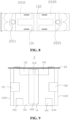
FIG. 8 is a top view of the energy storage device inFIG. 1 in an implementation of the disclosure, where a cover plate of the energy storage device is illustrated. -
FIG. 9 is a front view of the energy storage device inFIG. 1 in an implementation of the disclosure, where a cover plate of the energy storage device is illustrated. -
FIG. 10 is a left view of the energy storage device inFIG. 9 in an implementation of the disclosure. -
FIG. 11 is a bottom view of the energy storage device inFIG. 9 in an implementation of the disclosure. -
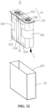
FIG. 12 is a schematic exploded view of an energy storage device in an implementation of the disclosure. -
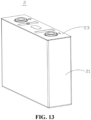
FIG. 13 is an assembly view of the energy storage device inFIG. 12 in an implementation of the disclosure. - Reference signs:
jelly roll assembly 1;jelly roll 111;first side surface 112;second side surface 114;first end surface 1131;third side surface 1132;fourth side surface 1133;second end surface 1134;tab 12;connection surface 120;attachment surface 124;first connection surface 1212;second connection surface 1222;first attachment surface 1211;second attachment surface 1221;first insulation patch 13;first insulation sub-patch 131;first connection sub-portion 1311; second connection sub-portion 1312;second insulation sub-patch 132;third connection sub-portion 1321;fourth connection sub-portion 1322;second insulation patch 16;third insulation sub-patch 161;fourth insulation sub-patch 162;third insulation patch 171;fourth insulation patch 172;electrode sheet 1111;first electrode sheet 1112;second electrode sheet 1113;first tab 121;second tab 122;tail portion 1110;tail insulation patch 14;bundling insulation patch 15; firstbundling insulation patch 151; secondbundling insulation patch 152; thirdbundling insulation patch 153; fourthbundling insulation patch 154;casing 21; opening 211;connector 22;first connector 221;first connection region 2210;second connection region 2211;second connector 222;third connection region 2220;fourth connection region 2221;cover plate 23;energy storage device 2. - The technical solutions in implementations of the disclosure are clearly and completely described hereinafter with reference to the accompanying drawings in the implementations of the disclosure. Apparently, the described implementations are merely part of rather than all of the implementations of the disclosure. All other implementations obtained by those of ordinary skill in the art based on the implementations provided herein without creative efforts shall fall within the scope of the disclosure.
- Unless otherwise defined, all technical and scientific terms used herein have the same meaning as commonly understood by those of ordinary skill in the art of the disclosure. The terms used herein are for the purpose of describing implementations only and are not intended to limit the disclosure.
- The terms "first", "second", and the like used in the specification, claims, and accompany drawings of the disclosure are used for distinguishing different objects rather than for describing a particular sequence. The terms "one", "a", "the", and the like used in the disclosure are not intended to limit a quantity, but are merely intended to indicate that at least one exists. The terms "include", "comprise", "contain", and the like are intended to mean that elements or objects preceding the term encompass elements, objects, or the equivalents listed after the term, without excluding other elements or objects. The terms "connect", "couple", or the like are not limited to physical or mechanical connections but may include electrical connections, whether direct or indirect. The term "cover" refers to a direct contact between two components without a third-party component, or an indirect contact between two components via a third-party components between the two components.
- The terms "an implementation", "a specific implementation", "an example", and the like described herein mean that a particular feature, structure, material, or characteristic described in conjunction with the implementations or examples may be contained in at least one implementation or example of the disclosure. The exemplary expressions of the above terms in the specification do not necessarily refer to the same implementation or example. Furthermore, the particular feature, structure, material, or characteristic described may be combined in any suitable manner in one or more implementations or examples.
- Referring to
FIG. 1, FIG. 1 is a schematic structural view of an energy storage device in an implementation of the disclosure. Theenergy storage device 2 includes ajelly roll assembly 1 and aconnector 22. Thejelly roll assembly 1 includes at least onejelly roll 111. In the implementations, thejelly roll assembly 1 includes twojelly rolls 111. In other examples, thejelly roll assembly 1 includes one ormore jelly rolls 111. Referring toFIGs. 2 and 3 , eachjelly roll 111 is formed by winding anelectrode sheet 1111. Theelectrode sheet 1111 includesmultiple tabs 12, and themultiple tabs 12 are arranged in a thickness direction of thetabs 12 after winding theelectrode sheet 1111. Referring toFIG. 1 again, after the winding, thejelly roll 111 has afirst side surface 112 and afirst end surface 1131 connected with thefirst side surface 112. Referring toFIGs. 3 and4 , themultiple tabs 12 are bent at roots of themultiple tabs 12 and close to thefirst end surface 1131. Themultiple tabs 12 have aconnection surface 120 away from thefirst end surface 1131. Theconnector 22 is disposed on theconnection surface 120 and connected with themultiple tabs 12. Thejelly roll assembly 1 further includes afirst insulation patch 13. Thefirst insulation patch 13 adheres to and covers a surface of theconnector 22 away from theconnection surface 120 and is bent and extends to thefirst side surface 112. As illustrated by curve B inFIG. 5 , under full charge/full discharge cycle at 1 current (C) and 25 °C, when a discharge capacity of theenergy storage device 2 in which thefirst insulation patch 13 is attached is attenuated to 90% of a rated capacity of theenergy storage device 2, a cycle number of theenergy storage device 2 is equal to or larger than 500, and when the discharge capacity of theenergy storage device 2 in which thefirst insulation patch 13 is attached is attenuated to 80% of the rated capacity, the cycle number of theenergy storage device 2 is equal to or larger than 1200. - When soldering residues fall into the
jelly roll 111, the soldering residues that fall off may cause short circuit. In addition, the soldering residues that fall off may be corroded by an electrolyte to form metal ions, where the metal ions may be precipitated on a surface of a negative electrode sheet of theelectrode sheet 1111 along charging/discharging cycles, and gradually penetrate a separator between a positive electrode sheet and the negative electrode sheet of theelectrode sheet 1111 to cause short circuit. In the disclosure, since thefirst insulation patch 13 adheres to and covers theconnector 22 and extends to thefirst side surface 112, thefirst insulation patch 13 may cover theconnector 22 and thetab 12 to the maximum extent. Even if there are soldering residues falling from theconnector 22 and thetab 12, thefirst insulation patch 13 may stick the soldering residues and prevent the soldering residues from entering thejelly roll 111, thus improving the security of theenergy storage device 2. Furthermore, as illustrated by curve B inFIG. 5 , when the discharge capacity of theenergy storage device 2 in which thefirst insulation patch 13 is attached is attenuated to 90% of the rated capacity of theenergy storage device 2, the cycle number of theenergy storage device 2 is equal to or larger than 500, and when the discharge capacity of theenergy storage device 2 in which thefirst insulation patch 13 is attached is attenuated to 80% of the rated capacity, the cycle number of theenergy storage device 2 is equal to or larger than 1200. In contrast, as illustrated by curve A inFIG. 5 , when a discharge capacity of theenergy storage device 2 in which nofirst insulation patch 13 is attached is attenuated to 90% of the rated capacity of theenergy storage device 2, a cycle number of theenergy storage device 2 is equal to or larger than 500, but when the discharge capacity of theenergy storage device 2 in which nofirst insulation patch 13 is attached is attenuated to 80% of the rated capacity, the cycle number of theenergy storage device 2 is equal to or less than 1200. Therefore, it is proved by experiments that, with thefirst insulation patch 12, the service life of theenergy storage device 2 can be prolonged. - It can be understood that the
tab 12 is a metal sheet that is flexible and bendable, and thetab 12 has two large surfaces opposite each other and two small side surfaces connected with the two large surfaces, where an area of each of the two small side surfaces is significantly less than an area of each of the two large surfaces. A thickness of thetab 12 refers to a distance between the two opposite large surfaces of thetab 12. Therefore, the thickness direction of thetabs 12 refers to a direction perpendicular to the large surfaces of thetabs 12. For example, the second one of thetabs 12 is stacked on the first one of thetabs 12 in the thickness direction of thetabs 12, the third one of thetabs 12 is stacked on the second one of thetabs 122 in the thickness direction of thetabs 12, and so on. After the winding, in the case where thejelly roll 111 is not connected with theconnector 22, themultiple tabs 12 extend out substantially perpendicularly from an end face of thejelly roll 111 that is close to thefirst end surface 1131. In the case where themultiple tabs 12 are connected with theconnector 22, themultiple tabs 12 are bent at the roots of themultiple tabs 12 and close to thefirst end surface 1131. The roots of themultiple tabs 12 refer to positions where themultiple tabs 12 are connected with theelectrode sheet 1111. It can be understood that themultiple tabs 12 are bent at the roots of themultiple tabs 12 and close to thefirst end surface 1131, which means that a plane where themultiple tabs 12 are located is parallel to a plane where thefirst end surface 1131 is located or that an included angle between the plane where themultiple tabs 12 are located and the plane where thefirst end surface 1131 is located is within a predetermined range. For example, the included angle is less than or equal to 5 degrees, etc. An actual gap between themultiple tabs 12 and thefirst end surface 1131 may be minimal, and in some cases, themultiple tabs 12 may even be directly attached to thefirst end surface 1131, which is not limited herein. - In some implementations, the
first insulation patch 13 is a blue film adhesive. A main body of the blue film adhesive is made of polyethylene terephthalate (PET), and glue of the blue film adhesive is acrylic glue. It is appreciated that in other implementations, thefirst insulation patch 13 may be an insulating tape of other kinds and having a certain strength. - In some implementations, a thickness of the
first insulation patch 13 is 50 µm. Thus, thefirst insulation patch 13 has sufficient rigidity to prevent metal particles from penetrating thefirst insulation patch 13. It is appreciated that in other implementations, the thickness of thefirst insulation patch 13 may be, but is not limited to, 50 µm, for example, 45 µm or 55 µm, etc. - Referring to
FIG. 1 again, for ease of illustration, three directions are specifically defined, i. e., a width direction W, a height direction H, and a thickness direction T of thejelly roll 111. - In an implementation, the
first insulation patch 13 covers at least an edge of thefirst side surface 112 connected with thefirst end surface 1131 in the height direction H. - In an implementation, referring to
FIG. 3 again, theelectrode sheet 1111 includes afirst electrode sheet 1112 and asecond electrode sheet 1113. Eachjelly roll 111 is formed by winding thefirst electrode sheet 1112 and thesecond electrode sheet 1113. Thefirst electrode sheet 1112 includes multiplefirst tabs 121, thesecond electrode sheet 1113 includes multiplesecond tabs 122, and the multiplefirst tabs 121 are arranged in a thickness direction of thefirst tabs 121 after the winding. The thickness direction of thefirst tabs 121 refers to a direction perpendicular to a large surface of thefirst tab 121. The multiplesecond tabs 122 are arranged in a thickness direction of thesecond tabs 122 after the winding. The thickness direction of thesecond tabs 122 refers to a direction perpendicular to a large surface of thesecond tab 122. A polarity of the multiplefirst tabs 121 is opposite to a polarity of the multiplesecond tabs 122. In the implementations, the multiplefirst tabs 121 may be positive tabs and the multiplesecond tabs 122 may be negative tabs. It can be understood that in other implementations, the multiplefirst tabs 121 may be negative tabs and the multiplesecond tabs 122 may be positive tabs. Referring toFIG. 1 again, theconnector 22 includes afirst connector 221 and asecond connector 222. Referring toFIG. 1 andFIG. 6 together. The multiplefirst tabs 121 have afirst connection surface 1212 away from thefirst end surface 1131. Thefirst connector 221 covers thefirst connection surface 1212 and is connected with the multiplefirst tabs 121. The multiplesecond tabs 122 have asecond connection surface 1222 away from thefirst end surface 1131. Thesecond connector 222 covers thesecond connection surface 1222 and is connected with the multiplesecond tabs 122. Referring toFIG. 1 again, thefirst insulation patch 13 includes afirst insulation sub-patch 131 and asecond insulation sub-patch 132. Thefirst insulation sub-patch 131 adheres to and covers a surface of thefirst connector 221 away from thefirst end surface 1131 and extends to thefirst side surface 112, and thesecond insulation sub-patch 132 adheres to and covers a surface of thesecond connector 222 away from thefirst end surface 1131 and extends to thefirst side surface 112. - Accordingly, the
first connector 221 is disposed on each of the multiplefirst tabs 121, and thefirst insulation sub-patch 131 is disposed on thefirst connector 221. Thefirst insulation sub-patch 131 may extend from a position above thefirst end surface 1131, that is, thefirst insulation sub-patch 131 may extend from a surface of thefirst connector 221 away from thefirst end surface 1131 to thefirst side surface 112. In this way, a solder zone between thefirst tab 121 and thefirst connector 221 may be fully covered by thefirst insulation sub-patch 131, which prevents soldering residues in the solder zone, which may fall off in day-to-day use, from entering thejelly roll 111, thereby avoiding short circuit caused by the soldering residues. In addition, the soldering residues that fall off are prevented from being corroded to form metal ions by the electrolyte, where the metal ions may be precipitated on the surface of the negative electrode sheet of theelectrode sheet 1111 along charging/discharging cycles and gradually penetrate the separator between the positive electrode sheet and the negative electrode sheet of theelectrode sheet 1111 to cause short circuit. Similarly, thesecond connector 222 is disposed on each of the multiplesecond tabs 122, and thesecond insulation sub-patch 132 is disposed on thesecond connector 222. Thesecond insulation sub-patch 132 may extend from a position above thefirst end surface 1131, that is, thesecond insulation sub-patch 132 may extend from a surface of thesecond connector 222 away from thefirst end surface 1131 to thefirst side surface 112. In this way, a solder zone between thesecond tab 122 and thesecond connector 222 may be fully covered by thesecond insulation sub-patch 132. Thus, it is possible to avoid a problem that the service life of theenergy storage device 2 is shortened due to short circuit that is caused by soldering residues that fall off, and the service life of theenergy storage device 2 can be prolonged. - Referring to
FIG. 1 again, in some implementations, thefirst insulation sub-patch 131 includes afirst connection sub-portion 1311 and a second connection sub-portion 1312 connected with thefirst connection sub-portion 1311. Thefirst connection sub-portion 1311 adheres to an upper side of thefirst end surface 1131, and the second connection sub-portion 1312 is bent downwards relative to thefirst connection sub-portion 1311 and adheres to thefirst side surface 112. In the width direction W of thejelly roll 111, thefirst connection sub-portion 1311 exceeds an edge of thefirst connector 221 by a distance greater than or equal to 2 mm. In the thickness direction T of thejelly roll 111, thefirst connection sub-portion 1311 exceeds an edge of thefirst connector 221 by a distance greater than or equal to 2 mm. In the height direction H of thejelly roll 111, a length of the second connection sub-portion 1312 is greater than or equal to 2 mm. Thesecond insulation sub-patch 132 includes athird connection sub-portion 1321 and afourth connection sub-portion 1322 connected with thethird connection sub-portion 1321. Thethird connection sub-portion 1321 adheres to the upper side of thefirst end surface 1131. Thefourth connection sub-portion 1322 is bent downwards relative to thethird connection sub-portion 1321 and adheres to thefirst side surface 112. In the width direction W of thejelly roll 111, thethird connection sub-portion 1321 exceeds an edge of thesecond connector 222 by a distance greater than or equal to 2 mm. In the thickness direction T of thejelly roll 111, thethird connection sub-portion 1321 exceeds an edge of thesecond connector 222 by a distance greater than or equal to 2 mm. In the height direction H of thejelly roll 111, a length of thefourth connection sub-portion 1322 is greater than or equal to 2 mm. - In this way, the
first insulation sub-patch 131 has a reliable and stable connection with thejelly roll 111 and thefirst connector 221. Even if thejelly roll assembly 1 is soaked in the electrolyte for a long time, and even if any soldering residue falls off and sticks to a surface of thefirst insulation sub-patch 131, a connection reliability between thefirst insulation sub-patch 131 and thejelly roll 111 and thefirst connector 221 may not be affected. Thesecond insulation sub-patch 132 has a reliable and stable connection with thejelly roll 111 and thesecond connector 222. Even if thejelly roll assembly 1 is soaked in the electrolyte for a long time, and even if any soldering residue falls off and sticks to a surface of thesecond insulation sub-patch 132, a connection reliability between thesecond insulation sub-patch 132 and thejelly roll 111 and thesecond connector 222 may not be affected. - In an implementation, the
first insulation sub-patch 131 has an elongation at break of 120%-140% at a bending connection region between thefirst connection sub-portion 1311 and the second connection sub-portion 1312 when subject to an expansion force of the at least onejelly roll 111, and thesecond insulation sub-patch 132 has an elongation at break of 120%-140% at a bending connection region between thethird connection sub-portion 1321 and thefourth connection sub-portion 1322 when subject to the expansion force of the at least onejelly roll 111. The elongation at break refers to a ratio of a displacement value at the point of breaking to an original length of a specimen, expressed as a percentage (%). - Thus, in the case where the
energy storage device 2 adheres to thefirst insulation sub-patch 131 and thesecond insulation sub-patch 132, thefirst insulation sub-patch 131 and thesecond insulation sub-patch 132 may also counteract the expansion force of thejelly roll 111 during charging and discharging. In other words, thefirst insulation sub-patch 131 and thesecond insulation sub-patch 132 may also serve to restrain an expansion of thejelly roll 111 during charging and discharging. As such, a flatness of thejelly roll 111 can be maintained during charging and discharging, the electrolyte can have a better entry effect, and lithium plating can be reduced. Thus, a cycle number of charging and discharging of theenergy storage device 2 can be increased, that is, the service life of theenergy storage device 2 can be prolonged. - In an implementation, the
first insulation sub-patch 131 has a deformation ratio of 0-20% at the bending connection region between thefirst connection sub-portion 1311 and the second connection sub-portion 1312 when subject to the expansion force of the at least onejelly roll 111, and thesecond insulation sub-patch 132 has a deformation ratio of 0-20% at the bending connection region between thethird connection sub-portion 1321 and thefourth connection sub-portion 1322 when subject to the expansion force of the at least onejelly roll 111. As such, the deformation rate of thefirst insulation sub-patch 131 and the deformation rate of thesecond insulation sub-patch 132 can be controlled within a range of 0-20% to prevent fractures of thefirst insulation sub-patch 131 and thesecond insulation sub-patch 132 caused by the expansion force of thejelly roll 111. Thefirst insulation sub-patch 131 and thesecond insulation sub-patch 132 may also be prevented from being excessively stretched, where excessive stretching of thefirst insulation sub-patch 131 and thesecond insulation sub-patch 132 may cause local thinning and reduced insulation performance of thefirst insulation sub-patch 131 and thesecond insulation sub-patch 132, which may adversely affect the cycling performance of theenergy storage device 2. - In an implementation, referring to
FIG. 1 andFIG. 6 again, in the case where thejelly roll assembly 1 includes twojelly rolls 111, thejelly roll assembly 1 includes twofirst tabs 121 and twosecond tabs 122. The twofirst tabs 121 face each other, and the twosecond tabs 122 face each other. Eachfirst tab 121 has a correspondingfirst insulation sub-patch 131, and eachsecond tab 122 has a correspondingsecond insulation sub-patch 132. Therefore, soldering residues generated by each of thefirst tabs 121 and each of thesecond tabs 122 can be effectively controlled. - In an implementation, a projection of the
first connector 221 on thefirst end surface 1131 at least partially overlaps a projection of thefirst tab 121 on thefirst end surface 1131. Thefirst connector 221 is disposed on a surface of thefirst tab 121 away from thefirst end surface 1131. Thefirst insulation sub-patch 131 covers thefirst connector 221 and part of thefirst tab 121 that is not covered by thefirst connector 221. It can be understood that, thefirst insulation sub-patch 131 fully covers at least a soldering connection zone between thefirst connector 221 and thefirst tab 121. A projection of thesecond connector 222 on thefirst end surface 1131 at least partially overlaps a projection of thesecond tab 122 on thefirst end surface 1131. Thesecond connector 222 is disposed on a surface of thesecond tab 122 away from thefirst end surface 1131. Thesecond insulation sub-patch 132 covers thesecond connector 222 and part of thesecond tab 122 that is not covered by thesecond connector 222. It can be understood that, thesecond insulation sub-patch 132 fully covers at least a soldering connection zone between thesecond connector 222 and thesecond tab 122. - Thus, the
first insulation sub-patch 131 can effectively prevent soldering residues on the soldering connection zone between thefirst tab 121 and thefirst connector 221 from falling off, and thesecond insulation sub-patch 132 can effectively prevent soldering residues on the soldering connection zone of thesecond tab 122 and thesecond connector 222 from falling off. - Referring to
FIG. 1 andFIG. 7 together, thejelly roll 111 further has asecond side surface 114 opposite thefirst side surface 112. In the case where the twojelly rolls 111 are disposed back-to-back, thesecond side surface 114 of the twojelly rolls 111 abut against each other. Thetab 12 has anattachment surface 124 close to thefirst end surface 1131. Thejelly roll assembly 1 further includes asecond insulation patch 16. Thesecond insulation patch 16 adheres to and covers theattachment surface 124 and extends to thefirst end surface 1131 and thesecond side surface 114. - The
second insulation patch 16 adheres to and covers theattachment surface 124 and extends to thefirst end surface 1131 and thesecond side surface 114 of thejelly roll 111, which can ensure that theattachment surface 124 of thetab 12 may be fully covered, preventing any soldering residue or impurities on theattachment surface 124 of thetab 12 from falling off. Furthermore, thesecond insulation patch 16 also extends to thefirst end surface 1131 and thesecond side surface 114 of thejelly roll 111, so that connection reliability among thesecond insulation patch 16, thetab 12, thefirst end surface 1131, and thesecond side surface 114 can be significantly increased, and no part may fall off even if thejelly roll 111 is soaked in the electrolyte for a long time. - In the implementations, the
second insulation patch 16 is a blue film adhesive. A main body of the blue film adhesive is made of PET, and glue of the blue film adhesive is acrylic glue. It is appreciated that in other implementations, thesecond insulation patch 16 may be an insulating tape of other kinds and having a certain strength. - In an implementation, the thickness of the
second insulation patch 16 is 50 µm. Thus, thesecond insulation patch 16 may have a sufficient thickness to prevent metal particles from penetrating thesecond insulation patch 16. It is appreciated that in other implementations, the thickness of thesecond insulation patch 16 may be, but is not limited to, 50 µm, for example, 45 µm or 55 µm, etc. - Specifically, the multiple
first tabs 121 have afirst attachment surface 1211 close to thefirst end surface 1131. The multiplesecond tabs 122 have asecond attachment surface 1221 close to thefirst end surface 1131. Thesecond insulation patch 16 includes athird insulation sub-patch 161 and afourth insulation sub-patch 162. Thethird insulation sub-patch 161 adheres to and covers thefirst attachment surface 1211 and extends to thefirst end surface 1131 and thesecond side surface 114 of thejelly roll 111. Thefourth insulation sub-patch 162 adheres to and covers thesecond attachment surface 1221 and extends to thefirst attachment surface 1131 and thesecond side surface 114. - Thus, the
first attachment surface 1211 of thefirst tabs 121 is covered by thethird insulation sub-patch 161, so that thefirst attachment surface 1211 of thefirst tab 121 can be effectively protected, preventing soldering residues on thefirst tab 121 from falling off to a maximum extent. Thethird insulation sub-patch 161 may further extend to thefirst end surface 1131 and thesecond side surface 114, so that connection reliability among thethird insulation sub-patch 161, thefirst tab 121, thefirst end surface 1131, and thesecond side surface 114 of thejelly roll 111 can be significantly increased, and no part may fall off even if thejelly roll 111 is soaked in the electrolyte for a long time, thereby increasing the connection reliability. Thesecond attachment surface 1221 of thesecond tabs 122 is covered by thefourth insulation sub-patch 162, so that thesecond attachment surface 1221 of thesecond tab 122 can be effectively protected, preventing soldering residues on thesecond tab 122 from falling off to a maximum extent. Thefourth insulation sub-patch 162 also extends to thefirst end surface 1131 and thesecond side surface 114, so that the connection reliability among thefourth insulation sub-patch 162, thesecond tab 122, thefirst end surface 1131, and thesecond side surface 114 can be significantly increased, and no part may fall off even if thejelly roll 111 is soaked in the electrolyte for a long time, thereby increasing the connection reliability. - In an implementation, in the width direction W of the at least one
jelly roll 111, thethird insulation sub-patch 161 exceeds an edge of thefirst attachment surface 1211 by a distance greater than or equal to 2 mm. In the thickness direction T of the at least onejelly roll 111, thethird insulation sub-patch 161 exceeds an edge of thefirst attachment surface 1211 by a distance greater than or equal to 2 mm. In the width direction W of the at least onejelly roll 111, thefourth insulation sub-patch 162 exceeds an edge of thesecond attachment surface 1221 by a distance greater than or equal to 2 mm. In the thickness direction T of the at least onejelly roll 111, thefourth insulation sub-patch 162 exceeds an edge of thesecond attachment surface 1221 by a distance greater than or equal to 2 mm. - In an implementation, in the height direction H of the at least one
jelly roll 111, thethird insulation sub-patch 161 extends on thesecond side surface 114 by a distance greater than or equal to 2 mm. In the height direction H of the at least onejelly roll 111, thefourth insulation sub-patch 162 extends on thesecond side surface 114 by a distance greater than or equal to 2 mm. - Thus, the
third insulation sub-patch 161 has a reliable and stable connection with thejelly roll 111. Even if thejelly roll assembly 1 is soaked in the electrolyte for a long time, and even if any soldering residue falls off and sticks to a surface of thethird insulation sub-patch 161, a connection reliability between thethird insulation sub-patch 161 and thejelly roll 111 may not be affected. Thefourth insulation sub-patch 162 has a reliable and stable connection with thejelly roll 111. Even if thejelly roll assembly 1 is soaked in the electrolyte for a long time, and even if any soldering residue falls off and sticks to a surface of thefourth insulation sub-patch 162, a connection reliability between thefourth insulation sub-patch 162 and thejelly roll 111 may not be affected. - In an implementation, the
third insulation sub-patch 161 has an elongation at break of 120-140% at a bending connection region between thefirst end surface 1131 and thesecond side surface 114 when subject to the expansion force of thejelly roll 111. Thefourth insulation sub-patch 162 has an elongation at break of 120-140% at a bending connection region between thefirst end surface 1131 and thesecond side 114 when subject to the expansion force of thejelly roll 111. - Thus, in the case where the
energy storage device 2 adheres to thethird insulation sub-patch 161 and thefourth insulation sub-patch 162, thethird insulation sub-patch 161 and thefourth insulation sub-patch 162 may also counteract the expansion force of thejelly roll 111 during charging and discharging. In other words, thethird insulation sub-patch 161 and thefourth insulation sub-patch 162 may also serve to restrain the expansion of thejelly roll 111 during charging and discharging. As such, the flatness of thejelly roll 111 can be maintained during charging and discharging, the electrolyte can have a better entry effect, and lithium plating can be reduced, Thus, the cycle number of charging and discharging of theenergy storage device 2 can be increased, that is, the service life of theenergy storage device 2 can be prolonged. - Further, in the case where the
energy storage device 2 adheres to thefirst insulation sub-patch 131 and thesecond insulation sub-patch 132, thefirst insulation sub-patch 131 and thesecond insulation sub-patch 132 may counteract an expansion force of thejelly roll 111 that is applied on thefirst side surface 112 during charging and discharging. In the case where theenergy storage device 2 adheres to thethird insulation sub-patch 161 and thefourth insulation sub-patch 162, thethird insulation sub-patch 161 and thefourth insulation sub-patch 162 may also counteract an expansion force of thejelly roll 111 that is applied on thesecond side surface 114 during charging and discharging. As such, a balance in bundling protection forces applied on thejelly roll 111 in the thickness direction T of thejelly roll 111 can be realized during charging and discharging, further improving the entry effect of the electrolyte and reducing lithium plating. As a result, the cycle number of charging and discharging of theenergy storage device 2 can be further increased, that is, the service life of theenergy storage device 2 can be further prolonged. - In an implementation, referring to
FIG. 8 , thefirst connector 221 includes afirst connection region 2210 and asecond connection region 2211. In the implementations, there are twofirst connection regions 2210 and onesecond connection region 2211. A U-shaped structure is formed between onesecond connection region 2211 and twofirst connection regions 2210. Eachfirst connection region 2210 is connected with onefirst tab 121. Thefirst insulation sub-patch 131 covers one side of thefirst connection region 2210 away from thefirst end surface 1131 and thesecond connection region 2211 is exposed. Thesecond connector 222 includes athird connection region 2220 and afourth connection region 2221. In the implementations, there are twothird connection regions 2220 and onefourth connection region 2221. A U-shaped structure is formed between onefourth connection region 2221 and twothird connection regions 2220. Eachthird connection region 2220 is connected with onesecond tab 122. Thesecond insulation sub-patch 132 covers one side of thethird connection region 2220 away from thefirst end surface 1131 and thefourth connection region 2221 is exposed. - Thus, the
second connection region 2211 is configured to be connected with a first pole, and thefourth connection region 2221 is configured to be connected with a second pole. Since thefirst insulation sub-patch 131 covers the one side of thefirst connection region 2210 away from thefirst end surface 1131 and thesecond connection region 2211 is exposed, it is convenient for thesecond connection region 2211 to be soldered to the first pole. Since thesecond insulation sub-patch 132 covers the one side of thethird connection region 2220 away from thefirst end surface 1131 and thefourth connection region 2221 is exposed, it is convenient for thefourth connection region 2221 to be soldered with the second pole. - In an implementation, referring to
FIG. 7 again, thejelly roll assembly 1 further includes athird insulation patch 171 and afourth insulation patch 172. Thethird insulation patch 171 covers one side of thesecond connection region 2211 facing thefirst end surface 1131. Thefourth insulation patch 172 covers one side of thefourth connection region 2221 facing thefirst end surface 1131. - Thus, the
third insulation patch 171 can prevent soldering residues generated during a soldering of the first pole from falling off, and thefourth insulation patch 172 can prevent soldering residues generated during a soldering of the second pole from falling off. Thus, soldering residues generated during soldering of the first pole and the second pole can be prevented from falling into thejelly roll 111, where soldering residues may cause problems such as short circuit, thereby affecting the service life of theenergy storage device 2. - It can be understood that, in another implementation, it is only required that the
third insulation patch 171 fully covers one side of thefirst connector 221 facing thefirst end surface 1131, and thefourth insulation patch 172 fully covers one side of thesecond connector 222 facing thefirst end surface 1131. - Thus, the
third insulation patch 171 can sufficiently protect thesecond connection region 2211, an adhesive strength between thethird insulation patch 171 and thesecond connection region 2211 can be enhanced. Even if thethird insulation patch 171 is soaked in the electrolyte for a long time, thethird insulation patch 171 may not be separated from thesecond connection region 2211, thereby improving the connection stability. Thefourth insulation patch 172 can sufficiently protect thefourth connection region 2221, an adhesive strength between thefourth insulation patch 172 and thefourth connection region 2221 can be enhanced, thereby improving the adhesive stability. Even if thefourth insulation patch 172 is soaked in the electrolyte for a long time, thefourth insulation patch 172 may not be separated from thefourth connection region 2221. - In an implementation, in the thickness direction T, the
third insulation patch 171 exceeds an edge of thesecond connection region 2211 by a distance greater than or equal to 2 mm, and in the width direction W, thethird insulation patch 171 exceeds an edge of thesecond connection region 2211 by a distance greater than or equal to 2 mm. In the thickness direction T, thefourth insulation patch 172 exceeds an edge of thefourth connection region 2221 by a distance greater than or equal to 2 mm, and in the width direction W, thefourth insulation patch 172 exceeds an edge of thefourth connection region 2221 by a distance greater than or equal to 2 mm. - Thus, the adhesive strength of the
third insulation patch 171 is further enhanced, and even if thethird insulation patch 171 is soaked in the electrolyte for a long time, thethird insulation patch 171 may not be separated from thesecond connection region 2211, thereby improving the connection stability. The adhesive strength of thefourth insulation patch 172 is further enhanced, the adhesive stability is improved, and even if thefourth insulation patch 172 is soaked in the electrolyte for a long time, thefourth insulation patch 172 may not be separated from thefourth connection region 2221. - In an implementation, the
third insulation patch 171 extends from thesecond connection region 2211 to cover thefirst connection region 2210 and partially overlaps thethird insulation sub-patch 161. Thefourth insulation patch 172 extends from thefourth connection region 2221 to cover thethird connection region 2220 and partially overlaps thefourth insulation sub-patch 162. - Thus, the
third insulation patch 171 can sufficiently protect thesecond connection region 2211, and thethird insulation patch 171 partially overlaps and adheres to thethird insulation sub-patch 161. The connection reliability of thethird insulation patch 171 and the connection reliability of thethird insulation sub-patch 161 can be enhanced. Even if thejelly roll 111 is soaked in the electrolyte for a long time, thethird insulation patch 171 may not be separated from thesecond connection region 2211, and thethird insulation sub-patch 161 may not be separated from thefirst connection region 2210, and thethird insulation patch 171 and thethird insulation sub-patch 161 may be not separated from each other, thereby improving the connection stability. Thefourth insulation patch 172 may sufficiently protect thefourth connection region 2221, and thethird connection region 2220 may partially overlap and adhere to thefourth insulation sub-patch 162. The connection reliability of thefourth insulation patch 172 and the connection reliability of thefourth insulation sub-patch 162 can be enhanced. Even if thejelly roll 111 is soaked in the electrolyte for a long time, thefourth insulation patch 172 may not be separated from thefourth connection region 2221, thefourth insulation sub-patch 162 may not be separated from thethird connection region 2220, and thefourth insulation patch 172 may be not separated from thefourth insulation sub-patch 162. - Referring to
FIG. 1 andFIG. 9 , thejelly roll 111 is provided with atail portion 1110 on thefirst side surface 112, thejelly roll assembly 1 further includes atail insulation patch 14, and thetail insulation patch 14 adheres to and covers thefirst side surface 112 and thetail portion 1110. - In an implementation, the
electrode sheet 1111 includes thefirst electrode sheet 1112 and thesecond electrode sheet 1113. Thejelly roll 111 is formed by winding thefirst electrode sheet 1112 and thesecond electrode sheet 1113. Thejelly roll 111 has thetail portion 1110 wound. In the case where thejelly roll assembly 1 includes twojelly rolls 111 arranged back to back, the twojelly rolls 111 serve as the two opposite outer jelly rolls. In the case where thejelly roll assembly 1 includesmultiple jelly rolls 111 arranged back-to-back, for example that thejelly roll assembly 1 includes fourjelly rolls 111, the tail portions of twoinner jelly rolls 111 are pressed by the twoadjacent jelly rolls 111, and the twooutermost jelly rolls 111 of the fourjelly rolls 111 are two opposite outer jelly rolls. Thetail insulation patch 14 adheres to thefirst side surface 112 and covers thetail portion 1110 of the outer jelly roll, and can counteract a tension force applied on thetail portion 1110 caused by the expansion of thejelly roll 111 during charging and discharging. - In the implementations, the
tail insulation patch 14 is a blue film adhesive. A main body of the blue film adhesive is made of PET, and glue of the blue film adhesive is acrylic glue. It is appreciated that in other implementations, thetail insulation patch 14 may be an insulating tape of other kinds and having a certain strength. - In an implementation, the thickness of the
tail insulation patch 14 is 30 µm. It can be understood that in other implementations, the thickness of thetail insulation patch 14 may be, but is not limited to, 30 µm. - In an implementations, the
tail insulation patch 14 has a width ranging from 24 mm to 26 mm. - In an implementation, in the height direction H, a difference between a size of the
tail insulation patch 14 of thejelly roll 111 and a size of thejelly roll 111 is less than a preset threshold. - Thus, the
tail insulation patch 14 can substantially cover thefirst side surface 112 of thejelly roll 111 in the height direction H of thejelly roll 111, so as to cover thetail portion 1110 of thejelly roll 111, thereby counteracting a tension force applied on thetail portion 1110 caused by the expansion of thejelly roll 111 during charging and discharging and maintaining the structural stability. - In an implementation, on the same
first side surface 112, thetail insulation patch 14 is positioned between thefirst insulation sub-patch 131 and thesecond insulation sub-patch 132. - Thus, the
tail insulation patch 14, thefirst insulation sub-patch 131, and thesecond insulation sub-patch 132 respectively cover different regions of the first side surface, and thus provide corresponding adhesive forces for different regions to counteract the expansion force of the at least onejelly roll 111 during charging and discharging. - In an implementation, the
tail insulation patch 14 at least partially covers and adheres to at least one of thefirst insulation sub-patch 131 or thesecond insulation sub-patch 132. In the implementations, at least one of thefirst insulation sub-patch 131 or thesecond insulation sub-patch 132 partially overlaps thetail insulation patch 14. - Thus, at least one of the
first insulation sub-patch 131 or thesecond insulation sub-patch 132 partially overlaps thetail insulation patch 14 to further enhance adhesion, thereby increasing the adhesion stability between thefirst insulation sub-patch 131 and thetail insulation patch 14 and the adhesion stability between thesecond insulation sub-patch 132 and thetail insulation patch 14. Even if the at least onejelly roll 111 is soaked in the electrolyte for a long time in practical use, thefirst insulation sub-patch 131 and thesecond insulation sub-patch 132 may not be separated from the at least onejelly roll 111 or upwarp, thereby significantly improving the use stability of theenergy storage device 2. - In an implementation, referring to
FIG. 1 andFIGs. 9 to 11 , thejelly roll 111 further includes athird side surface 1132, afourth side surface 1133, and asecond end surface 1134. Thesecond end surface 1134 is opposite to thefirst end surface 1131. Thethird side surface 1132 is opposite to thefourth side surface 1133. Thefirst end surface 1131 is connected with one side of thefirst side surface 112, one side of thesecond side surface 114, one side of thethird side surface 1132, and one side of thefourth side surface 1133. Thesecond end face 1134 is connected with the other side of thefirst side surface 112, the other side of thesecond side surface 114, the other side of thethird side surface 1132, and the other side of thefourth side surface 1133. Thejelly roll assembly 1 further includes bundlinginsulation patches 15 disposed on thethird side surface 1132, thefourth side surface 1133, and thesecond end surface 1134. Two ends of each of the bundlinginsulation patches 15 respectively extend to two first side surfaces 112. Thefirst side surface 112 and thesecond side surface 114 each have a larger surface area than each of a surface area of thethird side surface 1132, a surface area of thefourth side surface 1133, a surface area of thefirst end surface 1131, and a surface area of thesecond end surface 1134. In the case where the at least onejelly roll 111 abuts against one another at one of thefirst side surface 112 or thesecond side surface 114 with a larger area, the two ends of each of the bundlinginsulation patches 15 respectively extend to the other one of thefirst side surface 112 orsecond side surface 114 of the at least onejelly roll 111. As illustrated by curve C inFIG. 5 , under full charge/full discharge cycle at 1 C and 25 °C, when the discharge capacity of theenergy storage device 2 in which thebundling insulation patches 15 and thefirst insulation patch 13 are attached is attenuated to 90% of the rated capacity, the cycle number of theenergy storage device 2 is equal to or larger than 900, and when the discharge capacity of theenergy storage device 2 in which thebundling insulation patches 15 and thefirst insulation patch 13 are attached is attenuated to 80% of the rated capacity, the cycle number of theenergy storage device 2 is equal to or larger than 1500. - Thus, since the
electrode sheet 1111 of theenergy storage device 2 may expand during charging and discharging, wrinkles may appear, and impregnation of the electrolyte at the wrinkles is difficult, which easily results in lithium plating and reduces the cycle number. The expansion of theelectrode sheet 1111 can be effectively restrained by the bundlinginsulation patches 15, so that theelectrode sheet 1111 can maintain a good fitting interface, thereby prolonging the service life. Specifically, referring toFIG. 5 . under full charge/full discharge cycle at 1 C and 25 °C, when the discharge capacity of theenergy storage device 2 in which thebundling insulation patches 15 are attached is attenuated to 90% of the rated capacity, the cycle number of theenergy storage device 2 is equal to or larger than 900, and when the discharge capacity of theenergy storage device 2 in which thebundling insulation patches 15 are attached is attenuated to 80% of the rated capacity, the cycle number of theenergy storage device 2 is equal to or less than 1500. As illustrated by curve C inFIG. 5 , under full charge/full discharge cycle at 1 C and 25 °C, when the discharge capacity of theenergy storage device 2 in which both thebundling insulation patches 15 and thefirst insulation patch 13 are attached is attenuated to 90% of the rated capacity, the cycle number of theenergy storage device 2 is equal to or larger than 900, and when the discharge capacity of theenergy storage device 2 in which both thebundling insulation patches 15 and thefirst insulation patch 13 are attached is attenuated to 80% of the rated capacity, the cycle number of theenergy storage device 2 is equal to or larger than 1500. Experiments show that, with either thefirst insulation patch 13 or thebundling insulation patches 15 alone, the service life of theenergy storage device 2 can be prolonged. Moreover, with the aid of both thebundling insulation patches 15 and thefirst insulation patch 13, the service life of theenergy storage device 2 can be further prolonged. - In the implementations, the bundling
insulation patch 15 is a blue film adhesive. A main body of the blue film adhesive is made of PET, and glue of the blue film adhesive is acrylic glue. It is be appreciated that in other implementations, the bundlinginsulation patch 15 may be an insulating tape of other kinds and having a certain strength. - In an implementation, the thickness of the bundling
insulation patch 15 is 30 µm. It can be understood that in other implementations, the thickness of the bundlinginsulation patch 15 may be, but is not limited to, 30 µm. - In an implementation, the bundling
insulation patch 15 has a width ranging from 24 mm to 26 mm. - In an implementation, the bundling
insulation patch 15 extends on the exposedfirst side surface 112 and/or the exposedsecond side surface 114 of the at least onejelly roll 111 by a distance of greater than or equal to 10 mm and less than or equal to 30 mm. - Referring to
FIG. 10 and FIG. 11 together, in the case where both thefirst tab 121 and thesecond tab 122 are disposed on thefirst end surface 1131, the bundlinginsulation patches 15 are disposed on thethird side surface 1132, thefourth side surface 1133, and thesecond end surface 1134. Thus, the bundlinginsulation patch 15 can provide a pre-tightening force for the at least twojelly rolls 111, so that the at least onejelly roll 111 may not shake or move at thethird side surface 1132, thefourth side surface 1133, and/or thesecond end surface 1134, which can effectively restrict the expansion of theelectrode sheet 1111, maintain a good fitting interface of theelectrode sheet 1111, and prolong the service life. - In other implementations, the
first tab 121 and thesecond tab 122 are respectively disposed on thefirst end surface 1131 and thesecond end surface 1134, and in this case, the bundlinginsulation patch 15 is disposed on thethird side surface 1132 and thefourth side surface 1133. The bundlinginsulation patch 15 may provide a pre-tightening force for the at least twojelly rolls 111, so that the at least onejelly roll 111 may not shake or move at thethird side surface 1132 and thefourth side surface 1133, which can effectively restrict the expansion of theelectrode sheet 1111, maintain a good fitting interface of theelectrode sheet 1111, and prolong the service life. As to thefirst end surface 1131 and thesecond end surface 1134 sides, an end cover at a corresponding position can provide a pre-tightening force and a corresponding supporting force, thereby avoiding shaking or movement. - In an implementation, in the case where lengths of the
third side surface 1132, thefourth side surface 1133, and thesecond end surface 1134 are different, the number of the bundlinginsulation patches 15 attached to each of thethird side surface 1132, thefourth side surface 1133, and thesecond end surface 1134 is directly proportional to the length of the corresponding side surface. - In other words, the number of the bundling
insulation patches 15 disposed on thethird side surface 1132 is directly proportional to the length of thefourth side surface 1133, the number of the bundlinginsulation patches 15 disposed on thefourth side surface 1133 is directly proportional to the length of thefourth side surface 1133, and the number of the bundlinginsulation patches 15 disposed on thesecond end surface 1134 is directly proportional to the length of thesecond end surface 1134. In the case where thesecond end surface 1134 has a relatively large size in the width direction W, a relatively large number of the bundlinginsulation patches 15 are disposed on thesecond end surface 1134. On the contrary, in the case where thethird side surface 1132 and thefourth side surface 1133 have a relatively small size in the height direction H, a relatively small number of the bundlinginsulation patches 15 are disposed on thethird side surface 1132 and thefourth side surface 1133. - In an implementation, a length of the
second end surface 1134 is greater than a length of thethird side surface 1132 and a length of thefourth side surface 1133. At least two bundlinginsulation patches 15 are arranged at intervals on thesecond end surface 1134. At least onebundling insulation patch 15 is disposed at intervals on thefourth side surface 1133, for example, onebundling insulation patch 15 is centrally disposed on thefourth side surface 1133. - The
second end surface 1134 has a relatively large size in the width direction W, thus at least two bundlinginsulation patches 15 are disposed on thesecond end surface 1134. On the contrary, thethird side surface 1132 and thefourth side surface 1133 have a relatively small size in the height direction H, thus at least onebundling insulation patch 15 is disposed on each of thethird side surface 1132 and thefourth side surface 1133. In this way, a balance in adhesive forces of different regions of thejelly roll 111 can be achieved. - In an implementation, referring to
FIG. 1 andFIGs. 9-11 again, the at least onejelly roll 111 includes twojelly rolls 111. The twojelly rolls 111 abut against each other at two second side surfaces 114. The bundlinginsulation patches 15 include a firstbundling insulation patch 151, a secondbundling insulation patch 152, a thirdbundling insulation patch 153, and a fourthbundling insulation patch 154. The firstbundling insulation patch 151 is disposed on thethird side surface 1132 and has two ends respectively extending from thethird side surface 1132 to two first side surfaces 112 that are exposed. The secondbundling insulation patch 152 is disposed on thefourth side surface 1133 and has two ends respectively extending from thefourth side surface 1133 to the two first side surfaces 112 that are exposed. The thirdbundling insulation patch 153 and the fourthbundling insulation patch 154 are disposed on thesecond end surface 1134 at an interval. Furthermore, the thirdbundling insulation patch 153 has two ends respectively extending from thesecond end surface 1134 to the two first side surfaces 112 that are exposed. The fourthbundling insulation patch 154 has two ends respectively extending from thesecond end surface 1134 to the two first side surfaces 112 that are exposed. The firstbundling insulation patch 151 and the secondbundling insulation patch 152 are symmetrically arranged about a central line of thejelly roll 111. The thirdbundling insulation patch 153 and the fourthbundling insulation patch 154 are symmetrically arranged about the central line of thejelly roll 111. - In an implementation, in the width direction W of the
jelly roll 111, the firstbundling insulation patch 151 and the secondbundling insulation patch 152 respectively extend on two exposed first side surfaces 112 by a distance of greater than or equal to 10 mm and less than or equal to 30 mm. In the height direction H of thejelly roll 111, the thirdbundling insulation patch 153 and the fourthbundling insulation patch 154 respectively extend on two exposed first side surfaces 112 by a distance of greater than or equal to 10 mm and less than or equal to 30 mm. - Thus, the first
bundling insulation patch 151 is disposed on thethird side surface 1132 of thejelly roll 111, the secondbundling insulation patch 152 is disposed on thefourth side surface 1133 of thejelly roll 111, and the thirdbundling insulation patch 153 and the fourthbundling insulation patch 154 are disposed on thesecond end surface 1134 of thejelly roll 111, so that a more secure and balanced bundling can be achieved, thereby effectively restraining the expansion of theelectrode sheet 1111, maintaining a good fitting interface, and prolonging the service life. - In an implementation, the third
bundling insulation patch 153 is closer to thethird side surface 1132 than thefirst insulation sub-patch 131, and the fourthbundling insulation patch 154 is closer to thefourth side surface 1133 than thesecond insulation sub-patch 132. - Thus, since the
first insulation sub-patch 131 and thesecond insulation sub-patch 132 are closed to the center, and the thirdbundling insulation patch 153 and the fourthbundling insulation patch 154 are relatively closer to thefourth side surface 1133 and thethird side surfaces 1132 opposite thefourth side surface 1133, it can prevent thejelly roll 111 from expanding or shaking at positions close to thefourth side surface 1133 and thethird side surface 1132, so that the overall structure is more stable. - In an implementation, a ratio of a tensile force that the bundling
insulation patches 15 are able to withstand to an adhering area of the bundlinginsulation patches 15 on the at least onejelly roll 111 is greater than an expansion-force pressure of the at least onejelly roll 111, where the expansion-force pressure of the at least onejelly roll 111 is less than or equal to 0.4 MPa. - Thus, the ratio of the tensile force that the bundling
insulation patches 15 are able to withstand to the adhering area of the bundlinginsulation patches 15 on the at least onejelly roll 111 is greater than the expansion-force pressure of the at least onejelly roll 111, where the expansion-force pressure of the at least onejelly roll 111 is less than or equal to 0.4 MPa. When the at least onejelly roll 111 expands during charging and discharging, the bundlinginsulation patches 15 apply a pre-tightening force to restrain the expansion, so that an adhesion between the separator and the negative electrode sheet is better, which can prevent the separator and the negative electrode sheet from moving apart and forming wrinkles as a result of the expansion, thereby improving the entry effect of the electrolyte, reducing lithium plating, and prolonging the service life. - Referring to
FIG. 12 andFIG. 13 , in an implementation, theenergy storage device 2 further includes acasing 21 and acover plate 23. Thecasing 21 defines anopening 211 at one side of thecasing 21, thejelly roll assembly 1 is received in thecasing 21, and theconnector 22 is disposed on one side of thecover plate 23 facing thecasing 21. Thecover plate 23 covers theopening 211 of thecasing 21 to define an accommodating space, and thejelly roll assembly 1 and theconnector 22 are accommodated in the accommodating space. - In an implementation, the
casing 21 is one of an aluminum housing, a steel housing, a stainless steel housing, etc. - In an implementation, the
energy storage device 2 is one of a lithium iron phosphate battery, a pear acid battery, a lithium battery, etc. - In an implementation, the
energy storage device 2 is a square-casing battery. - In an implementation, the
energy storage device 2 may be, but is not limited to, a battery cell, a battery module, a battery pack, etc. - An electric device is further provided in the disclosure. The electric device includes the above-identified
energy storage device 2, where theenergy storage device 2 is configured for providing electric energy. - In the above implementations, description of each implementation has its own emphasis. For any specific part of an implementation is not described in detail, reference may be made to related descriptions of other implementations.
Claims (15)
- An energy storage device (2), comprising a jelly roll assembly (1) and a connector (22), wherein the jelly roll assembly (1) comprises at least one jelly roll (111), each of the at least one jelly roll (111) is formed by winding an electrode sheet (1111), the electrode sheet (1111) comprises a plurality of tabs (12), the plurality of tabs (12) are arranged in a thickness direction of the tabs (12) after winding the electrode sheet (1111);after the winding, the jelly roll (111) has a first side surface (112) and a first end surface (1131) connected with the first side surface (112), the plurality of tabs (12) are bent at roots of the plurality of tabs (12) and attached to the first end surface (1131), and the plurality of tabs (12) have a connection surface (120) away from the first end surface (1131);the connector (22) is disposed on the connection surface (120) and connected with the plurality of tabs (12);the jelly roll assembly (1) further comprises a first insulation patch (13), wherein the first insulation patch (13) adheres to and covers a surface of the connector (22) away from the first end surface (1131), and is bent and extends to the first side surface (112);under full charge/full discharge cycle at 1 current (C) and 25 °C, when a discharge capacity of the energy storage device (2) in which the first insulation patch (13) is attached is attenuated to 90% of a rated capacity of the energy storage device (2), a cycle number of the energy storage device (2) is equal to or larger than 500, and when the discharge capacity of the energy storage device (2) is attenuated to 80% of the rated capacity, the cycle number of the energy storage device (2) is equal to or larger than 1200;the at least one jelly roll (111) further has a second side surface (114) opposite the first side surface (112);the plurality of tabs (12) have an attachment surface (124) close to the first end surface (1131), the jelly roll assembly (1) further comprises a second insulation patch (16), wherein the second insulation patch (16) adheres to and covers the attachment surface (124) and extends to the first end surface (1131) and the second side surface (114);the at least one jelly roll (111) further has a third side surface (1132), a fourth side surface (1133) opposite the third side surface (1132), and a second end surface (1134) opposite the first end surface (1131), wherein the first end surface (1131) is connected with one side of the first side surface (112), one side of the second side surface (114), one side of the third side surface (1132), and one side of the fourth side surface (1133), and the second end surface (1134) is connected with the other side of the first side surface (112), the other side of the second side surface (114), the other side of the third side surface (1132), and the other side of the fourth side surface (1133); the first side surface (112) and the second side surface (114) each have a greater area than the third side surface (1132), the fourth side surface (1133), the first end surface (1131), and the second end surface (1134); the jelly roll assembly (1) further comprises bundling insulation patches (15) disposed on the third side surface (1132), the fourth side surface (1133), and the second end surface (1134), wherein when the at least one jelly roll (111) abuts against one another at one of the second side surface (112) or the first side surface (114), two ends of each of the bundling insulation patches (15) respectively extend to the other one of the first side surface (112) or the second side surface (114) of the at least one jelly roll (111) that is exposed; under full charge/full discharge cycle at 1 C and 25 °C, when the discharge capacity of the energy storage device (2) in which the bundling insulation patches (15) and the first insulation patch (13) are attached is attenuated to 90% of the rated capacity, the cycle number of the energy storage device (2) is equal to or larger than 900 and when the discharge capacity of the energy storage device (2) is attenuated to 80% of the rated capacity, the cycle number of the energy storage device (2) is equal to or larger than 1500;a ratio of a tensile force that the bundling insulation patches (15) are able to withstand to an adhering area of the bundling insulation patches (15) on the at least one jelly roll (111) is greater than an expansion-force pressure of the at least one jelly roll (111), wherein the expansion-force pressure of the at least one jelly roll (111) is less than or equal to 0.4 MPa;the electrode sheet (1111) comprises a first electrode sheet (1112) and a second electrode sheet (1113), wherein each of the at least one jelly roll (111) is formed by winding the first electrode sheet (1112) and the second electrode sheet (1113), the first electrode sheet (1112) comprises a plurality of first tabs (121), the second electrode sheet (1113) comprises a plurality of second tabs (122), the plurality of first tabs (121) are arranged in a thickness direction of the plurality of first tabs (121) after the winding, and the plurality of second tabs (122) are arranged in a thickness direction of the plurality of second tabs (122) after the winding, and a polarity of the plurality of first tabs (121) is opposite to a polarity of the plurality of second tabs (122);the connector (22) comprises a first connector (221) and a second connector (222);the plurality of first tabs (121) have a first connection surface (1212) away from the first end surface (1131), wherein the first connector (221) is disposed on the first connection surface (1212) and is connected with the plurality of first tabs (121); the plurality of second tabs (122) have a second connection surface (1222) away from the first end surface (1131), wherein the second connector (222) is disposed on the second connection surface (1222) and is connected with the plurality of second tabs (122);the first insulation patch (13) comprises a first insulation sub-patch (131) and a second insulation sub-patch (132), wherein the first insulation sub-patch (131) adheres to and covers a surface of the first connector (221) away from the first end surface (1131) and extends to the first side surface (112), and the second insulation sub-patch (132) adheres to and covers a surface of the second connector (222) away from the first end surface (1131) and extends to the first side surface (112);the first insulation sub-patch (131) comprises a first connection sub-portion (1311) and a second connection sub-portion (1312) connected with the first connection sub-portion (1311), wherein the first connection sub-portion (1311) adheres to an upper side of the first end surface (1131), and the second connection sub-portion (1312) is bent downwards relative to the first connection sub-portion (1311) and adheres to the first side surface (112); the second insulation sub-patch (132) comprises a third connection sub-portion (1321) and a fourth connection sub-portion (1322) connected with the third connection sub-portion (1321), wherein the third connection sub-portion (1321) adheres to the upper side of the first end surface (1131), and the fourth connection sub-portion (1322) is bent downwards relative to the third connection sub-portion (1321) and adheres to the first side surface (112); andthe first insulation sub-patch (131) has an elongation at break of 120%-140% at a bending connection region between the first connection sub-portion (1311) and the second connection sub-portion (1312) when subject to an expansion force of the at least one jelly roll (111), and the second insulation sub-patch (132) has an elongation at break of 120%-140% at a bending connection region between the third connection sub-portion (1321) and the fourth connection sub-portion (1322) when subject to the expansion force of the at least one jelly roll (111).
- The energy storage device (2) of claim 1, wherein in a width direction of the at least one jelly roll (111), the first connection sub-portion (1311) exceeds an edge of the first connector (221) by a distance greater than or equal to 2 mm; a length of the second sub-connection portion (1312) in a height direction of the at least one jelly roll (111) is greater than or equal to 2 mm; and
in the width direction of the at least one jelly roll (111), the third connection sub-portion (1321) exceeds an edge of the second connector (222) by a distance greater than or equal to 2 mm, and a length of the fourth connection sub-portion (1322) in the height direction of the at least one jelly roll (111) is greater than or equal to 2 mm. - The energy storage device (2) of claim 1 or 2, wherein the first insulation sub-patch (131) has a deformation ratio of 0-20% at a bending connection region between the first connection sub-portion (1311) and the second connection sub-portion (1312) when subject to an expansion force of the at least one jelly roll (111), and the second insulation sub-patch (132) has a deformation ratio of 0-20% at a bending connection region between the third connection sub-portion (1321) and the fourth connection sub-portion (1322) when subject to the expansion force of the at least one jelly roll (111).
- The energy storage device (2) of any one of claims 1 to 3, whereinthe plurality of first tabs (121) have a first attachment surface (1211) close to the first end surface (1131), and the plurality of second tabs (122) have a second attachment surface (1221) close to the first end surface (1131); andthe second insulation patch (16) comprises a third insulation sub-patch (161) and a fourth insulation sub-patch (162), wherein the third insulation sub-patch (161) adheres to and covers the first attachment surface (1211) and extends to the first end surface (1131) and the second side surface (114), and the fourth insulation sub-patch (162) adheres to and covers the second attachment surface (1221) and extends to the first end surface (1131) and the second side surface (114).
- The energy storage device (2) of claim 4, wherein in a width direction of the at least one jelly roll (111), the third insulation sub-patch (161) exceeds an edge of the first attachment surface (1211) by a distance greater than or equal to 2 mm; in the width direction of the at least one jelly roll (111), the fourth insulation sub-patch (162) exceeds an edge of the second attachment surface (1221) by a distance greater than or equal to 2 mm.
- The energy storage device (2) of claim 4 or 5, wherein in a height direction of the at least one jelly roll (111), the third insulation sub-patch (161) extends on the second side surface (114) by a distance greater than or equal to 2 mm; in the height direction of the at least one jelly roll (111), the fourth insulation sub-patch (162) extends on the second side surface (114) by a distance greater than or equal to 2 mm.
- The energy storage device (2) of any one of claims 1 to 6, wherein the at least one jelly roll (111) is provided with a tail portion (1110) on the first side surface (112), the jelly roll assembly (1) further comprises a tail insulation patch (14), and the tail insulation patch (14) adheres to and covers the first side surface (112) and the tail portion (1110).
- The energy storage device (2) of claim 7, wherein the tail insulation patch (14) is between the first insulation sub-patch (131) and the second insulation sub-patch (132), and the tail insulation patch (14) at least partially covers and adheres to at least one of the first insulation sub-patch (131) or the second insulation sub-patch (132).
- The energy storage device (2) of any one of claims 1 to 8, wherein the at least one jelly roll (111) comprises two jelly rolls (111), wherein the two jelly rolls (111) abut against each other at two second side surfaces (114), and the bundling insulation patches (15) comprise a first bundling insulation patch (151), a second bundling insulation patch (152), a third bundling insulation patch (153), and a fourth bundling insulation patch (154), wherein the first bundling insulation patch (151) is disposed on the third side surface (1132) and has two ends respectively extending from the third side surface (1132) to two first side surfaces (112) that are exposed, and the second bundling insulation patch (152) is disposed on the fourth side surface (1133) and has two ends respectively extending from the fourth side surface (1133) to the two first side surfaces (112) that are exposed; the third bundling insulation patch (153) and the fourth bundling insulation patch (154) are disposed on the second end surface (1134) at an interval, wherein the third bundling insulation patch (153) has two ends respectively extending from the second end surface (1134) to the two first side surfaces (112) that are exposed, and the fourth bundling insulation patch (154) has two ends respectively extending from the second end surface (1134) to the two first side surfaces (112) that are exposed.
- The energy storage device (2) of claim 9, wherein the first bundling insulation patch (151) and the second bundling insulation patch (152) are symmetrically arranged about a central line of the at least one jelly roll (111), and the third bundling insulation patch (153) and the fourth bundling insulation patch (154) are symmetrically arranged about the central line of the at least one jelly roll (111).
- The energy storage device (2) of any one of claims 1 to 10, wherein the first connector (221) has a first connection region (2210) and a second connection region (2211), wherein the first connection region (2210) is connected with the plurality of first tabs (121), and the first insulation sub-patch (131) covers the first connection region (2210) and the second connection region (2211) is exposed; the second connector (222) has a third connection region (2220) and a fourth connection region (2221), wherein the third connection region (2220) is connected with the plurality of second tabs (122), and the second insulation sub-patch (132) covers the third connection region (2220) and the fourth connection region (2221) is exposed.
- The energy storage device (2) of claim 11, wherein the jelly roll assembly (1) further comprises a third insulation patch (171) and a fourth insulation patch (172), wherein the third insulation patch (171) adheres to and covers one side of the second connection region (2211) facing the first end surface (1131), and the fourth insulation patch (172) adheres to and covers one side of the fourth connection region (2221) facing the first end surface (1131).
- The energy storage device (2) of claim 12, wherein the plurality of first tabs (121) have a first attachment surface (1211) close to the first end surface (1131), the plurality of second tabs (122) have a second attachment surface (1221) close to the first end surface (1131); the at least one jelly roll (111) further has a second side surface (114) opposite the first side surface (112); the jelly roll assembly (1) further comprises a second insulation patch (16) that comprises a third insulation sub-patch (161) and a fourth insulation sub-patch (162), wherein the third insulation sub-patch (161) adheres to and covers the first attachment surface (1211) and extends to the first end surface (1131) and the second side surface (114), and the fourth insulation sub-patch (162) adheres to and covers the second attachment surface (1221) and extends to the first end surface (1131) and the second side surface (114); the third insulation patch (171) extends from the second connection region (2211) to cover the first connection region (2210) and partially overlaps the third insulation sub-patch (161); and the fourth insulation patch (172) extends from the fourth connection region (2221) to cover the third connection region (2220) and partially overlaps the fourth insulation sub-patch (162).
- The energy storage device (2) of any one of claims 1 to 13, further comprising a casing (21) and a cover plate (23), wherein the casing (21) defines an opening (211) at one side of the casing (21), the jelly roll assembly (1) is received in the casing (21), the connector (22) is disposed on one side of the cover plate (23) facing the casing (21), and the cover plate (23) covers the opening (211) of the casing (21).
- An electric device, comprising at least one energy storage device (2) of any one of claims 1 to 14, wherein the energy storage device (2) is configured for providing electric energy.
Applications Claiming Priority (1)
| Application Number | Priority Date | Filing Date | Title |
|---|---|---|---|
| CN202211416112.6A CN115566375B (en) | 2022-11-11 | 2022-11-11 | Energy storage equipment and electrical equipment |
Publications (2)
| Publication Number | Publication Date |
|---|---|
| EP4369465A1 true EP4369465A1 (en) | 2024-05-15 |
| EP4369465B1 EP4369465B1 (en) | 2025-06-18 |
Family
ID=84770905
Family Applications (1)
| Application Number | Title | Priority Date | Filing Date |
|---|---|---|---|
| EP23207382.5A Active EP4369465B1 (en) | 2022-11-11 | 2023-11-02 | Energy storage device and electronic device |
Country Status (6)
| Country | Link |
|---|---|
| US (1) | US11870102B1 (en) |
| EP (1) | EP4369465B1 (en) |
| CN (1) | CN115566375B (en) |
| DE (1) | DE202023101354U1 (en) |
| ES (1) | ES3039627T3 (en) |
| HU (1) | HUE072573T2 (en) |
Cited By (2)
| Publication number | Priority date | Publication date | Assignee | Title |
|---|---|---|---|---|
| EP4726826A1 (en) * | 2024-10-10 | 2026-04-15 | AESC Japan Ltd. | Prismatic-housing battery |
| EP4726845A1 (en) * | 2024-10-10 | 2026-04-15 | AESC Japan Ltd. | Prismatic cell |
Families Citing this family (8)
| Publication number | Priority date | Publication date | Assignee | Title |
|---|---|---|---|---|
| CN115881447B (en) | 2023-02-09 | 2023-05-16 | 深圳海润新能源科技有限公司 | Adapter assembly, energy storage device and electrical equipment |
| WO2024164247A1 (en) * | 2023-02-09 | 2024-08-15 | 深圳海润新能源科技有限公司 | Adapter assembly, energy storage apparatus, and electrical device |
| CN116031586B (en) | 2023-02-09 | 2023-06-27 | 深圳海润新能源科技有限公司 | Energy storage devices and electrical equipment |
| CN116014386B (en) * | 2023-02-09 | 2023-06-27 | 深圳海润新能源科技有限公司 | Energy storage device and electric equipment |
| CN116365173B (en) * | 2023-05-31 | 2023-07-28 | 深圳海辰储能控制技术有限公司 | Electrode assembly, energy storage device and electric equipment |
| CN116365182A (en) * | 2023-05-31 | 2023-06-30 | 深圳海辰储能控制技术有限公司 | Energy storage device, battery pack and electrical equipment |
| CN116799394B (en) * | 2023-08-29 | 2023-12-22 | 深圳海辰储能控制技术有限公司 | Energy storage device and electric equipment |
| CN222705780U (en) * | 2024-02-02 | 2025-04-01 | 宁德时代新能源科技股份有限公司 | Battery cells, batteries and electrical devices |
Citations (5)
| Publication number | Priority date | Publication date | Assignee | Title |
|---|---|---|---|---|
| US20180261806A1 (en) * | 2015-09-18 | 2018-09-13 | Gs Yuasa International Ltd. | Energy storage device |
| EP3588621A2 (en) * | 2017-02-22 | 2020-01-01 | Samsung SDI Co., Ltd. | Secondary battery having structure for suppressing multi-tab short circuits |
| EP3772759B1 (en) * | 2019-08-07 | 2022-03-09 | Jiangsu Contemporary Amperex Technology Limited | Secondary battery and battery pack |
| EP3989352A1 (en) * | 2020-01-17 | 2022-04-27 | Contemporary Amperex Technology Co., Limited | Secondary battery, battery module, and device using battery as power source |
| CN114512774A (en) * | 2020-12-17 | 2022-05-17 | 合肥国轩高科动力能源有限公司 | Method for assembling winding core of lithium battery |
Family Cites Families (15)
| Publication number | Priority date | Publication date | Assignee | Title |
|---|---|---|---|---|
| KR100876270B1 (en) * | 2007-03-19 | 2008-12-26 | 삼성에스디아이 주식회사 | Secondary battery |
| KR20080096165A (en) * | 2007-04-27 | 2008-10-30 | 삼성에스디아이 주식회사 | Pouch type secondary battery and manufacturing method thereof |
| KR20140064168A (en) * | 2012-11-19 | 2014-05-28 | 삼성에스디아이 주식회사 | Rechargeable lithium battery |
| KR102534101B1 (en) * | 2015-11-12 | 2023-05-18 | 삼성에스디아이 주식회사 | Secondary battery |
| KR102580234B1 (en) * | 2016-02-22 | 2023-09-19 | 삼성에스디아이 주식회사 | Rechargeable battery |
| CN105762322A (en) * | 2016-03-18 | 2016-07-13 | 宁德时代新能源科技股份有限公司 | Secondary battery |
| CN208078103U (en) * | 2017-05-19 | 2018-11-09 | 宁德时代新能源科技股份有限公司 | Power battery and its film sticking apparatus |
| CN110729446A (en) * | 2019-09-27 | 2020-01-24 | 惠州市众鑫达科技有限公司 | Polymer soft-package single-end tab cylindrical battery and manufacturing process thereof |
| CN211789330U (en) * | 2020-05-20 | 2020-10-27 | 常州赛得能源科技有限公司 | Lithium ion battery cell beneficial to electrolyte infiltration |
| CN213601987U (en) * | 2020-10-21 | 2021-07-02 | 厦门海辰新能源科技有限公司 | Electricity core subassembly and battery |
| CN214313345U (en) * | 2020-12-17 | 2021-09-28 | 江苏塔菲尔新能源科技股份有限公司 | Lower plastic part, top cap and power battery that power battery used |
| WO2022198503A1 (en) * | 2021-03-24 | 2022-09-29 | 宁德新能源科技有限公司 | Battery cell and power consuming apparatus |
| CN113013377A (en) * | 2021-04-20 | 2021-06-22 | 珠海冠宇电池股份有限公司 | Battery with a battery cell |
| CN217641690U (en) * | 2022-05-30 | 2022-10-21 | 浙江锂威电子科技有限公司 | Multi-tab battery cell and single battery |
| CN217589313U (en) * | 2022-06-28 | 2022-10-14 | 中创新航科技股份有限公司 | Battery with a battery cell |
-
2022
- 2022-11-11 CN CN202211416112.6A patent/CN115566375B/en active Active
-
2023
- 2023-03-17 DE DE202023101354.6U patent/DE202023101354U1/en active Active
- 2023-05-31 US US18/204,061 patent/US11870102B1/en active Active
- 2023-11-02 EP EP23207382.5A patent/EP4369465B1/en active Active
- 2023-11-02 HU HUE23207382A patent/HUE072573T2/en unknown
- 2023-11-02 ES ES23207382T patent/ES3039627T3/en active Active
Patent Citations (5)
| Publication number | Priority date | Publication date | Assignee | Title |
|---|---|---|---|---|
| US20180261806A1 (en) * | 2015-09-18 | 2018-09-13 | Gs Yuasa International Ltd. | Energy storage device |
| EP3588621A2 (en) * | 2017-02-22 | 2020-01-01 | Samsung SDI Co., Ltd. | Secondary battery having structure for suppressing multi-tab short circuits |
| EP3772759B1 (en) * | 2019-08-07 | 2022-03-09 | Jiangsu Contemporary Amperex Technology Limited | Secondary battery and battery pack |
| EP3989352A1 (en) * | 2020-01-17 | 2022-04-27 | Contemporary Amperex Technology Co., Limited | Secondary battery, battery module, and device using battery as power source |
| CN114512774A (en) * | 2020-12-17 | 2022-05-17 | 合肥国轩高科动力能源有限公司 | Method for assembling winding core of lithium battery |
Cited By (2)
| Publication number | Priority date | Publication date | Assignee | Title |
|---|---|---|---|---|
| EP4726826A1 (en) * | 2024-10-10 | 2026-04-15 | AESC Japan Ltd. | Prismatic-housing battery |
| EP4726845A1 (en) * | 2024-10-10 | 2026-04-15 | AESC Japan Ltd. | Prismatic cell |
Also Published As
| Publication number | Publication date |
|---|---|
| HUE072573T2 (en) | 2025-11-28 |
| CN115566375B (en) | 2023-03-10 |
| US11870102B1 (en) | 2024-01-09 |
| ES3039627T3 (en) | 2025-10-23 |
| EP4369465B1 (en) | 2025-06-18 |
| CN115566375A (en) | 2023-01-03 |
| DE202023101354U1 (en) | 2023-04-27 |
Similar Documents
| Publication | Publication Date | Title |
|---|---|---|
| US11870102B1 (en) | Energy storage device and electronic device | |
| CN101609902B (en) | Battery pack and a method for assembling the battery pack | |
| CN100521353C (en) | Rechargeable battery | |
| EP3675213B1 (en) | A battery pack | |
| EP2760064B1 (en) | Battery pack | |
| US9209493B2 (en) | Battery pack | |
| JP2004349243A (en) | Pouch type lithium secondary battery and method of manufacturing the same | |
| US20100136423A1 (en) | Secondary battery | |
| US8658294B2 (en) | Protective circuit module and secondary battery having the same | |
| US20180233771A1 (en) | Power storage device | |
| US20230411811A1 (en) | Secondary battery and device including the same | |
| US10658631B2 (en) | Secondary battery | |
| EP4421942A2 (en) | Battery pack | |
| JP2000208118A (en) | Battery pack consisting of non-aqueous electrolyte secondary batteries | |
| EP4318749A1 (en) | Battery cell and electrical device | |
| US20240339715A1 (en) | Battery module | |
| EP1808915A1 (en) | Conductive plate and secondary battery pack using conductive plate | |
| US8465870B2 (en) | Secondary battery with improved capacity and installation convenience | |
| CN213636220U (en) | Batteries and Electronic Devices | |
| EP4095990A1 (en) | Battery cell, battery pack, and electronic device | |
| US9935340B2 (en) | Battery pack | |
| US20240222713A1 (en) | Battery pack and method of manufacturing the same | |
| KR102124626B1 (en) | Secondary battery | |
| EP4207431A1 (en) | Battery pack connector | |
| EP4216354B1 (en) | Battery module, battery pack, and vehicle including the same |
Legal Events
| Date | Code | Title | Description |
|---|---|---|---|
| PUAI | Public reference made under article 153(3) epc to a published international application that has entered the european phase |
Free format text: ORIGINAL CODE: 0009012 |
|
| STAA | Information on the status of an ep patent application or granted ep patent |
Free format text: STATUS: THE APPLICATION HAS BEEN PUBLISHED |
|
| AK | Designated contracting states |
Kind code of ref document: A1 Designated state(s): AL AT BE BG CH CY CZ DE DK EE ES FI FR GB GR HR HU IE IS IT LI LT LU LV MC ME MK MT NL NO PL PT RO RS SE SI SK SM TR |
|
| STAA | Information on the status of an ep patent application or granted ep patent |
Free format text: STATUS: REQUEST FOR EXAMINATION WAS MADE |
|
| 17P | Request for examination filed |
Effective date: 20240905 |
|
| RBV | Designated contracting states (corrected) |
Designated state(s): AL AT BE BG CH CY CZ DE DK EE ES FI FR GB GR HR HU IE IS IT LI LT LU LV MC ME MK MT NL NO PL PT RO RS SE SI SK SM TR |
|
| GRAP | Despatch of communication of intention to grant a patent |
Free format text: ORIGINAL CODE: EPIDOSNIGR1 |
|
| STAA | Information on the status of an ep patent application or granted ep patent |
Free format text: STATUS: GRANT OF PATENT IS INTENDED |
|
| RIC1 | Information provided on ipc code assigned before grant |
Ipc: H01M 50/597 20210101ALN20241218BHEP Ipc: H01M 50/242 20210101ALN20241218BHEP Ipc: H01M 10/052 20100101ALN20241218BHEP Ipc: H01M 50/494 20210101ALI20241218BHEP Ipc: H01M 50/471 20210101ALI20241218BHEP Ipc: H01M 50/593 20210101ALI20241218BHEP Ipc: H01M 10/0587 20100101AFI20241218BHEP |
|
| INTG | Intention to grant announced |
Effective date: 20250109 |
|
| RAP1 | Party data changed (applicant data changed or rights of an application transferred) |
Owner name: HITHIUM TECH HK LIMITED |
|
| GRAS | Grant fee paid |
Free format text: ORIGINAL CODE: EPIDOSNIGR3 |
|
| GRAA | (expected) grant |
Free format text: ORIGINAL CODE: 0009210 |
|
| STAA | Information on the status of an ep patent application or granted ep patent |
Free format text: STATUS: THE PATENT HAS BEEN GRANTED |
|
| AK | Designated contracting states |
Kind code of ref document: B1 Designated state(s): AL AT BE BG CH CY CZ DE DK EE ES FI FR GB GR HR HU IE IS IT LI LT LU LV MC ME MK MT NL NO PL PT RO RS SE SI SK SM TR |
|
| REG | Reference to a national code |
Ref country code: GB Ref legal event code: FG4D |
|
| REG | Reference to a national code |
Ref country code: CH Ref legal event code: EP |
|
| REG | Reference to a national code |
Ref country code: DE Ref legal event code: R096 Ref document number: 602023004088 Country of ref document: DE |
|
| REG | Reference to a national code |
Ref country code: CH Ref legal event code: EP |
|
| REG | Reference to a national code |
Ref country code: IE Ref legal event code: FG4D |
|
| PG25 | Lapsed in a contracting state [announced via postgrant information from national office to epo] |
Ref country code: FI Free format text: LAPSE BECAUSE OF FAILURE TO SUBMIT A TRANSLATION OF THE DESCRIPTION OR TO PAY THE FEE WITHIN THE PRESCRIBED TIME-LIMIT Effective date: 20250618 |
|
| REG | Reference to a national code |
Ref country code: LT Ref legal event code: MG9D |
|
| PG25 | Lapsed in a contracting state [announced via postgrant information from national office to epo] |
Ref country code: GR Free format text: LAPSE BECAUSE OF FAILURE TO SUBMIT A TRANSLATION OF THE DESCRIPTION OR TO PAY THE FEE WITHIN THE PRESCRIBED TIME-LIMIT Effective date: 20250919 Ref country code: NO Free format text: LAPSE BECAUSE OF FAILURE TO SUBMIT A TRANSLATION OF THE DESCRIPTION OR TO PAY THE FEE WITHIN THE PRESCRIBED TIME-LIMIT Effective date: 20250918 |
|
| PG25 | Lapsed in a contracting state [announced via postgrant information from national office to epo] |
Ref country code: BG Free format text: LAPSE BECAUSE OF FAILURE TO SUBMIT A TRANSLATION OF THE DESCRIPTION OR TO PAY THE FEE WITHIN THE PRESCRIBED TIME-LIMIT Effective date: 20250618 |
|
| PG25 | Lapsed in a contracting state [announced via postgrant information from national office to epo] |
Ref country code: HR Free format text: LAPSE BECAUSE OF FAILURE TO SUBMIT A TRANSLATION OF THE DESCRIPTION OR TO PAY THE FEE WITHIN THE PRESCRIBED TIME-LIMIT Effective date: 20250618 |
|
| PG25 | Lapsed in a contracting state [announced via postgrant information from national office to epo] |
Ref country code: RS Free format text: LAPSE BECAUSE OF FAILURE TO SUBMIT A TRANSLATION OF THE DESCRIPTION OR TO PAY THE FEE WITHIN THE PRESCRIBED TIME-LIMIT Effective date: 20250918 |
|
| REG | Reference to a national code |
Ref country code: NL Ref legal event code: MP Effective date: 20250618 |
|
| REG | Reference to a national code |
Ref country code: ES Ref legal event code: FG2A Ref document number: 3039627 Country of ref document: ES Kind code of ref document: T3 Effective date: 20251023 |
|
| PG25 | Lapsed in a contracting state [announced via postgrant information from national office to epo] |
Ref country code: LV Free format text: LAPSE BECAUSE OF FAILURE TO SUBMIT A TRANSLATION OF THE DESCRIPTION OR TO PAY THE FEE WITHIN THE PRESCRIBED TIME-LIMIT Effective date: 20250618 |
|
| PG25 | Lapsed in a contracting state [announced via postgrant information from national office to epo] |
Ref country code: NL Free format text: LAPSE BECAUSE OF FAILURE TO SUBMIT A TRANSLATION OF THE DESCRIPTION OR TO PAY THE FEE WITHIN THE PRESCRIBED TIME-LIMIT Effective date: 20250618 |
|
| REG | Reference to a national code |
Ref country code: HU Ref legal event code: AG4A Ref document number: E072573 Country of ref document: HU |
|
| PG25 | Lapsed in a contracting state [announced via postgrant information from national office to epo] |
Ref country code: PT Free format text: LAPSE BECAUSE OF FAILURE TO SUBMIT A TRANSLATION OF THE DESCRIPTION OR TO PAY THE FEE WITHIN THE PRESCRIBED TIME-LIMIT Effective date: 20251020 |
|
| PGFP | Annual fee paid to national office [announced via postgrant information from national office to epo] |
Ref country code: HU Payment date: 20251107 Year of fee payment: 3 |
|
| REG | Reference to a national code |
Ref country code: AT Ref legal event code: MK05 Ref document number: 1805076 Country of ref document: AT Kind code of ref document: T Effective date: 20250618 |
|
| PG25 | Lapsed in a contracting state [announced via postgrant information from national office to epo] |
Ref country code: IS Free format text: LAPSE BECAUSE OF FAILURE TO SUBMIT A TRANSLATION OF THE DESCRIPTION OR TO PAY THE FEE WITHIN THE PRESCRIBED TIME-LIMIT Effective date: 20251018 |
|
| PGFP | Annual fee paid to national office [announced via postgrant information from national office to epo] |
Ref country code: DE Payment date: 20251124 Year of fee payment: 3 |
|
| PG25 | Lapsed in a contracting state [announced via postgrant information from national office to epo] |
Ref country code: SM Free format text: LAPSE BECAUSE OF FAILURE TO SUBMIT A TRANSLATION OF THE DESCRIPTION OR TO PAY THE FEE WITHIN THE PRESCRIBED TIME-LIMIT Effective date: 20250618 Ref country code: AT Free format text: LAPSE BECAUSE OF FAILURE TO SUBMIT A TRANSLATION OF THE DESCRIPTION OR TO PAY THE FEE WITHIN THE PRESCRIBED TIME-LIMIT Effective date: 20250618 |
|
| PGFP | Annual fee paid to national office [announced via postgrant information from national office to epo] |
Ref country code: FR Payment date: 20251128 Year of fee payment: 3 |
|
| PG25 | Lapsed in a contracting state [announced via postgrant information from national office to epo] |
Ref country code: CZ Free format text: LAPSE BECAUSE OF FAILURE TO SUBMIT A TRANSLATION OF THE DESCRIPTION OR TO PAY THE FEE WITHIN THE PRESCRIBED TIME-LIMIT Effective date: 20250618 |
|
| PG25 | Lapsed in a contracting state [announced via postgrant information from national office to epo] |
Ref country code: PL Free format text: LAPSE BECAUSE OF FAILURE TO SUBMIT A TRANSLATION OF THE DESCRIPTION OR TO PAY THE FEE WITHIN THE PRESCRIBED TIME-LIMIT Effective date: 20250618 |
|
| PG25 | Lapsed in a contracting state [announced via postgrant information from national office to epo] |
Ref country code: EE Free format text: LAPSE BECAUSE OF FAILURE TO SUBMIT A TRANSLATION OF THE DESCRIPTION OR TO PAY THE FEE WITHIN THE PRESCRIBED TIME-LIMIT Effective date: 20250618 |
|
| PG25 | Lapsed in a contracting state [announced via postgrant information from national office to epo] |
Ref country code: SK Free format text: LAPSE BECAUSE OF FAILURE TO SUBMIT A TRANSLATION OF THE DESCRIPTION OR TO PAY THE FEE WITHIN THE PRESCRIBED TIME-LIMIT Effective date: 20250618 |
|
| PGFP | Annual fee paid to national office [announced via postgrant information from national office to epo] |
Ref country code: RO Payment date: 20251030 Year of fee payment: 3 |
|
| PGFP | Annual fee paid to national office [announced via postgrant information from national office to epo] |
Ref country code: ES Payment date: 20251202 Year of fee payment: 3 |
|
| REG | Reference to a national code |
Ref country code: DE Ref legal event code: R097 Ref document number: 602023004088 Country of ref document: DE |
|
| PG25 | Lapsed in a contracting state [announced via postgrant information from national office to epo] |
Ref country code: DK Free format text: LAPSE BECAUSE OF FAILURE TO SUBMIT A TRANSLATION OF THE DESCRIPTION OR TO PAY THE FEE WITHIN THE PRESCRIBED TIME-LIMIT Effective date: 20250618 |
|
| PG25 | Lapsed in a contracting state [announced via postgrant information from national office to epo] |
Ref country code: IT Free format text: LAPSE BECAUSE OF FAILURE TO SUBMIT A TRANSLATION OF THE DESCRIPTION OR TO PAY THE FEE WITHIN THE PRESCRIBED TIME-LIMIT Effective date: 20250618 |
|
| P01 | Opt-out of the competence of the unified patent court (upc) registered |
Free format text: CASE NUMBER: UPC_APP_0010087_4369465/2026 Effective date: 20260316 |
|
| PLBE | No opposition filed within time limit |
Free format text: ORIGINAL CODE: 0009261 |
|
| STAA | Information on the status of an ep patent application or granted ep patent |
Free format text: STATUS: NO OPPOSITION FILED WITHIN TIME LIMIT |
|
| REG | Reference to a national code |
Ref country code: CH Ref legal event code: L10 Free format text: ST27 STATUS EVENT CODE: U-0-0-L10-L00 (AS PROVIDED BY THE NATIONAL OFFICE) Effective date: 20260430 |