EP4369041A1 - Work vehicle - Google Patents
Work vehicle Download PDFInfo
- Publication number
- EP4369041A1 EP4369041A1 EP23207704.0A EP23207704A EP4369041A1 EP 4369041 A1 EP4369041 A1 EP 4369041A1 EP 23207704 A EP23207704 A EP 23207704A EP 4369041 A1 EP4369041 A1 EP 4369041A1
- Authority
- EP
- European Patent Office
- Prior art keywords
- section
- frame
- sections
- sensor
- obstacle
- Prior art date
- Legal status (The legal status is an assumption and is not a legal conclusion. Google has not performed a legal analysis and makes no representation as to the accuracy of the status listed.)
- Pending
Links
Images




Classifications
-
- G—PHYSICS
- G01—MEASURING; TESTING
- G01S—RADIO DIRECTION-FINDING; RADIO NAVIGATION; DETERMINING DISTANCE OR VELOCITY BY USE OF RADIO WAVES; LOCATING OR PRESENCE-DETECTING BY USE OF THE REFLECTION OR RERADIATION OF RADIO WAVES; ANALOGOUS ARRANGEMENTS USING OTHER WAVES
- G01S15/00—Systems using the reflection or reradiation of acoustic waves, e.g. sonar systems
- G01S15/86—Combinations of sonar systems with lidar systems; Combinations of sonar systems with systems not using wave reflection
-
- B—PERFORMING OPERATIONS; TRANSPORTING
- B60—VEHICLES IN GENERAL
- B60D—VEHICLE CONNECTIONS
- B60D1/00—Traction couplings; Hitches; Draw-gear; Towing devices
- B60D1/24—Traction couplings; Hitches; Draw-gear; Towing devices characterised by arrangements for particular functions
- B60D1/36—Traction couplings; Hitches; Draw-gear; Towing devices characterised by arrangements for particular functions for facilitating connection, e.g. hitch catchers
-
- B—PERFORMING OPERATIONS; TRANSPORTING
- B60—VEHICLES IN GENERAL
- B60D—VEHICLE CONNECTIONS
- B60D1/00—Traction couplings; Hitches; Draw-gear; Towing devices
- B60D1/48—Traction couplings; Hitches; Draw-gear; Towing devices characterised by the mounting
- B60D1/52—Traction couplings; Hitches; Draw-gear; Towing devices characterised by the mounting removably mounted
-
- B—PERFORMING OPERATIONS; TRANSPORTING
- B60—VEHICLES IN GENERAL
- B60D—VEHICLE CONNECTIONS
- B60D1/00—Traction couplings; Hitches; Draw-gear; Towing devices
- B60D1/58—Auxiliary devices
-
- B—PERFORMING OPERATIONS; TRANSPORTING
- B60—VEHICLES IN GENERAL
- B60D—VEHICLE CONNECTIONS
- B60D1/00—Traction couplings; Hitches; Draw-gear; Towing devices
- B60D1/58—Auxiliary devices
- B60D1/62—Auxiliary devices involving supply lines, electric circuits or the like
-
- G—PHYSICS
- G01—MEASURING; TESTING
- G01S—RADIO DIRECTION-FINDING; RADIO NAVIGATION; DETERMINING DISTANCE OR VELOCITY BY USE OF RADIO WAVES; LOCATING OR PRESENCE-DETECTING BY USE OF THE REFLECTION OR RERADIATION OF RADIO WAVES; ANALOGOUS ARRANGEMENTS USING OTHER WAVES
- G01S15/00—Systems using the reflection or reradiation of acoustic waves, e.g. sonar systems
- G01S15/88—Sonar systems specially adapted for specific applications
- G01S15/93—Sonar systems specially adapted for specific applications for anti-collision purposes
- G01S15/931—Sonar systems specially adapted for specific applications for anti-collision purposes of land vehicles
-
- G—PHYSICS
- G01—MEASURING; TESTING
- G01S—RADIO DIRECTION-FINDING; RADIO NAVIGATION; DETERMINING DISTANCE OR VELOCITY BY USE OF RADIO WAVES; LOCATING OR PRESENCE-DETECTING BY USE OF THE REFLECTION OR RERADIATION OF RADIO WAVES; ANALOGOUS ARRANGEMENTS USING OTHER WAVES
- G01S17/00—Systems using the reflection or reradiation of electromagnetic waves other than radio waves, e.g. lidar systems
- G01S17/86—Combinations of lidar systems with systems other than lidar, radar or sonar, e.g. with direction finders
-
- G—PHYSICS
- G01—MEASURING; TESTING
- G01S—RADIO DIRECTION-FINDING; RADIO NAVIGATION; DETERMINING DISTANCE OR VELOCITY BY USE OF RADIO WAVES; LOCATING OR PRESENCE-DETECTING BY USE OF THE REFLECTION OR RERADIATION OF RADIO WAVES; ANALOGOUS ARRANGEMENTS USING OTHER WAVES
- G01S17/00—Systems using the reflection or reradiation of electromagnetic waves other than radio waves, e.g. lidar systems
- G01S17/88—Lidar systems specially adapted for specific applications
- G01S17/93—Lidar systems specially adapted for specific applications for anti-collision purposes
- G01S17/931—Lidar systems specially adapted for specific applications for anti-collision purposes of land vehicles
-
- B—PERFORMING OPERATIONS; TRANSPORTING
- B60—VEHICLES IN GENERAL
- B60D—VEHICLE CONNECTIONS
- B60D1/00—Traction couplings; Hitches; Draw-gear; Towing devices
- B60D2001/001—Traction couplings; Hitches; Draw-gear; Towing devices specially adapted for use on vehicles other than cars
- B60D2001/005—Traction couplings; Hitches; Draw-gear; Towing devices specially adapted for use on vehicles other than cars for carts, scooters or the like
-
- G—PHYSICS
- G01—MEASURING; TESTING
- G01S—RADIO DIRECTION-FINDING; RADIO NAVIGATION; DETERMINING DISTANCE OR VELOCITY BY USE OF RADIO WAVES; LOCATING OR PRESENCE-DETECTING BY USE OF THE REFLECTION OR RERADIATION OF RADIO WAVES; ANALOGOUS ARRANGEMENTS USING OTHER WAVES
- G01S13/00—Systems using the reflection or reradiation of radio waves, e.g. radar systems; Analogous systems using reflection or reradiation of waves whose nature or wavelength is irrelevant or unspecified
- G01S13/88—Radar or analogous systems specially adapted for specific applications
- G01S13/93—Radar or analogous systems specially adapted for specific applications for anti-collision purposes
- G01S13/931—Radar or analogous systems specially adapted for specific applications for anti-collision purposes of land vehicles
- G01S2013/9327—Sensor installation details
- G01S2013/93271—Sensor installation details in the front of the vehicles
-
- G—PHYSICS
- G01—MEASURING; TESTING
- G01S—RADIO DIRECTION-FINDING; RADIO NAVIGATION; DETERMINING DISTANCE OR VELOCITY BY USE OF RADIO WAVES; LOCATING OR PRESENCE-DETECTING BY USE OF THE REFLECTION OR RERADIATION OF RADIO WAVES; ANALOGOUS ARRANGEMENTS USING OTHER WAVES
- G01S13/00—Systems using the reflection or reradiation of radio waves, e.g. radar systems; Analogous systems using reflection or reradiation of waves whose nature or wavelength is irrelevant or unspecified
- G01S13/88—Radar or analogous systems specially adapted for specific applications
- G01S13/93—Radar or analogous systems specially adapted for specific applications for anti-collision purposes
- G01S13/931—Radar or analogous systems specially adapted for specific applications for anti-collision purposes of land vehicles
- G01S2013/9327—Sensor installation details
- G01S2013/93272—Sensor installation details in the back of the vehicles
-
- G—PHYSICS
- G01—MEASURING; TESTING
- G01S—RADIO DIRECTION-FINDING; RADIO NAVIGATION; DETERMINING DISTANCE OR VELOCITY BY USE OF RADIO WAVES; LOCATING OR PRESENCE-DETECTING BY USE OF THE REFLECTION OR RERADIATION OF RADIO WAVES; ANALOGOUS ARRANGEMENTS USING OTHER WAVES
- G01S15/00—Systems using the reflection or reradiation of acoustic waves, e.g. sonar systems
- G01S15/88—Sonar systems specially adapted for specific applications
- G01S15/93—Sonar systems specially adapted for specific applications for anti-collision purposes
- G01S15/931—Sonar systems specially adapted for specific applications for anti-collision purposes of land vehicles
- G01S2015/937—Sonar systems specially adapted for specific applications for anti-collision purposes of land vehicles sensor installation details
Definitions
- the present invention relates to a structure of a front portion or a rear portion of a body frame of a work vehicle.
- a work vehicle disclosed in JP 2017-13692 Aincludes hitch attachment sections in a front portion and a rear portion of a body frame.
- a work device can be attached to the body frame by attaching a hitch for attaching the work device to the front or rear hitch attachment section.
- a hitch for towing is attached to the rear hitch attachment section, a wagon can be towed by the work vehicle.
- the work vehicle fails to travel on soft ground, it is possible to move the work vehicle from the soft ground by attaching the hitch for towing to the front or rear hitch attachment section.
- JP 2017-13692A discloses an example of related art.
- An obstacle sensor that detects an obstacle with use of infrared rays or ultrasonic waves or an obstacle sensor that detects an obstacle by coming into contact with the obstacle may be provided in a front portion (or a rear portion) of a work vehicle such as a golf cart.
- An object of the present invention is to realize a simple structure for attaching an obstacle sensor to a body frame of a work vehicle.
- a work vehicle includes: a body frame provided with at least one travel device; a hitch attachment section configured to enable attachment and removal of a hitch for attaching a work device and a hitch for towing, the hitch attachment section being in a front portion or a rear portion of the body frame; and a sensor support supporting at least one obstacle sensor for detecting an obstacle, and configured to be attached to the hitch attachment section and removed from the hitch attachment section.
- the hitch attachment section is provided in the front portion or the rear portion of the body frame, and enables attachment and removal of a hitch for attaching a work device and a hitch for towing.
- the at least one obstacle sensor is supported by the sensor support, and the sensor support can be attached to the body frame by removing the hitch from the hitch attachment section and attaching the sensor support to the hitch attachment section.
- the obstacle sensor can be attached to the front portion or the rear portion of the body frame.
- the sensor support can be removed from the hitch attachment section to attach the hitch to the hitch attachment section.
- the obstacle sensor (the sensor support) can be attached to the body frame by effectively using the hitch attachment section, and accordingly, the hitch attachment section can be used for both the purpose of attaching a hitch and the purpose of attaching the obstacle sensor, and the structure for attaching the obstacle sensor to the body frame can be simplified.
- the sensor support includes: a first section supporting the at least one obstacle sensor and extending along a left-right direction; and a second section attached to the first section and extending along a front-rear direction, wherein the sensor support is attached to the hitch attachment section by inserting the second section into the hitch attachment section.
- the plurality of obstacle sensors can be easily supported by the first section of the sensor support because the first section of the sensor support extends along the left-right direction.
- the sensor support can be easily attached to the hitch attachment section by inserting the second section of the sensor support into the hitch attachment section.
- the at least one obstacle sensor includes: a first obstacle sensor configured to detect an obstacle with use of infrared rays or ultrasonic waves, and supported by the first section; and a left second obstacle sensor and a right second obstacle sensor each configured to detect an obstacle by coming into contact with the obstacle, the left second obstacle sensor being supported by a portion of the first section on a left side of the first obstacle sensor, and the right second obstacle sensor being supported by a portion of the first section on a right side of the first obstacle sensor.
- the first obstacle sensor is supported by a center portion of the first section of the sensor support in the left-right direction, and the second obstacle sensors are provided in the right and left portions of the first section of the sensor support.
- the work vehicle travels in a wide work field in which the number of obstacles is relatively small, it is possible to appropriately detect an obstacle that is relatively far from the work vehicle with use of the first obstacle sensor.
- the work vehicle travels in a work field such as an orchard or a forest, in which there are many obstacles, it is possible to appropriately detect an obstacle that is close to the work vehicle with use of the second obstacle sensors.
- the at least one travel device includes a front travel device and a rear travel device, and, after the sensor support is attached to the hitch attachment section, the first section is in front of the front travel device or behind the rear travel device.
- the first section of the sensor support is in front of the front travel device (or behind the rear travel device). Therefore, when the sensor support is configured to have sufficient strength, the first section of the sensor support can function as a bumper.
- the at least one travel device includes a right travel device and a left travel device, and the first section is long enough to extend from the right travel device to the left travel device.
- the first section of the sensor support extends from the right travel device to the left travel device.
- this configuration can further enhance the function of the bumper.
- FIGS. 1 to 6 show a multipurpose electric work vehicle, which is an example of a work vehicle.
- F indicates the forward direction
- B indicates the backward direction
- U indicates the upward direction
- D indicates the downward direction
- R indicates the rightward direction
- L indicates the leftward direction.
- the work vehicle includes a body frame 3.
- Right and left front wheels 1 for travel are supported by a front portion of the body frame 3
- right and left rear wheels 2 for travel are supported by a rear portion of the body frame 3
- the body frame 3 is supported by the front wheels 1 and the rear wheels 2.
- a seating section 4 in which a driver and an operator ride is supported by a portion of the body frame 3 between the front wheels 1 and the rear wheels 2, and the seating section 4 is surrounded by a ROPS frame 5.
- the seating section 4 includes a driver's seat 6 (corresponding to a seat), a passenger seat 7 (corresponding to a seat), a floor 8, a steering handle 9 for steering the front wheels 1, and the like.
- the work vehicle includes a hood 10 in front of the seating section 4 and a cargo bed 11 behind the seating section 4.
- the cargo bed 11 can be raised and lowered between a use position shown by solid lines in FIG. 1 and a dump position (see two-dot chain lines in FIG. 1 ) at which a front portion of the cargo bed 11 is raised with a lower rear portion of the cargo bed 11 serving as the fulcrum.
- the body frame 3 includes first frame sections 21, second frame sections 22, third frame sections 23, fourth frame sections 24, fifth frame sections 25, sixth frame sections 26, and seventh frame sections 27, for example.
- the first frame sections 21 extend along a front-rear direction under the seating section 4 (the floor 8).
- the second frame sections 22 are coupled to rear portions of the first frame sections 21 and extend upward from the rear portions of the first frame sections 21.
- the third frame sections 23 are coupled to upper portions of the second frame sections 22 and extend rearward from the upper portions of the second frame sections 22.
- the fourth frame sections 24 are coupled to the rear portions of the first frame sections 21 and extend rearward from the rear portions of the first frame sections 21.
- a frame 28 extending along a left-right direction is coupled to rear portions of the right and left fourth frame sections 24.
- Frames 29 extending along an up-down direction are each coupled to a rear portion of one of the third frame sections 23 and a rear portion of a corresponding one of the fourth frame sections 24.
- the fifth frame sections 25 are coupled to front portions of the first frame sections 21 and extend forward from the front portions of the first frame sections 21.
- Frames 30 extending along the up-down direction are coupled to the front portions of the first frame sections 21 and extend upward from the front portions of the first frame sections 21.
- the sixth frame sections 26 are coupled to upper portions of the frames 30 and extend forward from the upper portions of the frames 30.
- a front guard 12 extends between front portions of the fifth frame sections 25 and front portions of the sixth frame sections 26, and is coupled to the front portions of the fifth and sixth frame sections 25 and 26.
- right and left front support sections 15 are coupled to the upper portions of the frames 30, and a frame 13 extending along the left-right direction is coupled to the right and left front support sections 15.
- a frame 14 extending along the left-right direction is coupled to front portions of the right and left third frame sections 23, and right and left rear support sections 16 are coupled to a right portion and a left portion of the frame 14.
- the seventh frame sections 27 each have a U-shape (a channel shape) in a side view, upper front portions of the seventh frame sections 27 are coupled to the front support sections 15, and upper rear portions of the seventh frame sections 27 are coupled to the rear support sections 16.
- the floor 8 extends between the front portions of the first frame sections 21 and lower front portions of the seventh frame sections 27, and is coupled to the front portions of the first frame sections 21 and the lower front portions of the seventh frame sections 27.
- Right and left side guards 40 each extending from one of the rear support sections 16 to a lower rear portion of a corresponding one of the seventh frame sections 27 are coupled to the rear support sections 16 and the lower rear portions of the seventh frame sections 27.
- the rear wheels 2 are supported via a suspension mechanism (not shown) by rear portions of the third frame sections 23 and rear portions of the fourth frame sections 24.
- a transmission case 17 is supported by the fourth frame sections 24, and a motor 18 is coupled to a front portion of the transmission case 17.
- auxiliary transmission (not shown) and a rear wheel differential device (not shown) are provided inside the transmission case 17.
- Motive power is transmitted from the motor 18 to the auxiliary transmission, subjected to speed change, and transmitted from the rear wheel differential device to the rear wheels 2 via drive shafts 19.
- the front wheels 1 are supported via a suspension mechanism (not shown) by the fifth frame sections 25 and the sixth frame sections 26, and a front wheel differential device 20 is supported by the fifth frame sections 25.
- Motive power diverted from between the auxiliary transmission and the rear wheel differential device in the transmission case 17 is transmitted by a transmission shaft 31 to the front wheel differential device 20, and then transmitted from the front wheel differential device 20 to the front wheels 1 via drive shafts 32.
- the ROPS frame 5 includes right and left first sections 5a, a second section 5b, and a third section 5c, for example.
- the first sections 5a of the ROPS frame 5 each have an inverted U-shape (an inverted channel shape) in a side view.
- the second section 5b of the ROPS frame 5 extending along the left-right direction is coupled to front portions of the right and left first sections 5a of the ROPS frame 5.
- the third section 5c of the ROPS frame 5 extending along the left-right direction is coupled to rear portions of the right and left first sections 5a of the ROPS frame 5.
- the ROPS frame 5 can be removed from the body frame 3 by removing the lower front portions of the first sections 5a of the ROPS frame 5 from the front support sections 15 and removing the lower rear portions of the first sections 5a of the ROPS frame 5 from the rear support sections 16.
- the work vehicle includes right and left seat frames 33.
- Each seat frame 33 is formed into an L-shape (an angle shape) by bending a square pipe, and includes an up-down section 33a extending along the up-down direction and a front-rear section 33b extending rearward from an upper portion of the up-down section 33a.
- a support section 33c is coupled to the upper portion of the up-down section 33a (a front portion of the front-rear section 33b) of each seat frame 33.
- a support section 33d is coupled to a rear portion of the front-rear section 33b of each seat frame 33.
- An attachment section 21a is provided in the rear portion of each first frame section 21 of the body frame 3, and an attachment section 22a is provided in the upper portion of each second frame section 22 of the body frame 3.
- a lower portion of the up-down section 33a of each seat frame 33 is attachable to the attachment section 21a of a corresponding one of the first frame sections 21 with use of a bolt 34 and removable therefrom.
- a rear portion of the front-rear section 33b of each seat frame 33 is attachable to the attachment section 22a of a corresponding one of the second frame sections 22 with use of a bolt 34 and removable therefrom.
- the work vehicle includes a support frame 35 having a rectangular pipe shape, and a plurality of fulcrum sections 35a are provided on the support frame 35.
- the support frame 35 is attachable to the support sections 33c of the seat frames 33 with use of bolts 36 and removable therefrom.
- the driver's seat 6 includes a seat section 6a and a backrest section 6b, which are separate from each other
- the passenger seat 7 includes a seat section 7a and a backrest section 7b, which are separate from each other.
- the work vehicle includes a flat plate-shaped support member 37, and leg sections 37a are provided under a front portion of the support member 37.
- the seat sections 6a and 7a of the driver's seat 6 and the passenger seat 7 are attached to the support member 37.
- the leg sections 37a of the support member 37 are attached to the fulcrum sections 35a on the support frame 35 in such a manner as to be swingable about an axis extending along the left-right direction.
- the work vehicle includes a flat plate-shaped support member 38, and the backrest sections 6b and 7b of the driver's seat 6 and the passenger seat 7 are attached to the support member 38.
- the support member 38 is attachable to the right and left first sections 5a of the ROPS frame 5 with use of bolts 39 and removable therefrom.
- the front portion of the support member 37 is supported via the support frame 35 by the seat frames 33 and a rear portion of the support member 37 is supported by the support sections 3d of the seat frames 33 in a normal use state.
- the seat section 6a of the driver's seat 6 (seat) and the seat section 7a of the passenger seat 7 (seat) are supported by the seat frames 33 and supported by the body frame 3 via the seat frames 33.
- the backrest section 6b of the driver's seat 6 and the backrest section 7b of the passenger seat 7 are supported by the ROPS frame 5 and supported by the body frame 3 via the ROPS frame 5.
- the backrest section 6b of the driver's seat 6 and the backrest section 7b of the passenger seat 7 can be removed from the body frame 3 by removing the bolts 39 and removing the support member 38 from the ROPS frame 5.
- a flat plate-shaped support member 41 is coupled to the rear portions of the first frame sections 21 of the body frame 3 along the left-right direction.
- a battery 42 is attached to the support member 41 with use of bolts (not shown) in such a manner as to be removable from the support member 41 and attachable thereto.
- the battery 42 is between the up-down section 33a of each seat frame 33 and the second frame sections 22 and between the front-rear section 33b of each seat frame 33 and the first frame sections 21 in a side view.
- a right end portion 42a of the battery 42 is outward of the right seat frame 33 in the lateral direction and closer to the center of the body frame 3 in the left-right direction than the right seventh frame section 27 and the right side guard 40 are.
- the right end portion 42a of the battery 42 overlaps the right seventh frame section 27 and the right side guard 40 in a side view.
- a left end portion 42b of the battery 42 is outward of the left seat frame 33 in the lateral direction and closer to the center of the body frame 3 in the left-right direction than the left seventh frame section 27 and the left side guard 40 are.
- the left end portion 42b of the battery 42 overlaps the left seventh frame section 27 and the left side guard 40 in a side view.
- a flat plate-shaped support member 43 is attached to the front-rear sections 33b of the right and left seat frames 33 with use of bolts (not shown) in such a manner as to be removable from the front-rear sections 33b and attachable thereto.
- An inverter 44 and a control device 45 are attached to the support member 43. The inverter 44 and the control device 45 are between the seat sections 6a and 7a of the driver's seat 6 and the passenger seat 7 (the support member 37) and the battery 42 (the front-rear sections 33b of the seat frames 33) in a side view.
- Maintenance of the inverter 44 and the control device 45 can be performed by raising the support member 37.
- the inverter 44 and the control device 45 can be removed by removing the support member 43 from the seat frames 33.
- Maintenance of the battery 42 can be performed by raising the support member 37 and removing the inverter 44 and the control device 45.
- the seat frames 33 can be removed from the body frame 3 (the first frame sections 21 and the second frame sections 22) by removing the bolts 34.
- the battery 42 can be removed from the body frame 3 (the support member 41) and attached to the body frame 3 (the support member 41).
- Attachment and removal of the battery 42 are further facilitated when the ROPS frame 5 is removed from the body frame 3 by removing the lower front portions of the first sections 5a of the ROPS frame 5 from the front support sections 15 and removing the lower rear portions of the first sections 5a of the ROPS frame 5 from the rear support sections 16 as described above, in addition to removing the backrest section 6b of the driver's seat 6 and the backrest section 7b of the passenger seat 7 from the body frame 3.
- a hitch attachment section 46 having a rectangular pipe shape is provided at front end portions of the fifth frame sections 25 of the body frame 3, and a hitch attachment section 47 having a rectangular pipe shape is provided at rear end portions of the fourth frame sections 24 (the frame 28) of the body frame 3.
- a work device (not shown) can be attached to a front portion or a rear portion (both the front portion and the rear portion) of the body frame 3 by attaching a hitch (not shown) for attaching the work device to the hitch attachment section 46 or 47 and attaching the work device to the hitch.
- a hitch (not shown) for attaching the work device to the hitch attachment section 46 or 47 and attaching the work device to the hitch.
- the hitch can be removed from the hitch attachment section 46 or 47.
- a hitch (not shown) for towing is attached to the rear hitch attachment section 47
- a wagon (not shown) can be connected to the hitch and towed by the work vehicle.
- the hitch for towing can be attached to the hitch attachment section 46 or 47.
- a wire (not shown) or the like By attaching a wire (not shown) or the like to the hitch and pulling the wire or the like with use of another work vehicle (not shown), it is possible to move the work vehicle from the soft ground.
- the hitch When the hitch is unnecessary, the hitch can be removed from the hitch attachment section 46 or 47.
- the work vehicle includes sensor supports 48.
- Each sensor support 48 includes a first section 48a extending along the left-right direction and a second section 48b attached to a center portion of the first section 48a in the left-right direction and extending along the front-rear direction. Obstacle sensors 51 and 52 are supported by the first section 48a.
- the second sections 48b of the sensor supports 48 are inserted into the hitch attachment sections 46 and 47, and thus the sensor supports 48 are attached to the hitch attachment sections 46 and 47 and the body frame 3.
- each fixing member 49 includes a body 49a, a handle portion 49b, a receiving portion 49c, and a retainer portion 49d, for example.
- each fixing member 49 is formed like a pin.
- the handle portion 49b to be held by a worker extends from an end portion of the body 49a in a direction intersecting with the body 49a.
- the receiving portion 49c like a washer is fixed to an intermediate portion of the body 49a.
- the retainer portion 49d is formed like a beta pin and attachable to an end portion of the body 49a and removable therefrom.
- the bodies 49a of the fixing members 49 are inserted into openings in the hitch attachment sections 46 and 47 and openings in the second sections 48b of the sensor supports 48 until the receiving portions 49c of the fixing members 49 abut against the hitch attachment sections 46 and 47, and the retainer portions 49d of the fixing members 49 are attached to the end portions of the bodies 49a.
- the sensor supports 48 can be attached and fixed to the hitch attachment sections 46 and 47.
- the second sections 48b of the sensor supports 48 can be pulled out from the hitch attachment sections 46 and 47 and the sensor supports 48 can be removed from the hitch attachment sections 46 and 47.
- an obstacle sensor 51 (corresponding to a first obstacle sensor) is supported by a center portion of the first section 48a of each sensor support 48 in the left-right direction.
- Obstacle sensors 52 are supported by portions of the first section 48a of each sensor support 48 on the right side and the left side of the obstacle sensor 51.
- the obstacle sensor 51 is configured to detect obstacles with use of infrared rays or ultrasonic waves, and mainly detects obstacles spaced apart from the body frame 3 in front of (or behind) the body frame 3.
- Each obstacle sensor 52 is provided with a flat plate-shaped contact body 50, and detects an obstacle in response to the contact body 50 coming into contact with the obstacle.
- the contact bodies 50 of the obstacle sensors 52 slightly protrude forward (rearward) from the obstacle sensor 51 in a plan view.
- the first sections 48a of the sensor supports 48 extend from the right front wheel 1 to the left front wheel 1 and from the right rear wheel 2 to the left rear wheel 2.
- the front sensor support 48 (the contact bodies 50 of the obstacle sensors 52) is slightly forward of a front end portion of the front guard 12 in a side view.
- the rear sensor support 48 (the contact bodies 50 of the obstacle sensors 52) is slightly forward of a rear end portion of the cargo bed 11 in the use state (the state shown by solid lines in FIG. 1 ) or is substantially at the same position as the rear end portion of the cargo bed 11 in a side view. Therefore, even when the cargo bed 11 is moved to the dump position and soil on the cargo bed 11 is discharged downward, the soil discharged from the cargo bed 11 is unlikely to come into contact with the rear sensor support 48 (the obstacle sensors 51 and 52).
- a configuration is also possible in which the sensor support 48 (the obstacle sensors 51 and 52) is attached to the front hitch attachment section 46 and is not attached to the rear hitch attachment section 47.
- a configuration is also possible in which the sensor support 48 (the obstacle sensors 51 and 52) is attached to the rear hitch attachment section 47 and is not attached to the front hitch attachment section 46.
- a configuration is also possible in which right and left hitch attachment sections 46 are provided next to each other in the left-right direction at the front end portions of the fifth frame sections 25 of the body frame 3, and right and left hitch attachment sections 47 are provided next to each other in the left-right direction at the rear end portions of the fourth frame sections 24 (the frame 28) of the body frame 3.
- two second sections 48b can be attached to the first section 48a of each sensor support 48.
- the sensor support 48 (the first section 48a) is firmly attached to the body frame 3.
- the length of the first section 48a of the sensor support 48 may be shorter than the width between the right and left front wheels 1 (rear wheels 2).
- Crawler-type travel devices may be provided as front travel devices, instead of the front wheels 1.
- Crawler-type travel devices may be provided as rear travel devices, instead of the rear wheels 2.
- a front wheel 1 and a rear wheel 2 may be replaced with one crawler-type travel device (not shown).
- the present invention is applicable to not only an electric work vehicle that drives a travel device with use of a motor but also a hybrid work vehicle that drives a travel device with use of an engine and a motor, as well as a work vehicle only equipped with an engine, rather than an electric work vehicle and a hybrid work vehicle.
Landscapes
- Engineering & Computer Science (AREA)
- Radar, Positioning & Navigation (AREA)
- Remote Sensing (AREA)
- Physics & Mathematics (AREA)
- Mechanical Engineering (AREA)
- Transportation (AREA)
- Computer Networks & Wireless Communication (AREA)
- General Physics & Mathematics (AREA)
- Electromagnetism (AREA)
- Acoustics & Sound (AREA)
- Agricultural Machines (AREA)
- Body Structure For Vehicles (AREA)
- Optical Radar Systems And Details Thereof (AREA)
Abstract
A work vehicle according to the present invention includes: a body frame provided with at least one travel device (1, 2); and a hitch attachment section (46, 47) configured to enable attachment and removal of a hitch for attaching a work device and a hitch for towing, the hitch attachment section (46, 47) being in a front portion or a rear portion of the body frame. The work vehicle includes a sensor support (48) supporting at least one obstacle sensor (51,r 52) for detecting an obstacle, and configured to be attached to the hitch attachment section (46, 47) and removed from the hitch attachment section (46, 47).
Description
- The present invention relates to a structure of a front portion or a rear portion of a body frame of a work vehicle.
- A work vehicle disclosed in
JP 2017-13692 -
JP 2017-13692A - An obstacle sensor that detects an obstacle with use of infrared rays or ultrasonic waves or an obstacle sensor that detects an obstacle by coming into contact with the obstacle may be provided in a front portion (or a rear portion) of a work vehicle such as a golf cart.
- An object of the present invention is to realize a simple structure for attaching an obstacle sensor to a body frame of a work vehicle.
- A work vehicle according to the present invention includes: a body frame provided with at least one travel device; a hitch attachment section configured to enable attachment and removal of a hitch for attaching a work device and a hitch for towing, the hitch attachment section being in a front portion or a rear portion of the body frame; and a sensor support supporting at least one obstacle sensor for detecting an obstacle, and configured to be attached to the hitch attachment section and removed from the hitch attachment section.
- According to the present invention, the hitch attachment section is provided in the front portion or the rear portion of the body frame, and enables attachment and removal of a hitch for attaching a work device and a hitch for towing.
- According to the present invention, the at least one obstacle sensor is supported by the sensor support, and the sensor support can be attached to the body frame by removing the hitch from the hitch attachment section and attaching the sensor support to the hitch attachment section. Thus, the obstacle sensor can be attached to the front portion or the rear portion of the body frame.
- When the hitch needs to be attached to the hitch attachment section, the sensor support can be removed from the hitch attachment section to attach the hitch to the hitch attachment section.
- In the configuration according to the present invention, the obstacle sensor (the sensor support) can be attached to the body frame by effectively using the hitch attachment section, and accordingly, the hitch attachment section can be used for both the purpose of attaching a hitch and the purpose of attaching the obstacle sensor, and the structure for attaching the obstacle sensor to the body frame can be simplified.
- In the present invention, it is preferable that the sensor support includes: a first section supporting the at least one obstacle sensor and extending along a left-right direction; and a second section attached to the first section and extending along a front-rear direction, wherein the sensor support is attached to the hitch attachment section by inserting the second section into the hitch attachment section.
- According to this aspect of the present invention, in a case where the work vehicle includes a plurality of obstacle sensors, the plurality of obstacle sensors can be easily supported by the first section of the sensor support because the first section of the sensor support extends along the left-right direction.
- The sensor support can be easily attached to the hitch attachment section by inserting the second section of the sensor support into the hitch attachment section.
- In the present invention, it is preferable that the at least one obstacle sensor includes: a first obstacle sensor configured to detect an obstacle with use of infrared rays or ultrasonic waves, and supported by the first section; and a left second obstacle sensor and a right second obstacle sensor each configured to detect an obstacle by coming into contact with the obstacle, the left second obstacle sensor being supported by a portion of the first section on a left side of the first obstacle sensor, and the right second obstacle sensor being supported by a portion of the first section on a right side of the first obstacle sensor.
- According to this aspect of the present invention, in the case where the work vehicle includes a plurality of obstacle sensors, the first obstacle sensor is supported by a center portion of the first section of the sensor support in the left-right direction, and the second obstacle sensors are provided in the right and left portions of the first section of the sensor support.
- Accordingly, when the work vehicle travels in a wide work field in which the number of obstacles is relatively small, it is possible to appropriately detect an obstacle that is relatively far from the work vehicle with use of the first obstacle sensor. When the work vehicle travels in a work field such as an orchard or a forest, in which there are many obstacles, it is possible to appropriately detect an obstacle that is close to the work vehicle with use of the second obstacle sensors.
- In the present invention, it is preferable that the at least one travel device includes a front travel device and a rear travel device, and, after the sensor support is attached to the hitch attachment section, the first section is in front of the front travel device or behind the rear travel device.
- According to this aspect of the present invention, after the sensor support is attached to the hitch attachment section, the first section of the sensor support is in front of the front travel device (or behind the rear travel device). Therefore, when the sensor support is configured to have sufficient strength, the first section of the sensor support can function as a bumper.
- In the present invention, it is preferable that the at least one travel device includes a right travel device and a left travel device, and the first section is long enough to extend from the right travel device to the left travel device.
- According to this aspect of the present invention, after the sensor support is attached to the hitch attachment section, the first section of the sensor support extends from the right travel device to the left travel device. In the case where the first section of the sensor support is configured to function as a bumper, this configuration can further enhance the function of the bumper.
-
-
FIG. 1 is a left side view of a work vehicle. -
FIG. 2 is a plan view of the work vehicle. -
FIG. 3 is a left side view showing a body frame, a ROPS frame, a seat frame, a battery, and the like. -
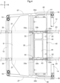
FIG. 4 is a plan view showing the body frame, the seat frame, the battery, and the like. -
FIG. 5 is an exploded left side view showing the body frame, the ROPS frame, the seat frame, the battery, and the like. -
FIG. 6 is a cross-sectional plan view of a sensor support and a hitch attachment section. -
FIGS. 1 to 6 show a multipurpose electric work vehicle, which is an example of a work vehicle. InFIGS. 1 to 6 , F indicates the forward direction, B indicates the backward direction, U indicates the upward direction, D indicates the downward direction, R indicates the rightward direction, and L indicates the leftward direction. - As shown in
FIGS. 1 and2 , the work vehicle includes abody frame 3. Right and leftfront wheels 1 for travel (corresponding to travel devices) are supported by a front portion of thebody frame 3, right and leftrear wheels 2 for travel (corresponding to travel devices) are supported by a rear portion of thebody frame 3, and thebody frame 3 is supported by thefront wheels 1 and therear wheels 2. - A
seating section 4 in which a driver and an operator ride is supported by a portion of thebody frame 3 between thefront wheels 1 and therear wheels 2, and theseating section 4 is surrounded by aROPS frame 5. Theseating section 4 includes a driver's seat 6 (corresponding to a seat), a passenger seat 7 (corresponding to a seat), afloor 8, asteering handle 9 for steering thefront wheels 1, and the like. - The work vehicle includes a
hood 10 in front of theseating section 4 and acargo bed 11 behind theseating section 4. Thecargo bed 11 can be raised and lowered between a use position shown by solid lines inFIG. 1 and a dump position (see two-dot chain lines inFIG. 1 ) at which a front portion of thecargo bed 11 is raised with a lower rear portion of thecargo bed 11 serving as the fulcrum. - As shown in
FIGS. 1 to 4 , thebody frame 3 includesfirst frame sections 21,second frame sections 22,third frame sections 23,fourth frame sections 24,fifth frame sections 25,sixth frame sections 26, andseventh frame sections 27, for example. - The
first frame sections 21 extend along a front-rear direction under the seating section 4 (the floor 8). Thesecond frame sections 22 are coupled to rear portions of thefirst frame sections 21 and extend upward from the rear portions of thefirst frame sections 21. Thethird frame sections 23 are coupled to upper portions of thesecond frame sections 22 and extend rearward from the upper portions of thesecond frame sections 22. - The
fourth frame sections 24 are coupled to the rear portions of thefirst frame sections 21 and extend rearward from the rear portions of thefirst frame sections 21. Aframe 28 extending along a left-right direction is coupled to rear portions of the right and leftfourth frame sections 24.Frames 29 extending along an up-down direction are each coupled to a rear portion of one of thethird frame sections 23 and a rear portion of a corresponding one of thefourth frame sections 24. - The
fifth frame sections 25 are coupled to front portions of thefirst frame sections 21 and extend forward from the front portions of thefirst frame sections 21.Frames 30 extending along the up-down direction are coupled to the front portions of thefirst frame sections 21 and extend upward from the front portions of thefirst frame sections 21. - The
sixth frame sections 26 are coupled to upper portions of theframes 30 and extend forward from the upper portions of theframes 30. Afront guard 12 extends between front portions of thefifth frame sections 25 and front portions of thesixth frame sections 26, and is coupled to the front portions of the fifth andsixth frame sections - As shown in
FIGS. 3 and4 , right and leftfront support sections 15 are coupled to the upper portions of theframes 30, and aframe 13 extending along the left-right direction is coupled to the right and leftfront support sections 15. Aframe 14 extending along the left-right direction is coupled to front portions of the right and leftthird frame sections 23, and right and leftrear support sections 16 are coupled to a right portion and a left portion of theframe 14. - The
seventh frame sections 27 each have a U-shape (a channel shape) in a side view, upper front portions of theseventh frame sections 27 are coupled to thefront support sections 15, and upper rear portions of theseventh frame sections 27 are coupled to therear support sections 16. Thefloor 8 extends between the front portions of thefirst frame sections 21 and lower front portions of theseventh frame sections 27, and is coupled to the front portions of thefirst frame sections 21 and the lower front portions of theseventh frame sections 27. Right and leftside guards 40 each extending from one of therear support sections 16 to a lower rear portion of a corresponding one of theseventh frame sections 27 are coupled to therear support sections 16 and the lower rear portions of theseventh frame sections 27. - As shown in
FIGS. 1 and2 , therear wheels 2 are supported via a suspension mechanism (not shown) by rear portions of thethird frame sections 23 and rear portions of thefourth frame sections 24. Atransmission case 17 is supported by thefourth frame sections 24, and amotor 18 is coupled to a front portion of thetransmission case 17. - An auxiliary transmission (not shown) and a rear wheel differential device (not shown) are provided inside the
transmission case 17. Motive power is transmitted from themotor 18 to the auxiliary transmission, subjected to speed change, and transmitted from the rear wheel differential device to therear wheels 2 viadrive shafts 19. - The
front wheels 1 are supported via a suspension mechanism (not shown) by thefifth frame sections 25 and thesixth frame sections 26, and a front wheeldifferential device 20 is supported by thefifth frame sections 25. Motive power diverted from between the auxiliary transmission and the rear wheel differential device in thetransmission case 17 is transmitted by atransmission shaft 31 to the front wheeldifferential device 20, and then transmitted from the front wheeldifferential device 20 to thefront wheels 1 viadrive shafts 32. - As shown in
FIGS. 2 ,3 , and4 , theROPS frame 5 includes right and leftfirst sections 5a, asecond section 5b, and athird section 5c, for example. - The
first sections 5a of theROPS frame 5 each have an inverted U-shape (an inverted channel shape) in a side view. Thesecond section 5b of theROPS frame 5 extending along the left-right direction is coupled to front portions of the right and leftfirst sections 5a of theROPS frame 5. Thethird section 5c of theROPS frame 5 extending along the left-right direction is coupled to rear portions of the right and leftfirst sections 5a of theROPS frame 5. - Lower front portions of the
first sections 5a of theROPS frame 5 are coupled to thefront support sections 15 with use of bolts (not shown), and lower rear portions of thefirst sections 5a of theROPS frame 5 are coupled to therear support sections 16 with use of bolts (not shown). With this configuration, theROPS frame 5 is attached to thebody frame 3. - The
ROPS frame 5 can be removed from thebody frame 3 by removing the lower front portions of thefirst sections 5a of theROPS frame 5 from thefront support sections 15 and removing the lower rear portions of thefirst sections 5a of theROPS frame 5 from therear support sections 16. - As shown in
FIGS. 3 ,4 , and5 , the work vehicle includes right and left seat frames 33. Eachseat frame 33 is formed into an L-shape (an angle shape) by bending a square pipe, and includes an up-downsection 33a extending along the up-down direction and a front-rear section 33b extending rearward from an upper portion of the up-downsection 33a. - A
support section 33c is coupled to the upper portion of the up-downsection 33a (a front portion of the front-rear section 33b) of eachseat frame 33. Asupport section 33d is coupled to a rear portion of the front-rear section 33b of eachseat frame 33. - An
attachment section 21a is provided in the rear portion of eachfirst frame section 21 of thebody frame 3, and anattachment section 22a is provided in the upper portion of eachsecond frame section 22 of thebody frame 3. - A lower portion of the up-down
section 33a of eachseat frame 33 is attachable to theattachment section 21a of a corresponding one of thefirst frame sections 21 with use of abolt 34 and removable therefrom. A rear portion of the front-rear section 33b of eachseat frame 33 is attachable to theattachment section 22a of a corresponding one of thesecond frame sections 22 with use of abolt 34 and removable therefrom. - As shown in
FIGS. 3 ,4 , and5 , the work vehicle includes asupport frame 35 having a rectangular pipe shape, and a plurality offulcrum sections 35a are provided on thesupport frame 35. Thesupport frame 35 is attachable to thesupport sections 33c of the seat frames 33 with use ofbolts 36 and removable therefrom. - As shown in
FIGS. 1 and2 , the driver'sseat 6 includes aseat section 6a and abackrest section 6b, which are separate from each other, and thepassenger seat 7 includes aseat section 7a and abackrest section 7b, which are separate from each other. - As shown in
FIGS. 3 and5 , the work vehicle includes a flat plate-shapedsupport member 37, andleg sections 37a are provided under a front portion of thesupport member 37. Theseat sections seat 6 and thepassenger seat 7 are attached to thesupport member 37. Theleg sections 37a of thesupport member 37 are attached to thefulcrum sections 35a on thesupport frame 35 in such a manner as to be swingable about an axis extending along the left-right direction. - The work vehicle includes a flat plate-shaped
support member 38, and thebackrest sections seat 6 and thepassenger seat 7 are attached to thesupport member 38. Thesupport member 38 is attachable to the right and leftfirst sections 5a of theROPS frame 5 with use ofbolts 39 and removable therefrom. - With the configuration described above, the front portion of the
support member 37 is supported via thesupport frame 35 by the seat frames 33 and a rear portion of thesupport member 37 is supported by the support sections 3d of the seat frames 33 in a normal use state. - Thus, the
seat section 6a of the driver's seat 6 (seat) and theseat section 7a of the passenger seat 7 (seat) are supported by the seat frames 33 and supported by thebody frame 3 via the seat frames 33. Thebackrest section 6b of the driver'sseat 6 and thebackrest section 7b of thepassenger seat 7 are supported by theROPS frame 5 and supported by thebody frame 3 via theROPS frame 5. - It is possible to open a region above the seat frames 33 by raising the rear portion of the
support member 37 upward with thefulcrum sections 35a on thesupport frame 35 serving as fulcrums. Theseat section 6a of the driver's seat 6 (seat) and theseat section 7a of the passenger seat 7 (seat) can be removed from the seat frames 33 by removing thebolts 36 and removing thesupport frame 35 from the seat frames 33. - The
backrest section 6b of the driver'sseat 6 and thebackrest section 7b of thepassenger seat 7 can be removed from thebody frame 3 by removing thebolts 39 and removing thesupport member 38 from theROPS frame 5. - As shown in
FIGS. 3 ,4 , and5 , a flat plate-shapedsupport member 41 is coupled to the rear portions of thefirst frame sections 21 of thebody frame 3 along the left-right direction. Abattery 42 is attached to thesupport member 41 with use of bolts (not shown) in such a manner as to be removable from thesupport member 41 and attachable thereto. - In the state where the
battery 42 is attached to thesupport member 41, thebattery 42 is between the up-downsection 33a of eachseat frame 33 and thesecond frame sections 22 and between the front-rear section 33b of eachseat frame 33 and thefirst frame sections 21 in a side view. - In a plan view, a
right end portion 42a of thebattery 42 is outward of theright seat frame 33 in the lateral direction and closer to the center of thebody frame 3 in the left-right direction than the rightseventh frame section 27 and theright side guard 40 are. Theright end portion 42a of thebattery 42 overlaps the rightseventh frame section 27 and theright side guard 40 in a side view. - In the plan view, a
left end portion 42b of thebattery 42 is outward of theleft seat frame 33 in the lateral direction and closer to the center of thebody frame 3 in the left-right direction than the leftseventh frame section 27 and theleft side guard 40 are. Theleft end portion 42b of thebattery 42 overlaps the leftseventh frame section 27 and theleft side guard 40 in a side view. - A flat plate-shaped
support member 43 is attached to the front-rear sections 33b of the right and left seat frames 33 with use of bolts (not shown) in such a manner as to be removable from the front-rear sections 33b and attachable thereto. Aninverter 44 and acontrol device 45 are attached to thesupport member 43. Theinverter 44 and thecontrol device 45 are between theseat sections seat 6 and the passenger seat 7 (the support member 37) and the battery 42 (the front-rear sections 33b of the seat frames 33) in a side view. - When a driver seating in the driver's
seat 6 operates a gear shift pedal (not shown), an operation position of the gear shift pedal is input by thecontrol device 45, and theinverter 44 is operated by thecontrol device 45 based on the operation position of the gear shift pedal. DC power output from thebattery 42 is converted into AC power by theinverter 44 and supplied to themotor 18. Themotor 18 operates to output motive power for travel, and the motive power for travel is supplied to thefront wheels 1 and therear wheels 2 as described above. - As shown in
FIGS. 3 ,4 , and5 , when the rear portion of thesupport member 37 is raised upward with thefulcrum sections 35a on thesupport frame 35 serving as fulcrums, the region above the seat frames 33 is opened as described above. - Maintenance of the
inverter 44 and thecontrol device 45 can be performed by raising thesupport member 37. Theinverter 44 and thecontrol device 45 can be removed by removing thesupport member 43 from the seat frames 33. Maintenance of thebattery 42 can be performed by raising thesupport member 37 and removing theinverter 44 and thecontrol device 45. - When the
seat section 6a of the driver's seat 6 (seat) and theseat section 7a of the passenger seat 7 (seat) are removed from the seat frames 33 by removing thesupport frame 35 from the seat frames 33 as described above, the seat frames 33 can be removed from the body frame 3 (thefirst frame sections 21 and the second frame sections 22) by removing thebolts 34. - When the seat frames 33 are removed from the body frame 3 (the
first frame sections 21 and the second frame sections 22), thebattery 42 can be removed from the body frame 3 (the support member 41) and attached to the body frame 3 (the support member 41). - In this case, attachment and removal of the
battery 42 are facilitated when thesupport member 38 is removed from theROPS frame 5 by removing thebolts 39 as described above to remove thebackrest section 6b of the driver'sseat 6 and thebackrest section 7b of thepassenger seat 7 from thebody frame 3. - Attachment and removal of the
battery 42 are further facilitated when theROPS frame 5 is removed from thebody frame 3 by removing the lower front portions of thefirst sections 5a of theROPS frame 5 from thefront support sections 15 and removing the lower rear portions of thefirst sections 5a of theROPS frame 5 from therear support sections 16 as described above, in addition to removing thebackrest section 6b of the driver'sseat 6 and thebackrest section 7b of thepassenger seat 7 from thebody frame 3. - As shown in
FIGS. 1 and2 , ahitch attachment section 46 having a rectangular pipe shape is provided at front end portions of thefifth frame sections 25 of thebody frame 3, and ahitch attachment section 47 having a rectangular pipe shape is provided at rear end portions of the fourth frame sections 24 (the frame 28) of thebody frame 3. - A work device (not shown) can be attached to a front portion or a rear portion (both the front portion and the rear portion) of the
body frame 3 by attaching a hitch (not shown) for attaching the work device to thehitch attachment section hitch attachment section - When a hitch (not shown) for towing is attached to the rear
hitch attachment section 47, a wagon (not shown) can be connected to the hitch and towed by the work vehicle. - When the work vehicle fails to travel on soft ground, the hitch for towing can be attached to the
hitch attachment section hitch attachment section - As shown in
FIGS. 1 and2 , the work vehicle includes sensor supports 48. Eachsensor support 48 includes afirst section 48a extending along the left-right direction and asecond section 48b attached to a center portion of thefirst section 48a in the left-right direction and extending along the front-rear direction.Obstacle sensors first section 48a. - The
second sections 48b of the sensor supports 48 are inserted into thehitch attachment sections hitch attachment sections body frame 3. - The work vehicle includes fixing
members 49, and as shown inFIG. 6 , each fixingmember 49 includes abody 49a, ahandle portion 49b, a receivingportion 49c, and aretainer portion 49d, for example. - The
body 49a of each fixingmember 49 is formed like a pin. Thehandle portion 49b to be held by a worker extends from an end portion of thebody 49a in a direction intersecting with thebody 49a. The receivingportion 49c like a washer is fixed to an intermediate portion of thebody 49a. Theretainer portion 49d is formed like a beta pin and attachable to an end portion of thebody 49a and removable therefrom. - After the
second sections 48b of the sensor supports 48 are inserted into thehitch attachment sections bodies 49a of the fixingmembers 49 are inserted into openings in thehitch attachment sections second sections 48b of the sensor supports 48 until the receivingportions 49c of the fixingmembers 49 abut against thehitch attachment sections retainer portions 49d of the fixingmembers 49 are attached to the end portions of thebodies 49a. Thus, the sensor supports 48 can be attached and fixed to thehitch attachment sections - When the
retainer portions 49d of the fixingmembers 49 are removed from thebodies 49a and the fixingmembers 49 are removed from thehitch attachment sections second sections 48b of the sensor supports 48 can be pulled out from thehitch attachment sections hitch attachment sections - As shown in
FIGS. 1 and2 , an obstacle sensor 51 (corresponding to a first obstacle sensor) is supported by a center portion of thefirst section 48a of eachsensor support 48 in the left-right direction. - Obstacle sensors 52 (corresponding to second obstacle sensors) are supported by portions of the
first section 48a of eachsensor support 48 on the right side and the left side of theobstacle sensor 51. - The
obstacle sensor 51 is configured to detect obstacles with use of infrared rays or ultrasonic waves, and mainly detects obstacles spaced apart from thebody frame 3 in front of (or behind) thebody frame 3. - Each
obstacle sensor 52 is provided with a flat plate-shapedcontact body 50, and detects an obstacle in response to thecontact body 50 coming into contact with the obstacle. Thecontact bodies 50 of theobstacle sensors 52 slightly protrude forward (rearward) from theobstacle sensor 51 in a plan view. - In the state where the sensor supports 48 are attached to the
hitch attachment sections first sections 48a of the sensor supports 48 extend from the rightfront wheel 1 to the leftfront wheel 1 and from the rightrear wheel 2 to the leftrear wheel 2. - When the sensor supports 48 are attached to the
hitch attachment sections first section 48a of thefront sensor support 48 are in front of the right and leftfront wheels 1. Right and left portions of thefirst section 48a of therear sensor support 48 are behind the right and leftrear wheels 2. - In the state where the
front sensor support 48 is attached to thehitch attachment section 46, the front sensor support 48 (thecontact bodies 50 of the obstacle sensors 52) is slightly forward of a front end portion of thefront guard 12 in a side view. - In the state where the
rear sensor support 48 is attached to thehitch attachment section 47, the rear sensor support 48 (thecontact bodies 50 of the obstacle sensors 52) is slightly forward of a rear end portion of thecargo bed 11 in the use state (the state shown by solid lines inFIG. 1 ) or is substantially at the same position as the rear end portion of thecargo bed 11 in a side view. Therefore, even when thecargo bed 11 is moved to the dump position and soil on thecargo bed 11 is discharged downward, the soil discharged from thecargo bed 11 is unlikely to come into contact with the rear sensor support 48 (theobstacle sensors 51 and 52). - A configuration is also possible in which the sensor support 48 (the
obstacle sensors 51 and 52) is attached to the fronthitch attachment section 46 and is not attached to the rearhitch attachment section 47. - A configuration is also possible in which the sensor support 48 (the
obstacle sensors 51 and 52) is attached to the rearhitch attachment section 47 and is not attached to the fronthitch attachment section 46. - A configuration is also possible in which right and left
hitch attachment sections 46 are provided next to each other in the left-right direction at the front end portions of thefifth frame sections 25 of thebody frame 3, and right and lefthitch attachment sections 47 are provided next to each other in the left-right direction at the rear end portions of the fourth frame sections 24 (the frame 28) of thebody frame 3. - In this case, two
second sections 48b can be attached to thefirst section 48a of eachsensor support 48. By inserting the twosecond sections 48b of thesensor support 48 into the right and left hitch attachment sections 46 (the right and left hitch attachment sections 47), the sensor support 48 (thefirst section 48a) is firmly attached to thebody frame 3. - In a case where the
obstacle sensor 51 configured to detect obstacles with use of infrared rays or ultrasonic waves is provided in thefirst section 48a of thesensor support 48 and the contact-type obstacle sensors 52 are not provided, the length of thefirst section 48a of thesensor support 48 may be shorter than the width between the right and left front wheels 1 (rear wheels 2). - Crawler-type travel devices (not shown) may be provided as front travel devices, instead of the
front wheels 1. Crawler-type travel devices (not shown) may be provided as rear travel devices, instead of therear wheels 2. Afront wheel 1 and arear wheel 2 may be replaced with one crawler-type travel device (not shown). - The present invention is applicable to not only an electric work vehicle that drives a travel device with use of a motor but also a hybrid work vehicle that drives a travel device with use of an engine and a motor, as well as a work vehicle only equipped with an engine, rather than an electric work vehicle and a hybrid work vehicle.
-
- 1
- Front wheel (travel device)
- 2
- Rear wheel (travel device)
- 3
- Body frame
- 46
- Hitch attachment section
- 47
- Hitch attachment section
- 48
- Sensor support
- 48a
- First section
- 48b
- Second section
- 51
- Obstacle sensor (first obstacle sensor)
- 52
- Obstacle sensor (second obstacle sensor)
Claims (5)
- A work vehicle comprising:a body frame (3) provided with at least one travel device (1, 2);a hitch attachment section (46, 47) configured to enable attachment and removal of a hitch for attaching a work device and a hitch for towing, the hitch attachment section (46, 47) being in a front portion or a rear portion of the body frame (3); anda sensor support (48) supporting at least one obstacle sensor (51, 52) for detecting an obstacle, and configured to be attached to the hitch attachment section (46, 47) and removed from the hitch attachment section (46, 47).
- The work vehicle according to claim 1,wherein the sensor support (48) includes:a first section (48a) supporting the at least one obstacle sensor (51, 52) and extending along a left-right direction; anda second section (48b) attached to the first section (48a) and extending along a front-rear direction,wherein the sensor support (48) is attached to the hitch attachment section (46, 47) by inserting the second section (48b) into the hitch attachment section (46, 47).
- The work vehicle according to claim 2,
wherein the at least one obstacle sensor includes:a first obstacle sensor (51) configured to detect an obstacle with use of infrared rays or ultrasonic waves, and supported by the first section (48a); anda left second obstacle sensor (52) and a right second obstacle sensor (52) each configured to detect an obstacle by coming into contact with the obstacle, the left second obstacle sensor (52) being supported by a portion of the first section (48a) on a left side of the first obstacle sensor (51), and the right second obstacle sensor (52) being supported by a portion of the first section (48a) on a right side of the first obstacle sensor (51). - The work vehicle according to claim 2 or 3,wherein the at least one travel device includes a front travel device (1) and a rear travel device (2), andafter the sensor support (48) is attached to the hitch attachment section (46, 47), the first section (48a) is in front of the front travel device (1) or behind the rear travel device (2).
- The work vehicle according to claim 4,
wherein the at least one travel device includes a right travel device (1, 2) and a left travel device (1, 2), and the first section (48a) is long enough to extend from the right travel device (1, 2) to the left travel device (1, 2).
Applications Claiming Priority (1)
| Application Number | Priority Date | Filing Date | Title |
|---|---|---|---|
| JP2022181286A JP7817145B2 (en) | 2022-11-11 | 2022-11-11 | Work vehicle |
Publications (1)
| Publication Number | Publication Date |
|---|---|
| EP4369041A1 true EP4369041A1 (en) | 2024-05-15 |
Family
ID=88689554
Family Applications (1)
| Application Number | Title | Priority Date | Filing Date |
|---|---|---|---|
| EP23207704.0A Pending EP4369041A1 (en) | 2022-11-11 | 2023-11-03 | Work vehicle |
Country Status (3)
| Country | Link |
|---|---|
| US (1) | US20240157742A1 (en) |
| EP (1) | EP4369041A1 (en) |
| JP (1) | JP7817145B2 (en) |
Citations (5)
| Publication number | Priority date | Publication date | Assignee | Title |
|---|---|---|---|---|
| DE102009048380A1 (en) * | 2009-10-06 | 2011-04-07 | GM Global Technology Operations, Inc., Detroit | Parking assistance system for motor vehicle, has connector plugging device whose connection socket is controlled such that automatic switching of vehicle-lateral sensors to trailer sensors is provided by connector plugging device |
| JP2017013692A (en) | 2015-07-02 | 2017-01-19 | 株式会社クボタ | Multipurpose work vehicle |
| US20190217831A1 (en) * | 2018-01-18 | 2019-07-18 | Vieletech Inc. | Smart trailer controller |
| US20190235519A1 (en) * | 2018-01-30 | 2019-08-01 | Uber Technologies, Inc. | Intermediate mounting component and sensor system for a mansfield bar of a cargo trailer |
| EP3822098A1 (en) * | 2019-11-14 | 2021-05-19 | Valeo Schalter und Sensoren GmbH | Method for configuring a trailer detection system |
Family Cites Families (2)
| Publication number | Priority date | Publication date | Assignee | Title |
|---|---|---|---|---|
| DE102011053505A1 (en) * | 2011-09-12 | 2013-03-14 | Scambia Holdings Cyprus Ltd. | support unit |
| US11135883B2 (en) * | 2019-05-13 | 2021-10-05 | Magna Electronics Inc. | Vehicular sensing system with ultrasonic sensor at trailer hitch |
-
2022
- 2022-11-11 JP JP2022181286A patent/JP7817145B2/en active Active
-
2023
- 2023-11-03 EP EP23207704.0A patent/EP4369041A1/en active Pending
- 2023-11-03 US US18/386,754 patent/US20240157742A1/en active Pending
Patent Citations (5)
| Publication number | Priority date | Publication date | Assignee | Title |
|---|---|---|---|---|
| DE102009048380A1 (en) * | 2009-10-06 | 2011-04-07 | GM Global Technology Operations, Inc., Detroit | Parking assistance system for motor vehicle, has connector plugging device whose connection socket is controlled such that automatic switching of vehicle-lateral sensors to trailer sensors is provided by connector plugging device |
| JP2017013692A (en) | 2015-07-02 | 2017-01-19 | 株式会社クボタ | Multipurpose work vehicle |
| US20190217831A1 (en) * | 2018-01-18 | 2019-07-18 | Vieletech Inc. | Smart trailer controller |
| US20190235519A1 (en) * | 2018-01-30 | 2019-08-01 | Uber Technologies, Inc. | Intermediate mounting component and sensor system for a mansfield bar of a cargo trailer |
| EP3822098A1 (en) * | 2019-11-14 | 2021-05-19 | Valeo Schalter und Sensoren GmbH | Method for configuring a trailer detection system |
Also Published As
| Publication number | Publication date |
|---|---|
| US20240157742A1 (en) | 2024-05-16 |
| JP2024070660A (en) | 2024-05-23 |
| JP7817145B2 (en) | 2026-02-18 |
Similar Documents
| Publication | Publication Date | Title |
|---|---|---|
| US12012000B2 (en) | Side-by-side ATV | |
| US10011189B2 (en) | Side-by-side ATV | |
| EP1943138A1 (en) | A fifth wheel assembly for coupling a trailer to a truck tractor and a method for operating said assembly | |
| KR100589827B1 (en) | Shock-absorbing structure of steering device of car | |
| US20250282235A1 (en) | Electric work vehicle | |
| US20240157742A1 (en) | Work Vehicle | |
| EP4368429A1 (en) | Work vehicle | |
| US20250286321A1 (en) | Electric work vehicle | |
| DE102008014641B4 (en) | tractor | |
| EP3795413B1 (en) | Multipurpose work vehicle | |
| EP4644160A1 (en) | Work vehicle | |
| US12337780B2 (en) | Working vehicle | |
| JP2024070662A (en) | Work vehicle | |
| JP2024070663A (en) | Work vehicle | |
| CN107416050B (en) | Tractor vehicle | |
| EP1026072A1 (en) | Vehicle, vehicle combination and method for steering a vehicle | |
| JP2009262727A (en) | Hood opening and closing device of working vehicle | |
| JPH10210U (en) | Power work vehicle | |
| JPH0617408U (en) | Agricultural machine trailer device and agricultural machine |
Legal Events
| Date | Code | Title | Description |
|---|---|---|---|
| PUAI | Public reference made under article 153(3) epc to a published international application that has entered the european phase |
Free format text: ORIGINAL CODE: 0009012 |
|
| STAA | Information on the status of an ep patent application or granted ep patent |
Free format text: STATUS: REQUEST FOR EXAMINATION WAS MADE |
|
| 17P | Request for examination filed |
Effective date: 20231103 |
|
| AK | Designated contracting states |
Kind code of ref document: A1 Designated state(s): AL AT BE BG CH CY CZ DE DK EE ES FI FR GB GR HR HU IE IS IT LI LT LU LV MC ME MK MT NL NO PL PT RO RS SE SI SK SM TR |