EP4368913A1 - Compact solar system - Google Patents
Compact solar system Download PDFInfo
- Publication number
- EP4368913A1 EP4368913A1 EP23206241.4A EP23206241A EP4368913A1 EP 4368913 A1 EP4368913 A1 EP 4368913A1 EP 23206241 A EP23206241 A EP 23206241A EP 4368913 A1 EP4368913 A1 EP 4368913A1
- Authority
- EP
- European Patent Office
- Prior art keywords
- heat transfer
- transfer fluid
- solar system
- hydraulic circuit
- heat exchange
- Prior art date
- Legal status (The legal status is an assumption and is not a legal conclusion. Google has not performed a legal analysis and makes no representation as to the accuracy of the status listed.)
- Granted
Links
Images







Classifications
-
- F—MECHANICAL ENGINEERING; LIGHTING; HEATING; WEAPONS; BLASTING
- F24—HEATING; RANGES; VENTILATING
- F24S—SOLAR HEAT COLLECTORS; SOLAR HEAT SYSTEMS
- F24S60/00—Arrangements for storing heat collected by solar heat collectors
- F24S60/30—Arrangements for storing heat collected by solar heat collectors storing heat in liquids
-
- F—MECHANICAL ENGINEERING; LIGHTING; HEATING; WEAPONS; BLASTING
- F24—HEATING; RANGES; VENTILATING
- F24S—SOLAR HEAT COLLECTORS; SOLAR HEAT SYSTEMS
- F24S10/00—Solar heat collectors using working fluids
- F24S10/40—Solar heat collectors using working fluids in absorbing elements surrounded by transparent enclosures, e.g. evacuated solar collectors
- F24S10/45—Solar heat collectors using working fluids in absorbing elements surrounded by transparent enclosures, e.g. evacuated solar collectors the enclosure being cylindrical
-
- F—MECHANICAL ENGINEERING; LIGHTING; HEATING; WEAPONS; BLASTING
- F24—HEATING; RANGES; VENTILATING
- F24S—SOLAR HEAT COLLECTORS; SOLAR HEAT SYSTEMS
- F24S40/00—Safety or protection arrangements of solar heat collectors; Preventing malfunction of solar heat collectors
- F24S40/50—Preventing overheating or overpressure
- F24S40/58—Preventing overpressure in working fluid circuits
-
- F—MECHANICAL ENGINEERING; LIGHTING; HEATING; WEAPONS; BLASTING
- F24—HEATING; RANGES; VENTILATING
- F24S—SOLAR HEAT COLLECTORS; SOLAR HEAT SYSTEMS
- F24S50/00—Arrangements for controlling solar heat collectors
- F24S50/40—Arrangements for controlling solar heat collectors responsive to temperature
-
- F—MECHANICAL ENGINEERING; LIGHTING; HEATING; WEAPONS; BLASTING
- F24—HEATING; RANGES; VENTILATING
- F24S—SOLAR HEAT COLLECTORS; SOLAR HEAT SYSTEMS
- F24S80/00—Details, accessories or component parts of solar heat collectors not provided for in groups F24S10/00-F24S70/00
- F24S80/30—Arrangements for connecting the fluid circuits of solar collectors with each other or with other components, e.g. pipe connections; Fluid distributing means, e.g. headers
-
- F—MECHANICAL ENGINEERING; LIGHTING; HEATING; WEAPONS; BLASTING
- F24—HEATING; RANGES; VENTILATING
- F24S—SOLAR HEAT COLLECTORS; SOLAR HEAT SYSTEMS
- F24S90/00—Solar heat systems not otherwise provided for
- F24S90/10—Solar heat systems not otherwise provided for using thermosiphonic circulation
Definitions
- the present invention concerns a compact solar system.
- the present invention concerns a compact solar system comprising a hydraulic circuit adapted to activate or deactivate an area of thermal energy storage.
- solar systems for the production of domestic hot water are known, which are divided into two macro-families: forced circulation systems and natural circulation systems.
- the former provide solar collectors (hereinafter also called just collectors) connected, via a hydraulic circuit with circulator, to an insulated energy storage located in a technical room.
- the energy storage element is generally placed near the collector and the energy collected by the collector is transferred on site to the storage, by natural circulation.
- solar energy is collected by collecting surfaces (S), covered by highly selective material which transmit part of this energy to an energy storage volume (V) containing a primary heat transfer fluid, for example technical water, or directly a secondary fluid, such as domestic hot water (DHW).
- a primary heat transfer fluid for example technical water
- DHW domestic hot water
- the system receives solar energy in the form of light (electromagnetic) energy and stores part of this energy in the form of thermal energy, increasing the temperature of the fluid stored in the storage tank; generally the outer surface of the storage itself actively participates in the solar energy absorption stage, or in any case the collector and the storage are integrated and are not clearly distinguishable from the outside, all forming a compact system.
- the state of the art of ICS systems provides for the division into two families of systems based on the method of control of heat dispersions towards the environment: in the former, heat dispersions are reduced by using a glass cover (for example in patent documents EP 2 746 692 A1 , EP 2 924 364 B1 ), in the latter by using vacuum gaps in order to cancel convective motions.
- a glass cover for example in patent documents EP 2 746 692 A1 , EP 2 924 364 B1
- vacuum gaps in order to cancel convective motions.
- glass pipes having vacuum gaps are used both as elements collecting solar energy and as elements containing the storage of hot water. In fact, inside them there is the storage or hydraulic tank where the energy absorbed by the selective collecting surface and stored in the glass pipes is transferred.
- the upper limit of the temperature of the storage fluid is fixed at approximately 90° - 99°C. Beyond this limit it is necessary to adopt a protection system.
- this protection system consists of dissipating the thermal energy generated, originating from the collection of solar radiations, when the storage temperature reaches its limit values.
- V volume of the stored fluid
- S collecting surface
- V/S the value of the ratio between storage volume and collection surface
- the solar energy may not be sufficient to heat the system and therefore to guarantee the withdrawal of DHW at the minimum design temperature (typically the system must deliver hot water at a temperature not lower than 40°C - 50°C).
- the V/S value is too low, the heating process leads to frequent overtemperature conditions; this is because the collected solar energy corresponds to a low storage volume, therefore, there is a greater risk of increasing the fluid temperature to unacceptable values.
- the aim of the present invention is to maximise all the solar energy incident on the system, by reducing the dissipation of the incident energy to a minimum, without compromising the performance of the system throughout the year, under both more unfavourable weather conditions and favourable weather conditions.
- an aim of the present invention is to allow the compact solar system to store excess energy, without reaching the maximum operating temperature values.
- Another aim of the present invention is to allow a rapid heating of the compact solar system under any condition of irradiation and user profile.
- an aim of the present invention is to operate the system, as far as possible, at an average temperature of the stored fluid lower than 75°C, which allows the efficiency of the system itself to be increased (less dispersions towards the environment), to limit the thermal stress of the system components and reduce the limescale formation processes.
- An object of the present invention is a compact solar system for heating a first heat transfer fluid; said solar system includes an external frame, inside which the following elements are contained: a main tank for containing a heat transfer fluid; collecting means for collecting the incident solar radiation, which, being in heat exchange with said main tank, make it possible to transfer the collected thermal energy to the heat transfer fluid stored in the main tank; and a first hydraulic circuit for the circulation of the first heat transfer fluid, which includes an inlet portion for the inlet of the first heat transfer fluid and an outlet portion for the outlet of the first heat transfer fluid.
- the solar system is characterised in that it includes an additional tank inside the frame to contain a heat transfer fluid, thermally isolated from the collecting means, and in that the volumetric ratio between the volume of the additional tank and the volume of the main tank is defined by the following relationship: 0.3 ⁇ V 4 V 3 ⁇ 1.3 , where V 3 is the volume of the main tank and V 4 is the volume of the additional tank.
- the first hydraulic circuit provides a first heat exchange portion, in heat exchange with the heat transfer fluid contained in the additional tank, and a second heat exchange portion in heat exchange with the heat transfer fluid contained in the main tank.
- the first and second heat exchange portions are in fluid connection with each other via a connecting conduit and a first return conduit.
- the compact solar system is characterised in that it provides flow adjusting means, arranged in the first hydraulic circuit, to allow the circulation of the first heat transfer fluid from the second heat exchange portion to the first heat exchange portion through the first return conduit, when a threshold temperature of a heat transfer fluid contained in the main tank is reached.
- the first heat exchange portion of the first hydraulic circuit can be the additional tank.
- the additional tank can therefore be adapted to contain the first heat transfer fluid, and be in fluid connection with the connecting conduit and with the first return conduit of the first hydraulic circuit and with the inlet portion.
- the second heat exchange portion of the first hydraulic circuit can be the main tank, which can be adapted to contain the first heat transfer fluid and be in fluid connection with the connecting conduit and the first return conduit of the first hydraulic circuit and with the outlet portion.
- the main tank can contain a second heat transfer fluid, not in fluid connection with the first heat transfer fluid.
- the solar system can include a second hydraulic circuit for the circulation of the second heat transfer fluid.
- the second hydraulic circuit can be a closed circuit composed of the main tank and a recirculation conduit.
- the solar system can include a heat exchanger, wherein the recirculation conduit of the second hydraulic circuit and the second heat exchange portion of the first hydraulic circuit can be arranged, in heat exchange with each other.
- the solar system can include a second circulation pump arranged in the second hydraulic circuit, to be able to activate the circulation of said second heat transfer fluid in said second hydraulic circuit. Furthermore, it can include means for detecting the circulation of the first heat transfer fluid, in particular a flow switch, in the first hydraulic circuit. Said detecting means can be in connection with the second circulation pump and the solar system can furthermore be configured to activate/deactivate said second circulation pump on the basis of the values detected by the detecting means.
- the second heat exchange portion of the first hydraulic circuit can be arranged inside the main tank.
- the additional tank can contain a second heat transfer fluid, not in fluid connection with the first heat transfer fluid, wherein the first heat exchange portion of the first hydraulic circuit can be arranged inside the additional tank itself.
- the flow adjusting means arranged in the first hydraulic circuit, can be a first circulation pump and a non-return valve, wherein said non-return valve can be arranged on the first return conduit between the two heat exchange portions.
- the first circulation pump can be arranged on one of the connecting or return conduits, between said two (first and second) heat exchange portions.
- the flow adjusting means can be arranged in the first hydraulic circuit and can be a thermostatic valve or an electrovalve, arranged in the first return conduit, between said two heat exchange portions.
- the main tank can include a plurality of main storage ducts in fluid connection with each other.
- the second heat exchange portion can include a plurality of heat exchange conduits, in fluid connection with each other; each of which can be inserted into a respective main storage duct of the main tank.
- the collecting means of the solar system can be a plurality of pipes having an outer vacuum gap.
- each main storage duct of the main tank can be inserted into a respective pipe having an outer vacuum gap.
- the additional tank can include at least two additional storage ducts in fluid connection with each other.
- the ratio between the sum of the volumes of the main and additional tanks and the surface of the collecting means is defined by the following relationship: 50 lit m 2 ⁇ V 3 + V 4 S ⁇ 130 lit m 2 , where V 3 +V 4 represents the sum of the volumes of the main and additional tanks while S represents the surface of the collecting means.
- the solar system can include a control unit connected to the flow adjusting means arranged in the first hydraulic circuit.
- the control unit can be configured to act on the flow adjusting means on the basis of the temperature of the heat transfer fluid contained in the main tank, when said threshold temperature is reached.
- the solar system can include temperature detecting means, arranged in said main tank, for detecting the temperature of the heat transfer fluid contained therein.
- the flow adjusting means can include a thermal switch, for detecting the temperature of the heat transfer fluid contained in the main tank, and a first circulation pump electrically connected to said thermal switch.
- said first circulation pump can be arranged in the first hydraulic circuit and the thermal switch can be arranged in the main tank, in direct or indirect contact with the heat transfer fluid contained therein.
- the temperature detecting means or the thermal switch can be inserted into a possible thermowell.
- the solar system can be adapted to assume a first use configuration, wherein the first heat transfer fluid can be adapted to flow into said first hydraulic circuit from the inlet portion to the outlet portion, passing through the first and the second heat exchange portion passing only through the connecting conduit. Furthermore, the solar system can assume a second use configuration, wherein the first heat transfer fluid can circulate in the first hydraulic circuit between the first and second heat exchange areas, passing through both the connecting conduit and the first return conduit. Furthermore, during use, the solar system can assume said second use configuration when the temperature of the heat transfer fluid contained in the main tank exceeds said threshold temperature.
- the process of heating a fluid by compact solar systems depends on the ratio between the volume of the stored fluid (V) and the collecting surface (S).
- a secondary circuit for heating a secondary fluid by heat exchange with a primary fluid for example by a heat exchanger
- a primary fluid for example by a heat exchanger
- having a primary fluid at 45 - 50°C is not sufficient to guarantee a heat exchange with the secondary circuit such as to bring it to design DHW conditions of 40°C - 50°C, unless using a heat exchanger having a high exchange surface, which would make the objective of creating a compact system difficult and would also be anti-economic.
- the solar system according to the present invention provides the possibility of having a dynamic V/S ratio value over time, therefore variable depending on weather conditions.
- the solar system 1 is of the compact type, as previously described, and is adapted to heat a first heat transfer fluid, in particular a secondary fluid, for example domestic hot water (DHW).
- a first heat transfer fluid in particular a secondary fluid, for example domestic hot water (DHW).
- the solar system 1 includes an external frame 200, inside which the following elements are contained, described herein below.
- a main tank 3 necessary to contain a heat transfer fluid, collecting means 2 for collecting the solar radiation incident on them, a first hydraulic circuit 7 for the circulation of the first heat transfer fluid, and an additional tank 4 for containing a heat transfer fluid.
- the main tank 3 and the additional tank 4 are adapted to contain the same heat transfer fluid, in particular said first heat transfer fluid.
- a second heat transfer fluid can be provided, possibly contained in one of the two tanks.
- the collecting means 2 are in heat exchange with the main tank 3 in order to transfer the collected thermal energy to the heat transfer fluid contained in the main tank 3.
- the first hydraulic circuit 7 in turn includes an inlet portion 79 for the inlet of the first incoming heat transfer fluid and an outlet portion 80 for the outlet of the first outgoing heat transfer fluid on the user side.
- the additional tank 4 is thermally insulated from the collecting means 2.
- the main tank 3 and the additional tank 4 are such that the volumetric ratio between their respective volumes V 3 and V 4 is defined by the following relationship: 0.3 ⁇ V 4 V 3 ⁇ 1.3 .
- the first hydraulic circuit 7 provides a first heat exchange portion 4, which is in heat exchange with the heat transfer fluid contained in said additional tank 4, and a second heat exchange portion 3, which instead is in heat exchange with the heat transfer fluid contained in the main tank 3.
- Said first 4, 94' and second 3, 94 heat exchange portions are in fluid connection with each other via a connecting conduit 71 and a first return conduit 75.
- the two heat exchange portions coincide respectively with the additional tank 4 and the main tank 3, as both are adapted to contain the same first heat transfer fluid which, by circulating and mixing between the two tanks at different temperatures, act as heat exchange areas.
- the compact solar system 1 also provides flow adjusting means 5, 6 arranged in the first hydraulic circuit 7, used in order to allow the circulation of the first heat transfer fluid from the second heat exchange portion 3 to the first heat exchange portion 4 through said first return conduit 75, when a threshold temperature T s of a heat transfer fluid contained in said main tank 3 is reached.
- said solar system 1 can be adapted to assume a first use configuration wherein the first heat transfer fluid is adapted to flow into said first hydraulic circuit 7 from said inlet portion 79 to said outlet portion 80 through said first 4 and second 3 heat exchange portions passing only through said connecting conduit 71, and a second use configuration wherein the first heat transfer fluid circulates into said first hydraulic circuit 7 between said first 4 and second 3 heat exchange areas passing through both said connecting conduit 71 and first return conduit 75.
- said solar system 1 assumes said second use configuration when the temperature T 3 of the heat transfer fluid contained in the main tank 3 exceeds said threshold temperature T s .
- the collecting means are a plurality of vacuum collecting pipes 2 having an outer gap.
- the collecting means can be of a different type, for example the main tank 3 can be directly painted with a highly selective material and protected by a non-vacuum glass cover, or the collecting means can be absorbers consisting of a sheet of metallic material coated by a highly selective material, which is placed in heat exchange with the main tank 3.
- the main tank 3 includes a plurality of main storage ducts 31, in fluid connection with each other, for the storage of the secondary fluid to be heated.
- a corresponding main storage duct 31 is preferably arranged inside each collecting vacuum pipe 2 with an outer gap. Said plurality of main storage ducts 31 are in fluid connection with each other, via a plurality of further connecting conduits 74, to form the main tank 3.
- the additional tank 4 which is in fluid connection with said main tank 3, is arranged adjacent thereto, preferably in the lower portion of the solar system 1.
- Said additional tank 4 can include one or more additional storage ducts in fluid connection with each other or a single duct, as shown for the first embodiment.
- Said additional tank 4 is shielded from solar radiation by a suitable opaque surface (which can also be the frame 200 of the system 1 itself) and is suitably insulated to reduce heat dissipation towards the environment external to the tank 4 itself.
- Said additional tank 4 is separated from the main tank 3 and the separation space is suitably insulated.
- the additional tank 4 can be arranged in the upper part of the solar system 1, in the lower part of the solar system 1 or in any central area of the solar system 1, both in a horizontal position and in a vertical position if it is elongated in shape.
- the additional tank 4 can have a cylindrical shape but also any shape that ensures a structural resistance to the hydraulic pressure of the contained fluid.
- the material of the additional tank 4 can be stainless steel but also any material that is compatible with the temperatures and intended use of the contained fluid.
- the first hydraulic circuit 7 includes said additional tank 4, said plurality of main storage ducts 31 and said plurality of further connecting conduits 74. Furthermore, said first hydraulic circuit 7 provides a connecting conduit 71 for the fluid connection of the additional tank 4, in correspondence with an additional outlet portion 72 of said additional tank 4, with said main tank 3, in particular with at least one duct of said plurality of main storage ducts 31, in correspondence with a main inlet portion 73 of said main tank 3, in particular of a duct of said plurality of main storage ducts 31.
- said first hydraulic circuit 7 includes a first return conduit 75 for the fluid connection of the main tank 3, in correspondence with its main outlet portion 76, with the additional inlet portion 78 of said additional tank 4.
- a first circulation pump 5 adapted to move the first heat transfer fluid from said main tank 3 to said additional tank 4.
- Said first circulation pump 5 can be connected to a control unit (as shown for the first control system in Figure 11a ).
- a different control system can be provided wherein the first circulation pump 5 is connected to a thermal switch which activates it depending on the temperature value detected by the switch itself (as shown in Figure 11b ).
- said first return conduit 75 in turn comprises a non-return valve 6, arranged between said two heat exchange portions 3 and 4, in particular it is arranged between said main outlet portion 76 of the main tank 3 and said additional inlet portion 78 of the additional tank 4.
- the first heat transfer fluid is withdrawn from the outlet portion 80, the first heat transfer fluid is simultaneously introduced through the inlet portion 79 at the same flow rate.
- the additional tank 4 acts solely as an inlet passage conduit for the first heat transfer fluid coming from the hydraulic grid.
- the solar system 1 is able to assume a second use configuration (shown in Figure 5a ), if temperature conditions are reached such that said solar system 1 risks overheating.
- the additional tank 4 and said first dedicated hydraulic circuit 7, in particular thanks to the first return conduit 75 it is possible to also make the additional tank 4 participate in the storage of solar energy and therefore to increase or decrease the value of the V/S ratio of the solar system 1 according to the invention on the basis of the weather conditions, since the collected solar energy can be redistributed not only in the volume V 3 of the main tank 3, but also in the volume V 4 of the additional tank 4.
- the fluid connection between the main tank 3 and the additional tank 4 is activated also via the first return conduit 75 of said first hydraulic circuit 7, (as shown in Figure 5a ) by activation of flow management means 5, for example said first circulation pump 5, which were deactivated in said first use configuration.
- flow management means 5 for example said first circulation pump 5, which were deactivated in said first use configuration.
- the first hydraulic circuit 7 becomes a closed circuit wherein the first heat transfer fluid by passing through the first return conduit 75, which acts as a recirculation conduit, allows the circulation of the first heat transfer fluid between the two tanks 3 and 4, thus also heating the first heat transfer fluid contained in the additional tank 4.
- This transfer can take place via passive control, for example by opening and closing of electromechanical elements, or active control, for example via electronics and control logic.
- Figures 11a, 11b and 11c show three variants of the embodiment of Figure 3a associated with alternative control systems for describing some principles of activation of the circulation conduits in the recirculation branches, in particular in the first return conduit 75, arranged for transferring energy between the main tank 3 and the additional tank 4.
- Figure 11a shows a schematic showing a first control system for controlling the first circulation pump 5 via a control unit or control panel 100.
- the control unit 100 has means for detecting the temperature 102, in particular a temperature sensor 102, which detect the value of the temperature T 3 of the fluid contained in the main tank 3, in particular in one of the ducts of said plurality of main storage ducts 31, which is compared with the value of the threshold temperature T s .
- the comparison can be made via threshold/hysteresis logic or via more complex logics, such as PID, PD, PI.
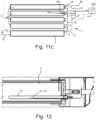
- the temperature sensor 102 can be either in direct or indirect contact with the fluid contained in the main tank 3 or more simply in indirect contact with this fluid, for example by placing it in a thermowell 101 (as shown in Figure 12 ) or in contact with the material of which the ducts of said plurality of main storage ducts 31 are made. Therefore, the control unit 100 decides whether to activate the second use configuration, by electrically powering the first circulation pump 5 or not.
- the first circulation pump 5 therefore guarantees the hydraulic head useful for circulating the fluid (by putting the fluid under pressure) through the non-return valve 6 and overcoming pressure losses throughout the recirculation circuit.
- a second control system comprising a thermal switch 103 which detects the temperature T 3 of the fluid contained in the main tank 3 or more simply in indirect contact with this fluid, for example by placing it in a thermowell 101, in particular in the plurality of main storage ducts 31, and on the basis of this value the thermal switch 103 closes or not the electrical power circuit of the first circulation pump 5.
- the thermal switch 103 is preferably arranged in indirect contact with the fluid contained in the plurality of main storage ducts 31, for example by inserting it into a thermowell 101 (as shown in Figure 12 ) or in contact with the material of which the ducts of said plurality of main storage ducts 31 are made.
- Figure 11c shows an alternative schematic of the system including a third control system, wherein in the first return conduit 75 there is an electrovalve 6".
- the latter if de-powered, is able to stop the circulation of the heat transfer fluid inside said first return conduit 75, while, when powered, the electrovalve 6" allows the passage of fluid. Therefore, similarly to the control of the first circulation pump 5 of the solution of Figure 11a , the control unit 100 can electrically power or not power the electrovalve 6" and allow the transfer of energy between the main tank 3 and the additional tank 4 by means of a natural circulation motion of the fluid.
- the threshold temperature T s can be set by the installer or the customer by means of the electronic device supplied with the system, i.e. a control device that allows the adjustment of the system operating parameters and the principle of operation of the additional tank 4. In any case, a set of recommended default values can be indicated by the manufacturer.
- the threshold temperature T s is between 50°C and 85°C.
- the volume of the additional tank can be composed of a plurality of storage ducts that can be activated in cascade, for example the transfer to a first additional tank can be activated when the threshold temperature T s in the main tank is reached, in turn the transfer to a second additional tank can be activated once the threshold temperature has been reached in the first additional storage and so on.
- the choice of the number of additional storage ducts depends on the balance between benefits and costs.
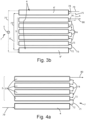
- FIGS 2 , 3b , 4b and 5b show a second embodiment of the solar system 1 according to the invention comprising two additional storage ducts 4', 4" which form said additional tank 4.
- the first circulation pump 5 can be arranged in a second return conduit 75' which connects the two additional ducts 4' and 4".
- the first hydraulic circuit 7 can have a third return conduit 75", wherein a non-return valve 6' is arranged.
- This third return conduit 75" also connects the at least two additional storage ducts 4' and 4". The function of this third return conduit 75" is to reduce the pressure losses and not force the incoming heat transfer fluid to pass only through the first circulation pump 5 which, for functional reasons, offers a high impediment to the fluid if it is not active.
- the first circulation pump 5 allows the withdrawal of the first heated heat transfer fluid, for example hot water, from the main tank 3 through the first return conduit 75 which connects the main outlet conduit 76 of the main tank 3 and the additional inlet portion 78 of the second additional storage duct 4".
- the energy is transferred from the second additional storage duct 4" to the first additional storage duct 4' through the second return conduit 75'.
- the hydraulic recirculation circuit closes via the connecting conduit 71 between the additional outlet portion 72 of the first additional storage duct 4' and the main inlet portion 73 of the main tank 3.
- the non-return valves 6 and 6' prevent hydraulic short circuits and guarantee the anti-clockwise recirculation flow, as shown in Figure 5b .
- T' 4 and T' 3 are equal to the initial temperatures of the volumes V 3 and V 4 of the two tanks 4 and 3 before the heat exchange with each other.
- the initial temperature T' 4 of the fluid contained in the additional tank 4 affects the final equilibrium temperature T" of the fluid contained in the solar system 1 during the energy transfer between the main tank 3 and the additional tank 4: the higher the initial temperature T' 4 of the fluid contained in the additional tank 4, the higher the final equilibrium temperature T". Therefore, with the repetition of storage processes, a point will be reached at which said transfer will no longer be beneficial. Therefore, when this condition is reached, the main tank 3 will continue to increase its temperature regardless of whether the recirculation circuit is activated and will potentially be able to reach the critical conditions of use (this is possible in conditions of high irradiation and particularly high external temperatures).
- the solar system 1 can therefore include a dissipator element, for example like those described in the state of the art, in order to avoid reaching this extreme condition of extraordinary use or a protection element with a safety valve that discharges hot fluid from the system automatically reintroducing cold fluid from the water grid.
- a dissipator element for example like those described in the state of the art, in order to avoid reaching this extreme condition of extraordinary use or a protection element with a safety valve that discharges hot fluid from the system automatically reintroducing cold fluid from the water grid.
- the solar system 1 is preferably designed in such a way that, in the event that the user withdraws the first heat transfer fluid every 48/72 hours, this extreme condition of extraordinary use is not likely.
- the value of the volume V 4 of the additional tank 4 can therefore be indicated in relationship to the volume V 3 of the main tank 3 via the following relationships.
- the ratio between the volume V 4 of the additional tank 4 and the volume V 3 of the main tank 3 is included in the following range of values: 0.3 ⁇ V 4 V 3 ⁇ 1.3
- the ratio between the total volume of solar system 1, V 3 + V 4 , and the collecting surface S can be included in the following range of values: 50 lit m 2 ⁇ V 3 + V 4 S ⁇ 130 lit m 2
- Figure 13 shows the flow diagram of the control strategy for the switch of the solar system 1 according to the invention between the first and second use configuration, possibly also based on time windows within which allowing the system to execute the energy transfer logic.
- the diagram shows a first option indicated with the reference XIIIa wherein the threshold temperature T s is entered by the user or installer during the installation stage.
- the system switches to the second use configuration, i.e. the energy transfer between the main tank 3 and the additional tank 4 is activated. Otherwise, the volume of the additional tank 4 does not store heated fluid and is not involved in the thermal process of the solar system 1.
- the hourly intervals selectable by the user or installer can respond to different needs, for example it is not recommended to keep the energy transfer function active close to sunset time, since it could happen that the final temperatures T" 3 and T" 4 of the fluid in tanks 3 and 4 are such that an optimal value for the DHW production cannot be guaranteed the following morning, due to the night-time cooling.
- the flow diagram of Figure 13 further shows a second option indicated with the reference XIIIb with the same options and logic as the first option XIIIa, but with the difference that the threshold temperature T s is adjusted in real time, as better explained herein below.
- T s is the threshold temperature of the fluid contained in said main tank 3, following which the system switches to the configuration of transfer of energy to the additional tank 4.
- T user means the set outlet temperature of the fluid on the user side through said outlet portion 80, set by the user or installer.
- the above set out equation has the following meaning: if I bring the volumes V 3 and V 4 into equilibrium, with the fluid in the volume V 4 of the additional tank 4 at the grid temperature T grid , the final equilibrium temperature T" must always be higher than the user temperature T user , so that the system can deliver hot water at the temperature chosen by the user.
- T s 50 ° C + 35 ° C ⁇ V 4 V 3
- T s 50 ° C + 0.625 ⁇ 50 ° C ⁇ T rete
- T s can be varied, as the grid temperature T grid has variable temperatures based on the season or the different location/climate zone.
- FIG. 6 a third embodiment of the solar system 1 according to the invention can be observed.
- the same components of the solar system 1 according to the first embodiment will be indicated with the same numerical references.
- the third embodiment differs from the first embodiment due to the different arrangement of the flow management means 5, for example said first circulation pump 5.
- This first circulation pump 5 is in fact arranged in correspondence with said connecting conduit 71, upstream from the direction of flow of the first heat transfer fluid and from the main portion of inlet 73 to the plurality of main storage ducts 31.
- This solution would be advantageous for making the first circulation pump 5 work at a lower temperature, extending its useful life as the stress to which the component is subjected is reduced. In this case, however, the pressure losses are aggravated at the time of the DHW withdrawal on the user side, therefore it is necessary to have a hydraulic pressure in the aqueduct sufficient to guarantee the DHW flow rate desired by the user.
- This embodiment differs from the previous embodiments since the activation system of the additional tank 4 is not in forced circulation, but takes place through natural circulation.
- the first hydraulic circuit 7 provides a thermostatic valve 8 which is arranged in said first return conduit 75.
- the thermostatic valve 8 prevents the passage of the first heat transfer fluid from said main outlet portion 76 of said main tank 3 to the additional inlet portion 78 of said additional tank 4.
- the thermostatic valve 8 allows the passage of the first heat transfer fluid through said first return conduit 75 and the first hydraulic circuit 7 switches into said second use configuration, putting in fluid connection the main outlet portion 76 of the main tank 3 with the additional inlet portion 78 of the additional tank 4. In this configuration a closed circuit is created wherein the first heat transfer fluid circulates in the first hydraulic circuit 7 by natural circulation.
- this solar system 1 provides collecting means 2, in particular a plurality of vacuum collecting pipes 2, inside each of which a respective duct of said plurality of main storage ducts 31 is arranged for the storage of a second heat transfer fluid or a primary heat transfer fluid, for example a 30% water and glycol solution.
- Said plurality of main storage ducts 31 are in fluid communication with each other, in particular via said plurality of further connecting conduits 74 to form the main tank 3.
- the plurality of connecting conduits 74 preferably connect said main storage ducts 31 in series. Furthermore, said main storage ducts 31 are connected with each other via a recirculation conduit 93 in such a way as to form a second hydraulic circuit 7'.
- This second hydraulic circuit 7' is a closed circuit inside which the second heat transfer fluid flows in correspondence with the collection area of the solar system 1.
- a second circulation pump 5' is arranged in said recirculation conduit 93 for activating the circulation of said second heat transfer fluid.
- the solar system 1 provides an additional tank 4 for the storage of the first heat transfer fluid or secondary fluid, in particular domestic water, arranged alongside said plurality of vacuum collecting pipes 2.
- the additional tank 4 is shielded from solar radiation and insulated.
- the additional tank 4 provides an additional inlet portion 78, in fluid connection with said inlet portion 79, and an additional outlet portion 72 of the secondary fluid.
- the outlet portion 80 of the heated secondary fluid is in fluid communication with the additional outlet portion 72 of the additional tank 4.
- Said first return conduit 75 is also provided between said additional inlet portion 78 and additional outlet 72 from said additional tank 4, to form said first hydraulic circuit 7 wherein the secondary fluid flows.
- a non-return valve 6 and said first circulation pump 5 are provided.
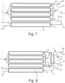
- This embodiment differs in the mode of transfer of thermal energy from the main tank 3 to the additional tank 4, which takes place by means of a heat exchanger 9.
- the heat exchange takes place between a portion of the further recirculation duct 93 of the second hydraulic circuit 7', where the primary fluid flows, and between a portion 94 of the connecting conduit 71, which corresponds to the second heat exchange portion of the first hydraulic circuit 7.
- this embodiment can provide an activation flow switch 10, arranged alongside the first hydraulic circuit 7, which activates the second circulation pump 5' in order to guarantee the forced circulation of the second heat transfer fluid inside the heat exchanger 9, during the DHW withdrawal by the user (the forced circulation of the secondary fluid is guaranteed by the grid pressure).
- the flow switch 10 is in fact activated by the circulation of the first heat transfer fluid, which is guaranteed by the grid pressure.
- the flow switch 10 acts in DHW withdrawal conditions, as it guarantees the circulation of the two fluids in the heat exchanger 9 when the user opens the taps and therefore sends the secondary fluid into circulation, moved by the grid pressure.
- the described embodiment makes it possible to reduce, even eliminate, the problems of corrosion and limescale in the plurality of main storage ducts 31 and in the plurality of further connecting conduits 74. Furthermore, this embodiment allows the use of less noble materials for producing said plurality of main storage ducts 31. The aforementioned problems are confined to the inside the heat exchanger 9 and to the additional tank 4, which are typically at lower temperatures and are also more easily replaceable.
- the first heat transfer fluid is heated following the passage through the heat exchanger 9 where the energy is transferred via heat exchange between the recirculation conduit 93 and the second heat exchange portion 94, included in the connecting conduit 71, of said second 7' and first 7 hydraulic circuits, respectively.
- the first circulation pump 5 is deactivated.
- the control unit activates the second circulation pump 5' and the first circulation pump 5 (the latter activates the circulation of the first heat transfer fluid through the first return conduit 75), thus activating the recirculation of the first heat transfer fluid in the additional tank 4 after the heat exchange in said heat exchanger 9 with the second heat transfer fluid circulating in the second hydraulic circuit 7'. Therefore, the first hydraulic circuit 7 switches into a second use configuration.
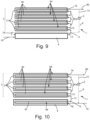
- a second heat transfer fluid is contained in a plurality of main storage ducts 31, each arranged in the respective collecting pipe of said plurality of vacuum pipes 2, and which are not in fluid connection with each other, but which form a main tank 3 of the second heat transfer fluid.
- a first heat transfer fluid is instead contained in an additional tank 4 arranged similarly to the previous embodiment but forming part of a first hydraulic circuit 7 similar to that one described for the first embodiment.
- a plurality of heat exchange conduits 90 are provided, which form said second heat exchange portion 94 of the first hydraulic circuit 7, in fluid connection with each other.
- Said heat exchange conduits 90 are arranged inside the main storage ducts 31 to allow the heat exchange with the second heat transfer fluid contained therein.
- Each heat exchange conduit 90 of said second heat exchange portion 94 is preferably a corrugated pipe.
- two use configurations are provided.
- the additional tank 4 is deactivated, as long as it is not necessary to transfer the solar energy stored in the main tank 3.
- the first heat transfer fluid flows into the first hydraulic circuit 7 from the input portion 79 to the outlet portion 80 without passing through said first return conduit 75 and wherein said additional tank 4 acts solely as an inlet passage duct for the first heat transfer fluid coming from the hydraulic grid.
- said connecting conduit 71 is provided, wherein the first heat transfer fluid flows between the additional outlet portion 72 of the additional tank 4 and the main inlet portion 73 of the main tank 3, in fluid connection with the plurality of heat exchange conduits 90 in correspondence with said second heat exchange portion 94, adapted to absorb the thermal energy from the second heat transfer fluid, contained inside the plurality of main storage ducts 31.
- the first heat transfer fluid flows between the additional outlet portion 72 of the additional tank 4 and the main inlet portion 73 of the main tank 3, in fluid connection with the plurality of heat exchange conduits 90 in correspondence with said second heat exchange portion 94, adapted to absorb the thermal energy from the second heat transfer fluid, contained inside the plurality of main storage ducts 31.
- the fluid connection between the main tank 3 and the additional tank 4 is also activated via the first return connecting conduit 75 of said first hydraulic circuit 7, via the activation of flow management means, for example said first circulation pump 5, which were deactivated in said first use configuration.
- flow management means for example said first circulation pump 5, which were deactivated in said first use configuration.
- the first hydraulic circuit 7 becomes a closed circuit wherein the first heat transfer fluid passing through the first return conduit 75, which acts as a recirculation conduit, allows the circulation of the first heat transfer fluid between the additional tank 4 and the plurality of heat exchange conduits 90 inserted in the main tank 3, thus also cooling the second heat transfer fluid contained in the main tank 3, de facto allowing the system to operate at a lower average temperature, if temperature conditions are reached such that said solar system 1 risks overheating.
- This embodiment compared to the fifth one, allows the plurality of heat exchange conduits 90 to be integrated, in fluid connection with each other, inside said plurality of main storage ducts 31 of said main tank 3 wherein the second heat transfer fluid, thus the solar system 1 is more compact.
- the presence of the second primary circulation pump 5' and the flow switch 10 described previously is not necessary.
- the length of the plurality of heat exchange conduits 90 is limited by the volume of the main storage ducts 31, therefore the exchange area between the second heat transfer fluid and the first heat transfer fluid is more constrained.
- the second heat transfer fluid carries out the heat exchange in natural convection; therefore, the heat exchange efficiency is also lower than in the case wherein a circulator, dedicated to the second heat transfer fluid, is adopted.
- a seventh embodiment of the solar system 1 according to the invention can be observed, wherein inside the plurality of main storage conduits 31 and inside the additional tank 4, a second heat transfer fluid is present, in particular a primary fluid as previously described.
- a second heat transfer fluid is present, in particular a primary fluid as previously described.
- a second heat transfer fluid is contained in a plurality of main storage ducts 31, each arranged in the respective collecting pipe 2 and not in fluid connection with each other, but forming a main tank 3 of the second heat transfer fluid.
- a second heat transfer fluid is also contained in an additional tank 4, not in fluid connection with said plurality of main storage ducts 31.
- a first heat exchange portion 94' of the first hydraulic circuit 7 is provided, inside said additional tank 4, comprising a second heat exchange conduit 91 placed inside said additional tank 4 wherein a first heat transfer fluid, introduced via an additional inlet portion 78, flows in fluid connection with the inlet portion 79 of the first heat transfer fluid from the hydraulic grid and with a first return conduit 75, or recirculation branch 75.
- This second heat exchange conduit 91 is in fluid communication with said connecting conduit 71 in correspondence with said additional outlet portion 72.
- a second heat exchange portion 94 of the first hydraulic circuit 7 is provided, coinciding with the main tank 3, with a plurality of heat exchange conduits 90, arranged inside said plurality of main storage conduits 31 wherein the first heat transfer fluid flows, introduced through a main inlet portion 73, in fluid connection with said connecting conduit 71 from the first heat exchange portion 94', and a main outlet conduit 76 in fluid connection with the outlet portion 80 and with the first return conduit 75.
- Said plurality of heat exchange conduits 90 is preferably composed of a plurality of corrugated pipes, connected in series or in parallel via the plurality of further connecting conduits 74.
- the first return conduit 75 is adapted to allow the recirculation of the first heat transfer fluid between the main outlet portion 76 and the additional inlet portion 78.
- a first circulation pump 5 and a non-return valve 6 are provided in correspondence with the first return conduit 75.
- the additional tank 4 is deactivated, as long as it is not necessary to transfer the solar energy stored in the main tank 3.
- the first heat transfer fluid first flows into the first hydraulic circuit 7 in correspondence with the first heat exchange portion 94' and then into the plurality of heat exchange conduits 90, from the inlet portion 79 to the outlet portion 80 without passing through said first return conduit 75.
- the second heat transfer fluid contained in the additional tank 4 has a temperature higher than the grid temperature T grid
- the first heat exchange area 94' acts as a pre-heating area for the first heat transfer fluid introduced into system 1.
- the first return conduit 75 is activated by the first circulation pump 5, therefore the first heat transfer fluid is set in motion in the closed circuit operating between the portions 76, 78, 72 and 73 of the first hydraulic circuit 7.
- the excess energy in the plurality of said main storage ducts 31 is transferred to the additional tank 4 by means of the plurality of heat exchange conduits 90 and the second heat exchange conduit 91.
- the solution of Figure 10 allows the use of a second low pressure heat transfer fluid in the additional tank 4, therefore the additional tank 4 can be made of a generic shape and therefore be more easily integrated into the compact system.
- the use of a plurality of heat exchange conduits 90 and of the second heat exchange conduit 91 introduces heat exchange efficiency factors, therefore the second heat transfer fluid must always be at a temperature a few degrees centigrade higher than the first heat transfer fluid in each heat exchange area. This implies that at the end of the withdrawal on the user side it is necessary to leave the second heat transfer fluid at a temperature higher than that one resulting in the systems wherein the first heat transfer fluid is present inside the tanks.
- the invention makes it possible to use the excess incident solar energy stored in the system, at the same time preventing it from reaching an extreme use temperature value, and to operate at a lower average temperature, increasing efficiency and decreasing dissipation towards the external environment.
- the invention advantageously makes it possible to obtain a V/S volume-to-collection surface ratio that is dynamic over time, variable on the basis of the weather and/or use conditions, for example that can be increased in overtemperature conditions and decreased in conditions of low solar irradiation.
- the invention presents a control strategy, based on the calculation of a T s beyond which a dedicated circuit activates/deactivates the energy transfer between the main tank and the additional tank, allowing an efficient use of the system even in conditions of an excessive solar radiation, storing the excess temperature of the fluid, or in conditions of poor solar radiation, preventing the heat exchange between the main tank and the additional one and allowing the solar system to heat the fluid sufficiently to the design conditions.
- the invention in some of its embodiments it provides the use of a primary fluid inside said storage ducts and/or inside the additional storage tank, allowing the use of less noble materials for manufacturing the ducts.
- this advantageously makes it possible to use all the solar energy for heating the heat transfer fluid contained in the main storage, in direct thermal contact with the absorber element or collecting means, and then in a sequential manner for heating the heat transfer fluid contained in the other additional storages. This makes it possible to "stratify" the thermal energy and make hot water available at the design temperature first.
Landscapes
- Engineering & Computer Science (AREA)
- Physics & Mathematics (AREA)
- Life Sciences & Earth Sciences (AREA)
- Sustainable Development (AREA)
- Sustainable Energy (AREA)
- Thermal Sciences (AREA)
- Chemical & Material Sciences (AREA)
- Combustion & Propulsion (AREA)
- Mechanical Engineering (AREA)
- General Engineering & Computer Science (AREA)
- Heat-Pump Type And Storage Water Heaters (AREA)
Abstract
Description
- The present invention concerns a compact solar system.
- More precisely, the present invention concerns a compact solar system comprising a hydraulic circuit adapted to activate or deactivate an area of thermal energy storage.
- In the state of the art, solar systems for the production of domestic hot water (DHW) are known, which are divided into two macro-families: forced circulation systems and natural circulation systems. The former provide solar collectors (hereinafter also called just collectors) connected, via a hydraulic circuit with circulator, to an insulated energy storage located in a technical room. In the latter, the energy storage element is generally placed near the collector and the energy collected by the collector is transferred on site to the storage, by natural circulation.
- The latter systems are in turn divided into systems with the storage separated from the collector and systems with an integrated storage (called in English Integrated Collector Storage or more briefly ICS or compact solar systems), used to reduce the architectural impact, in order to try to limit the size of the solar system as much as possible.
- In these systems, solar energy is collected by collecting surfaces (S), covered by highly selective material which transmit part of this energy to an energy storage volume (V) containing a primary heat transfer fluid, for example technical water, or directly a secondary fluid, such as domestic hot water (DHW). De facto, the system receives solar energy in the form of light (electromagnetic) energy and stores part of this energy in the form of thermal energy, increasing the temperature of the fluid stored in the storage tank; generally the outer surface of the storage itself actively participates in the solar energy absorption stage, or in any case the collector and the storage are integrated and are not clearly distinguishable from the outside, all forming a compact system.
- The state of the art of ICS systems provides for the division into two families of systems based on the method of control of heat dispersions towards the environment: in the former, heat dispersions are reduced by using a glass cover (for example in
patent documents EP 2 746 692 A1 ,EP 2 924 364 B1WO 2019/123508 A1 andWO 2018/055648 A1 . - In most of the state-of-the-art ICS compact systems, for safety reasons of the components (such as circulators, gaskets, etc.), and given the technical operating limits of the mixing valve of the downstream sanitary system and for avoiding excessive pressures or generation of steam by lamination at ambient pressure, the upper limit of the temperature of the storage fluid is fixed at approximately 90° - 99°C. Beyond this limit it is necessary to adopt a protection system. Commonly, this protection system consists of dissipating the thermal energy generated, originating from the collection of solar radiations, when the storage temperature reaches its limit values.
- Some examples of ICS systems with this safety system, adapted to dissipate the energy stored when the temperature reaches its limit values, are described in the following patent documents:
-
WO 2019/123508 A1 , wherein it is described a system which in extreme conditions puts the superheated fluid into forced circulation through a circuit obtained on an aluminium frame, suitably finned in such a way as to dissipate heat towards the environment, and -
WO 2018/055648 A1 , wherein the overpressure originated from the expansion of the superheated fluid as the temperature increases is used to trigger a thermomechanical kinematic mechanism via a hydraulic piston, which leads to the shielding of the collecting surface, thus avoiding the entry of energy solar into the system, which is reflected, and causing a cooling of the primary superheated fluid. - Generally, in known solar systems, the collection of solar energy takes place in the form of light (electromagnetic) energy converted into thermal energy, increasing the temperature of the fluid stored in the storage and of the system components. In periods of more favourable weather conditions, it is possible that the system reaches overheating conditions due to excessive stored thermal energy, which leads to a possible malfunction of the solar system components and therefore of the system itself. State-of-the-art safety systems are adapted to prevent the reaching of operating extreme temperatures. They have the objective of dissipating the excess energy if a DHW withdrawal is not made on the user side (in fact, during the withdrawal, water at the grid temperature, for example at 15-20°C, is introduced into the system, cooling it accordingly), thus preserving the integrity of the system.
- Although these safety systems prevent the system from reaching critical temperature values, they do not allow the excess solar energy incident on the system to be used, as this is dispersed and released into the surrounding environment.
- The process of heating a fluid using compact solar systems also depends on the nature and volume of the fluid stored in the system. In particular, for most cases where the working fluid is water, the ratio between the volume of the stored fluid (V) and the collecting surface (S), here indicated as V/S, represents a critical factor for the efficiency of such systems.
- In fact, the value of the ratio between storage volume and collection surface, referred to as V/S, must fall within an optimal range, which however can vary based on the conditions of use and weather conditions. In particular, if the V/S value is too high, the solar energy may not be sufficient to heat the system and therefore to guarantee the withdrawal of DHW at the minimum design temperature (typically the system must deliver hot water at a temperature not lower than 40°C - 50°C). On the contrary, if the V/S value is too low, the heating process leads to frequent overtemperature conditions; this is because the collected solar energy corresponds to a low storage volume, therefore, there is a greater risk of increasing the fluid temperature to unacceptable values. Furthermore, due to the extreme variability and unpredictability of solar energy, it is not possible a priori (during the design stage) to choose a V/S fixed value that avoids such critical conditions, especially because an ideal system must have a V/S value that allows the availability of domestic hot water even with limited irradiation windows or in conditions of poor irradiation.
- The aim of the present invention is to maximise all the solar energy incident on the system, by reducing the dissipation of the incident energy to a minimum, without compromising the performance of the system throughout the year, under both more unfavourable weather conditions and favourable weather conditions.
- Furthermore, an aim of the present invention is to allow the compact solar system to store excess energy, without reaching the maximum operating temperature values.
- Another aim of the present invention is to allow a rapid heating of the compact solar system under any condition of irradiation and user profile.
- Again, an aim of the present invention is to operate the system, as far as possible, at an average temperature of the stored fluid lower than 75°C, which allows the efficiency of the system itself to be increased (less dispersions towards the environment), to limit the thermal stress of the system components and reduce the limescale formation processes.
- An object of the present invention is a compact solar system for heating a first heat transfer fluid; said solar system includes an external frame, inside which the following elements are contained: a main tank for containing a heat transfer fluid; collecting means for collecting the incident solar radiation, which, being in heat exchange with said main tank, make it possible to transfer the collected thermal energy to the heat transfer fluid stored in the main tank; and a first hydraulic circuit for the circulation of the first heat transfer fluid, which includes an inlet portion for the inlet of the first heat transfer fluid and an outlet portion for the outlet of the first heat transfer fluid.
- Furthermore, the solar system is characterised in that it includes an additional tank inside the frame to contain a heat transfer fluid, thermally isolated from the collecting means, and in that the volumetric ratio between the volume of the additional tank and the volume of the main tank is defined by the following relationship:

- Furthermore, the first hydraulic circuit provides a first heat exchange portion, in heat exchange with the heat transfer fluid contained in the additional tank, and a second heat exchange portion in heat exchange with the heat transfer fluid contained in the main tank.
- The first and second heat exchange portions are in fluid connection with each other via a connecting conduit and a first return conduit.
- Furthermore, the compact solar system is characterised in that it provides flow adjusting means, arranged in the first hydraulic circuit, to allow the circulation of the first heat transfer fluid from the second heat exchange portion to the first heat exchange portion through the first return conduit, when a threshold temperature of a heat transfer fluid contained in the main tank is reached.
- Possibly according to the invention, the first heat exchange portion of the first hydraulic circuit can be the additional tank. The additional tank can therefore be adapted to contain the first heat transfer fluid, and be in fluid connection with the connecting conduit and with the first return conduit of the first hydraulic circuit and with the inlet portion.
- Possibly according to the invention, the second heat exchange portion of the first hydraulic circuit can be the main tank, which can be adapted to contain the first heat transfer fluid and be in fluid connection with the connecting conduit and the first return conduit of the first hydraulic circuit and with the outlet portion.
- In particular, according to the invention, the main tank can contain a second heat transfer fluid, not in fluid connection with the first heat transfer fluid.
- Alternatively, according to the invention, the solar system can include a second hydraulic circuit for the circulation of the second heat transfer fluid. The second hydraulic circuit can be a closed circuit composed of the main tank and a recirculation conduit. Furthermore, the solar system can include a heat exchanger, wherein the recirculation conduit of the second hydraulic circuit and the second heat exchange portion of the first hydraulic circuit can be arranged, in heat exchange with each other.
- Again, according to the invention, the solar system can include a second circulation pump arranged in the second hydraulic circuit, to be able to activate the circulation of said second heat transfer fluid in said second hydraulic circuit. Furthermore, it can include means for detecting the circulation of the first heat transfer fluid, in particular a flow switch, in the first hydraulic circuit. Said detecting means can be in connection with the second circulation pump and the solar system can furthermore be configured to activate/deactivate said second circulation pump on the basis of the values detected by the detecting means.
- Preferably according to the invention, the second heat exchange portion of the first hydraulic circuit can be arranged inside the main tank.
- In particular, according to the invention, the additional tank can contain a second heat transfer fluid, not in fluid connection with the first heat transfer fluid, wherein the first heat exchange portion of the first hydraulic circuit can be arranged inside the additional tank itself.
- Still according to the invention, the flow adjusting means, arranged in the first hydraulic circuit, can be a first circulation pump and a non-return valve, wherein said non-return valve can be arranged on the first return conduit between the two heat exchange portions.
- Again, according to the invention, the first circulation pump can be arranged on one of the connecting or return conduits, between said two (first and second) heat exchange portions.
- Alternatively, according to the invention, the flow adjusting means can be arranged in the first hydraulic circuit and can be a thermostatic valve or an electrovalve, arranged in the first return conduit, between said two heat exchange portions.
- Furthermore, according to the invention, the main tank can include a plurality of main storage ducts in fluid connection with each other.
- More particularly according to the invention, the second heat exchange portion can include a plurality of heat exchange conduits, in fluid connection with each other; each of which can be inserted into a respective main storage duct of the main tank.
- Furthermore, according to the invention, the collecting means of the solar system can be a plurality of pipes having an outer vacuum gap.
- In particular, according to the invention, each main storage duct of the main tank can be inserted into a respective pipe having an outer vacuum gap.
- Preferably according to the invention, the additional tank can include at least two additional storage ducts in fluid connection with each other.
- In particular, according to the invention, the ratio between the sum of the volumes of the main and additional tanks and the surface of the collecting means is defined by the following relationship:

- Further according to the invention, the solar system can include a control unit connected to the flow adjusting means arranged in the first hydraulic circuit. The control unit can be configured to act on the flow adjusting means on the basis of the temperature of the heat transfer fluid contained in the main tank, when said threshold temperature is reached.
- In particular, the threshold temperature can be defined by the following formula:

- wherein Tuser is equal to the temperature of the first heat transfer fluid coming out from the outlet portion,
- wherein Tgrid is equal to the temperature of the first heat transfer fluid coming in from the inlet portion, and
- wherein V3 and V4 are the main and additional tank volumes, respectively.
- Preferably according to the invention, the solar system can include temperature detecting means, arranged in said main tank, for detecting the temperature of the heat transfer fluid contained therein.
- Furthermore, according to the invention, the flow adjusting means can include a thermal switch, for detecting the temperature of the heat transfer fluid contained in the main tank, and a first circulation pump electrically connected to said thermal switch. Furthermore, said first circulation pump can be arranged in the first hydraulic circuit and the thermal switch can be arranged in the main tank, in direct or indirect contact with the heat transfer fluid contained therein.
- More specifically, according to the invention, the temperature detecting means or the thermal switch can be inserted into a possible thermowell.
- Finally, according to the invention, the solar system can be adapted to assume a first use configuration, wherein the first heat transfer fluid can be adapted to flow into said first hydraulic circuit from the inlet portion to the outlet portion, passing through the first and the second heat exchange portion passing only through the connecting conduit. Furthermore, the solar system can assume a second use configuration, wherein the first heat transfer fluid can circulate in the first hydraulic circuit between the first and second heat exchange areas, passing through both the connecting conduit and the first return conduit. Furthermore, during use, the solar system can assume said second use configuration when the temperature of the heat transfer fluid contained in the main tank exceeds said threshold temperature.
- The invention will now be described for illustrative but non-limiting purposes, with particular reference to the drawings of the attached figures, wherein:
-
Figure 1a shows a perspective view of the solar system according to the invention, in a first embodiment; -
Figure 1b shows a perspective cutaway view of the solar system ofFigure 1a ; -
Figure 1c shows an exploded perspective view of the solar system ofFigure 1a ; -
Figure 1d shows a top view of some components of the solar system ofFigure 1c ; -
Figure 2 shows a top view of some components of a solar system according to the invention, in a second embodiment; -
Figure 3a shows a schematic view of the hydraulic circuit of the solar system ofFigure 1a ; -
Figure 3b shows a schematic view of the hydraulic circuit of the solar system ofFigure 2 ; -
Figure 4a shows a schematic view of the hydraulic circuit ofFigure 3a , in a first use configuration during the withdrawal of the heated secondary fluid; -
Figure 4b shows a schematic view of the hydraulic circuit ofFigure 3b , in a first use configuration during the withdrawal of the heated secondary fluid; -
Figure 5a shows a schematic view of the hydraulic circuit ofFigure 3a , during the second use configuration wherein the energy transfer takes place between the main tank and the additional tank; -
Figure 5b shows a schematic view of the hydraulic circuit ofFigure 3b , during the second use configuration wherein the energy transfer takes place between the main tank and the additional tank; -
Figure 6 shows a schematic view of the hydraulic circuit of the solar system according to the invention in a third embodiment; -
Figure 7 shows a schematic view of the hydraulic circuit of the solar system according to the invention in a fourth embodiment; -
Figure 8 shows a schematic view of the hydraulic circuits of the solar system according to the invention in a fifth embodiment; -
Figure 9 shows a schematic view of the hydraulic circuits of the solar system according to the invention in a sixth embodiment; -
Figure 10 shows a schematic view of the hydraulic circuits of the solar system according to the invention in a seventh embodiment; -
Figure 11a shows a schematic view of the solar system ofFigure 3a associated with a first control system; -
Figure 11b shows a schematic view of the solar system ofFigure 3a associated with a second control system; -
Figure 11c shows a schematic view of the solar system ofFigure 3a associated with a third control system; -
Figure 12 shows a sectional view along the XII-XII' section plane of the solar system ofFigure 11a ; -
Figure 13 shows the flow diagram of the operating logic of the hydraulic circuit of the solar system according to the invention; -
Figure 14 shows a graph representing the variation in threshold temperature as the ratio between the volume of the additional tank and the volume of the main tank of the solar system according to the invention varies, and as the water grid temperature varies; -
Figure 15 shows a graph representing the variation of the threshold temperature of the solar system according to the invention as the temperature of the water grid varies for different values of the ratio between the volume of the additional tank and the volume of the main tank; and -
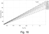
Figure 16 shows a graph representing the variation of the threshold temperature as the ratio between the volume of the additional tank and the volume of the main tank of the solar system according to the invention varies, for different values of the water grid temperature. - As previously mentioned, the process of heating a fluid by compact solar systems depends on the ratio between the volume of the stored fluid (V) and the collecting surface (S).
- The importance of the V/S ratio can be better understood with a numerical example, wherein the energy transferred to the volume of stored fluid can be expressed in the form:

- Where:
- G [J/m2] indicates the amount of incident solar energy per surface unit,
- S [m2] represents the collecting surface of the compact solar system, η is the solar energy collection efficiency of the solar system,
- V [m3] is the stored fluid volume,
- ρ [kg/m3] indicates the stored fluid density,
- c [J/kg*K] represents the specific heat of the stored fluid, and
- ΔT [K] is the temperature difference of the stored fluid between the beginning and the end of the heating process of such fluid.
- After a simple mathematical step, it can be noted that, by increasing the solar energy G, with the same V/S ratio, the value of ΔT and therefore the temperature difference of the stored fluid will increase.

- If, however, an increase in G also corresponds to an increase in V/S, it can be seen from the equation that the ΔT value will increase less than in the previous case.
- Below are some numerical examples having the aim of calculating the actual ΔT values, using specific fixed G, V/S, η values of a solar system adapted to simulate true environmental and use conditions (
grid temperature 15°C and minimum final DHW outlet temperature in the range 40°C - 50°C). - "Blue sky" winter day (in Italian "cielo blu", name for a day of favourable solar irradiation):
- G = 17 MJ/m2
- V/S = 40 l/m2
- η = 0.6
- ΔT = 61°C (
final temperature 76°C) - "Blue sky" summer day:
- G = 27 MJ/m2
- V/S = 40 l/m2
- η = 0.6
- ΔT = 97°C (final temperature 112°C)
- Therefore, in summer the system in a single day of solar energy storage can be in overtemperature conditions.
- If, however, in summer a solar system having a higher V/S value equal to, for example, 60 l/m2 is taken into consideration,
- "Blue sky" summer day:
- G = 27 MJ/m2
- V/S = 60 l/m2
- η = 0.6
- ΔT = 65°C (
final temperature 80°C) - In this case, reaching overtemperature conditions is avoided and at the same time all the daily solar energy is stored.
- Imagining adopting only the same solar system of V/S value = 60 l/m2, we are considering a day with little irradiance, technically known as "grey sky day" (in Italian "giornata di cielo grigio"). The solar energy values can also be halved, so the calculation becomes:
- "Grey sky" winter day:
- G_inv = 8 MJ/m2
- V/S = 60 l/m2
- η = 0.6
- ΔT = 19°C (final temperature 34°C)
- That is, the design DHW temperature conditions are not reached.
- Instead, if a solar system with a V/S value = 40 l/m2 is adopted again, we obtain:
Grey sky winter day - G_inv = 8 MJ/m2
- V/S = 40 l/m2
- η = 0.6
- ΔT = 29°C (final temperature 44°C)
- Therefore, in this case a temperature is reached that falls within the design range of 40 - 50°.
- Moreover, if a secondary circuit for heating a secondary fluid by heat exchange with a primary fluid (for example by a heat exchanger) is used, it is important that the solar system has a more conservative V/S value, because it is necessary to bring the primary storage to high temperature to allow an optimal primary/secondary exchange. In other words, having a primary fluid at 45 - 50°C is not sufficient to guarantee a heat exchange with the secondary circuit such as to bring it to design DHW conditions of 40°C - 50°C, unless using a heat exchanger having a high exchange surface, which would make the objective of creating a compact system difficult and would also be anti-economic.
- In the context of systems wherein there is a constant transfer of energy from the collection area to the storage area, the solar system according to the present invention provides the possibility of having a dynamic V/S ratio value over time, therefore variable depending on weather conditions.
- In
Figures 1a - 1d and3a ,4a and5a a solar system according to the invention is shown, in a first embodiment, indicated with thenumerical reference 1. - The
solar system 1 according to the invention is of the compact type, as previously described, and is adapted to heat a first heat transfer fluid, in particular a secondary fluid, for example domestic hot water (DHW). Thesolar system 1 includes anexternal frame 200, inside which the following elements are contained, described herein below. - A
main tank 3 necessary to contain a heat transfer fluid, collecting means 2 for collecting the solar radiation incident on them, a firsthydraulic circuit 7 for the circulation of the first heat transfer fluid, and anadditional tank 4 for containing a heat transfer fluid. - In the present embodiment, the
main tank 3 and theadditional tank 4 are adapted to contain the same heat transfer fluid, in particular said first heat transfer fluid. In other embodiments, as will be seen below, a second heat transfer fluid can be provided, possibly contained in one of the two tanks. - The collecting means 2 are in heat exchange with the
main tank 3 in order to transfer the collected thermal energy to the heat transfer fluid contained in themain tank 3. The firsthydraulic circuit 7 in turn includes aninlet portion 79 for the inlet of the first incoming heat transfer fluid and anoutlet portion 80 for the outlet of the first outgoing heat transfer fluid on the user side. - Furthermore, the
additional tank 4 is thermally insulated from the collecting means 2. Themain tank 3 and theadditional tank 4 are such that the volumetric ratio between their respective volumes V3 and V4 is defined by the following relationship:
- Moreover, the first
hydraulic circuit 7 provides a firstheat exchange portion 4, which is in heat exchange with the heat transfer fluid contained in saidadditional tank 4, and a secondheat exchange portion 3, which instead is in heat exchange with the heat transfer fluid contained in themain tank 3. Said first 4, 94' and second 3, 94 heat exchange portions are in fluid connection with each other via a connectingconduit 71 and afirst return conduit 75. In the specific embodiment, the two heat exchange portions coincide respectively with theadditional tank 4 and themain tank 3, as both are adapted to contain the same first heat transfer fluid which, by circulating and mixing between the two tanks at different temperatures, act as heat exchange areas. - The compact
solar system 1 according to the invention also provides flow adjusting means 5, 6 arranged in the firsthydraulic circuit 7, used in order to allow the circulation of the first heat transfer fluid from the secondheat exchange portion 3 to the firstheat exchange portion 4 through saidfirst return conduit 75, when a threshold temperature Ts of a heat transfer fluid contained in saidmain tank 3 is reached. - Preferably, said
solar system 1 can be adapted to assume a first use configuration wherein the first heat transfer fluid is adapted to flow into said firsthydraulic circuit 7 from saidinlet portion 79 to saidoutlet portion 80 through said first 4 and second 3 heat exchange portions passing only through said connectingconduit 71, and a second use configuration wherein the first heat transfer fluid circulates into said firsthydraulic circuit 7 between said first 4 and second 3 heat exchange areas passing through both said connectingconduit 71 andfirst return conduit 75. Again, during use, saidsolar system 1 assumes said second use configuration when the temperature T3 of the heat transfer fluid contained in themain tank 3 exceeds said threshold temperature Ts. - In the embodiments described herein the collecting means are a plurality of
vacuum collecting pipes 2 having an outer gap. In other embodiments, the collecting means can be of a different type, for example themain tank 3 can be directly painted with a highly selective material and protected by a non-vacuum glass cover, or the collecting means can be absorbers consisting of a sheet of metallic material coated by a highly selective material, which is placed in heat exchange with themain tank 3. - Furthermore, in the present embodiment the
main tank 3 includes a plurality ofmain storage ducts 31, in fluid connection with each other, for the storage of the secondary fluid to be heated. - Again, in the present embodiment, a corresponding
main storage duct 31 is preferably arranged inside each collectingvacuum pipe 2 with an outer gap. Said plurality ofmain storage ducts 31 are in fluid connection with each other, via a plurality of further connectingconduits 74, to form themain tank 3. - Furthermore, in the present embodiment the
additional tank 4, which is in fluid connection with saidmain tank 3, is arranged adjacent thereto, preferably in the lower portion of thesolar system 1. - Said
additional tank 4 can include one or more additional storage ducts in fluid connection with each other or a single duct, as shown for the first embodiment. Saidadditional tank 4 is shielded from solar radiation by a suitable opaque surface (which can also be theframe 200 of thesystem 1 itself) and is suitably insulated to reduce heat dissipation towards the environment external to thetank 4 itself. Saidadditional tank 4 is separated from themain tank 3 and the separation space is suitably insulated. - The
additional tank 4 can be arranged in the upper part of thesolar system 1, in the lower part of thesolar system 1 or in any central area of thesolar system 1, both in a horizontal position and in a vertical position if it is elongated in shape. - Furthermore, the
additional tank 4 can have a cylindrical shape but also any shape that ensures a structural resistance to the hydraulic pressure of the contained fluid. - Furthermore, the material of the
additional tank 4 can be stainless steel but also any material that is compatible with the temperatures and intended use of the contained fluid. - In the present embodiment, the first
hydraulic circuit 7 includes saidadditional tank 4, said plurality ofmain storage ducts 31 and said plurality of further connectingconduits 74. Furthermore, said firsthydraulic circuit 7 provides a connectingconduit 71 for the fluid connection of theadditional tank 4, in correspondence with anadditional outlet portion 72 of saidadditional tank 4, with saidmain tank 3, in particular with at least one duct of said plurality ofmain storage ducts 31, in correspondence with amain inlet portion 73 of saidmain tank 3, in particular of a duct of said plurality ofmain storage ducts 31. - Furthermore, said first
hydraulic circuit 7 includes afirst return conduit 75 for the fluid connection of themain tank 3, in correspondence with itsmain outlet portion 76, with theadditional inlet portion 78 of saidadditional tank 4. Preferably, in the described embodiment, in correspondence with saidfirst return conduit 75 there is arranged afirst circulation pump 5 adapted to move the first heat transfer fluid from saidmain tank 3 to saidadditional tank 4. Saidfirst circulation pump 5 can be connected to a control unit (as shown for the first control system inFigure 11a ). Alternatively, a different control system can be provided wherein thefirst circulation pump 5 is connected to a thermal switch which activates it depending on the temperature value detected by the switch itself (as shown inFigure 11b ). - Furthermore, said
first return conduit 75 in turn comprises anon-return valve 6, arranged between said twoheat exchange portions main outlet portion 76 of themain tank 3 and saidadditional inlet portion 78 of theadditional tank 4. - During use, when the first heat transfer fluid is withdrawn from the
outlet portion 80, the first heat transfer fluid is simultaneously introduced through theinlet portion 79 at the same flow rate. - According to the invention in a first use configuration (shown in
Figure 4a ), as long as it is not necessary to transfer the stored solar energy from themain tank 3 to theadditional tank 4, the latter will not participate in the process of storing the incident solar energy. In other words, the first heat transfer fluid flows into the firsthydraulic circuit 7 from theinlet portion 79 to theoutlet portion 80 without passing through thefirst return conduit 75 between themain storage 3 and the additional one 4 (which inFigure 4a has not been shown as it is not operational, like the first circulation pump 5), therefore the energy present in themain tank 3 is transferred only to the user downstream of theoutlet portion 80. In this condition, the solar energy, transferred to the heated fluid, is stored only in themain tank 3 exposed to solar radiation. In this condition, theadditional tank 4 acts solely as an inlet passage conduit for the first heat transfer fluid coming from the hydraulic grid. - Again, according to the invention, the
solar system 1 is able to assume a second use configuration (shown inFigure 5a ), if temperature conditions are reached such that saidsolar system 1 risks overheating. Thanks to theadditional tank 4 and said first dedicatedhydraulic circuit 7, in particular thanks to thefirst return conduit 75, it is possible to also make theadditional tank 4 participate in the storage of solar energy and therefore to increase or decrease the value of the V/S ratio of thesolar system 1 according to the invention on the basis of the weather conditions, since the collected solar energy can be redistributed not only in the volume V3 of themain tank 3, but also in the volume V4 of theadditional tank 4. - When the extreme conditions of use are reached, i.e. when a threshold temperature Ts of the fluid placed inside the
main tank 3 is reached, the fluid connection between themain tank 3 and theadditional tank 4 is activated also via thefirst return conduit 75 of said firsthydraulic circuit 7, (as shown inFigure 5a ) by activation of flow management means 5, for example saidfirst circulation pump 5, which were deactivated in said first use configuration. By activating thefirst circulation pump 5, the first heat transfer fluid flows between saidadditional inlet portion 78 of saidadditional tank 4 and saidmain outlet portion 76 of saidmain tank 3, passing through saidfirst return conduit 75. This therefore allows the energy transfer between the volumes V3 and V4 of saidtanks hydraulic circuit 7 becomes a closed circuit wherein the first heat transfer fluid by passing through thefirst return conduit 75, which acts as a recirculation conduit, allows the circulation of the first heat transfer fluid between the twotanks additional tank 4. - This transfer can take place via passive control, for example by opening and closing of electromechanical elements, or active control, for example via electronics and control logic.
- It may also happen that, during the energy transfer, the user needs DHW, therefore grid water is introduced through the
inlet portion 79 and hot water is delivered through theoutlet portion 80. This can also occur in conjunction with the activation of thefirst circulation pump 5 and therefore in conjunction with the energy transfer, without compromising the transfer itself or the quality of the DHW delivered on the user side. -
Figures 11a, 11b and11c show three variants of the embodiment ofFigure 3a associated with alternative control systems for describing some principles of activation of the circulation conduits in the recirculation branches, in particular in thefirst return conduit 75, arranged for transferring energy between themain tank 3 and theadditional tank 4. - In particular,
Figure 11a shows a schematic showing a first control system for controlling thefirst circulation pump 5 via a control unit orcontrol panel 100. Thecontrol unit 100 has means for detecting thetemperature 102, in particular atemperature sensor 102, which detect the value of the temperature T3 of the fluid contained in themain tank 3, in particular in one of the ducts of said plurality ofmain storage ducts 31, which is compared with the value of the threshold temperature Ts. The comparison can be made via threshold/hysteresis logic or via more complex logics, such as PID, PD, PI. Thetemperature sensor 102 can be either in direct or indirect contact with the fluid contained in themain tank 3 or more simply in indirect contact with this fluid, for example by placing it in a thermowell 101 (as shown inFigure 12 ) or in contact with the material of which the ducts of said plurality ofmain storage ducts 31 are made. Therefore, thecontrol unit 100 decides whether to activate the second use configuration, by electrically powering thefirst circulation pump 5 or not. Thefirst circulation pump 5 therefore guarantees the hydraulic head useful for circulating the fluid (by putting the fluid under pressure) through thenon-return valve 6 and overcoming pressure losses throughout the recirculation circuit. - In
Figure 11b , alternatively to the control unit ofFigure 11a , there is a second control system comprising athermal switch 103 which detects the temperature T3 of the fluid contained in themain tank 3 or more simply in indirect contact with this fluid, for example by placing it in athermowell 101, in particular in the plurality ofmain storage ducts 31, and on the basis of this value thethermal switch 103 closes or not the electrical power circuit of thefirst circulation pump 5. Thethermal switch 103 is preferably arranged in indirect contact with the fluid contained in the plurality ofmain storage ducts 31, for example by inserting it into a thermowell 101 (as shown inFigure 12 ) or in contact with the material of which the ducts of said plurality ofmain storage ducts 31 are made. - Furthermore,
Figure 11c shows an alternative schematic of the system including a third control system, wherein in thefirst return conduit 75 there is anelectrovalve 6". The latter, if de-powered, is able to stop the circulation of the heat transfer fluid inside saidfirst return conduit 75, while, when powered, theelectrovalve 6" allows the passage of fluid. Therefore, similarly to the control of thefirst circulation pump 5 of the solution ofFigure 11a , thecontrol unit 100 can electrically power or not power theelectrovalve 6" and allow the transfer of energy between themain tank 3 and theadditional tank 4 by means of a natural circulation motion of the fluid. - The described solutions have no limitations on the methods of controlling the energy transfer between the
main tank 3 and theadditional tank 4, any alternative solutions that have the same functional purpose are considered to be equivalent. - In cases where there is the active control, the threshold temperature Ts can be set by the installer or the customer by means of the electronic device supplied with the system, i.e. a control device that allows the adjustment of the system operating parameters and the principle of operation of the
additional tank 4. In any case, a set of recommended default values can be indicated by the manufacturer. - In cases where there is the passive control, components are chosen that intervene at a specific threshold temperature Ts.
- Preferably the threshold temperature Ts is between 50°C and 85°C.
- In further embodiments, the volume of the additional tank can be composed of a plurality of storage ducts that can be activated in cascade, for example the transfer to a first additional tank can be activated when the threshold temperature Ts in the main tank is reached, in turn the transfer to a second additional tank can be activated once the threshold temperature has been reached in the first additional storage and so on. Of course, the choice of the number of additional storage ducts depends on the balance between benefits and costs.
-
Figures 2 ,3b ,4b and5b show a second embodiment of thesolar system 1 according to the invention comprising twoadditional storage ducts 4', 4" which form saidadditional tank 4. - This makes it possible to obtain a dimensional compactness. In this case, the
first circulation pump 5 can be arranged in a second return conduit 75' which connects the twoadditional ducts 4' and 4". In this embodiment, the firsthydraulic circuit 7 can have athird return conduit 75", wherein a non-return valve 6' is arranged. Thisthird return conduit 75" also connects the at least twoadditional storage ducts 4' and 4". The function of thisthird return conduit 75" is to reduce the pressure losses and not force the incoming heat transfer fluid to pass only through thefirst circulation pump 5 which, for functional reasons, offers a high impediment to the fluid if it is not active. - The
first circulation pump 5 allows the withdrawal of the first heated heat transfer fluid, for example hot water, from themain tank 3 through thefirst return conduit 75 which connects themain outlet conduit 76 of themain tank 3 and theadditional inlet portion 78 of the secondadditional storage duct 4". In turn, the energy is transferred from the secondadditional storage duct 4" to the first additional storage duct 4' through the second return conduit 75'. The hydraulic recirculation circuit closes via the connectingconduit 71 between theadditional outlet portion 72 of the first additional storage duct 4' and themain inlet portion 73 of themain tank 3. - The
non-return valves 6 and 6' prevent hydraulic short circuits and guarantee the anti-clockwise recirculation flow, as shown inFigure 5b . - Returning, therefore, to the operation of the
solar system 1 according to the invention, once the energy transfer between themain tank 3 and theadditional tank 4 has taken place (for example as shown inFigure 5a ), the energy of themain tank 3 is redistributed. Then, according to the thermodynamic equilibrium equations, the system approaches the theoretical condition, wherein the final temperature T"3 of themain tank 3 is equal to the final temperature T"4 of the additional tank 4:
- Where T'4 and T'3 are equal to the initial temperatures of the volumes V3 and V4 of the two
tanks - This redistribution leads to a decrease in the temperature of the fluid contained in the
main tank 3. In fact, since theadditional tank 4 is shielded from solar radiation, the fluid contained therein is certainly at an initial temperature T'4 lower than the initial temperature T'3 of the fluid contained in themain tank 3. Therefore, the fluid contained in themain tank 3, once cooled, can continue to absorb solar energy, in correspondence with the collection area, without facing extreme conditions of use, in other words without overheating. At this point, when the first heat transfer fluid is withdrawn on the user side, it will be possible to benefit directly from the energy transferred to theadditional tank 4 since the inlet of fluid to the system takes place at theinlet portion 79. In this way, advantageously, the system will operate at a lower average temperature, increasing its efficiency and decreasing its dissipation towards the external environment. - The initial temperature T'4 of the fluid contained in the
additional tank 4 affects the final equilibrium temperature T" of the fluid contained in thesolar system 1 during the energy transfer between themain tank 3 and the additional tank 4: the higher the initial temperature T'4 of the fluid contained in theadditional tank 4, the higher the final equilibrium temperature T". Therefore, with the repetition of storage processes, a point will be reached at which said transfer will no longer be beneficial. Therefore, when this condition is reached, themain tank 3 will continue to increase its temperature regardless of whether the recirculation circuit is activated and will potentially be able to reach the critical conditions of use (this is possible in conditions of high irradiation and particularly high external temperatures). Thesolar system 1 can therefore include a dissipator element, for example like those described in the state of the art, in order to avoid reaching this extreme condition of extraordinary use or a protection element with a safety valve that discharges hot fluid from the system automatically reintroducing cold fluid from the water grid. - The
solar system 1 is preferably designed in such a way that, in the event that the user withdraws the first heat transfer fluid every 48/72 hours, this extreme condition of extraordinary use is not likely. - To support this observation, the value of the volume V4 of the
additional tank 4 can therefore be indicated in relationship to the volume V3 of themain tank 3 via the following relationships. As anticipated, the ratio between the volume V4 of theadditional tank 4 and the volume V3 of themain tank 3 is included in the following range of values:
- Furthermore, the ratio between the total volume of
solar system 1, V 3 + V 4, and the collecting surface S, defined as per the UNI EN ISO 9488 standard which defines the geometric references to be used for calculating the collecting surface, can be included in the following range of values:
- Furthermore, the invention concerns a specific control strategy/algorithm for the activation or not of the circuitry of said volume V4 of the
additional tank 4.Figure 13 shows the flow diagram of the control strategy for the switch of thesolar system 1 according to the invention between the first and second use configuration, possibly also based on time windows within which allowing the system to execute the energy transfer logic. - The diagram shows a first option indicated with the reference XIIIa wherein the threshold temperature Ts is entered by the user or installer during the installation stage. In this configuration, in the event that the temperature T3 of the fluid in the
main tank 3 is greater than a threshold temperature Ts and the time of reaching this condition is within the time range allowed by the user or installer during the installation stage, the system switches to the second use configuration, i.e. the energy transfer between themain tank 3 and theadditional tank 4 is activated. Otherwise, the volume of theadditional tank 4 does not store heated fluid and is not involved in the thermal process of thesolar system 1. The hourly intervals selectable by the user or installer can respond to different needs, for example it is not recommended to keep the energy transfer function active close to sunset time, since it could happen that the final temperatures T"3 and T"4 of the fluid intanks main tank 3 and transferring of energy to the fluid contained in the volume of theadditional tank 4, if the temperature T3 of the fluid contained in themain tank 3 is lower than said threshold temperature Ts then the system returns to the first use configuration, i.e. the hydraulic recirculation flow is stopped. - In the event that the temperature T3 of the fluid contained in the
main tank 3 is greater than said threshold temperature Ts, it is further checked whether the system is operating within a time limit or not, respectively keeping the system for transferring energy to theadditional tank volume 4 active or not. - The flow diagram of
Figure 13 further shows a second option indicated with the reference XIIIb with the same options and logic as the first option XIIIa, but with the difference that the threshold temperature Ts is adjusted in real time, as better explained herein below. - The temperature T3 of the fluid contained in the
main tank 3 adapted to carry out the energy transfer is linked to the inlet temperature Tgrid of the secondary fluid (grid temperature) via saidinlet portion 79 and also by the ratio between the volumes V4/V3 of themain tank 3 andadditional tank 4 ofsolar system 1, according to the following relationship:
- Which leads to the following equation (whose relationship between values is shown in the graph of
Figure 14 ):
- Where Ts is the threshold temperature of the fluid contained in said
main tank 3, following which the system switches to the configuration of transfer of energy to theadditional tank 4. - Tuser means the set outlet temperature of the fluid on the user side through said
outlet portion 80, set by the user or installer. - Conceptually, the above set out equation has the following meaning: if I bring the volumes V3 and V4 into equilibrium, with the fluid in the volume V4 of the
additional tank 4 at the grid temperature Tgrid, the final equilibrium temperature T" must always be higher than the user temperature Tuser, so that the system can deliver hot water at the temperature chosen by the user. - So, for example, considering Tgrid = 15°C, Tuser = 50°C with a ratio


- Of course, the Ts, with Tgrid (15°C) and Tuser (50°C) both fixed, can depend on varying the V4/V3 ratio chosen by the manufacturer (as also shown in the graph of
Figure 15 ):
- Or Ts, with Tuser (50°C) and V4/V3 ratio (0.625) both fixed, can depend on the variation of the grid temperature Tgrid (as shown in the graph of
Figure 16 ):
- With which the Ts can be varied, as the grid temperature Tgrid has variable temperatures based on the season or the different location/climate zone.
- Thanks to that logic it is therefore possible to take advantage of the possibility of varying the V/S ratio on the basis of the weather conditions or the climate zone, in such a way as to guarantee a fluid withdrawal in the design conditions (i.e. 40°-50°C) and maximise the solar energy collected by reducing overtemperature conditions that require the dissipation of excess energy.
- Referring to
Figure 6 , a third embodiment of thesolar system 1 according to the invention can be observed. The same components of thesolar system 1 according to the first embodiment will be indicated with the same numerical references. - The third embodiment differs from the first embodiment due to the different arrangement of the flow management means 5, for example said
first circulation pump 5. Thisfirst circulation pump 5 is in fact arranged in correspondence with said connectingconduit 71, upstream from the direction of flow of the first heat transfer fluid and from the main portion ofinlet 73 to the plurality ofmain storage ducts 31. This solution would be advantageous for making thefirst circulation pump 5 work at a lower temperature, extending its useful life as the stress to which the component is subjected is reduced. In this case, however, the pressure losses are aggravated at the time of the DHW withdrawal on the user side, therefore it is necessary to have a hydraulic pressure in the aqueduct sufficient to guarantee the DHW flow rate desired by the user. - In relation to
Figure 7 , a fourth embodiment of thesolar system 1 according to the invention can be observed. The same components of thesolar system 1 according to the first embodiment will be indicated with the same numerical references. - This embodiment differs from the previous embodiments since the activation system of the
additional tank 4 is not in forced circulation, but takes place through natural circulation. In fact, the firsthydraulic circuit 7 provides a thermostatic valve 8 which is arranged in saidfirst return conduit 75. - In the first use configuration, the thermostatic valve 8 prevents the passage of the first heat transfer fluid from said
main outlet portion 76 of saidmain tank 3 to theadditional inlet portion 78 of saidadditional tank 4. - When said threshold temperature Ts is detected, the thermostatic valve 8 allows the passage of the first heat transfer fluid through said
first return conduit 75 and the firsthydraulic circuit 7 switches into said second use configuration, putting in fluid connection themain outlet portion 76 of themain tank 3 with theadditional inlet portion 78 of theadditional tank 4. In this configuration a closed circuit is created wherein the first heat transfer fluid circulates in the firsthydraulic circuit 7 by natural circulation. - This solution is advantageous from an economic and installation point of view, since the system does not require electrical power. However, the energy transfer efficiency is lower than the forced convection circuit.
- Referring to
Figure 8 , a fifth embodiment of thesolar system 1 according to the invention can be observed. - As in the previous embodiments, this
solar system 1 provides collecting means 2, in particular a plurality ofvacuum collecting pipes 2, inside each of which a respective duct of said plurality ofmain storage ducts 31 is arranged for the storage of a second heat transfer fluid or a primary heat transfer fluid, for example a 30% water and glycol solution. Said plurality ofmain storage ducts 31 are in fluid communication with each other, in particular via said plurality of further connectingconduits 74 to form themain tank 3. - The plurality of connecting
conduits 74 preferably connect saidmain storage ducts 31 in series. Furthermore, saidmain storage ducts 31 are connected with each other via arecirculation conduit 93 in such a way as to form a second hydraulic circuit 7'. This second hydraulic circuit 7' is a closed circuit inside which the second heat transfer fluid flows in correspondence with the collection area of thesolar system 1. - A second circulation pump 5' is arranged in said
recirculation conduit 93 for activating the circulation of said second heat transfer fluid. - Again, the
solar system 1 provides anadditional tank 4 for the storage of the first heat transfer fluid or secondary fluid, in particular domestic water, arranged alongside said plurality ofvacuum collecting pipes 2. As per the described embodiments, theadditional tank 4 is shielded from solar radiation and insulated. Furthermore, theadditional tank 4 provides anadditional inlet portion 78, in fluid connection with saidinlet portion 79, and anadditional outlet portion 72 of the secondary fluid. Theoutlet portion 80 of the heated secondary fluid is in fluid communication with theadditional outlet portion 72 of theadditional tank 4. Said first returnconduit 75 is also provided between saidadditional inlet portion 78 andadditional outlet 72 from saidadditional tank 4, to form said firsthydraulic circuit 7 wherein the secondary fluid flows. - In correspondence with said
first return conduit 75, anon-return valve 6 and saidfirst circulation pump 5 are provided. - This embodiment differs in the mode of transfer of thermal energy from the
main tank 3 to theadditional tank 4, which takes place by means of aheat exchanger 9. - The heat exchange takes place between a portion of the
further recirculation duct 93 of the second hydraulic circuit 7', where the primary fluid flows, and between aportion 94 of the connectingconduit 71, which corresponds to the second heat exchange portion of the firsthydraulic circuit 7. - Furthermore, this embodiment can provide an
activation flow switch 10, arranged alongside the firsthydraulic circuit 7, which activates the second circulation pump 5' in order to guarantee the forced circulation of the second heat transfer fluid inside theheat exchanger 9, during the DHW withdrawal by the user (the forced circulation of the secondary fluid is guaranteed by the grid pressure). Theflow switch 10 is in fact activated by the circulation of the first heat transfer fluid, which is guaranteed by the grid pressure. The flow switch 10 acts in DHW withdrawal conditions, as it guarantees the circulation of the two fluids in theheat exchanger 9 when the user opens the taps and therefore sends the secondary fluid into circulation, moved by the grid pressure. - Since the second heat transfer fluid flows inside said plurality of
main storage ducts 31, the described embodiment makes it possible to reduce, even eliminate, the problems of corrosion and limescale in the plurality ofmain storage ducts 31 and in the plurality of further connectingconduits 74. Furthermore, this embodiment allows the use of less noble materials for producing said plurality ofmain storage ducts 31. The aforementioned problems are confined to the inside theheat exchanger 9 and to theadditional tank 4, which are typically at lower temperatures and are also more easily replaceable. - During a first use configuration, the first heat transfer fluid is heated following the passage through the
heat exchanger 9 where the energy is transferred via heat exchange between therecirculation conduit 93 and the secondheat exchange portion 94, included in the connectingconduit 71, of said second 7' and first 7 hydraulic circuits, respectively. In the first use configuration, thefirst circulation pump 5 is deactivated. - When a threshold temperature Ts of the fluid in the
main tank 3 is reached, the control unit activates the second circulation pump 5' and the first circulation pump 5 (the latter activates the circulation of the first heat transfer fluid through the first return conduit 75), thus activating the recirculation of the first heat transfer fluid in theadditional tank 4 after the heat exchange in saidheat exchanger 9 with the second heat transfer fluid circulating in the second hydraulic circuit 7'. Therefore, the firsthydraulic circuit 7 switches into a second use configuration. - This advantageously allows the excess energy of the second heat transfer fluid contained in the plurality of
main storage ducts 31 to be stored in theadditional tank 4. - Referring to
Figure 9 , a sixth embodiment of thesolar system 1 according to the invention, which is an alternative to the previous ones, can be observed. The same components will be indicated with the same numerical references. - This embodiment, similarly to the fifth embodiment, involves the use of two fluids. A second heat transfer fluid is contained in a plurality of
main storage ducts 31, each arranged in the respective collecting pipe of said plurality ofvacuum pipes 2, and which are not in fluid connection with each other, but which form amain tank 3 of the second heat transfer fluid. - A first heat transfer fluid is instead contained in an
additional tank 4 arranged similarly to the previous embodiment but forming part of a firsthydraulic circuit 7 similar to that one described for the first embodiment. - In this case, a plurality of
heat exchange conduits 90 are provided, which form said secondheat exchange portion 94 of the firsthydraulic circuit 7, in fluid connection with each other. Saidheat exchange conduits 90 are arranged inside themain storage ducts 31 to allow the heat exchange with the second heat transfer fluid contained therein. Eachheat exchange conduit 90 of said secondheat exchange portion 94 is preferably a corrugated pipe. - In this embodiment two use configurations are provided. In a first configuration the
additional tank 4 is deactivated, as long as it is not necessary to transfer the solar energy stored in themain tank 3. In this configuration the first heat transfer fluid flows into the firsthydraulic circuit 7 from theinput portion 79 to theoutlet portion 80 without passing through saidfirst return conduit 75 and wherein saidadditional tank 4 acts solely as an inlet passage duct for the first heat transfer fluid coming from the hydraulic grid. Furthermore, in this embodiment, said connectingconduit 71 is provided, wherein the first heat transfer fluid flows between theadditional outlet portion 72 of theadditional tank 4 and themain inlet portion 73 of themain tank 3, in fluid connection with the plurality ofheat exchange conduits 90 in correspondence with said secondheat exchange portion 94, adapted to absorb the thermal energy from the second heat transfer fluid, contained inside the plurality ofmain storage ducts 31. In a second use configuration, however, when the extreme conditions of use are reached, i.e. when a threshold temperature Ts of the second heat transfer fluid is reached, the fluid connection between themain tank 3 and theadditional tank 4 is also activated via the firstreturn connecting conduit 75 of said firsthydraulic circuit 7, via the activation of flow management means, for example saidfirst circulation pump 5, which were deactivated in said first use configuration. By activating thefirst circulation pump 5, the first heat transfer fluid coming out of the plurality ofheat exchange conduits 90, flows between saidadditional inlet portion 78 of saidadditional tank 4 and saidmain outlet portion 76 of saidheat exchanger 9 from saidmain tank 3, passing through saidfirst return conduit 75. This therefore allows the transfer of energy between the volumes of said main 3 and additional 4 tanks. In other words, the firsthydraulic circuit 7 becomes a closed circuit wherein the first heat transfer fluid passing through thefirst return conduit 75, which acts as a recirculation conduit, allows the circulation of the first heat transfer fluid between theadditional tank 4 and the plurality ofheat exchange conduits 90 inserted in themain tank 3, thus also cooling the second heat transfer fluid contained in themain tank 3, de facto allowing the system to operate at a lower average temperature, if temperature conditions are reached such that saidsolar system 1 risks overheating. - This embodiment, compared to the fifth one, allows the plurality of
heat exchange conduits 90 to be integrated, in fluid connection with each other, inside said plurality ofmain storage ducts 31 of saidmain tank 3 wherein the second heat transfer fluid, thus thesolar system 1 is more compact. - Furthermore, the presence of the second primary circulation pump 5' and the
flow switch 10 described previously is not necessary. On the other hand, the length of the plurality ofheat exchange conduits 90 is limited by the volume of themain storage ducts 31, therefore the exchange area between the second heat transfer fluid and the first heat transfer fluid is more constrained. Furthermore, the second heat transfer fluid carries out the heat exchange in natural convection; therefore, the heat exchange efficiency is also lower than in the case wherein a circulator, dedicated to the second heat transfer fluid, is adopted. - Referring to
Figure 10 , a seventh embodiment of thesolar system 1 according to the invention can be observed, wherein inside the plurality ofmain storage conduits 31 and inside theadditional tank 4, a second heat transfer fluid is present, in particular a primary fluid as previously described. The same components of thesolar system 1 according to the first and fifth embodiments will be indicated with the same numerical references. - A second heat transfer fluid is contained in a plurality of
main storage ducts 31, each arranged in therespective collecting pipe 2 and not in fluid connection with each other, but forming amain tank 3 of the second heat transfer fluid. - Furthermore, a second heat transfer fluid is also contained in an
additional tank 4, not in fluid connection with said plurality ofmain storage ducts 31. - In this case, a first heat exchange portion 94' of the first
hydraulic circuit 7 is provided, inside saidadditional tank 4, comprising a secondheat exchange conduit 91 placed inside saidadditional tank 4 wherein a first heat transfer fluid, introduced via anadditional inlet portion 78, flows in fluid connection with theinlet portion 79 of the first heat transfer fluid from the hydraulic grid and with afirst return conduit 75, orrecirculation branch 75. This secondheat exchange conduit 91 is in fluid communication with said connectingconduit 71 in correspondence with saidadditional outlet portion 72. - Furthermore, a second
heat exchange portion 94 of the firsthydraulic circuit 7 is provided, coinciding with themain tank 3, with a plurality ofheat exchange conduits 90, arranged inside said plurality ofmain storage conduits 31 wherein the first heat transfer fluid flows, introduced through amain inlet portion 73, in fluid connection with said connectingconduit 71 from the first heat exchange portion 94', and amain outlet conduit 76 in fluid connection with theoutlet portion 80 and with thefirst return conduit 75. Said plurality ofheat exchange conduits 90 is preferably composed of a plurality of corrugated pipes, connected in series or in parallel via the plurality of further connectingconduits 74. - Furthermore, in the present embodiment the
first return conduit 75 is adapted to allow the recirculation of the first heat transfer fluid between themain outlet portion 76 and theadditional inlet portion 78. - A
first circulation pump 5 and anon-return valve 6 are provided in correspondence with thefirst return conduit 75. - In a first use configuration, the
additional tank 4 is deactivated, as long as it is not necessary to transfer the solar energy stored in themain tank 3. In this configuration the first heat transfer fluid first flows into the firsthydraulic circuit 7 in correspondence with the first heat exchange portion 94' and then into the plurality ofheat exchange conduits 90, from theinlet portion 79 to theoutlet portion 80 without passing through saidfirst return conduit 75. If the second heat transfer fluid contained in theadditional tank 4 has a temperature higher than the grid temperature Tgrid, the first heat exchange area 94' acts as a pre-heating area for the first heat transfer fluid introduced intosystem 1. - In a second use configuration, instead, when the extreme conditions of use are reached, i.e. when a threshold temperature Ts of the second heat transfer fluid contained in the
main tank 3 is reached, thefirst return conduit 75 is activated by thefirst circulation pump 5, therefore the first heat transfer fluid is set in motion in the closed circuit operating between theportions hydraulic circuit 7. In this way the excess energy in the plurality of saidmain storage ducts 31 is transferred to theadditional tank 4 by means of the plurality ofheat exchange conduits 90 and the secondheat exchange conduit 91. - Compared to the solution described in the previous schematics, the solution of
Figure 10 allows the use of a second low pressure heat transfer fluid in theadditional tank 4, therefore theadditional tank 4 can be made of a generic shape and therefore be more easily integrated into the compact system. On the other hand, the use of a plurality ofheat exchange conduits 90 and of the secondheat exchange conduit 91 introduces heat exchange efficiency factors, therefore the second heat transfer fluid must always be at a temperature a few degrees centigrade higher than the first heat transfer fluid in each heat exchange area. This implies that at the end of the withdrawal on the user side it is necessary to leave the second heat transfer fluid at a temperature higher than that one resulting in the systems wherein the first heat transfer fluid is present inside the tanks. - Advantageously, the invention makes it possible to use the excess incident solar energy stored in the system, at the same time preventing it from reaching an extreme use temperature value, and to operate at a lower average temperature, increasing efficiency and decreasing dissipation towards the external environment.
- Again, the invention advantageously makes it possible to obtain a V/S volume-to-collection surface ratio that is dynamic over time, variable on the basis of the weather and/or use conditions, for example that can be increased in overtemperature conditions and decreased in conditions of low solar irradiation.
- Moreover, the invention presents a control strategy, based on the calculation of a Ts beyond which a dedicated circuit activates/deactivates the energy transfer between the main tank and the additional tank, allowing an efficient use of the system even in conditions of an excessive solar radiation, storing the excess temperature of the fluid, or in conditions of poor solar radiation, preventing the heat exchange between the main tank and the additional one and allowing the solar system to heat the fluid sufficiently to the design conditions.
- Furthermore, according to the invention in some of its embodiments it provides the use of a primary fluid inside said storage ducts and/or inside the additional storage tank, allowing the use of less noble materials for manufacturing the ducts.
- Again, thanks to the division of the additional storage volume into a plurality of additional ducts, and to the possibility of carrying out the heating process of the heat transfer fluid contained in the additional storages in a sequential manner, this advantageously makes it possible to use all the solar energy for heating the heat transfer fluid contained in the main storage, in direct thermal contact with the absorber element or collecting means, and then in a sequential manner for heating the heat transfer fluid contained in the other additional storages. This makes it possible to "stratify" the thermal energy and make hot water available at the design temperature first.
- In the foregoing the preferred embodiments have been described and variants of the present invention have been suggested, but it should be understood that those skilled in the art will be able to make modifications and changes without thereby departing from its scope of protection, as defined by the attached claims.
Claims (23)
- A compact solar system (1) for heating a first heat transfer fluid, said solar system (1) comprising an external frame (200), inside which are containeda main tank (3) for containing a heat transfer fluid,collecting means (2) for collecting the solar radiation, said collecting means (2) being in heat exchange with said main tank (3) for transferring the collected thermal energy to the heat transfer fluid contained in said main tank (3), anda first hydraulic circuit (7) for the circulation of said first heat transfer fluid, comprising an inlet portion (79) for the inlet of the first heat transfer fluid and an outlet portion (80) for the outlet of the first heat transfer fluid,said solar system (1) being characterised in that it further comprises inside said frame (200)an additional tank (4) for containing a heat transfer fluid, said additional tank (4) being thermally isolated from said collecting means (2),the volumetric ratio between the volume (V4) of the additional tank (4) and the volume (V3) of the main tank (3) being defined by the following relationship:
 in that said first hydraulic circuit (7) provides a first heat exchange portion (4, 94') in heat exchange with the heat transfer fluid contained in said additional tank (4) and a second heat exchange portion (3, 94) in heat exchange with the heat transfer fluid contained in said main tank (3),said first (4, 94') and second (3, 94) heat exchange portions being in fluid connection with each other through a connecting conduit (71) and a first return conduit (75),in that it provides flow adjusting means (5, 6; 5, 6; 8; 6") arranged in said first hydraulic circuit (7) for allowing the circulation of said first heat transfer fluid from the second heat exchange portion (3, 94) to the first heat exchange portion (4, 94') through said first return conduit (75), when a threshold temperature (Ts) of a heat transfer fluid contained in said main tank (3) is reached.
 - The solar system (1) according to the preceding claim, wherein the first heat exchange portion (4, 94') of said first hydraulic circuit (7) is the additional tank (4), said additional tank (4) being adapted to contain said first heat transfer fluid and being in fluid connection with said connecting conduit (71) and said first return conduit (75) of said first hydraulic circuit (7) and with said inlet portion (79).
- The solar system (1) according to the preceding claim, wherein the second heat exchange portion (3; 94) of said first hydraulic circuit (7) is the main tank (3), said main tank (3) being adapted to contain said first heat transfer fluid and being in fluid connection with said connecting conduit (71) and said first return conduit (75) of said first hydraulic circuit (7) and with said outlet portion (80).
- The solar system (1) according to claim 1 or 2, wherein said main tank (3) contains a second heat transfer fluid not in fluid connection with the first heat transfer fluid.
- The solar system (1) according to claims 2 and 4, wherein it comprises a second hydraulic circuit (7') for the circulation of said second heat transfer fluid, said second hydraulic circuit (7') being a closed circuit composed of said main tank (3) and a recirculation conduit (93), said solar system (1) further comprising an heat exchanger (9) wherein the recirculation conduit (93) of the second hydraulic circuit (7') and the second heat exchange portion (94) of said first hydraulic circuit (7) are arranged in heat exchange with each other.
- The solar system (1) according to the preceding claim, wherein it comprises a second circulation pump (5') arranged in said second hydraulic circuit (7') for activating the circulation of said second heat transfer fluid in said second hydraulic circuit (7') and detecting means (10), in particular a flow switch (10), for detecting in said first hydraulic circuit (7) the circulation of the first heat transfer fluid, said detecting means (10) being in connection with said second circulation pump (5'), said solar system (1) being configured to activate/deactivate said second circulation pump (5') based on the values detected by said detecting means (10).
- The solar system (1) according to claim 4, wherein said second heat exchange portion (94) of said first hydraulic circuit (7) is arranged inside said main tank (3).
- The solar system (1) according to any one of claims 1, 4 or 7, wherein said additional tank (4) contains a second heat transfer fluid, not in fluid connection with the first heat transfer fluid, wherein said first heat exchange portion (94') of said first hydraulic circuit (7) is arranged inside said additional tank (4).
- The solar system (1) according to any one of the preceding claims, wherein said flow adjusting means arranged in said first hydraulic circuit (7) are a first circulation pump (5) and a non-return valve (6), wherein said non-return valve (6) is arranged on said first return conduit (75) between said two heat exchange portions (3, 4; 94, 94'; 4, 94).
- The solar system (1) according to the preceding claim, wherein the first circulation pump (5) is arranged on one of said two connecting conduit (71) or return conduit (75) between said two heat exchange portions (3, 4; 94, 94'; 4, 94).
- The solar system (1) according to any one of the claims 1 - 8, wherein said flow adjusting means arranged in said first hydraulic circuit (7) are a thermostatic valve (8) or an electrovalve (6") arranged in said first return conduit (75) between said two heat exchange portions (3, 4; 94, 94'; 4, 94).
- The solar system (1) according to any one of the preceding claims, wherein said main tank (3) comprises a plurality of main storage ducts (31) in fluid connection with each other.
- The solar system (1) according to the preceding claim when dependent from claim 7, wherein said second heat exchange portion (94) comprises a plurality of heat exchange conduits (90), in fluid connection witch each other, each one being inserted in a respective main storage duct (31) of the main tank (3).
- The solar system (1) according to any one of the preceding claims, wherein said collecting means are a plurality of pipes having an outer vacuum gap (2).
- The solar system (1) according to claim 14 when dependent from claim 12 or 13, wherein said main storage duct (31) of said main tank (3) is inserted in a respective pipe having an outer vacuum gap (2).
- The solar system (1) according to any one of the preceding claims, wherein said additional tank (4) comprises at least two additional storage conduits (4', 4") in fluid connection with each other.
- the solar system (1) according to any one of the preceding claims, wherein the ratio between the sum of the volumes (V3, V4) of the main (3) and additional (4) tanks and the surface (S) of said collecting means (2) is defined by the following relationship:

- The solar system (1) according to any one of the preceding claims, wherein it comprises a control unit (100) connected to said flow adjusting means (5, 6; 5, 6; 6") arranged in said first hydraulic circuit (7), said control unit (100) being configured to act on said flow adjusting means (5, 6; 5, 6; 6") on the basis of the temperature (T3) of the heat transfer fluid contained in the main tank (3) when said threshold temperature (Ts) is reached.
- The solar system (1) according to the preceding claim, wherein said threshold temperature (Ts) is defined by the following formula
 wherein Tuser is equal to the temperature of said first heat transfer fluid coming out from said outlet portion (80), andwherein Tgrid is equal to the temperature of said first heat transfer fluid coming in from said inlet portion (79).
 - The solar system (1) according to any one of the preceding claims, wherein it comprises temperature detecting means (102) arranged in said main tank (3) for detecting the temperature (T3) of the heat transfer fluid contained in the main tank (3).
- The solar system (1) according to any one of the claims 1 - 19, wherein said flow adjusting means (5, 6; 5, 6; 6") comprise a thermal switch (103) for detecting the temperature (T3) of the heat transfer fluid contained in the main tank (3), and a first circulation pump (5) electronically connected to said thermal switch (103), said first circulation pump (5) being arranged in said first hydraulic circuit (7) and said thermal switch (103) being arranged in said main tank (3) in direct or indirect contact with the heat transfer fluid contained in said main tank (3).
- The solar system (1) according to claim 20 or 21, wherein said temperature detecting means (102) or said thermal switch (103) are inserted in a thermowell (101).
- The solar system (1) according to any one of the preceding claims, wherein said solar system (1) is adapted to assume a first use configuration wherein said first heat exchange fluid is adapted to flow into said first hydraulic circuit (7) from said inlet portion (79) to said outlet portion (80) through said first (4, 94') and second (3, 94) heat exchange portions passing only through said connecting conduit (71), and a second use configuration wherein the first heat transfer fluid circulates in said first hydraulic circuit (7) between said first (4, 94') and second (3, 94) heat exchange areas passing through both of said connecting conduit (71) and said first return conduit (75), wherein, during use, said solar system (1) assumes said second use configuration when the temperature (T3) of the heat transfer fluid contained in the main tank (3) exceeds said threshold temperature (Ts).
Applications Claiming Priority (1)
| Application Number | Priority Date | Filing Date | Title |
|---|---|---|---|
| IT102022000023118A IT202200023118A1 (en) | 2022-11-09 | 2022-11-09 | COMPACT SOLAR SYSTEM |
Publications (2)
| Publication Number | Publication Date |
|---|---|
| EP4368913A1 true EP4368913A1 (en) | 2024-05-15 |
| EP4368913B1 EP4368913B1 (en) | 2025-04-09 |
Family
ID=85018480
Family Applications (1)
| Application Number | Title | Priority Date | Filing Date |
|---|---|---|---|
| EP23206241.4A Active EP4368913B1 (en) | 2022-11-09 | 2023-10-26 | Compact solar system |
Country Status (2)
| Country | Link |
|---|---|
| EP (1) | EP4368913B1 (en) |
| IT (1) | IT202200023118A1 (en) |
Cited By (1)
| Publication number | Priority date | Publication date | Assignee | Title |
|---|---|---|---|---|
| CN119393909A (en) * | 2024-11-13 | 2025-02-07 | 铜陵市清华宝能源设备有限责任公司 | Pressure vacuum tube integrated machine |
Citations (11)
| Publication number | Priority date | Publication date | Assignee | Title |
|---|---|---|---|---|
| JPS57179534A (en) * | 1981-04-24 | 1982-11-05 | Tatemi Sonoda | Storage type solar energy water heater utilizing sufficient natural circulation |
| DE4429838A1 (en) * | 1994-08-23 | 1996-02-29 | Herrmann Klaus Ag | Solar=operated water heater |
| EP0794395A1 (en) * | 1994-09-21 | 1997-09-10 | Yugen Kaisha Shirai Syoji | Solar thermal storage apparatus and hot water supply system including same |
| US20100059047A1 (en) * | 2005-02-04 | 2010-03-11 | Brendan Bourke | Overtemperature protection system for a solar water heating system |
| EP2746692A1 (en) | 2012-12-20 | 2014-06-25 | Cordivari S.r.L. | Natural circulation solar system integrated within a solar collector, and a system comprising a plurality of said collectors |
| DE102014207038A1 (en) * | 2014-04-11 | 2015-10-15 | Robert Bosch Gmbh | Solar thermal storage collector |
| EP2924364B1 (en) | 2014-03-24 | 2016-09-07 | Cordivari S.r.L. | Solar collector with integrated storage tank |
| EP2369261B1 (en) * | 2010-03-23 | 2017-01-18 | Riello S.p.A. | Solar-energy system for heating sanitary water |
| EP3282207A1 (en) * | 2016-08-10 | 2018-02-14 | Cordivari S.r.l. | Improved natural circulation system integrated within a solar collector and assembly comprising a plurality of natural circulation systems provided inside said solar collector |
| WO2018055648A1 (en) | 2016-08-10 | 2018-03-29 | Cordivari S.R.L. | Automatic hydraulic motion system of elements of a compact solar collector |
| WO2019123508A1 (en) | 2017-12-21 | 2019-06-27 | Cordivari S.R.L. | Compact solar collector |
-
2022
- 2022-11-09 IT IT102022000023118A patent/IT202200023118A1/en unknown
-
2023
- 2023-10-26 EP EP23206241.4A patent/EP4368913B1/en active Active
Patent Citations (11)
| Publication number | Priority date | Publication date | Assignee | Title |
|---|---|---|---|---|
| JPS57179534A (en) * | 1981-04-24 | 1982-11-05 | Tatemi Sonoda | Storage type solar energy water heater utilizing sufficient natural circulation |
| DE4429838A1 (en) * | 1994-08-23 | 1996-02-29 | Herrmann Klaus Ag | Solar=operated water heater |
| EP0794395A1 (en) * | 1994-09-21 | 1997-09-10 | Yugen Kaisha Shirai Syoji | Solar thermal storage apparatus and hot water supply system including same |
| US20100059047A1 (en) * | 2005-02-04 | 2010-03-11 | Brendan Bourke | Overtemperature protection system for a solar water heating system |
| EP2369261B1 (en) * | 2010-03-23 | 2017-01-18 | Riello S.p.A. | Solar-energy system for heating sanitary water |
| EP2746692A1 (en) | 2012-12-20 | 2014-06-25 | Cordivari S.r.L. | Natural circulation solar system integrated within a solar collector, and a system comprising a plurality of said collectors |
| EP2924364B1 (en) | 2014-03-24 | 2016-09-07 | Cordivari S.r.L. | Solar collector with integrated storage tank |
| DE102014207038A1 (en) * | 2014-04-11 | 2015-10-15 | Robert Bosch Gmbh | Solar thermal storage collector |
| EP3282207A1 (en) * | 2016-08-10 | 2018-02-14 | Cordivari S.r.l. | Improved natural circulation system integrated within a solar collector and assembly comprising a plurality of natural circulation systems provided inside said solar collector |
| WO2018055648A1 (en) | 2016-08-10 | 2018-03-29 | Cordivari S.R.L. | Automatic hydraulic motion system of elements of a compact solar collector |
| WO2019123508A1 (en) | 2017-12-21 | 2019-06-27 | Cordivari S.R.L. | Compact solar collector |
Cited By (1)
| Publication number | Priority date | Publication date | Assignee | Title |
|---|---|---|---|---|
| CN119393909A (en) * | 2024-11-13 | 2025-02-07 | 铜陵市清华宝能源设备有限责任公司 | Pressure vacuum tube integrated machine |
Also Published As
| Publication number | Publication date |
|---|---|
| IT202200023118A1 (en) | 2024-05-09 |
| EP4368913B1 (en) | 2025-04-09 |
Similar Documents
| Publication | Publication Date | Title |
|---|---|---|
| EP3194860B1 (en) | Liquid heating appliances | |
| EP3111485B1 (en) | A hybrid supplemental solar energy collection and dissipation system with one or more heat pumps | |
| US4213563A (en) | Heat storage and transmission apparatus for heat from a fluid heated by the sun | |
| US20150362219A1 (en) | Fluid temperature limiter | |
| EP4368913B1 (en) | Compact solar system | |
| US5806511A (en) | Method and apparatus to provide freeze protection for solar water heating systems | |
| GB2552089A (en) | Improvements in and relating to installations for heating water | |
| KR101238558B1 (en) | System mat of cooler and heater used solar heat | |
| EP2561282B1 (en) | Auxiliary circuit for heating heat storage tanks | |
| WO2019123508A1 (en) | Compact solar collector | |
| JP6155069B2 (en) | Solar water heating system | |
| US20110259006A1 (en) | Versatile thermal solar system for producing hot water up to high temperatures | |
| US8109264B1 (en) | Hot water solar heating system and method | |
| EP2132492A2 (en) | Modified thermal store | |
| DE102006009112A1 (en) | Solar circuit device for indirect thermal solar collector system, has heat exchanger cooling solar circuit with water to temperature above system dependent heat transfer medium evaporating temperature during downtime of solar circuit pump | |
| EP2706301B1 (en) | Heating system with solar heating means for domestic hot water and space heating | |
| JP2018031565A (en) | Heat exchanger and heat exchange system | |
| KR101061569B1 (en) | Solar hot water system | |
| EP4350224A1 (en) | System for producing hot or cold water | |
| Reindl et al. | Experimental verification of a solar hot water heating system with a spiral-jacketed storage tank | |
| KR101240451B1 (en) | Heating and hot water supplying system using solar heat | |
| Telheiro | Evaluation of the impact of integrating shower water heat exchangers into domestic water heating systems electrification | |
| Walker et al. | Design and Analysis of a Large Solar Industrial Heat Plant for Frito Lay in Modesto California | |
| Chandra | Domestic water heating | |
| Furbo et al. | Hydraulic Scheme of the System |
Legal Events
| Date | Code | Title | Description |
|---|---|---|---|
| PUAI | Public reference made under article 153(3) epc to a published international application that has entered the european phase |
Free format text: ORIGINAL CODE: 0009012 |
|
| STAA | Information on the status of an ep patent application or granted ep patent |
Free format text: STATUS: THE APPLICATION HAS BEEN PUBLISHED |
|
| AK | Designated contracting states |
Kind code of ref document: A1 Designated state(s): AL AT BE BG CH CY CZ DE DK EE ES FI FR GB GR HR HU IE IS IT LI LT LU LV MC ME MK MT NL NO PL PT RO RS SE SI SK SM TR |
|
| STAA | Information on the status of an ep patent application or granted ep patent |
Free format text: STATUS: REQUEST FOR EXAMINATION WAS MADE |
|
| 17P | Request for examination filed |
Effective date: 20240904 |
|
| RBV | Designated contracting states (corrected) |
Designated state(s): AL AT BE BG CH CY CZ DE DK EE ES FI FR GB GR HR HU IE IS IT LI LT LU LV MC ME MK MT NL NO PL PT RO RS SE SI SK SM TR |
|
| P01 | Opt-out of the competence of the unified patent court (upc) registered |
Free format text: CASE NUMBER: APP_50305/2024 Effective date: 20240905 |
|
| GRAP | Despatch of communication of intention to grant a patent |
Free format text: ORIGINAL CODE: EPIDOSNIGR1 |
|
| STAA | Information on the status of an ep patent application or granted ep patent |
Free format text: STATUS: GRANT OF PATENT IS INTENDED |
|
| INTG | Intention to grant announced |
Effective date: 20250121 |
|
| RIN1 | Information on inventor provided before grant (corrected) |
Inventor name: TIBERI, EMIDIO Inventor name: DI GIANNATALE, DANIELE |
|
| GRAS | Grant fee paid |
Free format text: ORIGINAL CODE: EPIDOSNIGR3 |
|
| GRAA | (expected) grant |
Free format text: ORIGINAL CODE: 0009210 |
|
| STAA | Information on the status of an ep patent application or granted ep patent |
Free format text: STATUS: THE PATENT HAS BEEN GRANTED |
|
| AK | Designated contracting states |
Kind code of ref document: B1 Designated state(s): AL AT BE BG CH CY CZ DE DK EE ES FI FR GB GR HR HU IE IS IT LI LT LU LV MC ME MK MT NL NO PL PT RO RS SE SI SK SM TR |
|
| REG | Reference to a national code |
Ref country code: GB Ref legal event code: FG4D |
|
| REG | Reference to a national code |
Ref country code: CH Ref legal event code: EP |
|
| REG | Reference to a national code |
Ref country code: DE Ref legal event code: R096 Ref document number: 602023002832 Country of ref document: DE |
|
| REG | Reference to a national code |
Ref country code: IE Ref legal event code: FG4D |
|
| REG | Reference to a national code |
Ref country code: NL Ref legal event code: FP |
|
| REG | Reference to a national code |
Ref country code: AT Ref legal event code: MK05 Ref document number: 1783829 Country of ref document: AT Kind code of ref document: T Effective date: 20250409 |
|
| PG25 | Lapsed in a contracting state [announced via postgrant information from national office to epo] |
Ref country code: FI Free format text: LAPSE BECAUSE OF FAILURE TO SUBMIT A TRANSLATION OF THE DESCRIPTION OR TO PAY THE FEE WITHIN THE PRESCRIBED TIME-LIMIT Effective date: 20250409 Ref country code: PT Free format text: LAPSE BECAUSE OF FAILURE TO SUBMIT A TRANSLATION OF THE DESCRIPTION OR TO PAY THE FEE WITHIN THE PRESCRIBED TIME-LIMIT Effective date: 20250811 Ref country code: ES Free format text: LAPSE BECAUSE OF FAILURE TO SUBMIT A TRANSLATION OF THE DESCRIPTION OR TO PAY THE FEE WITHIN THE PRESCRIBED TIME-LIMIT Effective date: 20250409 |
|
| REG | Reference to a national code |
Ref country code: LT Ref legal event code: MG9D |
|
| PG25 | Lapsed in a contracting state [announced via postgrant information from national office to epo] |
Ref country code: NO Free format text: LAPSE BECAUSE OF FAILURE TO SUBMIT A TRANSLATION OF THE DESCRIPTION OR TO PAY THE FEE WITHIN THE PRESCRIBED TIME-LIMIT Effective date: 20250709 Ref country code: GR Free format text: LAPSE BECAUSE OF FAILURE TO SUBMIT A TRANSLATION OF THE DESCRIPTION OR TO PAY THE FEE WITHIN THE PRESCRIBED TIME-LIMIT Effective date: 20250710 |
|
| PG25 | Lapsed in a contracting state [announced via postgrant information from national office to epo] |
Ref country code: PL Free format text: LAPSE BECAUSE OF FAILURE TO SUBMIT A TRANSLATION OF THE DESCRIPTION OR TO PAY THE FEE WITHIN THE PRESCRIBED TIME-LIMIT Effective date: 20250409 |
|
| PG25 | Lapsed in a contracting state [announced via postgrant information from national office to epo] |
Ref country code: BG Free format text: LAPSE BECAUSE OF FAILURE TO SUBMIT A TRANSLATION OF THE DESCRIPTION OR TO PAY THE FEE WITHIN THE PRESCRIBED TIME-LIMIT Effective date: 20250409 |
|
| PGFP | Annual fee paid to national office [announced via postgrant information from national office to epo] |
Ref country code: BE Payment date: 20250917 Year of fee payment: 3 |
|
| PG25 | Lapsed in a contracting state [announced via postgrant information from national office to epo] |
Ref country code: HR Free format text: LAPSE BECAUSE OF FAILURE TO SUBMIT A TRANSLATION OF THE DESCRIPTION OR TO PAY THE FEE WITHIN THE PRESCRIBED TIME-LIMIT Effective date: 20250409 |
|
| PG25 | Lapsed in a contracting state [announced via postgrant information from national office to epo] |
Ref country code: AT Free format text: LAPSE BECAUSE OF FAILURE TO SUBMIT A TRANSLATION OF THE DESCRIPTION OR TO PAY THE FEE WITHIN THE PRESCRIBED TIME-LIMIT Effective date: 20250409 |
|
| PGFP | Annual fee paid to national office [announced via postgrant information from national office to epo] |
Ref country code: FR Payment date: 20250908 Year of fee payment: 3 |
|
| PG25 | Lapsed in a contracting state [announced via postgrant information from national office to epo] |
Ref country code: RS Free format text: LAPSE BECAUSE OF FAILURE TO SUBMIT A TRANSLATION OF THE DESCRIPTION OR TO PAY THE FEE WITHIN THE PRESCRIBED TIME-LIMIT Effective date: 20250709 |
|
| PGFP | Annual fee paid to national office [announced via postgrant information from national office to epo] |
Ref country code: IE Payment date: 20250827 Year of fee payment: 3 |
|
| PG25 | Lapsed in a contracting state [announced via postgrant information from national office to epo] |
Ref country code: IS Free format text: LAPSE BECAUSE OF FAILURE TO SUBMIT A TRANSLATION OF THE DESCRIPTION OR TO PAY THE FEE WITHIN THE PRESCRIBED TIME-LIMIT Effective date: 20250809 |
|
| PG25 | Lapsed in a contracting state [announced via postgrant information from national office to epo] |
Ref country code: LV Free format text: LAPSE BECAUSE OF FAILURE TO SUBMIT A TRANSLATION OF THE DESCRIPTION OR TO PAY THE FEE WITHIN THE PRESCRIBED TIME-LIMIT Effective date: 20250409 |
|
| PGFP | Annual fee paid to national office [announced via postgrant information from national office to epo] |
Ref country code: DE Payment date: 20250902 Year of fee payment: 3 |
|
| REG | Reference to a national code |
Ref country code: DE Ref legal event code: R097 Ref document number: 602023002832 Country of ref document: DE |
|
| PG25 | Lapsed in a contracting state [announced via postgrant information from national office to epo] |
Ref country code: DK Free format text: LAPSE BECAUSE OF FAILURE TO SUBMIT A TRANSLATION OF THE DESCRIPTION OR TO PAY THE FEE WITHIN THE PRESCRIBED TIME-LIMIT Effective date: 20250409 Ref country code: SM Free format text: LAPSE BECAUSE OF FAILURE TO SUBMIT A TRANSLATION OF THE DESCRIPTION OR TO PAY THE FEE WITHIN THE PRESCRIBED TIME-LIMIT Effective date: 20250409 |
|
| PGFP | Annual fee paid to national office [announced via postgrant information from national office to epo] |
Ref country code: IT Payment date: 20251031 Year of fee payment: 3 |
|
| PG25 | Lapsed in a contracting state [announced via postgrant information from national office to epo] |
Ref country code: CZ Free format text: LAPSE BECAUSE OF FAILURE TO SUBMIT A TRANSLATION OF THE DESCRIPTION OR TO PAY THE FEE WITHIN THE PRESCRIBED TIME-LIMIT Effective date: 20250409 |
|
| PG25 | Lapsed in a contracting state [announced via postgrant information from national office to epo] |
Ref country code: EE Free format text: LAPSE BECAUSE OF FAILURE TO SUBMIT A TRANSLATION OF THE DESCRIPTION OR TO PAY THE FEE WITHIN THE PRESCRIBED TIME-LIMIT Effective date: 20250409 |
|
| PG25 | Lapsed in a contracting state [announced via postgrant information from national office to epo] |
Ref country code: SK Free format text: LAPSE BECAUSE OF FAILURE TO SUBMIT A TRANSLATION OF THE DESCRIPTION OR TO PAY THE FEE WITHIN THE PRESCRIBED TIME-LIMIT Effective date: 20250409 |
|
| PLBE | No opposition filed within time limit |
Free format text: ORIGINAL CODE: 0009261 |
|
| STAA | Information on the status of an ep patent application or granted ep patent |
Free format text: STATUS: NO OPPOSITION FILED WITHIN TIME LIMIT |
|
| REG | Reference to a national code |
Ref country code: CH Ref legal event code: L10 Free format text: ST27 STATUS EVENT CODE: U-0-0-L10-L00 (AS PROVIDED BY THE NATIONAL OFFICE) Effective date: 20260218 |
|
| PG25 | Lapsed in a contracting state [announced via postgrant information from national office to epo] |
Ref country code: RO Free format text: LAPSE BECAUSE OF FAILURE TO SUBMIT A TRANSLATION OF THE DESCRIPTION OR TO PAY THE FEE WITHIN THE PRESCRIBED TIME-LIMIT Effective date: 20250409 |
|
| 26N | No opposition filed |
Effective date: 20260112 |