EP4368856A1 - Gearbox with lubrication system - Google Patents
Gearbox with lubrication system Download PDFInfo
- Publication number
- EP4368856A1 EP4368856A1 EP23207548.1A EP23207548A EP4368856A1 EP 4368856 A1 EP4368856 A1 EP 4368856A1 EP 23207548 A EP23207548 A EP 23207548A EP 4368856 A1 EP4368856 A1 EP 4368856A1
- Authority
- EP
- European Patent Office
- Prior art keywords
- lubricant
- housing
- semi
- gearbox
- hollow volume
- Prior art date
- Legal status (The legal status is an assumption and is not a legal conclusion. Google has not performed a legal analysis and makes no representation as to the accuracy of the status listed.)
- Granted
Links
Images


Classifications
-
- F—MECHANICAL ENGINEERING; LIGHTING; HEATING; WEAPONS; BLASTING
- F16—ENGINEERING ELEMENTS AND UNITS; GENERAL MEASURES FOR PRODUCING AND MAINTAINING EFFECTIVE FUNCTIONING OF MACHINES OR INSTALLATIONS; THERMAL INSULATION IN GENERAL
- F16H—GEARING
- F16H57/00—General details of gearing
- F16H57/04—Features relating to lubrication or cooling or heating
- F16H57/0434—Features relating to lubrication or cooling or heating relating to lubrication supply, e.g. pumps; Pressure control
- F16H57/0442—Features relating to lubrication or cooling or heating relating to lubrication supply, e.g. pumps; Pressure control for supply in case of failure, i.e. auxiliary supply
-
- F—MECHANICAL ENGINEERING; LIGHTING; HEATING; WEAPONS; BLASTING
- F16—ENGINEERING ELEMENTS AND UNITS; GENERAL MEASURES FOR PRODUCING AND MAINTAINING EFFECTIVE FUNCTIONING OF MACHINES OR INSTALLATIONS; THERMAL INSULATION IN GENERAL
- F16H—GEARING
- F16H57/00—General details of gearing
- F16H57/04—Features relating to lubrication or cooling or heating
- F16H57/042—Guidance of lubricant
- F16H57/0421—Guidance of lubricant on or within the casing, e.g. shields or baffles for collecting lubricant, tubes, pipes, grooves, channels or the like
- F16H57/0424—Lubricant guiding means in the wall of or integrated with the casing, e.g. grooves, channels, holes
-
- B—PERFORMING OPERATIONS; TRANSPORTING
- B64—AIRCRAFT; AVIATION; COSMONAUTICS
- B64D—EQUIPMENT FOR FITTING IN OR TO AIRCRAFT; FLIGHT SUITS; PARACHUTES; ARRANGEMENT OR MOUNTING OF POWER PLANTS OR PROPULSION TRANSMISSIONS IN AIRCRAFT
- B64D35/00—Transmitting power from power plants to propellers or rotors; Arrangements of transmissions
-
- F—MECHANICAL ENGINEERING; LIGHTING; HEATING; WEAPONS; BLASTING
- F16—ENGINEERING ELEMENTS AND UNITS; GENERAL MEASURES FOR PRODUCING AND MAINTAINING EFFECTIVE FUNCTIONING OF MACHINES OR INSTALLATIONS; THERMAL INSULATION IN GENERAL
- F16H—GEARING
- F16H57/00—General details of gearing
- F16H57/02—Gearboxes; Mounting gearing therein
- F16H57/032—Gearboxes; Mounting gearing therein characterised by the materials used
-
- F—MECHANICAL ENGINEERING; LIGHTING; HEATING; WEAPONS; BLASTING
- F16—ENGINEERING ELEMENTS AND UNITS; GENERAL MEASURES FOR PRODUCING AND MAINTAINING EFFECTIVE FUNCTIONING OF MACHINES OR INSTALLATIONS; THERMAL INSULATION IN GENERAL
- F16H—GEARING
- F16H57/00—General details of gearing
- F16H57/04—Features relating to lubrication or cooling or heating
- F16H57/0406—Absorption elements for lubricants, e.g. oil felts
-
- F—MECHANICAL ENGINEERING; LIGHTING; HEATING; WEAPONS; BLASTING
- F16—ENGINEERING ELEMENTS AND UNITS; GENERAL MEASURES FOR PRODUCING AND MAINTAINING EFFECTIVE FUNCTIONING OF MACHINES OR INSTALLATIONS; THERMAL INSULATION IN GENERAL
- F16H—GEARING
- F16H57/00—General details of gearing
- F16H57/04—Features relating to lubrication or cooling or heating
- F16H57/042—Guidance of lubricant
- F16H57/0421—Guidance of lubricant on or within the casing, e.g. shields or baffles for collecting lubricant, tubes, pipes, grooves, channels or the like
- F16H57/0423—Lubricant guiding means mounted or supported on the casing, e.g. shields or baffles for collecting lubricant, tubes or pipes
-
- F—MECHANICAL ENGINEERING; LIGHTING; HEATING; WEAPONS; BLASTING
- F16—ENGINEERING ELEMENTS AND UNITS; GENERAL MEASURES FOR PRODUCING AND MAINTAINING EFFECTIVE FUNCTIONING OF MACHINES OR INSTALLATIONS; THERMAL INSULATION IN GENERAL
- F16H—GEARING
- F16H57/00—General details of gearing
- F16H57/04—Features relating to lubrication or cooling or heating
- F16H57/0434—Features relating to lubrication or cooling or heating relating to lubrication supply, e.g. pumps; Pressure control
- F16H57/0436—Pumps
-
- F—MECHANICAL ENGINEERING; LIGHTING; HEATING; WEAPONS; BLASTING
- F16—ENGINEERING ELEMENTS AND UNITS; GENERAL MEASURES FOR PRODUCING AND MAINTAINING EFFECTIVE FUNCTIONING OF MACHINES OR INSTALLATIONS; THERMAL INSULATION IN GENERAL
- F16H—GEARING
- F16H57/00—General details of gearing
- F16H57/04—Features relating to lubrication or cooling or heating
- F16H57/045—Lubricant storage reservoirs, e.g. reservoirs in addition to a gear sump for collecting lubricant in the upper part of a gear case
-
- F—MECHANICAL ENGINEERING; LIGHTING; HEATING; WEAPONS; BLASTING
- F16—ENGINEERING ELEMENTS AND UNITS; GENERAL MEASURES FOR PRODUCING AND MAINTAINING EFFECTIVE FUNCTIONING OF MACHINES OR INSTALLATIONS; THERMAL INSULATION IN GENERAL
- F16H—GEARING
- F16H57/00—General details of gearing
- F16H57/04—Features relating to lubrication or cooling or heating
- F16H57/0458—Oil-mist or spray lubrication; Means to reduce foam formation
- F16H57/046—Oil-mist or spray lubrication
-
- F—MECHANICAL ENGINEERING; LIGHTING; HEATING; WEAPONS; BLASTING
- F16—ENGINEERING ELEMENTS AND UNITS; GENERAL MEASURES FOR PRODUCING AND MAINTAINING EFFECTIVE FUNCTIONING OF MACHINES OR INSTALLATIONS; THERMAL INSULATION IN GENERAL
- F16H—GEARING
- F16H57/00—General details of gearing
- F16H57/04—Features relating to lubrication or cooling or heating
- F16H57/0463—Grease lubrication; Drop-feed lubrication
- F16H57/0465—Drop-feed lubrication
-
- B—PERFORMING OPERATIONS; TRANSPORTING
- B64—AIRCRAFT; AVIATION; COSMONAUTICS
- B64C—AEROPLANES; HELICOPTERS
- B64C27/00—Rotorcraft; Rotors peculiar thereto
-
- B—PERFORMING OPERATIONS; TRANSPORTING
- B64—AIRCRAFT; AVIATION; COSMONAUTICS
- B64C—AEROPLANES; HELICOPTERS
- B64C27/00—Rotorcraft; Rotors peculiar thereto
- B64C27/04—Helicopters
- B64C27/12—Rotor drives
-
- F—MECHANICAL ENGINEERING; LIGHTING; HEATING; WEAPONS; BLASTING
- F16—ENGINEERING ELEMENTS AND UNITS; GENERAL MEASURES FOR PRODUCING AND MAINTAINING EFFECTIVE FUNCTIONING OF MACHINES OR INSTALLATIONS; THERMAL INSULATION IN GENERAL
- F16H—GEARING
- F16H57/00—General details of gearing
- F16H57/04—Features relating to lubrication or cooling or heating
- F16H57/0434—Features relating to lubrication or cooling or heating relating to lubrication supply, e.g. pumps; Pressure control
- F16H57/0435—Pressure control for supplying lubricant; Circuits or valves therefor
-
- F—MECHANICAL ENGINEERING; LIGHTING; HEATING; WEAPONS; BLASTING
- F16—ENGINEERING ELEMENTS AND UNITS; GENERAL MEASURES FOR PRODUCING AND MAINTAINING EFFECTIVE FUNCTIONING OF MACHINES OR INSTALLATIONS; THERMAL INSULATION IN GENERAL
- F16H—GEARING
- F16H57/00—General details of gearing
- F16H57/04—Features relating to lubrication or cooling or heating
- F16H57/0456—Lubrication by injection; Injection nozzles or tubes therefor
Definitions
- Exemplary embodiments relate to the art of rotary wing aircraft, and more particularly, to a lubricant storage system formed in a housing of a rotor system gearbox.
- a main rotor system converts driveshaft rotary power into the aerodynamic forces necessary to generate lift.
- Lubrication systems supply lubricant to various components of a gearbox of the main rotor system to prevent overheating of said components.
- Current lubrication systems include housing and fitting connections that can leak and render the lubrication systems inoperative.
- the disclosure provides a gearbox including a housing defining an interior, the housing including outer walls and inner walls defining other structure within the housing, at least one wall of the housing including a semi-hollow volume.
- a main lubricant reservoir is disposed within the interior of the housing, and at least one pump is arranged in the interior of the housing for pumping lubricant from the main reservoir and distributing the lubricant throughout the housing.
- the semi-hollow volume of the at least one wall stores lubricant during normal operation of the pump, and when a loss of lubricant occurs within the housing, lubricant seeps from the semi-hollow volume to distribute lubricant throughout the housing.
- the disclosure provides a lubrication system for a gearbox assembly, the lubrication system including a gearbox housing defining an interior, the gearbox housing including outer walls and inner walls defining other structure within the gearbox housing, wherein at least one wall of the gearbox housing includes a semi-hollow volume.
- the gearbox housing further includes a sump that stores lubricant.
- a transmission element is disposed within the interior of the housing, and the transmission element receives and is lubricated by the lubricant.
- lubricant is pumped from the sump and distributed to the transmission element, and lubricant is stored in the semi-hollow volume of the at least one wall.
- lubricant seeps from the semi-hollow volume to distribute lubricant to the transmission element.
- the disclosure provides an aircraft comprising a body, a prime mover supported by the body, a rotary assembly supported by the body, and a gearbox mechanically connected between the prime mover and the rotary assembly.
- the gearbox includes a housing including a plurality of walls, wherein at least one of the plurality of walls includes a semi-hollow volume, a main lubricant reservoir, and at least one pump arranged in the interior of the housing for pumping lubricant from the main lubricant reservoir and distributing lubricant throughout the housing.
- the semi-hollow volume of the at least one wall stores lubricant during a normal operating condition of the at least one pump. During an emergency operating condition, lubricant seeps from the semi-hollow volume to distribute lubricant throughout the housing.
- FIG. 1 depicts an embodiment of a rotary wing, vertical takeoff and landing (VTOL) aircraft 10.
- the aircraft 10 includes an airframe 12, or a body, with an extending tail 14.
- a dual, counter rotating, coaxial main rotor assembly 18 is located at the airframe 12 and rotates about a main rotor axis, A.
- the main rotor assembly 18 is driven by a prime mover, for example, one or more engines 24 via a gearbox 26.
- the aircraft 10 further includes a translational thrust system 40 located at the extending tail 14 to provide translational thrust (forward or rearward) for the aircraft 10.
- the translational thrust system 40 includes a propeller 42 and is positioned at a tail section of the aircraft 10.
- the aircraft 10 may include landing gear assemblies 35 extending from below the airframe 12.
- the illustrated aircraft 10 includes two front landing gear assemblies 35 (right landing gear not shown in FIG. 1 ) and a rear landing gear assembly 35.
- the landing gear assemblies 35 may be retractable.
- the main rotor assembly 18 includes an upper rotor assembly 28 driven in a first direction (e.g., counter-clockwise) about the main rotor axis, A, and a lower rotor assembly 32 driven in a second direction (e.g., clockwise) about the main rotor axis, A, opposite to the first direction (i.e., counter rotating rotors).
- Each of the upper rotor assembly 28 and the lower rotor assembly 32 includes a plurality of rotor blades 36 secured to a rotor hub 38. Any number of rotor blades 36 may be used with the main rotor assembly 18.
- the main rotor assembly 18 includes a rotor hub fairing 37 generally located between and around the upper and lower rotor assemblies such that the rotor hubs 38 are at least partially contained therein.
- the rotor hub fairing 37 provides drag reduction.
- Rotor blades 36 are connected to the upper and lower rotor hubs 38 in a hingeless manner, also referred to as a rigid rotor system.
- a hingeless manner also referred to as a rigid rotor system.
- the dual rotor system is depicted as coaxial, embodiments include dual rotor aircraft having non-coaxial rotors. Further, a single rotor system could be used as well.
- the main rotor assembly 18 includes a main rotor shaft 46.
- the gearbox 26 includes a gearbox housing 50 and a transmission element 52 disposed within the gearbox housing 50.
- the transmission element 52 transmits torque from the one or more engines 24 to the main rotor shaft 46, such that the main rotor shaft 46 rotates about the main rotor axis A.
- the gearbox housing 50 includes walls 54, including both inner and outer walls, that define structure and cavities within the gearbox housing 50.
- the walls 54 of the gearbox housing 50 include an inner surface 54a that faces toward the transmission element 52 and an outer surface 54b opposite the inner surface 54a.
- the gearbox 26 further includes a lubrication system 62 configured to supply lubricant to the transmission element 52 of the gearbox 26.
- the lubrication system 62 includes a sump 66 at a bottom of the gearbox housing 50.
- the sump 66 is configured to collect lubricant that falls from the transmission element 52 and functions as a main lubricant reservoir.
- the lubrication system 62 further includes conduits 70 for distributing lubricant from the sump 66 to the transmission element 52, as will be described in more detail below.
- at least one conduit 70 is formed integrally with at least one wall 54 of the gearbox housing 50.
- the lubrication system 62 further includes a semi-hollow volume 74 disposed within at least one wall 54 of the gearbox housing 50.
- the semi-hollow volume 74 is disposed between the inner surface 54a and the outer surface 54b of one of the outer walls 54.
- the semi-hollow volume 74 may be located alternatively or additionally within an inner wall 54 of the gearbox housing 50.
- the semi-hollow volume 74 is configured to store lubricant and functions as an auxiliary lubricant reservoir.
- at least two walls 54 of the gearbox housing 50 may include semi-hollow volumes 74.
- the semi-hollow volumes 74 may be interconnected via a channel or multiple channels to create a network of semi-hollow volumes 74. As such, lubricant can move freely between the at least two semi-hollow volumes 74 and redundancy in storage space is provided.
- An internal structure 78 is formed within the semi-hollow volume 74 to provide structural support between the inner surface 54a and the outer surface 54b such that the hollow areas are reinforced with structure to provide sufficient strength and stiffness to the gearbox housing 50. Lubricant stored within the semi-hollow volume 74 can move freely around the internal structure 78.
- the inner surface 54a, the outer surface 54b, and the internal structure 78 are integrally formed via 3D printing.
- the internal structure 78 is a lattice structure.
- the internal structure 78 is defined by a distinct, repeating pattern.
- the lattice structure may be, for example, a surface lattice, a strut lattice, or a planar lattice. Further, the lattice structure may be, for example, a simple cubic lattice, a body-centered cubic lattice, a face-centered cubic lattice, a gyroid lattice, or a hexagonal closest packed lattice.
- the lattice structure may also be a different type of lattice structure not mentioned herein. FIG.
- FIG. 3B illustrates one example of the internal structure 78 comprising a cubic lattice, which is an enlarged portion of the internal structure 78 formed in the semi-hollow volume 74 of the gearbox housing 50 shown in FIG. 3A .
- the internal structure 78 may also comprise more than one type of lattice structure within the semi-hollow volume 74. Furthermore, in other embodiments, the internal structure 78 may not be a lattice structure.
- the internal structure 78 may be optimized to adequately suit the structural and volumetric requirements of the intended application.
- the internal structure 78 is engineered to provide sufficient strength and stiffness to accommodate loads and stresses placed on the gearbox housing 50.
- the semi-hollow volume 74 and internal structure 78 may be included in different or additional areas of the housing 50 depending on the housing design and where loads are carried.
- the internal structure 78 may comprise different shapes and sizes depending upon how much strength or stiffness is needed for certain parts of the housing 50.
- the lubrication system 62 further includes a plurality of jets 82a, 82b in fluid communication with the sump 66 via the conduits 70.
- a pump 86 is coupled between the sump 66 and the plurality of jets 82a, 82b and is configured to pump lubricant from the sump 66 to the jets 82a, 82b such that the jets 82a, 82b spray the lubricant.
- a first portion of the plurality of jets 82a are configured to spray lubricant directly onto the transmission element 52.
- a second portion of the plurality of jets 82b are configured to fill the semi-hollow volume 74 of the at least one walls 54 of the gearbox housing 50 with lubricant.
- the inner surface 54a of the wall 54 includes a plurality of apertures 90 open to an interior of the gearbox housing 50 and in fluid communication with the semi-hollow volume 74 of the wall 54.
- the apertures 90 may be provided on at least one inner wall 54. Lubricant flows freely from the semi-hollow volume 74 through the apertures 90, and onto the transmission element 52.
- the semi-hollow volume 74 of the gearbox housing 50 advantageously allows the lubrication system 62 to function both during a normal operation and an emergency operation of the lubrication system 62.
- lubricant is supplied to the transmission element 52 via spraying from the first portion of the plurality of jets 82a and seeping from the semi-hollow volumes 74 through the apertures 90 of the wall inner surface 54a of the gearbox housing 50.
- a component of the lubrication system 62 may become damaged, resulting in decreased functionality of the lubrication system 62 (i.e., emergency operation).
- the sump 66 may be damaged leading to a loss of lubricant, or the pump 86 may be damaged. Accordingly, during emergency operation, lubricant is no longer delivered to the transmission element 52 by the jets 82a, 82b.
- At least one aperture 90 of the gearbox housing 50 may be positioned adjacent a hot spot of the transmission element 52. In other words, at least one aperture 90 of the gearbox housing 50 may be positioned adjacent a component of the transmission element 52 that is prone to becoming excessively hot during operation of the aircraft 10.
- the gearbox housing 50 may act as a built-in heat exchanger with improved heat transfer capabilities due to the lubricant contained within the semi-hollow volume 74.
- the semi-hollow volume 74 may be located adjacent hotspots of the transmission element 52 to strategically enhance thermal performance of the transmission element 52.
Landscapes
- Engineering & Computer Science (AREA)
- General Engineering & Computer Science (AREA)
- Mechanical Engineering (AREA)
- Chemical & Material Sciences (AREA)
- Oil, Petroleum & Natural Gas (AREA)
- Aviation & Aerospace Engineering (AREA)
- General Details Of Gearings (AREA)
Abstract
Description
- Exemplary embodiments relate to the art of rotary wing aircraft, and more particularly, to a lubricant storage system formed in a housing of a rotor system gearbox.
- In a typical rotary wing aircraft, such as a helicopter for example, a main rotor system converts driveshaft rotary power into the aerodynamic forces necessary to generate lift. Lubrication systems supply lubricant to various components of a gearbox of the main rotor system to prevent overheating of said components. Current lubrication systems include housing and fitting connections that can leak and render the lubrication systems inoperative.
- In one aspect, the disclosure provides a gearbox including a housing defining an interior, the housing including outer walls and inner walls defining other structure within the housing, at least one wall of the housing including a semi-hollow volume. A main lubricant reservoir is disposed within the interior of the housing, and at least one pump is arranged in the interior of the housing for pumping lubricant from the main reservoir and distributing the lubricant throughout the housing. The semi-hollow volume of the at least one wall stores lubricant during normal operation of the pump, and when a loss of lubricant occurs within the housing, lubricant seeps from the semi-hollow volume to distribute lubricant throughout the housing.
- In another aspect, the disclosure provides a lubrication system for a gearbox assembly, the lubrication system including a gearbox housing defining an interior, the gearbox housing including outer walls and inner walls defining other structure within the gearbox housing, wherein at least one wall of the gearbox housing includes a semi-hollow volume. The gearbox housing further includes a sump that stores lubricant. A transmission element is disposed within the interior of the housing, and the transmission element receives and is lubricated by the lubricant. During normal operation of the lubrication system, lubricant is pumped from the sump and distributed to the transmission element, and lubricant is stored in the semi-hollow volume of the at least one wall. During emergency operation of the lubrication system, lubricant seeps from the semi-hollow volume to distribute lubricant to the transmission element.
- In another aspect, the disclosure provides an aircraft comprising a body, a prime mover supported by the body, a rotary assembly supported by the body, and a gearbox mechanically connected between the prime mover and the rotary assembly. The gearbox includes a housing including a plurality of walls, wherein at least one of the plurality of walls includes a semi-hollow volume, a main lubricant reservoir, and at least one pump arranged in the interior of the housing for pumping lubricant from the main lubricant reservoir and distributing lubricant throughout the housing. The semi-hollow volume of the at least one wall stores lubricant during a normal operating condition of the at least one pump. During an emergency operating condition, lubricant seeps from the semi-hollow volume to distribute lubricant throughout the housing.
- Other aspects and embodiments will become apparent by consideration of the detailed description and accompanying drawings.
-
FIG. 1 is a side view of a rotary wing aircraft according to an embodiment of the disclosure. -
FIG. 2 is a cross-sectional view of a gearbox of a main rotor assembly of the aircraft ofFIG. 1 . -
FIG. 3A is an enlarged cross-sectional view of portion 3--3 of the gearbox ofFIG. 2 . -
FIG. 3B is an enlarged view of an internal structure of a semi-hollow volume of the gearbox shown inFIG. 3A . -
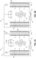
FIG. 4A is a schematic view of a lubrication system for the gearbox ofFIG. 2 during normal operation. -
FIG. 4B is a schematic view of the lubrication system for the gearbox ofFIG. 2 during emergency operation. - Before any embodiments are explained in detail, it is to be understood that the disclosure is not intended to be limited in its application to the details of construction and the arrangement of components set forth in the following description or illustrated in the following drawings. Embodiments are capable of other configurations and of being practiced or of being carried out in various ways.
- Also, it is to be understood that the phraseology and terminology used herein is for the purpose of description and should not be regarded as limited. The use of "including," "comprising" or "having" and variations thereof herein is meant to encompass the items listed thereafter and equivalents thereof as well as additional items. The terms "mounted," "connected" and "coupled" are used broadly and encompass both direct and indirect mounting, connecting and coupling. Further, "connected" and "coupled" are not restricted to physical or mechanical connections or couplings, and may include electrical connections or couplings, whether direct or indirect. Also, electronic communications and notifications may be performed using any known means including direct connections, wireless connections, and the like.
- Referring now to the figures,
FIG. 1 depicts an embodiment of a rotary wing, vertical takeoff and landing (VTOL)aircraft 10. Theaircraft 10 includes anairframe 12, or a body, with an extendingtail 14. A dual, counter rotating, coaxialmain rotor assembly 18 is located at theairframe 12 and rotates about a main rotor axis, A. Themain rotor assembly 18 is driven by a prime mover, for example, one ormore engines 24 via agearbox 26. In some embodiments, theaircraft 10 further includes atranslational thrust system 40 located at the extendingtail 14 to provide translational thrust (forward or rearward) for theaircraft 10. Thetranslational thrust system 40 includes apropeller 42 and is positioned at a tail section of theaircraft 10. Additionally, theaircraft 10 may includelanding gear assemblies 35 extending from below theairframe 12. The illustratedaircraft 10 includes two front landing gear assemblies 35 (right landing gear not shown inFIG. 1 ) and a rearlanding gear assembly 35. In some embodiments, thelanding gear assemblies 35 may be retractable. - The
main rotor assembly 18 includes anupper rotor assembly 28 driven in a first direction (e.g., counter-clockwise) about the main rotor axis, A, and alower rotor assembly 32 driven in a second direction (e.g., clockwise) about the main rotor axis, A, opposite to the first direction (i.e., counter rotating rotors). Each of theupper rotor assembly 28 and thelower rotor assembly 32 includes a plurality ofrotor blades 36 secured to arotor hub 38. Any number ofrotor blades 36 may be used with themain rotor assembly 18. Themain rotor assembly 18 includes a rotor hub fairing 37 generally located between and around the upper and lower rotor assemblies such that therotor hubs 38 are at least partially contained therein. The rotor hub fairing 37 provides drag reduction.Rotor blades 36 are connected to the upper andlower rotor hubs 38 in a hingeless manner, also referred to as a rigid rotor system. Although a particular aircraft configuration is illustrated in this non-limiting embodiment, other rotary-wing aircraft will also benefit from embodiments. Although, the dual rotor system is depicted as coaxial, embodiments include dual rotor aircraft having non-coaxial rotors. Further, a single rotor system could be used as well. - Referring to
FIG. 2 , themain rotor assembly 18 includes amain rotor shaft 46. Thegearbox 26 includes agearbox housing 50 and atransmission element 52 disposed within thegearbox housing 50. Thetransmission element 52 transmits torque from the one ormore engines 24 to themain rotor shaft 46, such that themain rotor shaft 46 rotates about the main rotor axis A. Thegearbox housing 50 includeswalls 54, including both inner and outer walls, that define structure and cavities within thegearbox housing 50. Thewalls 54 of thegearbox housing 50 include aninner surface 54a that faces toward thetransmission element 52 and anouter surface 54b opposite theinner surface 54a. - The
gearbox 26 further includes alubrication system 62 configured to supply lubricant to thetransmission element 52 of thegearbox 26. Thelubrication system 62 includes asump 66 at a bottom of thegearbox housing 50. Thesump 66 is configured to collect lubricant that falls from thetransmission element 52 and functions as a main lubricant reservoir. Thelubrication system 62 further includesconduits 70 for distributing lubricant from thesump 66 to thetransmission element 52, as will be described in more detail below. In the illustrated embodiment, at least oneconduit 70 is formed integrally with at least onewall 54 of thegearbox housing 50. - With reference to
FIGS. 2 and3A , thelubrication system 62 further includes asemi-hollow volume 74 disposed within at least onewall 54 of thegearbox housing 50. In the illustrated embodiment, thesemi-hollow volume 74 is disposed between theinner surface 54a and theouter surface 54b of one of theouter walls 54. In some embodiments, thesemi-hollow volume 74 may be located alternatively or additionally within aninner wall 54 of thegearbox housing 50. Thesemi-hollow volume 74 is configured to store lubricant and functions as an auxiliary lubricant reservoir. In some embodiments, at least twowalls 54 of thegearbox housing 50 may includesemi-hollow volumes 74. In such embodiments, thesemi-hollow volumes 74 may be interconnected via a channel or multiple channels to create a network ofsemi-hollow volumes 74. As such, lubricant can move freely between the at least twosemi-hollow volumes 74 and redundancy in storage space is provided. - An
internal structure 78 is formed within thesemi-hollow volume 74 to provide structural support between theinner surface 54a and theouter surface 54b such that the hollow areas are reinforced with structure to provide sufficient strength and stiffness to thegearbox housing 50. Lubricant stored within thesemi-hollow volume 74 can move freely around theinternal structure 78. In the illustrated embodiment, theinner surface 54a, theouter surface 54b, and theinternal structure 78 are integrally formed via 3D printing. - In the illustrated embodiment, the
internal structure 78 is a lattice structure. In other words, theinternal structure 78 is defined by a distinct, repeating pattern. The lattice structure may be, for example, a surface lattice, a strut lattice, or a planar lattice. Further, the lattice structure may be, for example, a simple cubic lattice, a body-centered cubic lattice, a face-centered cubic lattice, a gyroid lattice, or a hexagonal closest packed lattice. The lattice structure may also be a different type of lattice structure not mentioned herein.FIG. 3B illustrates one example of theinternal structure 78 comprising a cubic lattice, which is an enlarged portion of theinternal structure 78 formed in thesemi-hollow volume 74 of thegearbox housing 50 shown inFIG. 3A . Theinternal structure 78 may also comprise more than one type of lattice structure within thesemi-hollow volume 74. Furthermore, in other embodiments, theinternal structure 78 may not be a lattice structure. - Accordingly, the
internal structure 78 may be optimized to adequately suit the structural and volumetric requirements of the intended application. For example, theinternal structure 78 is engineered to provide sufficient strength and stiffness to accommodate loads and stresses placed on thegearbox housing 50. In some embodiments, thesemi-hollow volume 74 andinternal structure 78 may be included in different or additional areas of thehousing 50 depending on the housing design and where loads are carried. Further, within different parts of thehousing 50, theinternal structure 78 may comprise different shapes and sizes depending upon how much strength or stiffness is needed for certain parts of thehousing 50. - Referring to
FIGS. 4A and 4B , thelubrication system 62 further includes a plurality ofjets sump 66 via theconduits 70. Apump 86 is coupled between thesump 66 and the plurality ofjets sump 66 to thejets jets jets 82a are configured to spray lubricant directly onto thetransmission element 52. A second portion of the plurality ofjets 82b are configured to fill thesemi-hollow volume 74 of the at least onewalls 54 of thegearbox housing 50 with lubricant. In the illustrated embodiment, theinner surface 54a of thewall 54 includes a plurality ofapertures 90 open to an interior of thegearbox housing 50 and in fluid communication with thesemi-hollow volume 74 of thewall 54. In other embodiments, theapertures 90 may be provided on at least oneinner wall 54. Lubricant flows freely from thesemi-hollow volume 74 through theapertures 90, and onto thetransmission element 52. - The
semi-hollow volume 74 of thegearbox housing 50 advantageously allows thelubrication system 62 to function both during a normal operation and an emergency operation of thelubrication system 62. During normal operation, lubricant is supplied to thetransmission element 52 via spraying from the first portion of the plurality ofjets 82a and seeping from thesemi-hollow volumes 74 through theapertures 90 of the wallinner surface 54a of thegearbox housing 50. During operation of theaircraft 10, a component of thelubrication system 62 may become damaged, resulting in decreased functionality of the lubrication system 62 (i.e., emergency operation). For example, thesump 66 may be damaged leading to a loss of lubricant, or thepump 86 may be damaged. Accordingly, during emergency operation, lubricant is no longer delivered to thetransmission element 52 by thejets - Because the
semi-hollow volume 74 of thegearbox housing 50 is constantly filled by the second portion of thejets 82b prior to the emergency operation, lubricant continues to be delivered to thetransmission element 52 through theapertures 90 in the at least onewall 54. Therefore, thetransmission element 52 will continue to be lubricated during emergency operation for a predetermined amount of time such that theaircraft 10 can safely land after sustaining damage. At least oneaperture 90 of thegearbox housing 50 may be positioned adjacent a hot spot of thetransmission element 52. In other words, at least oneaperture 90 of thegearbox housing 50 may be positioned adjacent a component of thetransmission element 52 that is prone to becoming excessively hot during operation of theaircraft 10. As such, components of thetransmission element 52 that present the highest risk of overheating during emergency operation are prioritized for lubricant delivery. Advantageously, thegearbox housing 50 may act as a built-in heat exchanger with improved heat transfer capabilities due to the lubricant contained within thesemi-hollow volume 74. In some embodiments, thesemi-hollow volume 74 may be located adjacent hotspots of thetransmission element 52 to strategically enhance thermal performance of thetransmission element 52. - Various features and advantages are set forth in the following claims.
Claims (15)
- A gearbox comprising:a housing defining an interior, the housing including outer walls and inner walls defining other structure within the housing, wherein at least one wall of the housing includes a semi-hollow volume;a main lubricant reservoir disposed within the interior of the housing; andat least one pump arranged in the interior of the housing for pumping lubricant from the main lubricant reservoir and distributing the lubricant throughout the housing,wherein the semi-hollow volume of the at least one wall stores lubricant during normal operation of the at least one pump, and further wherein when a loss of lubricant occurs within the housing, lubricant seeps from the semi-hollow volume to distribute lubricant throughout the housing.
- The gearbox of claim 1, wherein the semi-hollow volume of the at least one wall at least partially comprises a lattice structure, particularly wherein the at least one wall and the lattice structure are integrally formed as a single structure, optionally wherein the single structure is a 3D printed structure.
- The gearbox of claim 2, wherein the lattice structure is a cubic lattice structure.
- The gearbox of one of claims 1-3, wherein at least two walls of the housing include a semi-hollow volume, and the at least two walls are interconnected via a channel.
- The gearbox of one of claims 1-4, wherein during normal operation of the at least one pump, lubricant seeps from the semi-hollow volume to distribute lubricant within the interior of the housing.
- The gearbox of one of claims 1-5, further including at least one jet fluidly connected to the at least one pump and configured to spray lubricant from the main lubricant reservoir into the housing.
- The gearbox of claim 6, wherein during normal operation of the at least pump, the at least one jet sprays lubricant from the main lubricant reservoir into the housing, and when loss of lubricant occurs, the at least one jet does not spray lubricant into the housing, and/or further including a conduit that couples the main lubricant reservoir to the at least one jet, the conduit being formed integrally with at least one wall of the housing.
- A lubrication system for a gearbox assembly, the lubrication system comprising:a gearbox housing defining an interior, the gearbox housing including outer walls and inner walls defining other structure within the gearbox housing, wherein at least one wall of the gearbox housing includes a semi-hollow volume, the gearbox housing further including a sump that stores lubricant;a transmission element disposed within the interior of the gearbox housing that receives and is lubricated by the lubricant;wherein during normal operation of the lubrication system, lubricant is pumped from the sump and distributed to the transmission element, and lubricant is stored in the semi-hollow volume of the at least one wall, andwherein during emergency operation of the lubrication system, lubricant seeps from the semi-hollow volume to distribute lubricant to the transmission element.
- The lubrication system of claim 8, wherein the semi-hollow volume includes an internal structure, particularly wherein the internal structure at least partially comprises a lattice structure.
- The lubrication system of one of claims 8-9, wherein the at least one wall includes an aperture adjacent a hot spot of the transmission element, the aperture fluidly connected to the semi-hollow volume such that lubricant seeps through the aperture during emergency operation of the lubrication system.
- The lubrication system of one of claims 8-10, wherein during normal operation of the lubrication system, lubricant seeps from the semi-hollow volume to distribute lubricant to the gearbox housing.
- An aircraft comprising:a body;a prime mover supported by the body;a rotary assembly supported by the body;a gearbox mechanically connected between the prime mover and the rotary assembly, the gearbox including,a housing including a plurality of walls, wherein at least one of the plurality of walls includes a semi-hollow volume;a main lubricant reservoir; andat least one pump arranged in the interior of the housing for pumping lubricant from the main lubricant reservoir and distributing lubricant throughout the housing,wherein the semi-hollow volume of the at least one wall stores lubricant during a normal operating condition of the at least one pump, and further wherein during an emergency operating condition, lubricant seeps from the semi-hollow volume to distribute lubricant throughout the housing.
- The aircraft of claim 12, wherein the semi-hollow volume of the at least one of the plurality of walls at least partially comprises a lattice structure.
- The aircraft of claim 12 or 13, wherein the gearbox further includes at least one jet fluidly connected to the at least one pump and configured to spray lubricant from the main lubricant reservoir into the housing, and/or at least one jet fluidly connected to the at least one pump and configured to fill the semi-hollow volume with lubricant.
- The aircraft of one of claims 12-14, wherein the emergency operating condition occurs when a loss of lubricant occurs within the housing.
Applications Claiming Priority (1)
| Application Number | Priority Date | Filing Date | Title |
|---|---|---|---|
| US17/983,218 US12416354B2 (en) | 2022-11-08 | 2022-11-08 | Lubrication system |
Publications (2)
| Publication Number | Publication Date |
|---|---|
| EP4368856A1 true EP4368856A1 (en) | 2024-05-15 |
| EP4368856B1 EP4368856B1 (en) | 2026-02-18 |
Family
ID=88690152
Family Applications (1)
| Application Number | Title | Priority Date | Filing Date |
|---|---|---|---|
| EP23207548.1A Active EP4368856B1 (en) | 2022-11-08 | 2023-11-02 | Gearbox with lubrication system |
Country Status (2)
| Country | Link |
|---|---|
| US (1) | US12416354B2 (en) |
| EP (1) | EP4368856B1 (en) |
Citations (2)
| Publication number | Priority date | Publication date | Assignee | Title |
|---|---|---|---|---|
| DE19615889A1 (en) * | 1996-04-22 | 1997-10-23 | Schaeffler Waelzlager Kg | Re-oiling device prolonging lubricating life of bearing greases in severe environments and reducing maintenance |
| US20200103019A1 (en) * | 2018-09-28 | 2020-04-02 | Ge Avio S.R.L. | System and Method for Emergency Lubricant Flow at an Aircraft Gear Assembly |
Family Cites Families (7)
| Publication number | Priority date | Publication date | Assignee | Title |
|---|---|---|---|---|
| US8793871B2 (en) * | 2011-03-17 | 2014-08-05 | Siemens Energy, Inc. | Process for making a wall with a porous element for component cooling |
| US8931358B2 (en) * | 2012-07-13 | 2015-01-13 | Hiwin Technologies Corp. | Ball screw with a dust-proof and lubricating device |
| US10077664B2 (en) | 2015-12-07 | 2018-09-18 | United Technologies Corporation | Gas turbine engine component having engineered vascular structure |
| US10247296B2 (en) | 2016-12-12 | 2019-04-02 | General Electric Company | Additively manufactured gearbox with integral heat exchanger |
| US11486487B2 (en) | 2018-11-02 | 2022-11-01 | Sikorsky Aircraft Corporation | Gearbox with integrated submersible lubricant pump |
| US11511876B2 (en) * | 2018-12-03 | 2022-11-29 | Textron Innovations Inc. | Variable porosity load-bearing and heat-dissipating aircraft structures |
| US11280396B2 (en) | 2019-11-13 | 2022-03-22 | Rolls-Royce Corporation | Fire resistant gearbox housing |
-
2022
- 2022-11-08 US US17/983,218 patent/US12416354B2/en active Active
-
2023
- 2023-11-02 EP EP23207548.1A patent/EP4368856B1/en active Active
Patent Citations (2)
| Publication number | Priority date | Publication date | Assignee | Title |
|---|---|---|---|---|
| DE19615889A1 (en) * | 1996-04-22 | 1997-10-23 | Schaeffler Waelzlager Kg | Re-oiling device prolonging lubricating life of bearing greases in severe environments and reducing maintenance |
| US20200103019A1 (en) * | 2018-09-28 | 2020-04-02 | Ge Avio S.R.L. | System and Method for Emergency Lubricant Flow at an Aircraft Gear Assembly |
Also Published As
| Publication number | Publication date |
|---|---|
| US12416354B2 (en) | 2025-09-16 |
| US20240151302A1 (en) | 2024-05-09 |
| EP4368856B1 (en) | 2026-02-18 |
Similar Documents
| Publication | Publication Date | Title |
|---|---|---|
| EP3931093B1 (en) | Aircraft having hybrid-electric propulsion system with electric storage located in fuselage | |
| EP3514406B1 (en) | Aircraft lubrication system | |
| EP3447267B1 (en) | Supplemental lubrication pressurized by component or reservoir rotation | |
| US12163584B2 (en) | Hybrid pressurized and non-pressurized lubrication system for aircraft gearbox | |
| EP3730816B1 (en) | Low profile auxiliary lubrication system | |
| HU231231B1 (en) | Cooling lubrication system with dry oil sump | |
| US8172182B2 (en) | Aircraft spillover fuel tank | |
| US9815553B2 (en) | Independent hydraulic control system for rotorcraft secondary rotor | |
| CA3055846A1 (en) | Engine assembly with porous surface of boundary layer suction | |
| US11313455B2 (en) | Aircraft gearbox lubrication system with multiple lubrication subsystems | |
| US12416354B2 (en) | Lubrication system | |
| US8970059B2 (en) | Ram air turbine generator housing | |
| US20260077876A1 (en) | Propulsion System for Electric Aircraft | |
| CN108945424B (en) | Rotor blade root structure | |
| US11852232B1 (en) | Persistent lubrication systems for aircraft gearboxes | |
| CN110963018A (en) | A Modular Unmanned Helicopter Oriented to Configuration and Mission Systems | |
| EP3647630B1 (en) | Rotorcraft | |
| EP2615345B1 (en) | Overshaft fluid transfer coupling arrangement and assembly method thereof | |
| US8622176B2 (en) | Gearbox oil reservoir shape optimization | |
| EP3854682B1 (en) | Helicopter | |
| EP4328133A1 (en) | Rotary shaft for an aircraft | |
| US12202599B2 (en) | Autonomous emergency lubrication of aircraft gearboxes | |
| EP1486675A1 (en) | Aeronautical generator | |
| RU2140379C1 (en) | Aircraft fuel system | |
| JP7421331B2 (en) | helicopter transmission structure |
Legal Events
| Date | Code | Title | Description |
|---|---|---|---|
| PUAI | Public reference made under article 153(3) epc to a published international application that has entered the european phase |
Free format text: ORIGINAL CODE: 0009012 |
|
| STAA | Information on the status of an ep patent application or granted ep patent |
Free format text: STATUS: THE APPLICATION HAS BEEN PUBLISHED |
|
| AK | Designated contracting states |
Kind code of ref document: A1 Designated state(s): AL AT BE BG CH CY CZ DE DK EE ES FI FR GB GR HR HU IE IS IT LI LT LU LV MC ME MK MT NL NO PL PT RO RS SE SI SK SM TR |
|
| STAA | Information on the status of an ep patent application or granted ep patent |
Free format text: STATUS: REQUEST FOR EXAMINATION WAS MADE |
|
| 17P | Request for examination filed |
Effective date: 20240827 |
|
| RBV | Designated contracting states (corrected) |
Designated state(s): AL AT BE BG CH CY CZ DE DK EE ES FI FR GB GR HR HU IE IS IT LI LT LU LV MC ME MK MT NL NO PL PT RO RS SE SI SK SM TR |
|
| GRAP | Despatch of communication of intention to grant a patent |
Free format text: ORIGINAL CODE: EPIDOSNIGR1 |
|
| STAA | Information on the status of an ep patent application or granted ep patent |
Free format text: STATUS: GRANT OF PATENT IS INTENDED |
|
| RIC1 | Information provided on ipc code assigned before grant |
Ipc: F16H 57/04 20100101AFI20251006BHEP Ipc: F16H 57/032 20120101ALI20251006BHEP |
|
| INTG | Intention to grant announced |
Effective date: 20251031 |
|
| GRAS | Grant fee paid |
Free format text: ORIGINAL CODE: EPIDOSNIGR3 |
|
| GRAA | (expected) grant |
Free format text: ORIGINAL CODE: 0009210 |
|
| STAA | Information on the status of an ep patent application or granted ep patent |
Free format text: STATUS: THE PATENT HAS BEEN GRANTED |
|
| AK | Designated contracting states |
Kind code of ref document: B1 Designated state(s): AL AT BE BG CH CY CZ DE DK EE ES FI FR GB GR HR HU IE IS IT LI LT LU LV MC ME MK MT NL NO PL PT RO RS SE SI SK SM TR |
|
| REG | Reference to a national code |
Ref country code: CH Ref legal event code: F10 Free format text: ST27 STATUS EVENT CODE: U-0-0-F10-F00 (AS PROVIDED BY THE NATIONAL OFFICE) Effective date: 20260218 Ref country code: GB Ref legal event code: FG4D |
|
| REG | Reference to a national code |
Ref country code: IE Ref legal event code: FG4D |
|
| REG | Reference to a national code |
Ref country code: DE Ref legal event code: R096 Ref document number: 602023012162 Country of ref document: DE |