EP4368846A1 - Modular support assembly - Google Patents
Modular support assembly Download PDFInfo
- Publication number
- EP4368846A1 EP4368846A1 EP23205424.7A EP23205424A EP4368846A1 EP 4368846 A1 EP4368846 A1 EP 4368846A1 EP 23205424 A EP23205424 A EP 23205424A EP 4368846 A1 EP4368846 A1 EP 4368846A1
- Authority
- EP
- European Patent Office
- Prior art keywords
- mounting surface
- support assembly
- casing
- bearing unit
- metal insert
- Prior art date
- Legal status (The legal status is an assumption and is not a legal conclusion. Google has not performed a legal analysis and makes no representation as to the accuracy of the status listed.)
- Granted
Links
Images


Classifications
-
- F—MECHANICAL ENGINEERING; LIGHTING; HEATING; WEAPONS; BLASTING
- F16—ENGINEERING ELEMENTS AND UNITS; GENERAL MEASURES FOR PRODUCING AND MAINTAINING EFFECTIVE FUNCTIONING OF MACHINES OR INSTALLATIONS; THERMAL INSULATION IN GENERAL
- F16C—SHAFTS; FLEXIBLE SHAFTS; ELEMENTS OR CRANKSHAFT MECHANISMS; ROTARY BODIES OTHER THAN GEARING ELEMENTS; BEARINGS
- F16C35/00—Rigid support of bearing units; Housings, e.g. caps, covers
- F16C35/04—Rigid support of bearing units; Housings, e.g. caps, covers in the case of ball or roller bearings
- F16C35/042—Housings for rolling element bearings for rotary movement
-
- F—MECHANICAL ENGINEERING; LIGHTING; HEATING; WEAPONS; BLASTING
- F16—ENGINEERING ELEMENTS AND UNITS; GENERAL MEASURES FOR PRODUCING AND MAINTAINING EFFECTIVE FUNCTIONING OF MACHINES OR INSTALLATIONS; THERMAL INSULATION IN GENERAL
- F16C—SHAFTS; FLEXIBLE SHAFTS; ELEMENTS OR CRANKSHAFT MECHANISMS; ROTARY BODIES OTHER THAN GEARING ELEMENTS; BEARINGS
- F16C23/00—Bearings for exclusively rotary movement adjustable for aligning or positioning
- F16C23/06—Ball or roller bearings
- F16C23/08—Ball or roller bearings self-adjusting
- F16C23/082—Ball or roller bearings self-adjusting by means of at least one substantially spherical surface
- F16C23/084—Ball or roller bearings self-adjusting by means of at least one substantially spherical surface sliding on a complementary spherical surface
-
- F—MECHANICAL ENGINEERING; LIGHTING; HEATING; WEAPONS; BLASTING
- F16—ENGINEERING ELEMENTS AND UNITS; GENERAL MEASURES FOR PRODUCING AND MAINTAINING EFFECTIVE FUNCTIONING OF MACHINES OR INSTALLATIONS; THERMAL INSULATION IN GENERAL
- F16C—SHAFTS; FLEXIBLE SHAFTS; ELEMENTS OR CRANKSHAFT MECHANISMS; ROTARY BODIES OTHER THAN GEARING ELEMENTS; BEARINGS
- F16C19/00—Bearings with rolling contact, for exclusively rotary movement
- F16C19/02—Bearings with rolling contact, for exclusively rotary movement with bearing balls essentially of the same size in one or more circular rows
- F16C19/14—Bearings with rolling contact, for exclusively rotary movement with bearing balls essentially of the same size in one or more circular rows for both radial and axial load
- F16C19/16—Bearings with rolling contact, for exclusively rotary movement with bearing balls essentially of the same size in one or more circular rows for both radial and axial load with a single row of balls
-
- F—MECHANICAL ENGINEERING; LIGHTING; HEATING; WEAPONS; BLASTING
- F16—ENGINEERING ELEMENTS AND UNITS; GENERAL MEASURES FOR PRODUCING AND MAINTAINING EFFECTIVE FUNCTIONING OF MACHINES OR INSTALLATIONS; THERMAL INSULATION IN GENERAL
- F16C—SHAFTS; FLEXIBLE SHAFTS; ELEMENTS OR CRANKSHAFT MECHANISMS; ROTARY BODIES OTHER THAN GEARING ELEMENTS; BEARINGS
- F16C33/00—Parts of bearings; Special methods for making bearings or parts thereof
- F16C33/30—Parts of ball or roller bearings
- F16C33/58—Raceways; Race rings
- F16C33/583—Details of specific parts of races
-
- F—MECHANICAL ENGINEERING; LIGHTING; HEATING; WEAPONS; BLASTING
- F16—ENGINEERING ELEMENTS AND UNITS; GENERAL MEASURES FOR PRODUCING AND MAINTAINING EFFECTIVE FUNCTIONING OF MACHINES OR INSTALLATIONS; THERMAL INSULATION IN GENERAL
- F16C—SHAFTS; FLEXIBLE SHAFTS; ELEMENTS OR CRANKSHAFT MECHANISMS; ROTARY BODIES OTHER THAN GEARING ELEMENTS; BEARINGS
- F16C33/00—Parts of bearings; Special methods for making bearings or parts thereof
- F16C33/72—Sealings
- F16C33/76—Sealings of ball or roller bearings
- F16C33/78—Sealings of ball or roller bearings with a diaphragm, disc, or ring, with or without resilient members
- F16C33/7803—Sealings of ball or roller bearings with a diaphragm, disc, or ring, with or without resilient members suited for particular types of rolling bearings
- F16C33/7806—Sealings of ball or roller bearings with a diaphragm, disc, or ring, with or without resilient members suited for particular types of rolling bearings for spherical roller bearings
-
- F—MECHANICAL ENGINEERING; LIGHTING; HEATING; WEAPONS; BLASTING
- F16—ENGINEERING ELEMENTS AND UNITS; GENERAL MEASURES FOR PRODUCING AND MAINTAINING EFFECTIVE FUNCTIONING OF MACHINES OR INSTALLATIONS; THERMAL INSULATION IN GENERAL
- F16C—SHAFTS; FLEXIBLE SHAFTS; ELEMENTS OR CRANKSHAFT MECHANISMS; ROTARY BODIES OTHER THAN GEARING ELEMENTS; BEARINGS
- F16C35/00—Rigid support of bearing units; Housings, e.g. caps, covers
- F16C35/04—Rigid support of bearing units; Housings, e.g. caps, covers in the case of ball or roller bearings
- F16C35/06—Mounting or dismounting of ball or roller bearings; Fixing them onto shaft or in housing
- F16C35/07—Fixing them on the shaft or housing with interposition of an element
- F16C35/077—Fixing them on the shaft or housing with interposition of an element between housing and outer race ring
-
- F—MECHANICAL ENGINEERING; LIGHTING; HEATING; WEAPONS; BLASTING
- F16—ENGINEERING ELEMENTS AND UNITS; GENERAL MEASURES FOR PRODUCING AND MAINTAINING EFFECTIVE FUNCTIONING OF MACHINES OR INSTALLATIONS; THERMAL INSULATION IN GENERAL
- F16C—SHAFTS; FLEXIBLE SHAFTS; ELEMENTS OR CRANKSHAFT MECHANISMS; ROTARY BODIES OTHER THAN GEARING ELEMENTS; BEARINGS
- F16C19/00—Bearings with rolling contact, for exclusively rotary movement
- F16C19/02—Bearings with rolling contact, for exclusively rotary movement with bearing balls essentially of the same size in one or more circular rows
- F16C19/04—Bearings with rolling contact, for exclusively rotary movement with bearing balls essentially of the same size in one or more circular rows for radial load mainly
- F16C19/06—Bearings with rolling contact, for exclusively rotary movement with bearing balls essentially of the same size in one or more circular rows for radial load mainly with a single row or balls
-
- F—MECHANICAL ENGINEERING; LIGHTING; HEATING; WEAPONS; BLASTING
- F16—ENGINEERING ELEMENTS AND UNITS; GENERAL MEASURES FOR PRODUCING AND MAINTAINING EFFECTIVE FUNCTIONING OF MACHINES OR INSTALLATIONS; THERMAL INSULATION IN GENERAL
- F16C—SHAFTS; FLEXIBLE SHAFTS; ELEMENTS OR CRANKSHAFT MECHANISMS; ROTARY BODIES OTHER THAN GEARING ELEMENTS; BEARINGS
- F16C2220/00—Shaping
- F16C2220/02—Shaping by casting
- F16C2220/04—Shaping by casting by injection-moulding
-
- F—MECHANICAL ENGINEERING; LIGHTING; HEATING; WEAPONS; BLASTING
- F16—ENGINEERING ELEMENTS AND UNITS; GENERAL MEASURES FOR PRODUCING AND MAINTAINING EFFECTIVE FUNCTIONING OF MACHINES OR INSTALLATIONS; THERMAL INSULATION IN GENERAL
- F16C—SHAFTS; FLEXIBLE SHAFTS; ELEMENTS OR CRANKSHAFT MECHANISMS; ROTARY BODIES OTHER THAN GEARING ELEMENTS; BEARINGS
- F16C2226/00—Joining parts; Fastening; Assembling or mounting parts
- F16C2226/50—Positive connections
- F16C2226/70—Positive connections with complementary interlocking parts
- F16C2226/72—Positive connections with complementary interlocking parts with bayonet joints, i.e. parts are rotated to create positive interlock
Definitions
- the present invention relates to a support assembly.
- the present invention relates to a modular support assembly for applications in the food industry, to which the description below will make specific reference without thereby losing its general nature.
- the support assemblies of the known type are formed by a casing made of composite material (for example, glass fibre reinforced plastic material) and provided with a flange for fixing to the frame of a machine, a bearing unit, which is located inside the casing in order to support a moving shaft and is provided with a spherical coupling for coupling with the said casing in order to compensate for possible static mounting misalignment of the moving shaft with respect to the fixed frame.
- a casing made of composite material (for example, glass fibre reinforced plastic material) and provided with a flange for fixing to the frame of a machine
- a bearing unit which is located inside the casing in order to support a moving shaft and is provided with a spherical coupling for coupling with the said casing in order to compensate for possible static mounting misalignment of the moving shaft with respect to the fixed frame.
- the bearing unit may not be mounted in its operating position inside a spherical mounting surface of the casing since it would interfere with the mounting surface itself. Therefore, mounting of the bearing unit is performed by inserting the bearing unit in a position rotated by 90° with respect to the operating position.
- the mounting surface of the casing also has a pair of insertion recesses: the presence of these insertion recesses, namely the absence of material, therefore allows rotation through 90° of the bearing unit thus inserted and positioning thereof in its operating position.
- This special feature for ensuring the correct mounting of the bearing unit also helps facilitate the procedure for measuring the alignment torque of the support assembly.
- This test has the function of checking the degree of precision of the spherical coupling between bearing unit and casing, where, as may be deduced, the coupling must not be either too tight in order to avoid transmitting excessive tension to the moving shaft, nor too loose to ensure that the bearing unit is not movable inside the seat of the casing and, consequently, is unable to withstand and transmit the load under operating conditions.
- the defects present on the surfaces of the casing and in particular present on the spherical mounting surface are absolutely unacceptable and result in a large number of components being discarded.
- the object of the present invention is to provide a support assembly for applications in the food industry which does not have the aforementioned drawbacks.
- 1 denotes overall a support assembly which is particularly suitable for being arranged between a first mechanical element 2 and a second mechanical element 3, preferably, but not exclusively comprising a stationary frame 2 and a rotating shaft of a food industry machine (both of the known type and therefore only schematically shown in the Figures).
- the support assembly 1 comprises a central axis X and comprises:
- the bearing unit 30 in turn comprises:
- the support assembly 1 has the metal insert 40 which is interposed radially between the casing 10 and the bearing unit 30.
- the casing 10 is co-moulded with the metal insert 40.
- the metal insert 40 is made as a single piece and comprises a pair of insertion recesses 45 configured to allow the insertion of the bearing unit 30 inside the spherical mounting surface 41 and the rotation of the bearing unit itself so that it is positioned in the mounting configuration.
- the insertion recesses 45 are formed along the spherical mounting surface 41 of the metal insert 40 and have a circumferential development with an angular opening of the about 30°.
- Mounting of the bearing unit is performed by inserting the bearing unit in a position rotated by 90° with respect to the operating position.
- the presence of the insertion recesses 45, namely the absence of material, therefore allows rotation through 90° of the bearing unit thus inserted and positioning thereof in its operating position.
- the metal insert 40 has, finally, a plurality of radially external protuberances 42 which, in the example shown in Figure 2 , are four in number and are uniformly distributed at an angular distance of 90°.
- the protuberances 42 have a substantially parallelepiped shape.
- the protuberances 42 during co-moulding with the casing 10, will form along the mounting surface 11 of the casing respective radially internal anchoring grooves 12.
- the metal insert 40 is formed as two half-shells 40', 40" with a substantially semi-cylindrical shape, arranged adjacent to each other and symmetrical with respect to an axis Y transverse to the support assembly.
- the advantage of this second embodiment is that it allows mounting of the bearing unit 30 immediately in its operating position, with arrangement around it of the two half-shells 40', 40".
- Each of the two half-shells 40', 40" is provided with a plurality of radially external protuberances 42, each of which has a corresponding through-hole 43 inside which a connecting pin 43 is received for ensuring the stable locking together of the two half-shells 40', 40".
- the protuberances 42 have a substantially parallelepiped shape, namely a shape identical to the shape of the protuberances of the first embodiment of the invention.
- the protuberances 42 during co-moulding with the casing 10, will form along the mounting surface 11 of the casing respective radially internal anchoring grooves 12.
- the housing which is created co-moulding of the protuberances 42 inside the corresponding anchoring grooves 12 also forms, for this second embodiment, an effective device for preventing rotation of the casing 10 with respect to the metal insert 40, namely the two half-shells 40', 40".
- the protuberances 42 and the corresponding through-holes 43 are four in number for each half-shell 40', 40", being angularly spaced at 90°, and the connecting pins 44 are also four in number and angularly spaced at 90°.
- the protuberances 42 perform two functions: that of allowing housing of the connecting pins 44 of the two half-shells 40', 40" and that of acting as a device for preventing rotation.
- the operation of co-moulding the casing may be performed after the bearing unit 30 and the two half-shells 40', 40" have already been mounted.
- each of the two half-shells 40', 40" of the metal insert 40 may also be provided with two insertion recesses 45 configured, as in the first embodiment, to allow the insertion of the bearing unit 30 inside the further spherical mounting surface 41 and the rotation of the bearing unit 30 itself so that it is positioned in the mounting configuration.
- the insertion recesses 45 are formed along the spherical mounting surface 41 of the two half-shells 40', 40" of the metal insert 40 and have a circumferential development with an angular opening of the about 30°.
- insertion recesses 45 are not necessary in this second embodiment in which the metal insert 40 is formed by the two half-shells 40', 40" and therefore the same embodiment may also be without the insertion recesses 45.
- the casing 10 always has the same diameter of the mounting surface 11 and the metal insert 40 may be adapted to different configurations of the shaft 2 and consequent bearing units 30 with a different diameter of the spherical mounting surface 39 of the radially outer ring 31.
- the diameter of the spherical mounting surface 41 of the metal insert 40 is not predefined, but in each case is adapted (i.e. is substantially equal to) the diameter of the spherical mounting surface 39 of the radially outer ring 31 of the bearing unit 30.
- the present invention offers the following advantages:
Landscapes
- Engineering & Computer Science (AREA)
- General Engineering & Computer Science (AREA)
- Mechanical Engineering (AREA)
- Support Of The Bearing (AREA)
- Pivots And Pivotal Connections (AREA)
- Mounting Of Bearings Or Others (AREA)
Abstract
- a casing (10) made of composite material and having a radially internal mounting surface (11);
- a bearing unit (30) housed inside the casing (10) and provided with a radially external ring (31) having a radially external, spherical, mounting surface (39);
wherein
- a metal insert (4) is interposed between the casing (10) and the bearing unit (30) and is housed inside the mounting surface (11) of the casing (10); and
- the metal insert (4) is provided with a radially internal, spherical, mounting surface (41), inside which the bearing unit (30) is housed.
Description
- The present invention relates to a support assembly.
- In particular, the present invention relates to a modular support assembly for applications in the food industry, to which the description below will make specific reference without thereby losing its general nature.
- In the food industry the support assemblies of the known type are formed by a casing made of composite material (for example, glass fibre reinforced plastic material) and provided with a flange for fixing to the frame of a machine, a bearing unit, which is located inside the casing in order to support a moving shaft and is provided with a spherical coupling for coupling with the said casing in order to compensate for possible static mounting misalignment of the moving shaft with respect to the fixed frame.
- Owing to the spherical coupling, the bearing unit may not be mounted in its operating position inside a spherical mounting surface of the casing since it would interfere with the mounting surface itself. Therefore, mounting of the bearing unit is performed by inserting the bearing unit in a position rotated by 90° with respect to the operating position. The mounting surface of the casing also has a pair of insertion recesses: the presence of these insertion recesses, namely the absence of material, therefore allows rotation through 90° of the bearing unit thus inserted and positioning thereof in its operating position.
- This special feature for ensuring the correct mounting of the bearing unit also helps facilitate the procedure for measuring the alignment torque of the support assembly. This test has the function of checking the degree of precision of the spherical coupling between bearing unit and casing, where, as may be deduced, the coupling must not be either too tight in order to avoid transmitting excessive tension to the moving shaft, nor too loose to ensure that the bearing unit is not movable inside the seat of the casing and, consequently, is unable to withstand and transmit the load under operating conditions.
- In applications for the food industry, since the casing is made of a composite material and is therefore subject to irregular shrinkage during cooling following the hot-moulding step, correct values for correct coupling between bearing unit made of metal and casing made of composite material risk nevertheless causing abrasions on the casing.
- The defects present on the surfaces of the casing and in particular present on the spherical mounting surface (for example visible fractures, exposed glass fibres, etc.) are absolutely unacceptable and result in a large number of components being discarded.
- Finally, in some applications, including those in the food industry, the end user on occasions must reduce or increase the size of the shaft (and consequently of the bearing unit) without having to change the machine frame. As a result it is impossible to find a feasible solution for adapting a different-size bearing unit within the same casing. In particular, should there be an increase in the dimensions of the shaft and the bearing unit, it is not possible to imagine re-machining the casing mounting surface in order to widen it, without affecting the rest of the casing: the high degree of vibrations would reduce the strength of the casing itself.
- The object of the present invention is to provide a support assembly for applications in the food industry which does not have the aforementioned drawbacks.
- According to the present invention a modular support assembly having the characteristic features described in the attached claims is provided.
- The invention will now be described with reference to the attached drawings which illustrate some non-limiting examples of embodiment of the invention, in which:
-
Figure 1 shows a cross-sectional view of a first preferred embodiment of a support assembly provided in accordance with the present invention; -
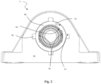
Figure 2 shows a front view of the support assembly ofFigure 1 ; -
Figure 3 shows a cross-sectional view of a second preferred embodiment of a support assembly provided in accordance with the present invention; and -
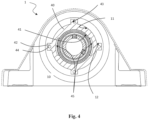
Figure 4 shows a front view of the support assembly ofFigure 3 . - With reference to
Figures 1 and2 , 1 denotes overall a support assembly which is particularly suitable for being arranged between a firstmechanical element 2 and a secondmechanical element 3, preferably, but not exclusively comprising astationary frame 2 and a rotating shaft of a food industry machine (both of the known type and therefore only schematically shown in the Figures). - According to this first preferred embodiment, the
support assembly 1 comprises a central axis X and comprises: - a flanged
casing 10, preferably made of composite material, suitable for mounting on the frame and provided internally with a radiallyinternal mounting surface 11; - a
metal insert 40 mounted inside themounting surface 11 of thecasing 10 and having a radially internal, spherical, mountingsurface 41; and - a
bearing unit 30 mounted inside thespherical mounting surface 41 and supporting the rotatingshaft 3. Thebearing unit 30 is also provided with a sealing device (of the known type and therefore not shown) arranged on opposite sides of thebearing unit 30 in order to prevent any entry of washing fluids or other contaminants inside thebearing unit 30. - The
bearing unit 30 in turn comprises: - a convex and stationary radially
outer ring 31, provided with a radially external, spherical, mountingsurface 39; - a radially
inner ring 33, rotatable about the central axis X and provided with afixing device 34 for fixing thebearing unit 30 to the rotatingshaft 3; and - a plurality of
rolling members 32, in particular spheres, arranged between the radiallyouter ring 31 and the radiallyinner ring 33 for relative rotation of the radiallyinner ring 33 with respect to the radiallyouter ring 31. - In all of the present description and in the claims, the terms and the expressions indicating positions and orientations such as "radial" and "axial" are understood as being in relation to the central axis of rotation X of the
bearing unit 30. - Therefore, the
support assembly 1 according to the present invention has themetal insert 40 which is interposed radially between thecasing 10 and thebearing unit 30. - In this way the mounting of the
bearing unit 30 inside thespherical mounting surface 41 and setting of the correct alignment torque do not create problems since the spherical coupling (between the radially external, spherical, mountingsurface 39 of the radiallyouter ring 31 and the radially internal, spherical, mountingsurface 41 of the metal insert 40) is realized between two metal surfaces and therefore may be sufficiently precise without creating damage to one of the two surfaces. - Advantageously, the
casing 10 is co-moulded with themetal insert 40. - According to a first preferred embodiment of the invention, the
metal insert 40 is made as a single piece and comprises a pair ofinsertion recesses 45 configured to allow the insertion of thebearing unit 30 inside thespherical mounting surface 41 and the rotation of the bearing unit itself so that it is positioned in the mounting configuration. Theinsertion recesses 45 are formed along thespherical mounting surface 41 of themetal insert 40 and have a circumferential development with an angular opening of the about 30°. - Mounting of the bearing unit is performed by inserting the bearing unit in a position rotated by 90° with respect to the operating position. The presence of the
insertion recesses 45, namely the absence of material, therefore allows rotation through 90° of the bearing unit thus inserted and positioning thereof in its operating position. - The
metal insert 40 has, finally, a plurality of radiallyexternal protuberances 42 which, in the example shown inFigure 2 , are four in number and are uniformly distributed at an angular distance of 90°. Theprotuberances 42 have a substantially parallelepiped shape. - The
protuberances 42, during co-moulding with thecasing 10, will form along themounting surface 11 of the casing respective radiallyinternal anchoring grooves 12. The housing which is created co-moulding of theprotuberances 42 inside thecorresponding anchoring grooves 12 forms an effective device for preventing rotation of thecasing 10 with respect to themetal insert 40. - With reference to
Figures 3 and4 , in a second preferred embodiment of the invention, themetal insert 40 is formed as two half-shells 40', 40" with a substantially semi-cylindrical shape, arranged adjacent to each other and symmetrical with respect to an axis Y transverse to the support assembly. The advantage of this second embodiment is that it allows mounting of thebearing unit 30 immediately in its operating position, with arrangement around it of the two half-shells 40', 40". - Each of the two half-
shells 40', 40" is provided with a plurality of radiallyexternal protuberances 42, each of which has a corresponding through-hole 43 inside which a connectingpin 43 is received for ensuring the stable locking together of the two half-shells 40', 40". Theprotuberances 42 have a substantially parallelepiped shape, namely a shape identical to the shape of the protuberances of the first embodiment of the invention. - The
protuberances 42, during co-moulding with thecasing 10, will form along themounting surface 11 of the casing respective radiallyinternal anchoring grooves 12. The housing which is created co-moulding of theprotuberances 42 inside thecorresponding anchoring grooves 12 also forms, for this second embodiment, an effective device for preventing rotation of thecasing 10 with respect to themetal insert 40, namely the two half-shells 40', 40". - Preferably, the
protuberances 42 and the corresponding through-holes 43 are four in number for each half-shell 40', 40", being angularly spaced at 90°, and the connectingpins 44 are also four in number and angularly spaced at 90°. - Therefore, in this second embodiment, the
protuberances 42 perform two functions: that of allowing housing of the connectingpins 44 of the two half-shells 40', 40" and that of acting as a device for preventing rotation. - Advantageously, the operation of co-moulding the casing may be performed after the
bearing unit 30 and the two half-shells 40', 40" have already been mounted. - In this second embodiment, each of the two half-
shells 40', 40" of themetal insert 40 may also be provided with twoinsertion recesses 45 configured, as in the first embodiment, to allow the insertion of thebearing unit 30 inside the furtherspherical mounting surface 41 and the rotation of thebearing unit 30 itself so that it is positioned in the mounting configuration. Theinsertion recesses 45 are formed along thespherical mounting surface 41 of the two half-shells 40', 40" of themetal insert 40 and have a circumferential development with an angular opening of the about 30°. - It is clear that the
insertion recesses 45 are not necessary in this second embodiment in which themetal insert 40 is formed by the two half-shells 40', 40" and therefore the same embodiment may also be without theinsertion recesses 45. - Owing to the presence of the
insertion recesses 45, however, it is possible to achieve standardization of the production, with the possibility of performing, as required, mounting of thebearing unit 30 together with the two half-shells 40', 40" and co-moulding ofcasing 10 onto this subassembly or, vice versa, co-moulding of thecasing 10 with the two half-shells only and, then, mounting inside thebearing unit 30. - Whatever the configuration prechosen from among those described above, with the present invention it is possible to obtain a set of modular configurations in which the
casing 10 always has the same diameter of themounting surface 11 and themetal insert 40 may be adapted to different configurations of theshaft 2 andconsequent bearing units 30 with a different diameter of thespherical mounting surface 39 of the radiallyouter ring 31. In other words, the diameter of thespherical mounting surface 41 of themetal insert 40 is not predefined, but in each case is adapted (i.e. is substantially equal to) the diameter of thespherical mounting surface 39 of the radiallyouter ring 31 of thebearing unit 30. - To summarise, the present invention offers the following advantages:
- it is possible to standardize the casing by providing, for the solutions which require it, only one or more seats for housing the protuberances of the metal insert;
- the modularity is obtained simply by providing different metal inserts which differ only in terms of the diameter of the radially internal, spherical, mounting surface which will house corresponding bearing units with a different-size spherical mounting surface;
- in the configuration of the metal insert formed by two half-shells, the axial tightening together of the two metal half-shells is ensured by the presence of the connecting pins. This solution guarantees both a high nominal load and easy mounting;
- the solution of the metal insert formed by two half-shells does not necessarily require even the presence of the insertion recesses for subsequent mounting of the bearing unit.
- Finally, with this solution it is possible to obtain correct values of the alignment torque without the risk of damaging the casing made of composite material.
- In addition to the embodiments of the invention, as described above, it is to be understood that numerous further variants exist. It must also be understood that said embodiments are only examples and do not limit either the scope of the invention, nor its applications, nor its possible configurations. On the contrary, although the description provided above enables the person skilled in the art to implement the present invention at least in one of its examples of configuration, it must be understood that numerous variations of the components described are feasible, without thereby departing from the scope of the invention, as defined in the accompanying claims, interpreted literally and/or in accordance with their legal equivalents.
Claims (10)
- Support assembly (1) having a central axis (X) and comprising:- a casing (10) made of composite material and comprising a radially internal mounting surface (11),- a bearing unit (30) housed inside the casing (10) and provided with a radially outer ring (31) having a radially external, spherical, mounting surface (39),the support assembly (1) being characterized in that, in combination:- a metal insert (40) is interposed between the casing (10) and the bearing unit (30) and is housed inside the mounting surface (11) of the casing (10), and- the metal insert (40) is provided with a radially internal, spherical, mounting surface (41), inside which the bearing unit (30) is housed.
- Support assembly (1) according to Claim 1, wherein the metal insert (40) is made as a single piece and comprises two insertion recesses (45) formed along the spherical mounting surface (41) of the metal insert (40) and configured to allow insertion of the bearing unit (30) inside the spherical mounting surface (41) and rotation of the bearing unit into the operating position.
- Support assembly (1) according to Claim 2, wherein the metal insert (40) has a plurality of radially external protuberances (42), with a substantially parallelepiped shape, which, during operation, are housed in respective anchoring grooves (12) present on the mounting surface (11) of the casing (10).
- Support assembly (1) according to Claim 3, wherein the protuberances (42) are four in number and uniformly distributed at an angular distance of 90°.
- Support assembly (1) according to Claim 1, wherein the metal support (40) is made of two half-shells (40', 40") with a substantially semi-cylindrical shape, arranged adjacent to each other and symmetrical with each other relative to an axis (Y) transverse to the support assembly.
- Support assembly (1) according to Claim 5, wherein each of the two half-shells (40', 40") is provided with a plurality of radially external protuberances (42), with a substantially parallelepiped shape, each of the protuberances (42) having a corresponding through-hole (43) inside which a connecting pin (44) is received for ensuring the stable locking together of the two half-shells (40', 40").
- Support assembly (1) according to Claim 6, wherein the protuberances (42), the corresponding through-holes (43) and the connecting pins (44) are four in number for each half-shell (40', 40") and angularly spaced at 90°.
- Support assembly (1) according to one of Claims 5 to 7, wherein each of the two half-shells (40', 40") of the metal insert (40) is provided with two insertion recesses (45) formed along the spherical mounting surface (41) of the metal insert (40).
- Support assembly (1) according to one of the preceding claims, wherein the diameter of the mounting surface (11) of the casing (10) is predefined, while the diameter of the spherical mounting surface (41) of the metal insert (40) is not predefined but is substantially equal to the diameter of the spherical mounting surface (39) of the radially outer ring (31) of the bearing unit (30).
- Support assembly (1) according to one of the preceding claims, wherein the casing (10) is co-moulded with the metal insert (40).
Applications Claiming Priority (1)
| Application Number | Priority Date | Filing Date | Title |
|---|---|---|---|
| IT102022000023283A IT202200023283A1 (en) | 2022-11-11 | 2022-11-11 | MODULAR SUPPORT COMPLEX |
Publications (3)
| Publication Number | Publication Date |
|---|---|
| EP4368846A1 true EP4368846A1 (en) | 2024-05-15 |
| EP4368846B1 EP4368846B1 (en) | 2026-06-03 |
| EP4368846C0 EP4368846C0 (en) | 2026-06-03 |
Family
ID=85122633
Family Applications (1)
| Application Number | Title | Priority Date | Filing Date |
|---|---|---|---|
| EP23205424.7A Active EP4368846B1 (en) | 2022-11-11 | 2023-10-24 | Modular support assembly |
Country Status (4)
| Country | Link |
|---|---|
| US (1) | US20240159274A1 (en) |
| EP (1) | EP4368846B1 (en) |
| CN (1) | CN118030700A (en) |
| IT (1) | IT202200023283A1 (en) |
Citations (4)
| Publication number | Priority date | Publication date | Assignee | Title |
|---|---|---|---|---|
| US2397164A (en) * | 1943-03-08 | 1946-03-26 | Julius E Shafer | Self-aligning bearing assembly |
| US20100046867A1 (en) * | 2008-08-22 | 2010-02-25 | Reliance Electric Technologies, Llc | Waveform Expansion Sleeve for a Bearing |
| WO2021160640A1 (en) * | 2020-02-11 | 2021-08-19 | Martin Metterhausen | Bearing assembly |
| US20220243770A1 (en) * | 2021-02-03 | 2022-08-04 | Aktiebolaget Skf | Reinforced casing for food applications |
-
2022
- 2022-11-11 IT IT102022000023283A patent/IT202200023283A1/en unknown
-
2023
- 2023-10-24 EP EP23205424.7A patent/EP4368846B1/en active Active
- 2023-10-31 US US18/385,459 patent/US20240159274A1/en active Pending
- 2023-11-08 CN CN202311478837.2A patent/CN118030700A/en active Pending
Patent Citations (4)
| Publication number | Priority date | Publication date | Assignee | Title |
|---|---|---|---|---|
| US2397164A (en) * | 1943-03-08 | 1946-03-26 | Julius E Shafer | Self-aligning bearing assembly |
| US20100046867A1 (en) * | 2008-08-22 | 2010-02-25 | Reliance Electric Technologies, Llc | Waveform Expansion Sleeve for a Bearing |
| WO2021160640A1 (en) * | 2020-02-11 | 2021-08-19 | Martin Metterhausen | Bearing assembly |
| US20220243770A1 (en) * | 2021-02-03 | 2022-08-04 | Aktiebolaget Skf | Reinforced casing for food applications |
Also Published As
| Publication number | Publication date |
|---|---|
| CN118030700A (en) | 2024-05-14 |
| EP4368846B1 (en) | 2026-06-03 |
| EP4368846C0 (en) | 2026-06-03 |
| US20240159274A1 (en) | 2024-05-16 |
| IT202200023283A1 (en) | 2024-05-11 |
Similar Documents
| Publication | Publication Date | Title |
|---|---|---|
| US4475777A (en) | Split-ring roller bearing | |
| US9444293B2 (en) | Rotary electric machine | |
| CN100462583C (en) | Taper Lock Bearing Assemblies | |
| US6162126A (en) | Universal joint | |
| US12000433B2 (en) | Magnetic suspension bearing device, compressor and method of adjusting gap of catcher bearing | |
| EP3184833B1 (en) | Support device for bearing | |
| US11441664B2 (en) | Cam device | |
| WO2010098046A1 (en) | Rotor, motor utilizing the same, electric blower, and electric vacuum cleaner | |
| KR101120658B1 (en) | Universal joint | |
| KR19980042769A (en) | Guide assembly | |
| JP7215829B2 (en) | SHAFT COUPLING AND ROTATING DEVICE INCLUDING THE SHAFT COUPLING | |
| US20040062464A1 (en) | Adapter mounted bearing assembly | |
| US7547144B2 (en) | Crossed roller bearing | |
| US20240159274A1 (en) | Modular support assembly | |
| US5823687A (en) | Rolling bearing with aligning ring | |
| US4820060A (en) | Spacer bushing for two-row ball bearing | |
| US7338381B2 (en) | Spider and universal joint arrangement | |
| JP2017038434A (en) | Rotor | |
| US11555520B2 (en) | Cover assembly for bearing | |
| TWI840195B (en) | Motor testing mechanism, rotor, and motor | |
| US12305706B2 (en) | Arc-shaped segment for assembling a segmented cage, cage and bearing | |
| JP2025128847A (en) | Bearing and rotating machine equipped with same | |
| US20250125679A1 (en) | Machine Housing, Method for Producing a Machine Housing, and Machine Comprising Such a Machine Housing | |
| CN112176469B (en) | Split housing and method of installing a rotor assembly in a rotor spinning machine housing | |
| SU1730487A1 (en) | Flexible coupling |
Legal Events
| Date | Code | Title | Description |
|---|---|---|---|
| PUAI | Public reference made under article 153(3) epc to a published international application that has entered the european phase |
Free format text: ORIGINAL CODE: 0009012 |
|
| STAA | Information on the status of an ep patent application or granted ep patent |
Free format text: STATUS: THE APPLICATION HAS BEEN PUBLISHED |
|
| AK | Designated contracting states |
Kind code of ref document: A1 Designated state(s): AL AT BE BG CH CY CZ DE DK EE ES FI FR GB GR HR HU IE IS IT LI LT LU LV MC ME MK MT NL NO PL PT RO RS SE SI SK SM TR |
|
| STAA | Information on the status of an ep patent application or granted ep patent |
Free format text: STATUS: REQUEST FOR EXAMINATION WAS MADE |
|
| 17P | Request for examination filed |
Effective date: 20240916 |
|
| RBV | Designated contracting states (corrected) |
Designated state(s): AL AT BE BG CH CY CZ DE DK EE ES FI FR GB GR HR HU IE IS IT LI LT LU LV MC ME MK MT NL NO PL PT RO RS SE SI SK SM TR |
|
| GRAP | Despatch of communication of intention to grant a patent |
Free format text: ORIGINAL CODE: EPIDOSNIGR1 |
|
| STAA | Information on the status of an ep patent application or granted ep patent |
Free format text: STATUS: GRANT OF PATENT IS INTENDED |
|
| INTG | Intention to grant announced |
Effective date: 20260115 |
|
| GRAS | Grant fee paid |
Free format text: ORIGINAL CODE: EPIDOSNIGR3 |
|
| GRAA | (expected) grant |
Free format text: ORIGINAL CODE: 0009210 |
|
| STAA | Information on the status of an ep patent application or granted ep patent |
Free format text: STATUS: THE PATENT HAS BEEN GRANTED |
|
| AK | Designated contracting states |
Kind code of ref document: B1 Designated state(s): AL AT BE BG CH CY CZ DE DK EE ES FI FR GB GR HR HU IE IS IT LI LT LU LV MC ME MK MT NL NO PL PT RO RS SE SI SK SM TR |
|
| REG | Reference to a national code |
Ref country code: CH Ref legal event code: F10 Free format text: ST27 STATUS EVENT CODE: U-0-0-F10-F00 (AS PROVIDED BY THE NATIONAL OFFICE) Effective date: 20260603 Ref country code: GB Ref legal event code: FG4D |
|
| REG | Reference to a national code |
Ref country code: DE Ref legal event code: R096 Ref document number: 602023017990 Country of ref document: DE |
|
| REG | Reference to a national code |
Ref country code: IE Ref legal event code: FG4D |
|
| U01 | Request for unitary effect filed |
Effective date: 20260609 |
|
| U07 | Unitary effect registered |
Designated state(s): AT BE BG DE DK EE FI FR IT LT LU LV MT NL PT RO SE SI Effective date: 20260618 |